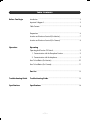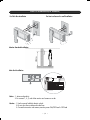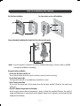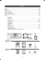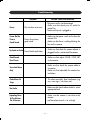
1
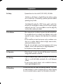
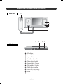
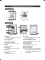
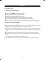
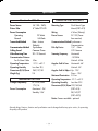
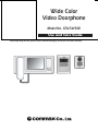
Wide Color
Video Doorphone
Model No. CDV-50/50D
Use and Care Guide
Before operating the unit, please read this manual thoroughly and retain it for future reference.
Introduction
The model number is located on the bottom and record the serial number in the space provided
below. Refer to these numbers whenever you call upon your Commax dealer regarding this product.
Model No.
Serial No.
To prevent fire or shock hazard, do not expose the unit to rain or moisture.
CAUTION
RISK OF ELECTRIC SHOCK
DO NOT OPEN
CAUTION : TO REDUCE THE RISK OF ELECTRIC SHOCK, DO
NOT REMOVE COVER (OR BACK). NO USER-SERVICEABLE
PARTS INSIDE. REFER SERVICING TO QUALIFIED SERVICE
PERSONNEL.
This symbol is intended to alert the
user to the presence of uninsulated
“dangerous voltage” within the
product’s enclosure that may be of
sufficient magnitude to constitute a
risk of electric shock to persons.
This symbol is intended to alert the
user to the presence of important
operating and maintenance
(servicing) instructions in the
literature accompanying the
appliance.
WARNING : TO REDUCE THE RISK OF
FIRE OR SHOCK HAZARD, DO NOT
EXPOSE THIS EQUIPMENT TO RAIN OR
MOISTURE
CAUTION : TO REDUCE THE RISK OF FIRE
OR SHOCK HAZARD AND ANNOYING
INTERFERENCE, USE THE RECOMMEDED
ACCESSORIES ONLY
CAUTION : TO REDUCE THE RISK OF FIRE
OR SHOCK HAZARD, REFER CHANGE OF
SWITCH SETTING INSIDE THE UNIT TO
QUALFIED SERVICE PERSONNEL
CAUTION : TO REDUCE THE RISK OF FIRE
OR SHOCK HAZARD, REFERMOUNTING
OF THE OPTIONAL INTERFACE BOARD
TO QUALIFIED SERVICE PERSONNEL
2001 COMMAX COMPANY LIMITED
All Rights Reserved
Commax are registered and trademarks used by
commax company limited
‐ 2 ‐
Important Safeguards
1. Read Instructions - All safety and operating 10. Damage Requiring Service - Unplug this
instructions should be read before the unit is
equipment from the power source and refer
operated.
servicing to qualified service personnel under
the following conditions:
2. Retain Instruction - The safety and operating
a. when the power supply cord or plug is
instructions should be retained for future
damaged;
reference.
b. if liquid has been spilled or objectes have
fallen into the unit.;
3. Heed Warnings - All warnings on the
c. if the equipment has been exposed to rain
equipment and in the operating instructions
or water;
should be adhered to.
d. if the equipment has been dropped or
otherwise damaged;
4. Follow Instruction - All operating and use
e. when the equipment exhibits a distinct
instructions should be followed.
change in performance - this indicates a
need for service.
5. Ventilation - Slots and openings in the
cabinet are provided for ventilation and to 11. Water and Moisture - Do not use this
protect it from overheating.
product near water, for example, near a
bath tub, wash bowl, kitchen sink, or laundry
6. Power Sources - This equipment should be
tub, in a wet basement, or near a swimming
operated only from the type of power source
pool, and the like.
indicated on the marking label.
12. Accessories - Do not place this product on an
7. Grounding - This product is equipped with a
unstable cart, stand, tripod, bracket, or table.
polarized alternating - current line plug. This
The product may fall, causing serious injury
plug will fit into the power outlet only
to a child or adult, and serious damage to
oneway. This is a safety feature.
the appliance.
Note : Do not place this product directly on
8. Power Cord Protection - Power- supply
wood or simulated woods surfaces as theses
cords should be routed so that they are not
surfaces are easily damaged.
likely to be walked on or pinched by items
placed upon or against them; pay particular
attention to cords at plugs, convenience 13. Object and Liquid Entry - Never push objects
receptacles and the point where cords exit
of any kind into this product through
from the equipment.
openings as they may touch dangerous
voltage points or short-out parts that could
9. Overloading - Do not overload power outlets
result in a fire or electric shock. Never spill
and extension cords as this can result in a
liquid of any kind on the product.
risk of fire or electric shock.
‐ 3 ‐
Important Safeguards
14.Servicing - Do not attempt to service this 20 Lightning - For added protection for this
product before a lightning storm, or when it
product yourself as opening or removing
is left unattached and unused for long
covers may expose you to dangerous voltage
periods of time, unplug it from the wall outlet
or other hazards. Refer all servicing to
and disconnect the antenna or cable system.
qualified service personnel.
This will prevent damage to the product due
to lightning and power-line surges. Be sure
15 Replacement Parts - When replacement
is properly grounded, as defined above. If
parts are require, be sure the service
you live in an area heavily prone to lightning
technician has used replacement parts
stroms, it is recommended that you invest in
specified by the manufacturer or having the
power-line, telephone-line, RF cable and
same characteristics as the original part.
Actuator/Polarization surge protectors to
protect your system from possible damage.
16 Safety Check - Upon completion of service or
repairs to this product, ask the service
technician to perform safety checks to
Note to system installer: This reminder is
determine that the product is in proper
provided to call the system installer’s
operating condition.
attention that provides guidelines for
proper grounding and, in particular,
17 Power Line -The system should not be located
specifies that the cable ground shall be
near overheat power lines or other electric
connected to the grounding system of the
light or power circuits, or where it can fall
building, as close to the point of cable
into power lines or circuits.
entry as practical.
18 Attachment - Do not use attachments not
recommended by the product manufacturer
21 Protective Attachment Plug - The product is
as they may cause hazards.
equipped with an attachment plug having
overload protection. This is safety feature.
19 Outdoor Cable Protection - All outdoor
See Instruction Manual for replacement or
connections should be protected from
resetting of protective device. If replacement
moisture. Internal heating can draw moisture
of the plug is required, be sure the service
or condensation into the covering of the unit
technician has used a replacement plug
and affect its operation.
specified by the manufacturer that has the
same overload protection as the original
plug.
‐ 4 ‐
Table Contents
Before You Begin
Introduction ..............................................................................................2
Important Safeguard ..................................................................................3
Table Contents ...........................................................................................5
Preparations ..............................................................................................6
Location and function of controls (For Monitor) .............................................7
Location and function of controls (For Camera) .............................................8
Operation
Operating
Operating And Function Of Control.............................................................9
1. Communication with the Doorphone Function ......................................9
2. Communication with the Interphone ....................................................9
How To Installation (For Monitor)...............................................................10
How To Installation (For Camera) ..............................................................11
Part List ................................................................................................12
Troubleshooting Guide
Troubleshooting Guide .....................................................................13
Specifications
Specifications ......................................................................................14
‐ 5 ‐
Preparation
On Safety
·Operate the unit on free volt AC(100~240V), 50/60Hz
· Should any solid object or liquid fall into the cabinet, unplug
the unit and have it checked by qualified personnel before
operating it any further.
· One blade of the plug (for 120V Version, only) is wider than
the other for the purpose of safety and will fit into the power
outlet only one way. If you are unable to insert the plug fully
into the outlet, contact your dealer.
On Installation
·Allow adequate air circulation to prevent internal heat build-up.
Do not place the unit on surfaces (rugs, blankets, etc) or near
materials (curtains, drapreris) that may block the ventilation
slots.
·Do not install the unit near heat sources such as radiators or air
ducts or in a place subejct to direct sunlight, excessive dust,
mechanical vibration or shock.
·Keep the unit and glass away from equipment with strong
magnets, such as a microwave oven or large loudspeakers.
·Do not place any heavy object on the unit.
On Operation
·When the unit is not in use, turn off the power to conserve
energy and to extend its useful life.
On Cleaning
·Clean the cabinet away, panel and controls with a dry soft
cloth, or a soft cloth lightly moistened with a mild detergent
solution.
·Do not use any type of solvent, such as alcohol or benzine,
which might damage the finish.
On Repacking
Do not throw away the carton and packing materials. They make
an ideal container in which to transport the unit. When shipping
the unit to another location, repack it as illustrated on the carton.
‐ 6 ‐
Location And Function of Control (For Monitor)
Front View
10
1
2
3
4
11
5
6
Side View
L.E.D Indicator
Monitoring Button
Interphone Button
Release(Open/Close) Button
VOLume Adjust Controller
BRightness Adjust Controller
CONTrast Adjust Controller
COLOR Adjust Controller
POWER OFF/ON(Stand By)
Handset
Speaker
‐ 7 ‐
7 8
9
Location And Function of Control (For Camera)
DRC-4CA
①
②
③
⑨
④
⑩
⑪
⑥
⑤
⑦
⑧
DRC-40CS
Microphone
When Turn on the[CALL] button on the panel, and
conversation with residents.
C.C.D. Camera Lens
Built-in Color 1/4”C.C.D lens
Camera Protection Window
Prevent the scratch from the other matters.
Speaker
Aural from the resident.
Calling Button
Turn on the [CALL] button if desired calling.
Front Panel
No surface on corroision material.
Name Card
Indicated in resident address.
Screw Hole
Use the assembly panel. Note:Before connection,
contact to technical engineer.
Angular Field Of View For Camera
Adjust the angular field of the camera for manually.
Connection Wire Release
Connection Terminal
Use the connection with your residents.
Operation Indication Lamp
Bracket for Wall mount
Note: Do not make any wire connections
these terminals or level the cover off
while the unit is plugged into an DC
power supplier.
‐ 8 ‐
Operation
Communication Functions
1. Communicate with the Video Doorphone
Turn on the [CALL]
button on the camera of the door
Calling sound from the monitor and LED indicator flicker
Pick up the handset, communicate with visitor on the door.
(Monitor screen operating about 90 seconds and then picture is off automatically).
Your visitor with communicated off. Lift down the handset that door LED indicator off.
Turn on the [DOOR]
button your desire any times, pick up the handset communicate with the door.
2. Communicate with the Interphone(Optional)
Pick up the handset, Turn on the [CALL] ⊙ button with extention interphone (DP-4VR). Sound from the
interphone. Now responding from interphone, communicate with your desire.
During busy lines with monitor and interphone, turn on the [CALL] ⊙ button on the door indicator L.E.D.
flicker you can see outside on the door about 90 seconds and communicate with monitor, interphone and
door.
Calling from the door, responding and communicate with the interphone which operating to rectifier.
Busy lines with the monitor and door, pick up the interphone which can communicate with the monitor or
door
You can signal to the monitor when turn on the [CALL] ⊙ button.
Notice When the monitor picture is off, do not operation with door release which expandable interphone.
‐ 9 ‐
How To Installation(For Monitor)
For Flush Box Installation
For Semi-surface on the wall Installation
Monitor Standard Installation
Main Unit Installation
Rectifier
DC 18V
1Amp
CDV-50D
Rectifier
Power
Camera
Interphone
Notice : 1. 4wires and polarity
2. For connect 1, 2, 3, and 4 that monitor and camera as order.
Caution : 1. Use the coaxial cable for electric schcok
2. Do not short lines outside and inside lines
3. Connect that monitor and camera, monitor power ON/OFF level is OFF level
‐ 10 ‐
How To Installation (For Camera)
For Flush Box Installation
Camera
For Semi-surface on the wall Installation
Flush Box
Camera
Screw
Bracket
Fixed Screw
Camera
Screw
Camera
Screw
Camera Standard Installation(For Height/Up/Down/Horizontal Angular)
8
Up
Down
Notice : If you have questions connection the wires for installation following up, Contact to seller or qualified
service personnel before not operating.
Procaution before Installation
Do not Aim The Camera At The Sun
Do not aim the camerr at the sun or point it at the sun even if you are not shooting.
Do not Shoot Intense Light
Framing intense light such as a spotlight may cause bloom or smear.
Never Touch Internal Parts
Do not touch the internal parts of the camera other than that parts specified. Otherwise, the camera may
malfunction.
Check The Ambient Temperature And Humidity
Avoid using the camera where the temperature is hotter or colder than specified. Otherwise, the quality of
images may deteriorate or internal parts may be affected. Special care is required to use the camera at high
temperature and humidity.
‐ 11 ‐
Part List
Monitor..............................................................................................................................................1unit
Hand set ............................................................................................................................................1unit
Bracket for Monitor .............................................................................................................................1unit
Connect Connector(4P)........................................................................................................................2unit
Fixed screw for monitor .......................................................................................................................1unit
Fixed screw for monitor bracket ...........................................................................................................2unit
Manual ..............................................................................................................................................1unit
For DRC-4CA
Camera ................................................................................................................................1unit
Camera Flush Box .................................................................................................................1unit
Camera Screw ......................................................................................................................2unit
Hexagon Lench .....................................................................................................................1unit
For DRC-40CS
Camera ................................................................................................................................1unit
Camera Bracket ....................................................................................................................1unit
Camera Fixed Screw .............................................................................................................1unit
Fixed Screw for Camera ........................................................................................................2unit
Notice:Checking accessories as the below pictures
Connector
(4p-2 EA)
Fixed Screw
Manual
CDV-50
Handset
Bracket
Monitor
Bracket Fixed Screw
Manual
A Type Camera
(DRC-4CA)
Flush Box
Camera Screw
Hexagon Lench
B Type Camera
(DRC-40CS)
Camera
Camera Bracket
‐ 12 ‐
Fixed Screw
Bracket Fixed Screw
Troubleshooting
Symptom
Power
Power But No
Picture
Good Sound
Possible Cause And Corrections
The unit does not turn on.
- The power cord is not disconnected.
- Make sure that check your AC outlet for
power line
- Make sure that unit is plugged in.
Power of no picture,
good sound
- Make sure that power switch on the front the
monitor ON.
- Make sure that there is nothing blocking the
lens on the camera.
No Audio or Video Poor of Audio and Video
- Make sure that check the camera cabinet is
plugged into the monitor and the camera.
Good Sound,
Poor Picture
- Make sure that adjust COLOR, CONT, BRT
on the monitor.
Snow And Noise
- Make sure that check the camera cable to
connection.
- Make sure that adjustable the camera lens
Only
and others.
Dotted Lines Or
Strips
- This often caused by local interference (e.g
cars, neon signs, hair dryers etc).
No Audio
- Make sure that check volume control is set an
appropriate level.
Squealing Noise
At The Monitor
- Make sure that camera is too close to the
monitor
and the volume control is set too high.
On A Camera
‐ 13 ‐
Specifications
Camera for DRC-4CA/40CS
Monitor for CDV-50
Power Source
Picture Tube
Power Consumption
Operating
Normal
Transmitted Method
Communication Method
Calling Sound
Video Receiving Time
Communication Distance
For 0.65mm Cable
Operating Temperature
Operating Humidity
Dimensions(W/H/D)mm
Weight (kg)
AC 100 ~ 240V,
5” Color TFT-LCD
23 Watts
5.5 Watts
Door : 4 wires
(Polarity)
Synchronous
Commax Chime
90±20 Seconds
50m
-10。C~ +40。C
Less than 90%
283/137/50
2.5
Monitor for CDV-50D
Voltage Adaptability
Power Consumption
AC 220V/50Hz
17V/1A
Maximum 1.5W
Stand by 15W
Flush Mount Type
Mount (DRC-4CS)
Wiring
4 Wires (Polarity)
Power Source
DC 13V (Power
from monitor)
Communication Method Synchronous
Communication
Pick-Up Device
1/4” Color
CCD Camera
Scanning Frequency Horizontal
:15.75KHz
Vertical : 60Hz
Angular Field of Lens Horizontal : 68。
Vertical : 55。
Angular Field of Adjust Up : 12.5。
Down : 12.5。
Minimum lllumination 3.0 Lux
Operating Temperature -10。C ~+40。C
Operating Humidity
Less than 90%
Dimensions(W/H/D)mm123/185/45
(DRC-4CA)
98/142/37
(DRC-40CS)
Notice:Camera available - optional
Mounting Type
External design, Features, functions and specifications can be changed without any prior notice., for promoting
the quality of the product.
‐ 14 ‐
Commax User Manual
Jul 2002
CDV-50
Rev.A
513-11, Sangdaewon-dong, Jungwon-ku, Seongnam-city,
Kyungki-do, Korea
Tel.; +82-31-7393-540~550
Fax.; +82-31-745-2133
Web site; www.commax.co.kr
Printed In Korea