1
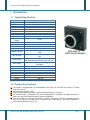
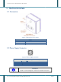
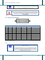
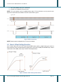
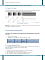
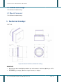
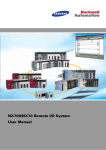
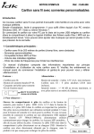
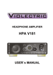
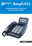
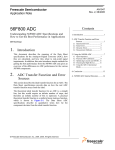
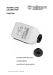
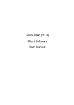
Tri-Linear Series: BMT-2098C-CL
User Manual
Digital Line Scan Cameralink Camera
BalaJi MicroTechnologies Pvt. Ltd.
(A Unit of B.B. Group of Companies)
Corporate Headquarter: New Delhi, India
Sales/business Operation: D-2/20, Sector-10 | DLF Faridabad-121006 |
Haryana, INDIA
Tel # +91-129-4006203 | +91-129-6561300
Email (For Overseas Sales): [email protected]
Email (For India Sales): [email protected]
Website: http://www.balaji-microtechnologies.com/
Tri-Linear Series: BMT-2098C-CL User Manual
Table of Contents
1.
INTRODUCTION
1.1
TYPICAL SPECIFICATION
1.2
PRODUCT KEY FEATURES
1.3
CAMERA CONFIGURABLE FUNCTIONS
1.4
SAFETY MEASURE
1.4.1
Supply voltage Limitation
1.4.2
Power Supply of camera
1.4.3
Warranty
2.
ELECTRICAL & INTERFACE
2.1
2.2
2.3
3.
CONNECTORS
POWER SUPPLY CONNECTOR
CAMERA LINK CONNECTOR
CAMERA FUNCTIONS AND CONTROL
3.1
CAMERA COMMAND & CONTROL
3.2
CAMERA LINK TIMING AND SYNC MODES
3.2.1
Cameralink Timing
3.2.2
Free-run mode without Shutter
3.2.3
Free-run mode with shutter
3.2.4
External Sync modes
3.3
INTEGRATION TIME & LINE RATE
3.4
ELECTRIC SHUTTER
3.5
AREA OF INTEREST (AOI) FUNCTION
3.6
CAMERA RESET FUNCTION
3.7
GAIN & OFFSET SETTING FUNCTION
3.7.1
Offset & Gain Setting (recommended)
3.8
TYPES OF TEST IMAGES
3.8.1
Mode-01 test image
3.8.2
Mode-02 Test Image
4.
SERIAL CAMERA CONFIGURATION
4.1
4.2
4.3
CAMERA COMMAND DETAILS
CAMERA RETURN STRINGS
SPECIAL COMMAND
5
5
5
6
6
6
6
7
8
8
8
9
11
11
13
13
13
14
15
15
16
16
16
17
18
18
18
19
19
19
20
20
5.
MECHANICAL DRAWINGS:
20
6.
ORDERING CODE
21
2015-16 Copyright BalaJi MicroTechnologies Pvt. Ltd.
Page 2
Tri-Linear Series: BMT-2098C-CL User Manual
List of Tables
TABLE 1 : CAMERA SPECIFICATION .........................................................................................................................................5
TABLE 2-LIMITS FOR SUPPLY VOLTAGE....................................................................................................................................6
TABLE 3 CONNECTOR INFORMATION .......................................................................................................................................8
TABLE 4 POWER CONNECTOR ...............................................................................................................................................8
TABLE 5 CAMERALINK CONNECTOR PINS DETAILS .....................................................................................................................9
TABLE 6 CAMERA COMMAND LIST .......................................................................................................................................12
TABLE 7 CAMERA TIMING SPECIFICATION DETAILS ..................................................................................................................13
2015-16 Copyright BalaJi MicroTechnologies Pvt. Ltd.
Page 3
Tri-Linear Series: BMT-2098C-CL User Manual
List of Figures
FIGURE 1 CONNECTORS OF THE CAMERA ------------------------------------------------------------------------------------------------------------ 8
FIGURE 2 POWER SUPPLY CONNECTOR -------------------------------------------------------------------------------------------------------------- 8
FIGURE 3 CAMERALINK CONNECTOR PINS ----------------------------------------------------------------------------------------------------------- 9
FIGURE 4 CAMERA TIMING ------------------------------------------------------------------------------------------------------------------------- 13
FIGURE 5 FREE RUN MODE WITHOUT SHUTTER ---------------------------------------------------------------------------------------------------- 14
FIGURE 6 FREE RUN MODE WITH SHUTTER -------------------------------------------------------------------------------------------------------- 14
FIGURE 7 EXTERNAL SYNC MODE TIMING ---------------------------------------------------------------------------------------------------------- 15
FIGURE 8 AREA OF INTEREST (AOI) FUNCTION ---------------------------------------------------------------------------------------------------- 16
FIGURE 9 CC2 RESET TIMING ----------------------------------------------------------------------------------------------------------------------- 17
FIGURE 10 OFFSET & GAIN SETTING OF THE CAMERA-------------------------------------------------------------------------------------------- 17
FIGURE 11 MODE-01 TEST IMAGE ---------------------------------------------------------------------------------------------------------------- 18
FIGURE 12 MODE-02 TEST IMAGE ---------------------------------------------------------------------------------------------------------------- 19
FIGURE 13 CAMERALINK CAMERA MEHANICAL DRAWING --------------------------------------------------------------------------------------- 20
2015-16 Copyright BalaJi MicroTechnologies Pvt. Ltd.
Page 4
Tri-Linear Series: BMT-2098C-CL User Manual
1. Introduction
1.1 Typical Specification
Name
Resolution
Pixel size
Specification
2098 Tri-Linear CCD (KLI-2113)
14×14 (µm×µm) (8 lines spacing)
MAX. date rate
20 MHz×3
MAX. line rate
≈9.2 KHz
Lens mount
Spectral response
Data Format
Sensor Dynamic
Range
Output Format
Sync/Trigger Input
Sync modes
Integration time
Nikon F-Mount
400nm
700nm Typical
8 bit x 3
Electronic Shutter
Gain & Offset
Offset Range
76 db
Cameralink base ( 1T24 )
CC1
Free-run / External Sync
16 bit through Cameralink Serial Port
10µs MIN. 16bit Setting via Camera Link
Serial
Programmable through Cameralink Serial
Port
1 LSB to 510 LSB 8 bit Resolution
(for 12bit output data format with 2LSB step )
0 V/V to 16 V/V ( MAX. 24dB ) 10 bit
Resolution
Single 12 V (DC), 5%
< 4W
-10 to 50 / 20% to 80%
,
,
Gain Range
Power supply
Power dissipation
Working temp.
Storage temp.
Dimensions
Weight
~
℃ ℃
-40℃ to 75℃ / 10% to 90%
TBD
< 500 GM
Table 1 : Camera Specification
1.2 Product Key Features
The camera is equipped with On Semiconductor, USA Line scan CCD KLI-2113 which is Tri-linear
color CCD sensors.
Area of interest functions (AOI)
Two test image mode which makes more fault finding efficiency in the field.
Our camera design is compatible with several framegrabbers in available in the global market as it
offers very easy serial communication & camera configuration.
The CC1 control line is used by the camera as external sync inputs, CC2 line is optional line which
may use for camera reset (driver part). For external sync mode settings, The camera integration is
synchronized with external sync line.
2015-16 Copyright BalaJi MicroTechnologies Pvt. Ltd.
Page 5
Tri-Linear Series: BMT-2098C-CL User Manual
1.3 Camera configurable functions
AOI function
Camera reset via CC2 line with changeable polar setting
Camera Link DVAL, FVAL, LVAL output format
16bit Integration time setting
Gain & Offset Control
16bit Electric Shutter Control
Sync Modes
16bit Integration time setting
1.4 Safety Measure
1.4.1 Supply voltage Limitation
MIN.
9 V DC
TYP.
12V DC
Table 2-Limits for Supply Voltage
MAX.
17 V DC
1.4.2 Power Supply of camera
•
Warning!
Check camera supply voltage before using the camera.
Cut-off camera’s power supply before plug or un-plug and connectors.
Do not reverse the polarity of the input power! Reversing the polarity of the input
power can severely damage the camera and leave it non-operational.
Information!
Without sufficient cooling, the camera can get hot enough during operation. Allow
sufficient air circulation around the camera to prevent internal heat build-up in your
system and to keep the camera housing temperature during operation below
50°C. Provide additional cooling such as fans or heat sinks if necessary.
2015-16 Copyright BalaJi MicroTechnologies Pvt. Ltd.
Page 6
Tri-Linear Series: BMT-2098C-CL User Manual
1.4.3 Warranty
Camera comes with 12 months warranty from the date of Invoice subject to following below terms.
Do not remove any of the camera’s labels. If labels are removed, user accepts that the warranty of
the camera is void.
Read this Manual first before using the camera
Keep foreign matter outside of the camera
Do not open the housing. Touching internal components may damage them. Be careful not to allow
liquids, flammable, or metallic material inside the camera housing. If operated with any foreign matter
inside, the camera may fail or cause a fire.
Electromagnetic fields: Do not operate the camera in the vicinity of strong electromagnetic fields.
Avoid electrostatic charging.
Transporting: Only transport the camera in its original packaging. Do not discard the packaging.
Cleaning: Avoid cleaning the surface of the CCD sensor if possible. If you must clean it, use a soft,
lint free cloth dampened with a small quantity of high quality window cleaner. Do not use ethylated
alcohol. Because electrostatic discharge can damage the CCD sensor, you must use a cloth that will
not generate electrostatic charge during cleaning (cotton is a good choice).
To clean the surface of the camera housing, use a soft, dry cloth. To remove severe stains, use a soft
cloth dampened with a small quantity of neutral detergent, then wipe dry. Do not use volatile solvents
such as benzene and thinners; they can damage the surface finish of the camera.
2015-16 Copyright BalaJi MicroTechnologies Pvt. Ltd.
Page 7
Tri-Linear Series: BMT-2098C-CL User Manual
2. Electrical & Interface
2.1 Connectors
Figure 1 Connectors of the camera
Notes
1
2
3
LED Status
CameraLink Connector
Power Connector
Table 3 connector information
2.2 Power Supply Connector
Figure 2 Power supply connector
Male Connector (YC8
(YC8-4T) (HR10A Compatible)
No.
Signal
Function
1,2
3,4
VDD
9V—15V DC
GND
GND
Table 4 Power Connector
Information!
GNDs are connected together insid
inside to the Ground of the camera.
c
2015-16
16 Copyright BalaJi MicroTechnologies Pvt. Ltd.
Page 8
Tri-Linear Series: BMT-2098C-CL User Manual
Information!
VDDs are connected together inside the camera.
Warning!
Do not reverse the polarity of the input power to the camera. Reversing
the polarity of the input power can damage the camera and leave it
non-operational
2.3 Camera Link Connector
Figure 3 Cameralink Connector Pins
No.
1
2
3
4
5
6
7
8
9
10
11
12
13
Type: Ribbon Female Connector (3M MDR26 Mini D)
Signal
No.
Signal
Name
Direction
Function
SHIELD
X0X1X2XCLIKX3SerTC+
SerTFGCC1CC2+
CC3CC4+
SHIELD
14
15
16
17
18
19
20
21
22
23
24
25
26
SHIELD
----------------------X0+
X0
OUT
X1+
X1
OUT
X2+
X2
OUT
XCLIK+
XCLIK
OUT
X3+
X3
OUT
SerTCSerTC
IN
SerTFG+
SerTFG
OUT
CC1+
CC1
IN
CC2CC2
IN
CC3+
CC3
IN
CC4CC4
IN
SHIELD
----------------------Table 5 CameraLink Connector Pins details
Cameralink Data 0
Cameralink Data 1
Cameralink Data 2
Cameralink Clock
Cameralink Data 3
Serial To Camera
Serial to Framegrabber
Camera Control 1
Camera Control 2
Camera Control 3
Camera Control 4
2.3.1
Information!
Pins (1, 13, 14, 26 )
The camera mechanical housing is connected with the outer shield of
the cable and is then electrically isolated from the PCB’s inside the
camera. The inner shield of the camera link connector is connected with
the digital ground of camera circuit.
2015-16 Copyright BalaJi MicroTechnologies Pvt. Ltd.
Page 9
Tri-Linear Series: BMT-2098C-CL User Manual
Warning!
User must use high quality CameraLink Cables to ensure good
signal integrity & quality for high speed data transfer.
2015-16 Copyright BalaJi MicroTechnologies Pvt. Ltd.
Page 10
Tri-Linear Series: BMT-2098C-CL User Manual
3. Camera functions and control
3.1 Camera Command & Control
Please refer to Section-4 under Serial Camera Configuration for the detailed protocol of the camera
communication. The camera’s configuration is set through the serial interface which meets the camera
link standard.
Setting
Command
Parameter
Description
Gain Setting for all Channels fomr 0 V/V to 16 V/V The
Default value is 64 (0 db)
Global Gain
G=
0~1023
Red Gain
GR=
0~1023
Red Channel Gain Setting
Green Gain
GG=
0~1023
Green Channel Gain Setting
Blue Gain
O=
Global Offset
Odd Offset
OR=
OG=
(
0~255
Setting
Blue Offset
0~255
0~255
Comman
d
OB=
Parameter
Description
0 255
Blue Channel Offset
Free Run Mode, Default camera integration
time setting
Invalid Setting
Sync Modes (External signal Integration time
Setting)
Default CCD Video Data
Test Image 01
Test Image 02
Default Value is 122, Shutter Value for R,G,B
Channels
Red Channel Shutter Value
Green Channel Shutter Value
Blue Channel Shutter Value
Default Value is 0, Valif for Free Run Modes &
Trig Modes, Integration time setting
LVAL output as line Valid
Sample, L=0
LVAL Output low
LVAL Output High
FVAL output low (Default Value)
FVAL Output High
FVAL Output as line Valid
FVAL Output as line Valid
DVAL output High (Default Value)
~
0
Sync Modes
M=
1
2
Data Source
Shutter Value
Integration Time
S=
0
1
2
U=
0~65535
UR=
UG=0
UB=0
0~65535
0~65535
0~65535
I=
0 65535
LVAL OUTPUT
L=
FVAL OUTPUT
F=
DVAL OUTPUT
D=
)
O = 80 160LSB
Offset Setting for all channels from
0 LSB to 510 LSB ( 2 LSB step), The default value is 80
(160 LSB).
Red Channel Offset
Green Channel Offset
~
0
1
2
3
0
1
2
3
0
2015-16 Copyright BalaJi MicroTechnologies Pvt. Ltd.
Page 11
Tri-Linear Series: BMT-2098C-CL User Manual
Setting
CC2 RESET
CC2 POLAR
AOI FUNCTION
AOI START Position
AOI END Position
Save Configuration
Camera RESET
Save User Set
Restore Configuration
Special Command
Comman
d
Parameter
Description
1
2
3
0
1
0
1
0
1
DVAL Output low
DVAL Output as line Valid
DVAL Output as line Valid
CC2 Camera Reset Disabled (Default)
2E=
CC2 Camera Reset Enable
CC2 Camera Reset Pulse positive (Default)
2P=
CC2 Camera Reset Pulse Negative
AOI Function disabled (Default)
A=
Enable AOI Function
Default Value is 0, Start Position of AOI
B=
0~(n-1)
Window
End position of AOI window, the value must
C=
1~n
larger than AOI start value.
Save current configuration to default working
W=
1
set.
Reset the camera, only core logic of of the
R=
1
camera is reset by this command.
X=
1~3
Save current configuration to user set 1, 2 or 3.
Restore user configuration set, Z=0 will restore
Z=
0~3
Factory configuration set.
0
Display Camera Information
1
Display camera function set
!=
Display camera setting range & other
3
information
4
Display current camera setting lists.
Table 6 Camera Command List
Important:
1. Valid Pixels of the camera (Single Line) = n
2. Electric shutter value setting range is obtained by integration setting value, see instructions below
2015-16 Copyright BalaJi MicroTechnologies Pvt. Ltd.
Page 12
Tri-Linear Series: BMT-2098C-CL User Manual
3.2 Camera Link Timing and Sync Modes
3.2.1 Cameralink Timing
Figure 4 Camera Timing
FVAL is not use for the camera and shall be configure as the frame grabber required, The camera use
TxCLK as the data clock output, LVAL default is the line valid output. This camera doesn’t have electric
shutter function; the LVAL period is equal to integration time while electric shutter function is disabled.
Symbols
tCK
Description
Pixel Clock duration
Minimum
---
Typical Value
---
Maximum
---
tLD
Timing of LVAL to first Data Valid Rising-Edge
5 ns
1/2 tCK
3/4 tCK
tDV
Timing of Data Valid to Clock Rising-Edge
---
1/2 tCK
---
tTRIG
CC1 pulse width for Trig Mode
300 ns
---
---
--1.6 µs
--1.3 µs
---------
tSYNC
tIDLY
t2W
t2DLY
CC1 pulse width for Sync Mode
300 ns
--Timing of CC1 Rising-Edge to Integration Start
CC2 Reset Pulse Width
25 ns
--Timing of Deactivating CC2 to Integration Start
Table 7 Camera Timing Specification Details
3.2.2 Free-run mode without Shutter
The integration & read out are control by the camera & start automatically & immediately after previous
period. Integration time is set by serial command from 0 to 65535 ( 16bit ). The maximum line rate shall
be set by “I=0” command.
2015-16 Copyright BalaJi MicroTechnologies Pvt. Ltd.
Page 13
Tri-Linear Series: BMT-2098C-CL User Manual
Figure 5 Free run mode without shutter
3.2.3 Free-run mode with shutter
The integration & read out are control by the camera & start automatically & immediately after previous
period. Exposure time is set by the electric shutter (“U=XXXXX” command). The maximum shutter time is
limited by current integration time setting.
Figure 6 Free run mode with shutter
Information!
Increasing integration time will lower the line rate of the camera.
operator can use “!=2” special command to obtain integration step,
current integration time and current line rate.
Information!
The line rate will not be changed with change in electric shutter value.
The electric shutter value or exposure time of the camera will not be
changed with change in integration time
2015-16 Copyright BalaJi MicroTechnologies Pvt. Ltd.
Page 14
Tri-Linear Series: BMT-2098C-CL User Manual
3.2.4 External Sync modes
Electric shutter will be automatically disabled by the camera when setting to external sync mode.
Integration time is controlled by external sync pulse period from CC1 input.
Figure 7 External sync mode timing
3.3 Integration time & line rate
Camera default integration settng value is 0,
2015-16 Copyright BalaJi MicroTechnologies Pvt. Ltd.
Page 15
Tri-Linear Series: BMT-2098C-CL User Manual
3.4 Electric Shutter
Calculation for shutter value when shutter function enabled is:
For KLI-2113 CCD based RGB cameras with electric shutter function support, using “UR=XXXXX”,
“UG=XXXXX” and “UB=XXXXX” commands to setting each color channel’s shutter values. Default setting
for each channel is 122.
3.5 Area of Interest (AOI) function
The LVAL signal will change according to AOI setting, when camera’s AOI function is enabled.
Figure 8 Area of Interest (AOI) function
when Area of Interest (AOI) function is disabled, the LVAL output will cover all 2098 pixels output, when
Area of Interest (AOI) is enabled and start point set to “B=2” and end point set to “C=2094”, the LVAL
output will be changed to cover from pixel 3 to pixel 2094 (2092 output data).
Information!
There are few frame grabbers which need to change settings when Area
of Interest (AOI) is enabled.
Area of Interest (AOI) setting can’t increase line rate of the camera.
3.6 Camera reset function
There are two types of camera reset shall be performed
2015-16 Copyright BalaJi MicroTechnologies Pvt. Ltd.
Page 16
Tri-Linear Series: BMT-2098C-CL User Manual
1. one is the software reset (“R=1” command),
2. the other is the optional CC2 pulse reset.
NOTE: CC2 reset function must be enabled before usingit. CC2 reset function can only reset the core
logic of the camera while the software reset will reset the whole system.
Figure 9 CC2 reset timing
NOTE: Default camera configuration for CC2 reset is disabled.
3.7 Gain & Offset Setting Function
Our Tri-linear Series KLI-2113 CCD sensor based RGB cameras offers a digital 10 bit gain and 8 bit
offset setting via serial line. Maximum gain setting value is up to 16V/V (24dB) with 0.015dB steps, default
value G=64 (1V/V or 0dB); offset step is 2LSB in 12bit output format.
Figure 10 Offset & Gain Setting of the Camera
2015-16 Copyright BalaJi MicroTechnologies Pvt. Ltd.
Page 17
Tri-Linear Series: BMT-2098C-CL User Manual
Information!
Increase the gain will also increase the noise of the camera output, but
the total noise to signal (dB) ratio will not change apparently.
Information!
For Tri-linear KLI-2113 CCD sensor based cameras, the gain and offset
of each channel (R, G, B) need to be fine adjusted in field application to
obtain ideal white balance and black balance..
3.7.1 Offset & Gain Setting (recommended)
Offset & Gain Setting (Recommendation)
1. Set all channel to 1X (0dB) gain and maximum offset, serial command “G=64” and “O=255”.
2. Put the camera into total dark environments (for example: mount the lens cap is OK), set each
channel’s offset value to let the output video data just arrived to zero.
3. Put the camera to acquire a total white object images, set each channel’s gain value, make the video
output arrived to maximum (255 if output format is 8 bit, 4095 if 12bit).
4. Repeat steps 3), 4).
5. Save settings (“W=1” or “X=n” command).
IMPORTANT INSTRUCTIONS
1. Any time, user can use “Z=0” command to restore factory settings.
2. Avoid too much incident light to the CCD sensor while adjusting due to the limited anti-blooming
feature of the CCD sensor.
3. Too much incident light to the CCD sensor will saturate the dark reference of the sensor and make
video data drop to nearly zero.
3.8 Types of test images
There are two types of test image is available for testing purpose. The test image is generated inside the
FPGA and jump over the AD conversion.
3.8.1 Mode-01 test image
Figure 11 Mode-01 test image
2015-16 Copyright BalaJi MicroTechnologies Pvt. Ltd.
Page 18
Tri-Linear Series: BMT-2098C-CL User Manual
The above test image is a repeated gray scale gradients cycle every 256 pixels.
3.8.2 Mode-02 Test Image
It’s is divided into two parts: first half valid pixels image is same as mode 1 of the test image; second half
valid pixels is vertical repeated gradients cycle every 256 lines.Please see below:
Figure 12 Mode-02 Test Image
IMPORTANT: Test image are based on total valid pixels of the camera. The Area of Interest (AOI)
function will not change the test image values.
4. Serial Camera Configuration
The camera link interface provides two LVDS signal pairs to communication between the camera and the
frame grabber, it’s an asynchronous serial communication base on RS-232 protocol. The serial line’s
configuration is:
1. Duplex without handshaking
2. 9600 bps 8 bit 1 bit (9600 bauds, 8bit data, no parity bit, 1 stop bit)
, ,
Signal
SerTFG
Direction
OUT
Format
RS644
SerTC
IN
RS644
Description
Serial to Framegrabber
Serial to Camerr
4.1 Camera command details
Our Tri-linear Series KLI-2113 CCD sensor based RGB cameras are based on ASCII protocal of the
serial communication, the command syntex is illustrated as follows:
Command=Parameter
1. Command: one or more characters continued with a “=” character, see section 3.1
2. Parameter: must be one or more characters within “0” to “9”.
3. (CR) Represent the “Enter” character (Hex value is 0x0D), same for below.
4. “Blanc (or SPACE)” character are not allowed in the command syntax.
:
2015-16 Copyright BalaJi MicroTechnologies Pvt. Ltd.
Page 19
Tri-Linear Series: BMT-2098C-CL User Manual
4.2 Camera return strings
<This Section to be added shortly>
4.3 Special Command
<This Section to be added shortly>
5. Mechanical drawings:
UNIT = MM
Figure 13 CameraLink Camera mehanical drawing
IMPORTANT:
1. Mount the lens after removing the protection caps of the camera to avoid dust gathering on CCD’s
optic window.
2. The camera’s typical weight (witho
(without lens adapter and lens) is <450 gm.
2015-16
16 Copyright BalaJi MicroTechnologies Pvt. Ltd.
Page 20
Tri-Linear Series: BMT-2098C-CL User Manual
6. Ordering code
Model Number
BMT-2098C-CL
BMT-2098M-CL
Description
2098 Pixel CCD Cameralink Colour Line Scan
Camera
2098 Pixel CCD Monochrome Cameralink Line Scan
Camera
For more product information or inquiry, please contact
BalaJi MicroTechnologies Pvt. Ltd.
(A Unit of B.B. Group of Companies)
Corporate Headquarter: New Delhi, India
Sales/business Operation: D-2/20, Sector-10 | DLF Faridabad-121006 |
Haryana, INDIA
Tel # +91-129-4006203 | +91-129-6561300
Email (For Overseas Sales): [email protected]
Email(For India Sales): [email protected]
Website: http://www.balaji-microtechnologies.com/
2015-16 Copyright BalaJi MicroTechnologies Pvt. Ltd.
Page 21