1
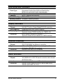
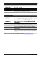
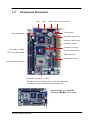
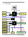
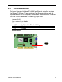
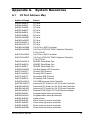
Table of Contents
Chapter 1. Introduction ...................................................................... 3
1.1
1.2
1.3
1.4
Product Overview ........................................................................ 3
Specification ................................................................................ 4
Component Placement ................................................................ 7
Block Diagram ............................................................................. 8
Chapter 2. Hardware Setup ................................................................ 9
2.1
2.2
2.3
2.4
2.5
2.6
2.7
2.8
2.9
2.10
2.11
Jumpers and Connectors Location.............................................. 9
CPU Setting............................................................................... 12
CMOS Setting ........................................................................... 12
Watchdog Timer Setting ............................................................ 13
Embedded Flash Disk ............................................................... 14
Power and Fan Connectors....................................................... 15
Display Interface........................................................................ 16
Ethernet Interface...................................................................... 17
Audio Interface .......................................................................... 18
Serial Port COM2 Mode Configuration ...................................... 19
Switches and Indicators ............................................................ 20
Chapter 3. BIOS Setup...................................................................... 21
Chapter 4. Driver Installation ........................................................... 23
4.1
4.2
4.3
4.4
4.5
4.6
4.7
Install Board’s Software............................................................. 23
Install Ultra ATA IDE Driver ........................................................ 23
Install VGA Driver ...................................................................... 23
Install LAN Driver ...................................................................... 23
Install Audio Driver .................................................................... 23
Link to < Website > Homepage ................................................. 23
Browse this CD.......................................................................... 23
HE-860 User’s Manual
1
Appendix A. System Resources ......................................................25
A.1
A.2
A.3
Appendix B.
B.1
B.2
I/O Port Address Map................................................................ 25
Memory Address Map ............................................................... 27
System IRQ and DMA Resource............................................... 28
Flash the BIOS ...........................................................29
BIOS Auto Flash Tool ................................................................ 29
Flash Method ............................................................................ 29
Appendix C. I/O Port Pin Assignment.............................................31
C.1
C.2
C.3
C.4
C.5
C.6
C.7
C.8
C.9
C.10
2
IDE Port .................................................................................... 31
Floppy Port................................................................................ 32
Parallel Port .............................................................................. 33
RS-232 Serial Port .................................................................... 34
USB Port ................................................................................... 35
IrDA Port ................................................................................... 35
VGA Port ................................................................................... 36
LAN Port ................................................................................... 36
AT Keyboard Port...................................................................... 37
PS/2 Keyboard and Mouse Port................................................ 37
HE-860 User’s Manual
Chapter 1.
1.1
Introduction
Product Overview
COMMELL's HE-860 / HE-860S SBC (Single Board Computer) is an
all-in-one industrial half-size PISA (PCI/ISA)-bus / ISA-bus CPU card based
on VIA Eden embedded low power platform. Based on PISA-bus interface,
HE-860 offers the flexible expansibility with PCI or ISA expansive interfaces
via the industrial backplane. With 1 GBytes per seconds of data transfer rate
let HE-860 provide several times of bandwidth rather than NS Geode,
Transmeta Crusoe, and Intel ULP Celeron based SBC. With VIA Eden
platform, 512 MB PC-133 SDRAM, integrated 3D SVGA8MB VRAM, 10/100
Mbps LAN, UltraATA/100 IDE, AC97 3D Audio, SSD interfaces and ISA
64mA high drive capacity, the HE-860 provides the ideal embedded solutions
for:
Advanced Embedded Computing Platform: advanced 686 level VIA Eden
platform with 533 MHz of speed at 133 MHz of FSB, provides 1 GBytes/sec of
data transfer rate. Based on x86 architecture and VIA's latest technology,
HE-860 supports most of the x86-based OS and AP. That is, with HE-860, the
embedded systems can be integrated and upgraded easily with the existent
and popular x86-based software.
Ultra-Low Power / Fan Free Solution: based on the latest .13 of IC
manufacturing procedure, the operating voltage range of VIA Eden ESP
processor is from only 1.05 to 1.2 volts. The advanced thermal design makes
HE-860 ideal for fan free embedded system designs as well as small size and
lower profile form factors.
All-in-one Integrated Solution: HE-860 integrated with 3D SVGA, 10/100
Mbps LAN, AC97 3D Audio, UltraATA/100 IDE, DiskOnChip embedded solid
state flash disk interfaces and ISA 64mA high drive capacity, provides the
high integration solution for high-end embedded applications features high
speed, high integration, low power, fan free, and full embedded systems with
embedded OS in flash disk.
HE-860 User’s Manual
3
1.2
Specification
General Specification
Form Factor
CPU
Chipset
Memory
BIOS
Green Function
Watchdog Timer
Real Time Clock
Enhanced IDE
ISA High Drive
HE-860 : PISA 1.7 compliant, with 4 bus master PCI
HE-860S : ISA bus interface only
Onboard VIA Eden 533 MHz CPU at 133 MHz FSB
Optional Compatible CPU Configuration for OEM
VIA Eden 400, 667 MHz CPU (fan free operating)
VIA EBGA C3 800, 977 MHz and above CPU (with
onboard low profile CPU cooling fan)
VIA PLE133T chipset with 8601T and 686B
512 MB PC100/133 SDRAM on 1 168-pin DIMM socket
Phoenix-Award 2Mb PnP flash BIOS
ACPI version 1.0 and APM version 1.2 compliant
6-level generates NMI or system reset watchdog timer
VIA 686B built-in RTC with onboard lithium battery
PCI enhanced IDE interface supports dual ports up to 4
ATAPI devices with UltraATA/100 supported
IDE2 Vcc power supported for cable free DOM
(DiskOnModule)
ISA 64mA high drive capacity with TI 245 buffer, supports
over 20 pieces of ISA-based add-on cards
Multi-I/O Port
Chipset
Serial Port
USB Port
Parallel Port
Floppy
IrDA Port
K/B & Mouse
4
VIA 686B chipset built-in super I/O controller
1 x RS-232 serial port COM1
1 x jumper selectable RS-232/422/485 serial port COM2
Both with 16C550 compatible UART and 16 bytes FIFO
Two USB ports with USB version 1.1 compliant
One bi-direction parallel port with SPP/ECP/EPP mode
One floppy port supports up to two FDD
One IrDA compliant Infrared interface supports SIR
External PS/2 keyboard / mouse port with MiniDIN on
bracket; Internal AT keyboard port
HE-860 User’s Manual
Solid State Disk Interface
Flash Type
M-systems DiskOnChip-2000 and DiskOnChip
Millennium embedded solid state flash disk
Package
Single chip flash disk in 32-pin DIP JEDEC
Capacity
Up to 1 GBytes flash memory
Data Reliability
ECC / EDC data protection
Memory Window 8 Kbytes of memory window
Display Interface
Chipset
Video Memory
Display Type
Connector
VIA 8601T built-in Trident Blade3D SVGA controller
8 MBytes shared with system memory
CRT, LCD monitor and analog VGA display
Optional onboard TMDS interface for TMDS LCD
DB15 female connector on bracket
Optional onboard 20-pin header for TMDS interface
Ethernet Interface
Chipset
Type
Connector
PCI RTL8100(B) Fast Ethernet controller
10Base-T / 100Base-TX, auto-switching Fast Ethernet,
full duplex, IEEE802.3U compliant
External RJ45 with LED on bracket
Audio Interface
Chipset
Interface
Connector
HE-860 User’s Manual
VIA 686B built-in AC97 3D audio controller with onboard
ALC201A codec
Line-in, line-out, Mic-in and CD-in interface
Internal 10-pin header for line-in, line-out and mic-in
Internal 4-pin wafer for CD-in
5
Power and Environment
Power Req.
Dimension
Weight
Temperature
+5V, +12V, -12V DC
185 x 127 mm (L x H)
0.28 Kg
Operating within 0 ~ 60oC (32 ~ 140oF)
Storage within -20 ~ 85oC (-4 ~ 185oF)
Ordering Code
HE-860VL
HE-860VXL
HE-860SVL
HE-860SVXL
OEM Version
Half-size PISA-bus Embedded VIA Eden CPU Card with
onboard VIA Eden 533MHz CPU, VGA, LAN, Audio,
DiskOnChip Interfaces and ISA High Drive Capacity
Same as HE-860VL but with onboard TMDS Panel
Link Interface
Half-size ISA-bus Embedded VIA Eden CPU Card with
onboard VIA Eden 533MHz CPU, VGA, LAN, Audio,
DiskOnChip Interfaces and ISA High Drive Capacity
Same as HE-860SVL but with onboard TMDS Panel
Link Interface
Other Configuration Based on HE-860 with Compatible
Eden/C3 CPU, Optional Onboard Functions and Others
for OEM Projects
Online product information detail and updates are available on http://www.commell.com.tw
6
HE-860 User’s Manual
1.3
Component Placement
VGA
LAN
COM1 PS/2 K/B and Mouse
AT Keyboard
RS-232/422/485
ISA 64mA High Drive
RTL8100 LAN Chipset
VIA686B Chipset
VIA 8601T Chipset
One 168-pin DIMM
Phoenix-Award BIOS
up to 512 MB SDRAM
TMDS Interface
DiskOnChip Socket
Dual UltraATA/100 IDE
Embedded VIA Eden / C3 CPU
VIA Eden Ultra Low Voltage CPU for Fan Free Operation
VIA EBGA C3 CPU with Onboard CPU Cooling Fan
Same Location on HE-860S
(Half-size ISA Bus CPU Card)
HE-860 User’s Manual
7
1.4
Block Diagram
FSB 100/133 MHz
CRT/LCD
VIA
Monitor
Flat Panel
(TMDS)
8601T
N/B
TMDS
PC133
1 x 168-pin DIMM
512 MB PC133 SDRAM
PCI Bus Interface
10/100 Mbps
LAN
RTL
8100B
HE-860VL
ATAPI Device
Audio Devices
HE-860VXL
ATA100 IDE
Codec
VIA
686B
S/B
PISA Backplane
USB Devices
64mA ISA
PS/2 Keyboard
PS/2 Mouse
ISA Bus Interface
HE-860SVL
Floppy
64mA ISA
HE-860SVXL
Serial Device
Parallel Device
8
DiskOnChip
ISA Backplane
HE-860 User’s Manual
Chapter 2.
Hardware Setup
This chapter contains the information for installation of hardware. The install
procedure includes jumper settings, CPU and memory installation, fan, I/O
and panel connections.
2.1
Jumpers and Connectors Location
LAN_CON1
VGA
COM1
PS2
PWRCON1
ATXCON
USB
CDIN
JCSEL2 (J2)
JCSEL1 (JCSEL)
JAUDIO
JCOM2
FDD
PRINTER
JAT_KB
JLAN
JRTC
SIR
JPVOD1 (VXL Only)
JTMDS
SWDT
IDE2
JDOC
IDE1
JWDT
DIMM1
JDOM
DOC (U5)
CPUFAN
JFRNT
Same Location on HE-860S
(Half-size ISA Bus CPU Card)
HE-860 User’s Manual
9
2.1.1
Jumper Reference
Jumper
JRTC
JWDT
SWDT
JDOC
JDOM
JPVOD1
JLAN
JCSEL1 (JCSEL)
JCSEL2 (J2)
10
Function
COMS Setting
Watchdog Timer Setting
Watchdog Timer Timeout Value Setting
DiskOnChip Address Setting
DiskOnModule Power Setting
TMDS Voltage Setting
LAN Enable / Disable Setting
COM2 RS232/422/485 Mode Setting
COM2 RS232/422/485 Mode Setting
Section
2.3
2.4
2.4
2.5.1
2.5.2
2.7
2.8
2.10
2.10
HE-860 User’s Manual
2.1.2
Connector Reference
Connector
DIMM1
IDE1
IDE2
FDD
PRINTER
USB
JCOM2
DOC (U5)
JAT_KB
SIR
PWRCON1
ATXCON
JFRNT
CPUFAN
JAUDIO
CDIN
JTMDS
VGA
PS2
LAN_CON
COM1
HE-860 User’s Manual
Function
168-pin DIMM Socket
40-pin Primary IDE Port
40-pin Secondary IDE Port
34-pin FDD Port
26-pin Parallel Port
10-pin 1st / 2nd USB Port
10-pin COM2 RS232/422/485 Serial Port
32-pin DiskOnChip Socket
5-pin AT/PC Keyboard Connector
5-pin SIR Infrared Port
6-pin AT P8 Power Connector
3-pin ATX Signal Connector
10-pin Front Panel Connector
3-pin CPU Fan Connector
10-pin Audio Connector
5-pin CD-in Connector
20-pin TMDS Panel Link Connector
DB15 Female VGA Port on Bracket
6-pin MiniDIN PS/2 Keyboard and Mouse
Connector on Bracket
RJ45 Primary LAN Port on Bracket
DB9 Male COM1 Port on Bracket
Remark
Standard
Standard
Standard
Standard
Standard
Standard
Standard
Standard
Standard
Standard
Standard
Standard
Standard
Standard
Standard
Standard
VXL only
Standard
Standard
VL, VXL only
Standard
11
2.2
CPU Setting
The board is based on VIA embedded Eden platform features standard
x86 architecture, high performance, low power consumption and supports
VIA Eden / C3 CPU with onboard SMT.
With VIA’s high integrated PLE133T chipset and Eden embedded CPU,
the board can easily update the old 486 or 586 level embedded x86 based
systems like Intel mobile Pentium, Tillamook, and other RISC based
systems like NS GX1 and Transmeta Crusoe. Based on the latest 0.13
micron of semi-conductor technology, the VIA Eden works at the ultra low
voltage of 1.0 to 1.2 Volts of Vcore. It makes the VIA Eden platform be the
ideal solution for embedded high performance applications.
The FSB, ratio and voltage of CPU is default set by onboard CPU and
without any additional jumper selection.
2.3
CMOS Setting
The board’s data of CMOS can be setting in BIOS. If the board refuses to
boot due to inappropriate CMOS settings, here is how to proceed to clear
(reset) the CMOS to its default values.
Jumper: JRTC
Type: onboard 3-pin header
JRTC
1-2
2-3
Mode
Clear CMOS
Normal Operation
Default setting
JRTC
1
3
12
HE-860 User’s Manual
2.4
Watchdog Timer Setting
The onboard watchdog timer can be used on system-self monitor and reset.
2.4.1
Watchdog Timer Mode Setting
Jumper: JWDT
Type: onboard 3-pin header
JWDT
1-2
2-3
Watchdog Timer
Active NMI
Reset
Default setting
SWDT
1
ON DIP
1 2 3 4
1
2
3
4
3
JWDT
2.4.2
Watchdog Timer Time-out Value Setting
Jumper: SWDT
Type: onboard 4-way DIP Switch
Time-out Value
1 Sec.
2 Sec.
10 Sec.
20 Sec.
110 Sec.
220 Sec.
Default setting
HE-860 User’s Manual
SWDT
OFF
OFF
OFF
OFF
ON
ON
OFF
OFF
ON
ON
OFF
OFF
ON
ON
OFF
OFF
OFF
OFF
OFF
ON
OFF
ON
OFF
ON
13
2.5
Embedded Flash Disk
The board supports both 32-pin DiskOnChip 2000 and DiskOnChip IDE Pro
embedded flash disk. The onboard 32-pin socket, supports DiskOnChip 2000
single chip flash disk in 32-pin DIP JEDEC with jumper selectable address on
jumper JDOC; onboard 40-pin IDE2 box header supports normal DOM
(DiskOnModule) or M-systems DiskOnChip IDE Pro flash disk with jumper
selectable +5V Vcc power for cable free applications on jumper JDOM.
2.5.1
DiskOnChip 2000 Address Setting
Jumper: JDOC
Type: onboard 4-pin header
JDOC
DiskOnChip Address
1-2
2-3
D000h
D800h
Default setting
JDOM
1
2
JDOC
1
2.5.2
3
DiskOnModule or DiskOnChip 2000 IDE Pro
Jumper: JDOM
Type: onboard 2-pin header
JDOM
OFF
ON
Default setting
14
+5V on Pin-20 of IDE2
Disable
Enable
HE-860 User’s Manual
2.6
Power and Fan Connectors
ATXCON
1
2
3
6
1
PWRCON1
CPUFAN
1
2
3
Connector: PWRCON1
Type: 6-pin Standard AT P8 Power Connector
Pin
1
2
3
4
5
6
Description
Power Good
Vcc
+12V
-12V
Ground
Ground
Connector: ATXCON
Type: 3-pin Header for ATX Function
Pin
1
Description
5V Standby
Pin
2
Description
Ground
Pin
3
Description
Power On
Pin
3
Description
Ground
Connector: CPUFAN
Type: 3-pin Header for CPU or System Fan
Pin
1
Description
Fan Ctrl
HE-860 User’s Manual
Pin
2
Description
+12V
15
2.7
Display Interface
The board uses VIA8601T integrated Trident 2xAGP VGA accelerator with
3D/2D engine and up to 8 MB of video memory shared with system memory.
It supports CRT and LCD monitor via the standard DB15 female connector on
bracket an optional TMDS panel link interface via onboard 20-pin header
JTMDS and voltage jumper JPVOD1.
JPVOD1
1 2 3
2
20
1
19
JTMDS
Jumper: JPVOD1
Type: onboard 3-pin header
JPVOD1
1-2
2-3
TMDS Panel Voltage Setting
+5V
+3.3V
Default setting
Connector: JTMDS
Type: 20-pin header
Pin
1
3
5
7
9
11
13
15
17
19
16
Description
TX1+
SHLD1
TXC+
Ground
N/C
TX2+
SHLD2
TX0+
N/C
DDC_Data
Pin
2
4
6
8
10
12
14
16
18
20
Description
TX1SHLDC
TXC+5V
N/C
TX1+
SHLD0
TX0N/C
DDC_Clock
HE-860 User’s Manual
2.8
Ethernet Interface
The board integrated with dual RTL8100 Fast Ethernet controller, provides
the 10Base-T/100Base-TX auto-switching Fast Ethernet interface with full
duplex and IEEE 802.3U compliant, connects with RJ45 connector on bracket.
The LAN function can enable or disable by jumper JLAN.
Jumper: JLAN
Type: onboard 3-pin header
JLAN
LAN Enable / Disable Setting
1-2
2-3
Enable
Disable
Default setting
1
3
JLAN
HE-860 User’s Manual
17
2.9
Audio Interface
The board integrates with AC97 3D audio interface with VIA686B built-in
audio controller and ALC201A codec, provides line-in, line-out, Mic-in, and
CD-in interfaces.
JAUDIO
2
10
1
9
CDIN
1
2
3
4
Connector: JAUDIO
Type: 10-pin header
Pin
1
3
5
7
9
Description
Line – Right
Line – Left
MIC
N/C
Line Out – Right
Pin
2
4
6
8
10
Description
Ground
MIC
Ground
Line Out – Left
Ground
Connector: CDIN
Type: 4-pin header
Pin
1
2
3
4
18
Description
CD – Left
Ground
Ground
CD – Right
HE-860 User’s Manual
2.10
Serial Port COM2 Mode Configuration
The board offers two serial ports including one RS232 COM1 and one jumper
selectable RS232/422/485 COM2. The configuration of COM2 can be setting
with jumpers JCSEL1 (JCSEL) and JCSEL2 (J2).
JCOM2
2
10
1
9
1 2
JCSEL2
5 6
Jumper: JCSEL1 (JCSEL), JCSEL2 (J2)
Type: onboard 6-, 12-pin header
COM2 Mode
RS-232
RS-422
RS-485
Default setting
1
JCSEL1
10
2
3
11
12
JCSEL2 (J2)
JCSEL1 (JCSEL)
1-2
5-6
3-4
1-2/4-5/7-8/10-11
2-3/5-6/8-9/11-12
2-3/5-6/8-9/11-12
Connector: JCOM2
Type: 10-pin header
Pin RS232
1
DCD
3
TXD
5 Ground
7
RTS
9
RI
RS422
TXRX+
N/C
N/C
N/C
HE-860 User’s Manual
RS485
485N/C
N/C
N/C
N/C
Pin
2
4
6
8
10
RS232
RXD
DTR
DSR
CTS
N/C
RS422
TX+
RXN/C
N/C
N/C
RS485
485+
N/C
N/C
N/C
N/C
19
2.11
Switches and Indicators
JFRNT
1
2
9
10
1
2
13
14
Connector: JFRNT (Type-I)
Type: onboard 10-pin header
Pin
1
3
5
7
9
Description
Pin
Description
Function
Ground
Active
Reset
PWR BN
Speaker
2
4
6
8
10
Vcc
Vcc
Ground
Ground
Vcc
Power LED
HDD LED
Reset
Power Button
Speaker
10-pin JFRNT includes additional speaker and power LED cables in the packing list.
Connector: JFRNT (Type-II)
Type: onboard 14-pin header
Function
Signal
PIN
Signal
Vcc (+)
1
2
(+) Vcc
Active
3
4
N/C
Reset
5
6
GND
GND
7
8
Vcc
N/C
9
10
N/C
Power
PWRBT
11
12
N/C
Button
GND
13
14
SPKIN
IDE LED
Function
Power
LED
Reset
Speaker
20
HE-860 User’s Manual
Chapter 3.
BIOS Setup
The single board computer uses the Award BIOS for the system configuration.
The Award BIOS in the single board computer is a customized version of the
industrial standard BIOS for IBM PC AT-compatible computers. It supports
Intel x86 and compatible CPU architecture based processors and computers.
The BIOS provides critical low-level support for the system central processing,
memory and I/O sub-systems.
The BIOS setup program of the single board computer let the customers
modify the basic configuration setting. The settings are stored in a dedicated
battery-backed memory, NVRAM, retains the information when the power is
turned off. If the battery runs out of the power, then the settings of BIOS will
come back to the default setting.
The BIOS section of the manual is subject to change without notice and is
provided here for reference purpose only. The settings and configurations of
the BIOS are current at the time of print, and therefore they may not be
exactly the same as that displayed on your screen.
To activate CMOS Setup program, press <DEL> key immediately after you
turn on the system. The following message “Press DEL to enter SETUP”
should appear in the lower left hand corner of your screen. When you enter
the CMOS Setup Utility, the Main Menu will be displayed as Figure 3-1. You
can use arrow keys to select your function, press <Enter> key to accept
the selection and enter the sub-menu.
Figure 3-1. CMOS Setup Utility Main Screen
Phoenix – Award BIOS CMOS Setup Utility
>Standard CMOS Features
>Frequency/Voltage Control
>Advanced BIOS Features
Load Fail-Safe Defaults
>Advanced Chipset Features
Load Optimized Defaults
>Integrated Peripherals
Set Supervisor Password
>Power Management Setup
Set User Password
>PnP / PCI Configurations
Save & Exit Setup
>PC Health Status
Exit Without Saving
Esc : Quit
↑↓→←
: Select Item
F10 : Save & Exit Setup
HE-860 User’s Manual
21
Notes
22
(This page left blank intentionally)
HE-860 User’s Manual
Chapter 4.
Driver Installation
The driver CD offers auto-run menu. It will detect and select the type of single
board computer and helps you install the drivers automatically.
4.1
Install Board’s Software
The selection helps you install the drivers of chipset. It will detect your version
of OS automatically.
4.2
Install Ultra ATA IDE Driver
The selection helps you to install the driver of IDE interface.
4.3
Install VGA Driver
The selection helps you to install the driver of onboard VGA interface.
4.4
Install LAN Driver
The selection helps you to install the driver of onboard LAN interface.
4.5
Install Audio Driver
The selection helps you to install the driver of onboard audio interface.
4.6
Link to < Website > Homepage
The selection help you to link to the website to find the updated technical
documents and download directly.
4.7
Browse this CD
The selection helps you to find the drivers in this CD directly.
HE-860 User’s Manual
23
Notes
24
(This page left blank intentionally)
HE-860 User’s Manual
Appendix A.
A.1
System Resources
I/O Port Address Map
Address Range
0x0022-0x003F
0x0044-0x0047
0x004C-0x006F
0x0072-0x007F
0x0090-0x0091
0x0093-0x009F
0x00A2-0x00BF
0x00E0-0x00EF
0x0100-0x0CF7
0x0D00-0xFFFF
0x03B0-0x03BB
0x03B0-0x03BB
0x03C0-0x03DF
0x03C0-0x03DF
0x0A79-0x0A79
0x0279-0x0279
0x0274-0x0277
0xD000-0xD00F
0x01F0-0x01F7
0x03F6-0x03F6
0x0170-0x0177
0x0376-0x0376
0xD400-0xD41F
0xDC00-0xDCFF
0xE000-0xE003
0xE400-0xE403
0xE800-0xE8FF
0x0020-0x0021
0x00A0-0x00A1
0x0040-0x0043
0x0000-0x000F
0x0081-0x0083
0x0087-0x0087
0x0089-0x008B
HE-860 User’s Manual
Device
PCI bus
PCI bus
PCI bus
PCI bus
PCI bus
PCI bus
PCI bus
PCI bus
PCI bus
PCI bus
VIA CPU to AGP Controller
VIA Tech VT8361/VT8601 Graphics Controller
5.12.01.3105
VIA CPU to AGP Controller
VIA Tech VT8361/VT8601 Graphics Controller
5.12.01.3105
ISAPNP Read Data Port
ISAPNP Read Data Port
ISAPNP Read Data Port
VIA Bus Master IDE Controller
Primary IDE Channel
Primary IDE Channel
Secondary IDE Channel
Secondary IDE Channel
VIA USB Universal Host Controller
Avance AC'97 Audio for VIA (R) Audio Controller
Avance AC'97 Audio for VIA (R) Audio Controller
Avance AC'97 Audio for VIA (R) Audio Controller
Realtek RTL8139(A) PCI Fast Ethernet Adapter
Programmable interrupt controller
Programmable interrupt controller
System timer
Direct memory access controller
Direct memory access controller
Direct memory access controller
Direct memory access controller
25
0x008F-0x0091
0x00C0-0x00DF
0x0060-0x0060
0x0064-0x0064
0x0378-0x037F
0x03F8-0x03FF
0x02F8-0x02FF
0x03F0-0x03F5
0x03F7-0x03F7
0x0061-0x0061
0x0070-0x0071
0x00F0-0x00FF
26
Direct memory access controller
Direct memory access controller
PC/AT Enhanced PS/2 Keyboard (101/102-Key)
PC/AT Enhanced PS/2 Keyboard (101/102-Key)
Printer Port (LPT1)
Communications Port (COM1)
Communications Port (COM2)
Standard floppy disk controller
Standard floppy disk controller
System speaker
System CMOS/real time clock
Numeric data processor
HE-860 User’s Manual
A.2
Memory Address Map
Range
0xA0000-0xBFFFF
0xA0000-0xBFFFF
0xA0000-0xBFFFF
0xCC000-0xEFFFF
0x1F800000-0xFFFEFFFF
0xE4000000-0xE6FFFFFF
0xE0000000-0xE3FFFFFF
0xE5800000-0xE5FFFFFF
0xE6000000-0xE601FFFF
0xE5000000-0xE57FFFFF
0xE7000000-0xE70000FF
0x0000-0x9FFFF
0xFFFE0000-0xFFFFFFFF
0xFEE00000-0xFEE0FFFF
0x100000-0xFFFFFF
0xF0000-0xF3FFF
0xF4000-0xF7FFF
0xF8000-0xFBFFF
0xFC000-0xFFFFF
HE-860 User’s Manual
Device
PCI bus
VIA CPU to AGP Controller
VIA Tech VT8361/VT8601 Graphics
Controller 5.12.01.3105
PCI bus
PCI bus
VIA CPU to AGP Controller
VIA CPU to AGP Controller
VIA Tech VT8361/VT8601 Graphics
Controller 5.12.01.3105
VIA Tech VT8361/VT8601 Graphics
Controller 5.12.01.3105
VIA Tech VT8361/VT8601 Graphics
Controller 5.12.01.3105
Realtek RTL8139(A) PCI Fast Ethernet
Adapter
System board
System board
System board
System board
Motherboard resources
Motherboard resources
Motherboard resources
Motherboard resources
27
A.3
System IRQ and DMA Resource
A.3.1
IRQ
Range
0
1
2
3
4
5
6
7
8
9
10
Device
System timer
Standard 101/102-Key or Microsoft Natural Keyboard
Programmable interrupt controller
Communications Port (COM2)
Communications Port (COM1)
Avance AC'97 Audio for VIA (R) Audio Controller
Standard Floppy Disk Controller
Printer Port (LPT1)
System CMOS/real time clock
(free)
VIA Tech VT8361/VT8601 Graphics Controller
4.12.01.3105
Realtek RTL8139(A/B/C/8130) PCI Fast Ethernet NIC
VIA Tech 3038 PCI to USB Universal Host Controller
PS/2 Compatible Mouse Port
Numeric data processor
Primary IDE controller (dual fifo)
VIA Bus Master PCI IDE Controller
Secondary IDE controller (dual fifo)
VIA Bus Master PCI IDE Controller
11
11
12
13
14
14
15
15
A.3.2
Range
0
1
2
3
4
5
6
7
28
DMA
Device
(free)
(free)
Standard Floppy Disk Controller
(free)
Direct memory access controller
(free)
(free)
(free)
HE-860 User’s Manual
Appendix B. Flash the BIOS
B.1
BIOS Auto Flash Tool
The board is based on Award BIOS and can be updated easily by the BIOS
auto flash tool. You can download the tool online at the address below:
http://www.award.com
http://www.commell.com.tw/Support/Support.htm
File name of the tool is “awdflash.exe”, it’s the utility that can write the data
into the BIOS flash ship and update the BIOS.
B.2
1.
2.
3.
Flash Method
Get the “.bin” file including the image of new BIOS you want to update.
Power on the system and flash the BIOS.
Re-star the system.
Any question about the BIOS re-flash please contact your distributors or visit
the web-site at below:
http://www.commell.com.tw/Support/Support.htm
HE-860 User’s Manual
29
Notes
30
(This page left blank intentionally)
HE-860 User’s Manual
Appendix C.
C.1
I/O Port Pin Assignment
IDE Port
Connector: IDE1, IDE2
Type: 40-pin header
Pin
1
3
5
7
9
11
13
15
17
19
21
23
25
27
29
31
33
35
37
39
2
40
1
39
Description
Reset
D7
D6
D5
D4
D3
D2
D1
D0
Ground
REQ
IOW-/STOP
IOR-/HDMARDY
IORDY/DDMARDY
DACKIRQ
A1
A0
CS0 (MASTER CS)
LED ACT-
Pin
2
4
6
8
10
12
14
16
18
20
22
24
26
28
30
32
34
36
38
40
Description
Ground
D8
D9
D10
D11
D12
D13
D14
D15
N/C (Vcc)
Ground
Ground
Ground
IDESEL
Ground
N/C
CBLID
A2
CS1 (SLAVE CS)
Ground
Note: The pin-20 of IDE1 is jumper selectable as +5V Vcc for the DOM
(DiskOnModule) or DiskOnChip IDE Pro flash disk without the additional
power cable.
HE-860 User’s Manual
31
C.2
Floppy Port
Connector: FDD
Type: 34-pin header
Pin
1
3
5
7
9
11
13
15
17
19
21
23
25
27
29
31
33
32
Description
Ground
Ground
Ground
Ground
Ground
Ground
Ground
Ground
Ground
Ground
Ground
Ground
Ground
Ground
Ground
Ground
Ground
2
34
1
33
Pin
2
4
6
8
10
12
14
16
18
20
22
24
26
28
30
32
34
Description
DRIVE DENSITY SELECT 0
DRIVE DENSITY SELECT 1
N/C
INDEXMOTOR ENABLE ADRIVER SELECT BDRIVER SELECT AMOTOR ENABLE BDIRECTIONSTEPWRITE DATAWRITE GATETRACK 0WRITE PROTECTREAD DATAHEAD SELECTDISK CHANGE-
HE-860 User’s Manual
C.3
Parallel Port
Connector: PRINTER
Type: 26-pin header
Pin
1
2
3
4
5
6
7
8
9
10
11
12
13
Description
STROBED0
D1
D2
D3
D4
D5
D6
D7
ACKNOWLEDGEBUSY
PAPER EMPTY
SELECT+
HE-860 User’s Manual
Pin
14
15
16
17
18
19
20
21
22
23
24
25
26
14
26
1
13
Description
AUTO FEEDERRORINITIALIZESELECT INPUTGround
Ground
Ground
Ground
Ground
Ground
Ground
Ground
N/C
33
C.4
RS-232 Serial Port
C.4.1
Onboard RS-232 Serial Port
2
10
1
5
Connector: JCOM2
Type: 10-pin header
Pin
1
3
5
7
9
C.4.2
Description
DCD
TXD
Ground
RTS
RI
Pin
2
4
6
8
10
Description
RXD
DTR
DSR
CTS
N/C
On Bracket RS-232 Serial Port
5
4
3
2
1
Connector: COM1
Type: 9-pin D-sub male connector on bracket
Pin
1
3
5
7
9
34
Description
DCD
TXD
Ground
RTS
RI
Pin
2
4
6
8
9
8
7
6
Description
RXD
DTR
DSR
CTS
HE-860 User’s Manual
C.5
USB Port
1
Connector: USB
Type: 10-pin header for dual USB Ports
Pin
1
2
3
4
5
C.6
Description
Vcc
Data0Data0+
Ground
Ground
Pin
6
7
8
9
10
6
5
10
Description
Vcc
Data1Data2+
Ground
Ground
IrDA Port
Connector: SIR
Type: 5-pin header for SIR Ports
Pin
1
2
3
4
5
1
5
Description
Vcc
N/C
IRRX
Ground
IRTX
HE-860 User’s Manual
35
C.7
VGA Port
1
2
3
4
5
Connector: VGA
Type: 15-pin D-sub female connector on bracket
6
11
12
13
14
15
10
Pin
1
2
3
4
5
C.8
Description
RED
GREEN
BLUE
N/C
Ground
Pin
6
7
8
9
10
Description
Ground
Ground
Ground
Vcc
Ground
Pin
11
12
13
14
15
Description
N/C
VDDAT
HSYNC
VSYNC
VDCLK
LAN Port
1
Connector: LAN_CON1
Type: RJ45 connector on bracket
8
Pin
Description
36
1
TX+
2
TX-
3
RX+
4
N/C
5
N/C
6
RX-
7
N/C
8
N/C
HE-860 User’s Manual
C.9
AT Keyboard Port
1
Connector: JAT_KB
Type: 5-pin box header
Pin
Description
1
CLK
5
2
DATA
3
N/C
4
Ground
C.10 PS/2 Keyboard and Mouse Port
5
Vcc
1
3
5
Connector: PS2
Type: 6-pin MiniDIN connector on bracket
Pin
Description
1
KBD
2
MSD
3
Ground
2
4
N/C
5
KBC
6
4
6
MSC
Note: The PS/2 connector supports standard PS/2 keyboard directly or
both PS/2 keyboard and mouse through the PS/2 Y-type cable. The cable
is the standard one in the packing list
HE-860 User’s Manual
37