1
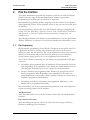
Comdial DXP/DX/FX System
LinkPlus Interface Guide
Link Wireless Telephone System
NetLink Wireless Telephone
Part Number: 72-0171-03
Issue C
SpectraLink Corporation
LinkPlus Interface Guide
Comdial DXP/DX/FX System
Notice
SpectraLink Corporation has prepared this document for use by SpectraLink personnel and customers. The
drawings and specifications contained herein are the property of SpectraLink and shall be neither reproduced in
whole or in part without the prior written approval of SpectraLink, nor be implied to grant any license to make,
use, or sell equipment manufactured in accordance herewith.
SpectraLink reserves the right to make changes in specifications and other information contained in this
document without prior notice, and the reader should in all cases consult SpectraLink to determine whether
any such changes have been made.
The terms and conditions governing the sale of SpectraLink hardware products and the licensing of
SpectraLink software consist solely of those set forth in the written contracts between SpectraLink and its
customers. No representation or other affirmation of fact contained in this document including but not limited
to statements regarding capacity, response-time performance, suitability for use, or performance of products
described herein shall be deemed to be a warranty by SpectraLink for any purpose, or give rise to any liability of
SpectraLink whatsoever.
In no event shall SpectraLink be liable for any incidental, indirect, special, or consequential damages
whatsoever (including but not limited to lost profits) arising out of or related to this document, or the
information contained in it, even if SpectraLink has been advised, knew, or should have known of the
possibility of such damages.
Trademark Information
SpectraLink
The SpectraLink logo
LinkPlus
Link
NetLink
SVP
Are trademarks and registered trademarks of SpectraLink Corporation.
All other trademarks used herein are the property of their respective owners.
SpectraLink Corporation
5755 Central Avenue
Boulder, CO 80301
Within the United States, dial
303.440.5330 or
toll free 800.676.5465
Outside the U.S., dial
+1.303.440.5330
www.spectralink.com
Copyright © 1998 to 2006 SpectraLink Corporation. All rights reserved
Information in this document is subject to change without notice and does not represent a commitment on the
part of SpectraLink Corporation. The software described in this document is furnished under a license and/or
copyright and may only be used with the terms of SpectraLink’s software license agreement as found in this
manual or at http://www.spectralink.com/consumer/resources/software_updates.jsp. The software may be
used only in accordance with the terms of the agreement. No part of this manual, or the software described
herein, may be reproduced or transmitted in any form or by any means, electronic or mechanical, including
photocopying and recording, for any purpose except for the sole intent to operate the product or without the
express written permission of SpectraLink Corporation.
Part Number: 72-0171-03-C.doc
Page 2
SpectraLink Corporation
1.
LinkPlus Interface Guide
Comdial DXP/DX/FX System
About LinkPlus
SpectraLink is the market leader in multi-cellular wireless telephone systems for the
workplace. We manufacture a range of products to suit any installation. All
SpectraLink products use our LinkPlus digital integration technology to integrate
with various digital switch platforms. Using LinkPlus technology, handsets emulate
digital telephone sets to deliver advanced capabilities such as multiple line
appearances and LCD display features. This document explains the programming or
administration required to use the host digital switch with the following SpectraLink
products:
Link Wireless Telephone System (Link WTS)– Link 3000 MCU
The Link WTS 3000 supports up to 3,200 handsets and up to 1,000 Base Stations.
Up to 25 shelves can be interconnected for maximum system capacity.
Link Wireless Telephone System (Link WTS) – Link 150 MCU
Designed for smaller installations supporting up to 64 handsets and up to 16 Base
Stations. Up to four MCU controllers can be interconnected for maximum system
capacity.
NetLink Telephony Gateway
The NetLink Telephony Gateway is a wireless telephony product that provides high
quality packetized voice communications using Internet Protocol (IP).
1.1
Related Documents
Link 3000 MCU: Operator’s Console (72-0059-02)
Link 150 M3 MCU: Installation and Operation (72-0075-01)
NetLink Telephony Gateway: Installation, Configuration, and Administration
(72-0065-02)
NetLink e340/h340/i640 Wireless Telephone: Configuration and Administration
(72-1065-09)
Available at http://www.spectralink.com/consumer/resources/manuals.jsp.
Telephone Switch Interface Matrix (72-0070-10)
Available at http://www.spectralink.com/consumer/resources/interface_guides.jsp.
1.2
Contacting SpectraLink
SpectraLink wants you to have a successful installation. If you have questions please
contact our Customer Support Hotline at (800) 775-5330. The hotline is open
Monday through Friday, 6 a.m. to 6 p.m. Mountain time.
Part Number: 72-0171-03-C.doc
Page 3
SpectraLink Corporation
1.3
LinkPlus Interface Guide
Comdial DXP/DX/FX System
Icons and Conventions
This manual uses the following icons and conventions.
Caution! Follow these instructions carefully to avoid danger.
Note these instructions carefully.
NORM
This typeface indicates a key, label, or button on SpectraLink hardware.
Part Number: 72-0171-03-C.doc
Page 4
SpectraLink Corporation
2.
LinkPlus Interface Guide
Comdial DXP/DX/FX System
Plan the Interface
The system administrator programs the telephone system for use with the Wireless
Telephone System using the normal administration terminal or procedures.
Programming can be done after the handsets are registered.
Recommended programming includes assigning extension numbers to the handsets
and programming features on the telephone system so they are easily accessible from
the handsets.
For analog interfaces, macro codes are in the document relating to configuring the
system. See Link 3000 MCU: Operator’s Console, Link 150 M3 MCU: Installation
and Operation, or NetLink Telephony Gateway: Installation, Configuration, and
Administration.
The following information will help the system administrator set up the SpectraLink
Wireless Telephones to operate in a way that feels familiar and comfortable to users.
2.1
Plan Programming
Digital Interface programming for the Wireless Telephone System will be faster if it
is planned in advance by verifying the parameters and features on the current
telephone system and wired phones. The system administrator must assign extension
numbers to the handsets and plan the functions (trunk access, toll restrictions,
system features, ringing options etc.) to be programmed for the handsets.
One of these scenarios concerning how the handsets are programmed should apply
to this site:
•
All handsets are programmed alike: All handsets will be programmed exactly the
same. Depending on the capabilities of the switch, the system administrator can
often program one handset and use it as a model for all other handsets.
•
Groups of handsets are programmed alike: Handsets are grouped into classes
that are programmed alike. Depending on the capabilities of the switch, the
system administrator can program “model” handsets and then use the model as a
template to program the other handsets.
•
All handsets are different: All handsets are programmed differently, so each
handset will be programmed individually.
Before installation, review the requirements and parameters of the wired telephones
to plan the settings required for the handsets.
Toll Restrictions
These determine which sets are allowed to make outside calls, and which should be
restricted.
Line/Intercom Features
These determine how lines are accessed by users. Note the settings of Idle Line
Preference and Ringing Line Preference.
Part Number: 72-0171-03-C.doc
Page 5
SpectraLink Corporation
LinkPlus Interface Guide
Comdial DXP/DX/FX System
Key-mapping
The handset supports programmable buttons for telephone system features.
Determine which button features, if any, should be programmed on the handsets.
Miscellaneous Features
Note the settings for these station features so the handsets can be programmed the
same way. Check whether All-Call and Zone Paging and SOHVA are used, since
these features will need to be disabled on individual handsets.
If possible, identify a wired set that is programmed exactly the way the handsets
should be programmed, or close to that. This set can be used to copy the
programming to the new handsets.
2.2
Assign Extension Numbers
The wire contractor should inform the system administrator which port numbers
have been designated for the handsets.
The system administrator may use the Extension Assignments Worksheet at the end
of this document to track the port numbers, extensions, users, and features assigned
to handsets.
Part Number: 72-0171-03-C.doc
Page 6
SpectraLink Corporation
2.3
LinkPlus Interface Guide
Comdial DXP/DX/FX System
The SpectraLink Wireless Telephone Display
The handset has a two-line, 16-character alphanumeric display.
Certain characters may be used by the system that are not implemented in the
handset. Flashing characters are not implemented on the handset, nor is rolling or
scrolling of text.
Although some desksets do not have a display, any display information sent by the
system will be displayed on the handset.
Handset Icons
The line indicators are associated with line access keys. The status indicators are
associated with voicemail (MSG), low battery function (BATT), and service interruption
(NO SVC). In addition, a left or right arrow is displayed when the screen can be
toggled either left or right to display more characters as described above.
Link PTB450 Display
When lines are programmed as shown on the key-map diagrams, the numeral icons
on the handset display will be mapped to any deskset LEDs associated with the
corresponding feature keys. The icons will be displayed as follows:
Line State
Handset Line Status Icon State
On-hook
Off
Off-hook
On
Ringing
Fast flash
On hold
Slow flash
Part Number: 72-0171-03-C.doc
Page 7
SpectraLink Corporation
2.4
LinkPlus Interface Guide
Comdial DXP/DX/FX System
Feature Programming Requirements
When planning the interface, the following information must be taken into account:
Line Sequences
The handset uses two types of key sequences to access PBX features and multiple
lines. Line sequences are those where the user presses the LINE button and then a
number button. The key-map design designates “line” keys that should be
programmed for line appearance so that they correspond to line sequences on the
handset.
The LINE icon on the handset will reflect activity on the corresponding deskset key.
For this reason, it is recommended that line appearance keys be used only for line
access. If only one line is assigned to a particular handset, leave unassigned the other
designated line keys identified on the key maps. The corresponding handset Line+
key sequences will then have no function.
Function Sequences
Function sequences are those where the handset user presses the FCN button and
then a number button. Designated “function” deskset keys programmed to system
features such as Transfer and Conference may have their corresponding menu items
display on the handset function menu. See the key map diagram for the function
keys that are available for feature programming.
2.5
Function Menu Programming
Link 3000 MCU
Note that the function menu defaults set for the handsets associated with the Link
3000 MCU can be changed via the SpectraLink Operator’s Console. If the system
uses softkeys, to minimize unwanted interaction between system display and the
handset function menu display, configure the handset menu to include a delay of one
function key. The user will then have to press FCN twice before the handset menu
displays, allowing the first press of the FCN key to access softkey functions. See Link
WTS, Link 3000 MCU: Operator’s Console for further procedural information.
Another option may be to disable the softkey menu at the system level and
exclusively use the SpectraLink menu. This would remove any unwanted interaction,
but might restrict the number of available features to the number of programmable
keys on the handset.
Link 150 MCU
For the Link 150 MCU, the handset function menu can only be changed via remote
configuration through the services of SpectraLink Customer Support.
NetLink Telephony Gateways
Menu options can be changed in the Administration Console of the NetLink
Telephony Gateways. The Delay function is used when the PBX uses softkeys. With
Delay, when the FCN key is pressed, the handset displays the features that are
associated with the softkeys so that one of these features can be selected first. If
Delay is programmed, pressing the FCN key twice will bring up the menus
immediately. Under the menu programming section of the Administration console
Part Number: 72-0171-03-C.doc
Page 8
SpectraLink Corporation
LinkPlus Interface Guide
Comdial DXP/DX/FX System
there is an option to use Delay (same as the Link 3000 MCU). See the NetLink
Telephony Gateway: Installation, Configuration, and Administration document for
further details. Also refer to the same document for details on configuring the
telephone switch type
Hold
The Hold feature should be programmed to the Hold key as shown on the Key-map
Diagrams so that when the HOLD button is pressed on the handset, the call is placed
on hold.
Mute
The handset Mute function is hard-coded in the Link WTS to FCN+1. This function
sequence is recommended, but the system administrator can assign the Mute
function to any available function key sequence or leave the function unassigned.
Voicemail
The message-waiting icon (MSG) on the handset is activated with the message
indication of the deskset. The voicemail feature on the deskset must be assigned to
the feature key as shown in the Key-map Diagrams. Do not assign any other feature
to this key, since the associated LED is directly mapped to the message-waiting icon
on the handset. This LED assignment must be used in order to support the messagewaiting icon. Using this key for any other feature or for line access could cause
unacceptable system performance.
Speakerphone
Because the handset has no speaker, speakerphone function and functions that
require the use of the volume keys will not be made available on the handset.
Intercom
The Intercom button on the 8012S Impact deskset is assigned to the LINE + 9
sequence on the handset.
Ring Types
Handset ring types (soft, normal, vibrate, etc.) are programmed by the handset user
and are not accessible or changeable by the system switch. Whenever possible the
audible ringer on the handset will follow the cadence provided by the system switch.
Call progress tones provided by the host system will be passed through to the
handset.
Part Number: 72-0171-03-C.doc
Page 9
SpectraLink Corporation
3.
LinkPlus Interface Guide
Comdial DXP/DX/FX System
Interface Implementation
This section describes the recommended programming in order to use the
SpectraLink Wireless Telephone System or NetLink components with a Comdial
Digital Telephone System. The procedures assume the following:
3.1
•
The Comdial system system is installed and operational in an approved
configuration. See the Telephone Switch Interface Matrix document for tested
configurations.
•
A trained Comdial technician will be on site with the Installer to program the
system.
•
The Link WTS or NetLink Telephony Gateway is installed and the handsets are
available for programming.
Set the Switch Interface Type
Link 150 MCU
The Link 150 Master Control Unit requires the switch interface type to be
configured using the front panel buttons. The configuration procedures are detailed
in the Link 150 MCU: Installation and Operation document.
Link 3000 MCU
When configuring the Link 3000 MCU, the PBX interfaces are available as sub-menu
selections when defining the Interface Module type using the Link 3000 MCU
Operator’s Console. Refer to the Link 3000 MCU: Operator’s Console document for
details on configuring the Interface Modules.
NetLink Telephony Gateways
Connect to the NetLink Telephony Gateway using the serial or modem interface.
From the Main Menu, choose Gateway Configuration. Scroll to Telephone Switch
Type and press enter to change this field. From the Submenu of PBX types, select
Comdial. Refer to the NetLink telephony Gateway: Installation, Configuration, and
Administration document for details on configuring the Telephone Switch Type.
Part Number: 72-0171-03-C.doc
Page 10
SpectraLink Corporation
3.2
LinkPlus Interface Guide
Comdial DXP/DX/FX System
Key-mapping the handset to Emulate 8012S Functionality
LINE 1
FCN 2/FWD
LINE 2
FCN 3/PICK
LINE 3
FCN 4/PAGE
LINE 4
FCN 5
LINE 5
FCN 6
LINE 6
FCN 7
LINE 7
FCN 8/Exit
Menus
LINE 8
FCN*
FCN 0
FCN #
SHIFT
FCN 9
TRNS/CONF
HOLD
FCN 1
MUTE
FLASH
LINE 9
LINE 0
Comdial 8012S Key-mapping
The FCN [number] and LINE [number] labels represent the key sequence on the
handset mapped to the corresponding key on the desk set. The Shift button + LINE
button on the deskset is used to produce various features. These are accessed on the
handset by using the FCN key plus the number key as shown above.
The handset function menu default settings are shown below; these may be changed
as described above in Function Menu Programming.
FCN + 1
MUTE
FCN + 2
FWD
FCN + 3
PICK
FCN + 4
PAGE
FCN + 8
EXIT MENUS
FCN + 9
TRNS/CONF
Part Number: 72-0171-03-C.doc
Page 11
SpectraLink Corporation
3.3
LinkPlus Interface Guide
Comdial DXP/DX/FX System
Program Comdial
Program the Comdial for use with the SpectraLink Wireless Telephone System using
a PC Terminal Emulator (VDT) or 8012S. Software versions may vary. As you
program, be sure to read the menus and prompts to see that the commands
correspond to the instructions.
As a precaution, the existing programming should be saved to the PC as a binary file.
This can be done from system COS using Xmodem protocol.
Program Handsets
Copy Settings from a Wired Set
If possible, copy the settings from a wired telephone with similar settings and
restrictions to a SpectraLink Wireless Telephone. Once this is done, you can
program the options on one SpectraLink Wireless Telephone, then copy the
programming to other handsets or groups of handsets.
Station Features for Handset
Program the following features for the handsets:
•
Prime Line selects the line that users get when they go off-hook. To give users
an inside dial tone when they go off-hook, assign Intercom as Prime Line.
•
Ringing Line Preference controls the way a station answers a ringing line. To
assign outside lines to display at all handsets, but not ring at all handsets, Disable
Direct Ring.
•
Toll Restrictions control which lines are allowed to make or receive outside
calls. They are programmed through a series of toll tables, which are then
assigned to lines and stations. If you copied an existing wired set, Toll
Restrictions will be set correctly for the handset.
•
The following features should be turned off on handsets:
Line Intercom: Enable Voice Block[formatting of these 3 lines?
SOHVA: Disable
All Call and Zone Paging: Clear
Programmable Buttons
Program the buttons on the handset to correspond with buttons on the wired set.
Copy Programming
After the SpectraLink model Wireless Telephone or handsets have been
programmed, copy the programming to all like SpectraLink Wireless Telephones.
The installer can now test the handsets.
Part Number: 72-0171-03-C.doc
Page 12
SpectraLink Corporation
4.
LinkPlus Interface Guide
Comdial DXP/DX/FX System
Extension Assignments Worksheet
Shelf: _______ Interface Module: _______
Handset #
Ext. #
Name
Interface
Module Circuit
#
Handset 1
1
Handset 2
2
Handset 3
3
Handset 4
4
Handset 5
5
Handset 6
6
Handset 7
7
Handset 8
8
Handset 9
9
Handset 10
10
Handset 11
11
Handset 12
12
Handset 13
13
Handset 14
14
Handset 15
15
Handset 16
16
Part Number: 72-0171-03-C.doc
Comment
Wireless
Handset Serial #
Page 13