1
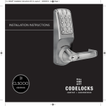
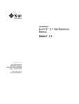
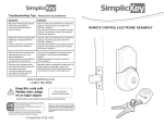
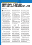
4000/5000 manual_Layout 1 14/01/2013 15:53 Page 1
INSTALLATION INSTRUCTIONS
5OOO
ELECTRONIC
4OOO
ELECTRONIC
4000/5000 manual_Layout 1 14/01/2013 15:53 Page 2
4OOO
Box Contents
Check the contents of the box are
correct according to the model
4010
4020
5010
11 Mortice Latch, Strike and 4 screws
3
3
3
3
3
3
3
3
3
3
3
3
3
-
3
3
3
3
3
3
3
12 Fixing Bolts (Inc spare)
x3
x3
13 Cable Tube and Ring Nut
3
3
3
3
3
3
-
3
3
3
3
3
3
1
Front Plate 4000
2
Front Plate 5000
3
Back Plate 4000
4
Back Plate 5000
5
Back to Back Fixing Plates
6
Lever Handles 4/5000
7
Gaskets (x2)
8
Sprung Spindle
9
Sprung Spindles (x3) – 15/26/60mm (1/2”/ 11/32”/ 23/8”)
5OOO
10 1.5v AA Batteries (x4), (5010BB 8 x 1.5v AAA)
14 Alignment Insert
15 Latch Support Post
16 Allen Keys
17 Cable Connections for REM1 and REM2
18 Front Plate Cylinder Keys
19 Front Plate Cylinder Cover
20 Classroom Function Tailpiece
21 Mortice Lock & Cylinder for 4020/5020
5010BB
5020
3
3
3
3
3
3
3
3
3
3
3
3
-
x4
x4
x4
3
3
3
3
3
3
3
3
-
3
3
3
3
3
3
-
3
3
3
3
3
3
x2
Tools Required
This box should also contain an Installation Template and Programming and Operating Instructions.
2
•Power Drill
• Drill bits 5010
10 (3/8”) & 25mm (1”)
• Drill bits 5020
10 (3/8”), 12 (15/32”), 16 (5/8”) & 20mm (25/32”)
• Hammer / mallet
• Philips screwdriver
• Chisel 25mm (1”)
• Stanley knife
• Adhesive tape, pencil, bradawl, Tape measure
• Pliers and hacksaw for cutting bolts
4000/5000 manual_Layout 1 14/01/2013 15:53 Page 3
21
3
4000/5000 manual_Layout 1 14/01/2013 15:53 Page 4
OPERATIONS CHECK
SPECIAL FIXING NOTE
You should familiarise yourself with the operation of the lock and
check that all parts work properly.
REMOTE RELEASE OPTION
Cables are provided for the REM 1 and REM 2 terminals on the
circuit board. (Fig 1 below).
Remove the battery cover from the back plate and install the 4 x AA
cells supplied.
Connect the cables from the front plate and back plate. A BLEEP
should be heard when you do this. If no BLEEP is heard then check
that the batteries are correctly installed.
Place the long spindle in the front plate socket and using finger grip
only, test that the spindle is easily moved 80o in both directions.
Leave socket in the centred position.
1.
2.
3.
4.
Battery
Remote 1
Remote 2
Clutch/Actuator
Enter the factory Master Code (#1234 for the CL5000) (Badge Bar
1234 for the CL4000).
N.B. When the Master Code is entered 3 times consecutively
without performing a programming function, a penalty time of 10
seconds is activated.
REM 1 is for connection to a reception desk push button or a door
intercom system. Pressing the button will cause the Blue light to
flash on the lock and release the lock for the pre-set time.
The Blue light should flash and the spindle should not turn as
before. After 5 seconds the Red light should flash and the spindle
should turn easily again. This confirms that the clutch engaged
correctly when the code was entered.
REM 2 is for connection to the building alarm system to release a
door in an emergency. This allows rooms, wards, offices to be
easily checked to ensure that no person is trapped or overlooked
during an emergency evacuation. When activated REM 2 will
maintain the unlocked condition for 30 minutes, the Red LED will
flash and BLEEP during this time.
Disconnect the cables.
Turn the key in the front plate cylinder 90o clockwise and confirm
that the spindle will not turn with the key in this position.
Remove the key and confirm that the spindle again turns easily.
This confirms that the key bypass function operates correctly.
For the CL4020 and the CL5020 locks see page 10 to check the
operation of the mortice lock.
4
The lock will automatically lock again after 30 minutes. If
necessary Program 11 can be used to re-lock before the end of the
30 minutes.
REM 1 and REM 2 do not require additional power.They are
normally open contacts requiring a momentary or maintained
signal to close.
4000/5000 manual_Layout 1 14/01/2013 15:53 Page 5
DIMENSIONS
CL4010, CL5010, CL5010BB LATCH FUNCTION
Outside handle turns freely without operating the latchbolt.
When the code is entered the Blue light flashes and the handle will retract the latchbolt.
The latch automatically locks the door when closed.
The key will open the door without the code.
CL4020, CL5020 ANTI-PANIC
LOCK FUNCTION
Outside handle and key functions as
before. Lockcase key will doublethrow the deadbolt, retract the
deadbolt and retract the latchbolt
without the code. When deadbolt is
thrown it denies access by code. The
anti-panic feature allows the inside
handle to simultaneously retract the
latchbolt and the deadbolt preventing
people being accidentally locked in.
5
4000/5000 manual_Layout 1 14/01/2013 15:53 Page 6
INSTALLATION OF CL4010 AND CL5010 LOCKS
Take time to be precise
and finish the job
quicker.
Installation holes must be
drilled in exactly the
correct positions and
precisely at right angles to
the door surface. Lock
components must be
vertically and horizontally
accurate in relation to each
other and to the door.
WEDGE THE DOOR
FIRMLY TO PREVENT
MOVEMENT WHILST
DRILLING AND
CHISELLING.
1 Lightly mark a height line on the edge and both faces of the door and on the door jamb, to indicate the top
of the lock when fitted. Crease the template along one of the dotted lines (60mm (23/8”) or 70mm (23/4”)
latch) and tape it to the door with the top in line with the height line. Mark the holes to be drilled. Mark the
centre line of latch on to the door edge.
Apply the template to the other side of the door precisely against the height line and the centre line of latch
mark. Mark the holes to be drilled again. (See diagram A).
2 Keeping the drill level and straight, drill a 25mm (1”) hole in the centre of the door edge to accept the latch.
3 Keeping the drill level and straight, drill the holes in the door face. Drill from both sides of the door to
increase accuracy and to avoid damage to the other side when a drill goes right through.
4 Put the latch into the hole and, holding it square to the door edge, draw around the faceplate. Starting with
the top and bottom cuts, chisel a rebate to allow the latch face to flush with the door edge. (See diagram B).
5 Fix the latch with the wood screws, with the bevel towards the doorframe.
6 Fit the latch support post on the inside of the front plate, in hole A for a right hand hung door and hole B
for a left hand hung door. (See diagram C).
CL5010 inside
front plate
CL5010
Template
6
4000/5000 manual_Layout 1 14/01/2013 15:53 Page 7
See page 9 for CL5010BB and page 10 for CL4020 and CL5020 Installation Instructions
13 FOR CL5010 LOCKS ONLY.
7 FOR CL5010 LOCKS ONLY.
Check that the spindle turns freely, and the latch retracts and
Screw the cable tube into the front plate, passing the cable through the
projects smoothly, with the alignment insert in place. If it is
tube. For doors less than 45mm (125/32”) thick screw the tube all the
tight, loosen the fixing bolts slightly and adjust the position
way to the end of the thread. For doors more than 45mm (125/32”) leave
of the fixing plate until the spindle will turn freely. Tighten
an appropriate amount of thread showing to accommodate ring nut.
the fixing bolts. Test the spindle again. Do not over-tighten
Example: For a 60mm (23/8”) thick door leave 15mm (3/5”) of thread
the bolts as this may cause the door to distort and affect the
showing.
lock function.
REMOVE THE ALIGNMENT INSERT.
8 Fit the self-adhesive gaskets to the front and back plates. The gaskets
provide friction against the door so that it is not necessary to over14 FOR CL4010 LOCKS ONLY.
tighten the fixing bolts to provide stability.
Remove the battery cover from the back plate, and remove
the battery pack. Apply the front plate over the spindle,
9 FOR CL5010 LOCKS ONLY.
passing the latch support post through the latch and the
Remove the 4 socket head bolts from the back plate (2 are found under
cable through the door. With both parts of the back plate
the battery cover). This will release the inside fixing plate.
together place them over the spindle, pull the cable through,
and screw the fixing bolts through to the front plate.
10 Cut the fixing bolts to correct length. Measured from beneath the bolt
head, the length should be the door thickness, plus approximately
15mm (3/5”) to the nearest cutting point of the bolt.
N.B. Always cut the bolts at one of the cutting points so as not to
damage a thread. Use the cutting edges of pliers to crimp strongly
several times around the selected cutting point. The surplus end
should break off quite easily.
11 Put the spindle into the latch with the spring on the front plate side of
the door.
12 FOR CL5010 LOCKS ONLY.
Apply the front plate over the spindle, passing the cable tube through
the door and the latch support post through the latch. Place the fixing
plate over the cable tube and spindle. Screw the ring nut onto the
cable tube until finger tight. Fit the alignment insert over the spindle.
Screw the fixing bolts through to the front plate. (See diagram D).
CL5010 only
Alignment insert
MUST be removed
before completing
installation.
Continued overleaf
7
4000/5000 manual_Layout 1 14/01/2013 15:53 Page 8
INSTALLATION OF CL4010 AND CL5010 LOCKS CONTINUED
15 FOR CL4010 LOCKS ONLY.
Using the inside handle boss check that the spindle moves freely, and that the latch
retracts and projects smoothly. If it is tight, loosen the fixing bolts slightly and adjust
the position of the back plate until the spindle will turn freely. Tighten the fixing bolts.
Test the spindle again. Do not over-tighten the bolts as this may cause the door to
distort and affect the lock function.
16 Connect the cables, storing any excess cable within the door. Then install the battery
pack.
17 FOR CL5010 LOCKS ONLY.
Fit the back plate over the fixing plate using the 4 socket head screws.
18 Fit the cylinder cover and outside handle to the front plate.
INSTALLATION OF CL5010BB
1 Lightly mark a height line on the edge
and both faces of the door and on the
door jamb, to indicate the top of the lock
when fitted. Crease the template along
one of the dotted lines (60mm (23/8”) or
70mm (23/4”) latch) and tape it to the
door with the top in line with the height
line. Mark the holes to be drilled. Mark
the centre line of latch on to the door
edge.
Apply the template to the other side of
the door precisely against the height line
and the centre line of latch mark. Mark
the holes to be drilled again. (See
diagram A, page 6).
19 Fit the inside handle to the back plate.
20 The inside handle will now retract the latchbolt. The outside handle will turn freely
without retracting the latch. Enter the factory Master Code #1234. The Blue light will
flash and the outside handle will now retract the latch.
21 FITTING THE STRIKE PLATE.
Position the strike plate on the doorframe so that the aperture lines up with the flat of the
latchbolt, and NOT the plunger. Mark the positions of the fixing screws and draw around
the aperture of the strike plate. Chisel out the aperture to 15mm (3/5”) deep to receive the
latchbolt. Fix the strike plate to the surface of the frame using only the top fixing screw.
Gently close the door and check that the latchbolt enters the aperture easily, and is held
without too much ‘play’. When satisfied, draw around the outline of the strike plate,
remove it and cut a rebate to enable the strikeplate to lie flush with the surface. Re-fix
the strike plate using both screws.
N.B. The plunger beside the latchbolt deadlocks it to protect against manipulation or
‘shimming’. The strike plate must be accurately installed so that the plunger CANNOT
enter the aperture when the door is closed, even when it is slammed shut.
8
2 Keeping the drill level and straight, drill
a 25mm (1”) hole in the centre of the
door edge to accept the latch.
3 Keeping the drill level and straight, drill
the holes in the door face. Drill from
both sides of the door to increase
accuracy and to avoid damage to the
other side when a drill goes right
through.
4 Put the latch into the hole and, holding it
square to the door edge, draw around
the faceplate. Starting with the top and
bottom cuts, chisel a rebate to allow the
latch face to flush with the door edge.
(See diagram B on page 6 ).
4000/5000 manual_Layout 1 14/01/2013 15:53 Page 9
5 Fix the latch with the wood screws, with the bevel towards the
doorframe.
6 Fit the latch support post on the inside of the outer front plate, in
hole A for a right hand hung door and hole B for a left hand hung
door. (See diagram C, page 6).
7 The 5010BB is supplied with four AAA cells already fitted to both
sides for your convenience. For future replacement the six
screws on the reverse of each keypad can be removed to gain
access to the battery pack for replacement. Remove the four
transit screws from the installation plates. The plates can now be
fitted to the back of both keypads using the six fixing screws
provided.
8 Fit the self-adhesive gaskets to the front and back plates. The
gaskets provide friction against the door so that it is not
necessary to over-tighten the fixing bolts to provide stability.
9 The 5010BB is supplied with different length bolts to suit various
door thicknesses. The 20mm (25/32”) bolts will suit doors between
35-45mm (13/8”-125/32”) and the 40mm (19/16”) bolts for doors
45-65mm (125/32”-21/2”).
12 Fit the cylinder cover and lever handle to both keypads.
13 Enter the factory Master Code #1234 to test the lock on both
sides of the door. The Blue light will flash and the handle will
now retract the latch. Each unit is stand alone and will need to be
programmed individually.
14 FITTING THE STRIKE PLATE.
Position the strike plate on the door frame so that the aperture
lines up with the flat of the latchbolt, and NOT the plunger. Mark
the positions of the fixing screws and draw around the aperture
of the strike plate. Chisel out the aperture to 15mm (3/5”) deep to
receive the latchbolt. Fix the strike plate to the surface of the
frame using only the top fixing screw. Gently close the door and
check that the latchbolt enters the aperture easily, and is held
without too much ‘play’. When satisfied, draw around the outline
of the strike plate, remove it and cut a rebate to enable the
strikeplate to lie flush with the surface. Re-fix the strike plate
using both screws.
N.B. The plunger beside the latchbolt deadlocks it to protect
against manipulation or ‘shimming’. The strike plate must be
accurately installed so that the plunger CANNOT enter the
aperture when the door is closed, even when it is slammed shut.
10 The lock is supplied with a choice of spindle lengths to use
depending on the thickness of the door. 26mm (11/32”) spindles
will suit doors with a thickness of 38-48mm (11/2”-17/8”). 30mm
(13/16”) spindles will suit doors with a thickness of 45-56mm
(125/32”- 27/32”). 34mm (111/32”) spindles will suit doors with a
thickness of 55-65mm (25/32”-21/2”).
11 Apply the front plate over the spindle and the same with the back
keypad. Then screw the fixing bolts through the installation plate
to the front plate. Place the fixing plate over the spindle.
9
4000/5000 manual_Layout 1 14/01/2013 15:53 Page 10
INSTALLING THE ANTI-PANIC MORTICE LOCK FOR
INSTALLING
THE
ANTI-PANIC MORTICE
MODELS
CL4020 AND
CL5020
LOCK FOR MODELS CL4020 AND CL5020
IMPORTANT The Anti-Panic Mortice Lock has features
which are not found in most other locks and so it is
recommended that you familiarise yourself with them.
1 Lightly mark a height line on the
edge and both faces of the door, and
the door jamb, to indicate the top of
the lock when fitted. Mark a line
down the centre of the door edge,
extending above the height line and
300mm (1113/16”) below it.
The hand of the latchbolt is changed by removing the three
screws holding the faceplate and reversing the latchbolt.
Insert the cylinder centrally in the lockcase and fix in position
with the long bolt through the faceplate.
Using the key it should be possible to double-throw the
deadbolt, retract the deadbolt, and retract the latchbolt.
A
B
C
The latchbolt follower is in 2 parts, with 2 set screws visible
in each part. Determine which side of the lock will be the
outside and remove the set screws from that side. DO NOT
remove the set screws from both sides.
The outside handle will now retract the latchbolt but
NOT the deadbolt.
C
D
E
3 Drill the marked holes 90mm (317/32”)
deep and form the mortice for the
lock.
The inside handle will now simultaneously retract the
latchbolt AND the deadbolt if it is thrown.
This safety feature ensures that it is not possible to
accidentally lock someone in a room by throwing the deadbolt
from outside.
F
F
Throwing the deadbolt will deny access to code users when
appropriate.
All door locks should be installed with a degree of precision
to ensure that all components are horizontally and vertically
accurate in relation to each other, and in relation to the door.
Do not install the lock where it will involve cutting into a joint
between the door stile and a mid-rail.
10
A
B
C
D
E
2 Hold the mortice lock template
against the edge of the door with the
top in line with the height line, and
with the arrows in line with the
‘Centre of Door Edge’ line. Mark the
positions of the fixing screws, and
the holes to be drilled for the
mortice.
Reversible latchbolt
2 part follower
Set Screws
Hole for Codelock fixing bolt
Double-throw
22mm (7/8”) Deadbolt
F Holes for keyhole-cover fixings
4 Fold the template accurately along
the dotted line and tape it to the door
face with the top in line with the
height line, and the fold on the door
edge. Mark the centres of all the
holes to be drilled. Remove the
template and repeat on the other face
of the door.
5 Drill the holes from both faces of the
door to improve accuracy. Do not
drill right through the door as this
will damage the door when the drill
breaks through.
4000/5000 manual_Layout 1 14/01/2013 15:53 Page 11
6 Check that the 2 screws have been removed from the follower
on the outside of the door. DO NOT remove the screws from
both sides of the follower.
13 Position the front plate over the spindle, passing the cable through the
door. Put both parts of the back plate in position with the spindle
engaged in the follower and the cable pulled through.
7 Install the lock case in the door and fit the cylinder. Confirm
that the key will double-throw the deadbolt, retract the
deadbolt, and retract the latchbolt.
14 Pass the top bolt through the door into the front plate, and then the
bottom bolt, to stabilise the assembly.
8 Fit the self-adhesive gaskets to the front and back plates.
The gaskets provide friction against the door so that it is not
necessary to over-tighten the bolts to provide stability.
9 FOR CL5020 LOCKS ONLY.
Remove the 4 socket head bolts from the back plate (2 are
found under the battery cover). This releases the inside
fixing plate.
10 Cut the fixing bolts to the correct length. Measured from
beneath the bolt head the length should be ‘door thickness
plus approximately 15mm (3/5”) to the nearest cutting point of
the bolt.
N.B. Always cut the bolts at one of the reduced sections so
as not to damage a thread. Use the cutting edge of pliers to
crimp strongly several times around the selected cutting
point. The surplus end should break off quite easily.
15 FOR CL5020 LOCKS ONLY.
Position the front plate over the spindle passing the cable through the
door. Then fit the long spindle into the lockcase with spring in place.
Fit the inside fixing plate over the spindle, compressing the spring to
hold the spindle in place, using the 3 pre-cut fixing bolts.
16 Connect the cables.
17 Fit the back plate cover of the CL5020. Fit the batteries and the battery
cover. Fit the cylinder cover and the handles. The inside handle should
retract the latchbolt, and the latchbolt should automatically project again
when the handle is released. With the key turned 90o clockwise the
outside handle should retract the latchbolt.
18 Enter the factory Master Code #1234. The Blue light will flash, and the
handle will retract the latch.
19 Mark a vertical line on the door jamb half the door thickness away from
the door stop. This gives the centre line of the strike plate. Align the
Strike Plate Template with the height line, with the arrow heads aligned
11 According to the door thickness, insert one of the short
with the centre line. Mark the fixing holes, and draw around the
spindles into the outside follower of the lock-case with the
apertures for the latchbolt and the deadbolt. Chisel out the latch aperture
spring facing out. Use the 22mm (7/8”) spindle for doors
to 12mm (1/2”) deep, and the deadbolt aperture to 22mm (7/8”) deep.
between 35-50mm (13/8” - 131/32”), and the 28mm (13/32”)
Fix the strike plate with the top screw only and gently close the door.
spindle for doors between 45-65mm (125/32” - 29/16”). Insert the
Ensure that the latchbolt enters its aperture easily and holds the door
longest spindle into the inside follower with the spring facing out.
without too much ‘play’. When satisfied, draw around the final position
12 FOR CL4020 LOCKS ONLY.
of the strike plate, remove it, and cut a rebate to allow it to fit flush to the
surface. Re-fix the strike with both screws.
Remove the battery cover and the batteries from the back plate.
11
5OOO
4OOO
4000/5000 manual_Layout 1 14/01/2013 15:53 Page 12
ANSI/BHMA
A156.2
A156.25
CODELOCKS LTD - UK
Castle Industrial Park,
Kiln Road, Newbury,
Berkshire, RG14 2EZ.
UNITED KINGDOM
CODELOCKS INC - US
2930 - B College Avenue,
Costa Mesa,
CA 92626.
USA
Tel + 44 (0) 1635 239645
Fax + 44 (0) 1635 239644
[email protected]
Tel +1 714 979 2900
Fax +1 714 979 2902
[email protected]
www.codelocks.com
II-CL4/5000-v1:0113