1
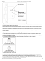
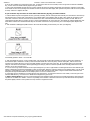
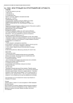
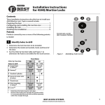
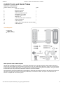
26/09/2013
Codelocks - CL600 Front And Back Plates - Installation
CL600 Front and Back Plates
CL600 Front and Back Plates
Number relating to picture Item
CL600
1
Front Plate and handle
*
2
Back Plate and handle
*
3
Neoprene seals x 2
*
4
RED and BLUE tipped spindles
*
5
Fixing bolts x 3 (1 x spare)
*
6
Front plate cylinder cover
*
7
Allen Keys x 2
*
8
1 pair euro profile cylinder escutcheons
*
8a
Keyhole escutcheons
*
9
Code change keys
*
10
Adaptor kit for mortise locks with horizontal fixings *
11
Code change tool
*
Tools Required
Power Drill
Drill bit 10mm
Philips screwdriver
Check operation of the coded front plate
The code may be entered in any sequence, i.e. 1370 may be entered as 0731 or any other sequence of those numbers. There are a
total of 8,191 codes available, any of which may be entered in any order. The CL600 model is intended to replace the conventional door
furniture fitted to an existing mortise latch, or an existing mortise lock which has both a spring latch and a deadbolt. The square follower
should be 8mm square. Any lock and key mechanism is retained to operate the deadbolt.
The CL600 will only operate the latchbolt and not the deadbolt. A mortise lock case should have holes for fixing bolts to pass through on
either side of the square latch follower and sometimes, additionally, a hole below the follower. See figure 1 and confirm that your
lockcase is compatible with the CL600 lock plates.
www.codelocks.co.uk/products/view/cl600_front_and_back_plates/installation
1/3
26/09/2013
Codelocks - CL600 Front And Back Plates - Installation
IMPORTANT: When using CL600 front and back plates only, please test with your selected locks-case to ensure that the latch retracts
fully from the code side without too much resistance.
Some lock-cases have a heavily sprung latch follower designed for use with un-sprung lever furniture. This heavy springing can defeat
the clutch on our locks.
Please note the code chamber for mechanical locks requires the lever to be rotated at least 45 degrees to re-set the lock for the next
code user.
Please contact Codelocks technical department if you are unsure. Codelocks Limited does not accept responsibility for products
incorrectly specified.
If your lockcase has a hole below the follower (fig.1 ‘A’), proceed as follows:
1. Hold the black neoprene seal against the door, vertically, with the rectangular hole centrally over the follower. Mark the top and
bottom holes on the door face, and repeat the procedure on the other side of the door. Remove the lock. Drill the three 10mm holes
through the door. Drill from both sides for greater accuracy and to avoid splintering out of the door face. Check that the existing spindle
hole is at least 18mm diameter. Fit the lock.
2. Take the BLUE or RED tipped spindle and fit to the code side according to the hand of your door (see diagram).
Fit remaining spindle to inside – non code side.
3. Cut three of the socket head bolts to the required length for your door. Approximate overall length should be door thickness plus
25mm, to allow about 10mm of threaded bolt to enter the outside plate. 4. Remove plastic insert plug from frontplate. Apply the front
and back plates, with the neoprene seals in position, against the door, over the protruding ends of the spindle.
5. Fix the two plates together using the socket head bolts, starting with the top fixing. Ensure that the two plates are truly vertical and
then tighten the bolts using the ‘T’ shaped Allen key. Do not use excessive force.
www.codelocks.co.uk/products/view/cl600_front_and_back_plates/installation
2/3
26/09/2013
Codelocks - CL600 Front And Back Plates - Installation
6. Fit the lever handles to suit the hand of the door. To change the hand of a lever handle, loosen the grub screw with the small Allen
key, reverse the lever handle and fully tighten the grub screw.
7. Ensure that the latchbolt retracts after the code is entered and the lever handle is depressed. Now check the operation of the inside
lever handle. If there is any binding of the handles or latch the loosen the bolts slightly and reposition the plates until the correct position
is found, and then re-tighten the bolts.
If your lockcase only has holes on either side of the follower (fig.1 B), proceed as follows:
1. Hold the black neoprene seal against the door, perfectly vertically, with the rectangular hole centrally over the follower. Mark the top
hole and the holes on either side of the follower, if not already drilled, using adaptor plate as guide, then repeat the procedure on the
other side of the door. Mark an extra hole on the inside of the door in line with the bottom fixing hole. Remove the lock. Drill the 4 x
10mm holes from both sides for greater accuracy, and to avoid splintering out of the door face. Check that the existing spindle hole is at
least 18mm. Drill the extra 12mm hole 5mm deep on the inside of the door to accept the fixing nut on the adaptor plate. Replace the
lock.
2. Take the BLUE or RED tipped spindle and fit to the code side according to the hand of your door (see diagram).
Fit remaining spindle to inside – non code side.
3. Take the adaptor kit, item 9. on the contents table. Cut the two M5 countersunk head bolts to length to suit the door thickness; i.e.
door thickness plus a maximum of 10mm (no more than 5mm should enter the front plate). Hold the front plate, with the three hole
neoprene seal, against the door over the protruding spindle. From the other side of the door, fix the adaptor plate to the front plate
using the two M5 countersunk bolts. Before tightening up the fixings, make sure that the spindle hole is centrally positioned over the
follower. Do not use excessive force.
4. Cut two of the long socket head bolts to the required length for your door. Approximate overall length should be door thickness plus
25mm, to allow about 10mm of threaded bolt to enter the front plate. Place the neoprene gasket over the adaptor plate. Use the screw
with the ‘T’ shaped Allen key, to fix the back plate to the front plate through the TOP holes. Using the 20mm socket head bolt fix the
back plate through the BOTTOM hole to the adaptor plate. Do not use excessive force.
5. Check that the lever handles are correctly fitted for the hand of door. To change the hand of a lever handle, loosen the grub screw
with the small Allen key, reverse the lever handle and full tighten the grub screw.
6. Before closing the door, enter the code and check that the latchbolt retracts when the lever handle is depressed. Now check the
operation of the inside lever handle. If there is any binding of the handles or latch then loosen the top and bottom bolts and reposition
the plates slightly until the correct position is found, and then re-tighten the bolts.
www.codelocks.co.uk/products/view/cl600_front_and_back_plates/installation
3/3