1
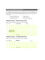
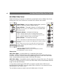
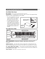
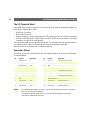
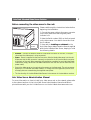
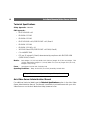
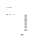
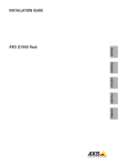
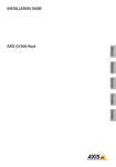
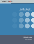
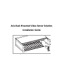
Axis Rack Mounted Video Server Solution
Installation Guide
2
Axis Rack Mounted Video Server Solution
About This Document
This document is intended as an addendum to the video
server Administration Manual. It includes instructions for
installing the Axis Rack Mounted Video Server Solution
on your network. Later versions of this document will be
posted to the Axis Web site, as required.
Intellectual Property Rights - Axis AB has
intellectual property rights relating to technology
embodied in the product described in this document. In
particular, and without limitation, these intellectual
property rights may include one or more of the patents
listed at http://www.axis.com/patent.htm and one or more
additional patents or pending patent applications in the
US and other countries.
Legal Considerations - Camera surveillance can be
prohibited by laws that vary from country to country.
Check the laws in your local region before using this
product for surveillance purposes.
Electromagnetic Compatibility (EMC) - This
equipment generates, uses, and can radiate radio
frequency energy, and if not installed and used in
accordance with the instruction manual, may cause
interference to radio communications. Shielded cables
should be used to ensure compliance with EMC standards.
US - This equipment has been tested and found to
comply with the limits for a Class B digital device,
pursuant to Part 15 of the FCC Rules. These limits are
designed to provide reasonable protection against harmful
interference in a residential installation. This equipment
generates, uses and can radiate radio frequency energy
and, if not installed and used in accordance with the
instructions, may cause harmful interference to radio
communications. However, there is no guarantee that
interference will not occur in a particular installation. If
this equipment does cause harmful interference to radio
or television reception, which can be determined by
turning the equipment off and on, the user is encouraged
to try to correct the interference by one or more of the
following measures: Reorient or relocate the receiving
antenna. Increase the separation between the equipment
and receiver. Connect the equipment into an outlet on a
circuit different from that to which the receiver is
connected. Consult the dealer or an experienced radio/TV
technician for help.
Europe -
This digital equipment fulfills the
requirements for radiated emission according to limit B of
EN55022, and the requirements for immunity according
to EN55024 residential, commercial, and light industry.
Japan - This is a class B product based on the standard
of the Voluntary Control Council for Interference from
AXIS
COMMUNICATIONS
<Product
Name>
Quick
User’s(VCCI).
GuideIf this is used
Information
Technology
Equipment
near a radio or television receiver in a domestic environment,
it may cause radio interference. Install and use the equipment
according to the instruction manual
Australia - This electronic device meets the requirements of
the Radio communications (Electromagnetic Compatibility)
Standard 1998 AS/NZS 3548. Compliance is not valid for
unshielded network cables.
Liability - Every care has been taken in the preparation of
this manual; Please inform your local Axis office of any
inaccuracies or omissions. Axis Communications AB cannot
be held responsible for any technical or typographical errors
and reserves the right to make changes to the product and
manuals without prior notice. Axis Communications AB
makes no warranty of any kind with regard to the material
contained within this document, including, but not limited to,
the implied warranties of merchantability and fitness for a
particular purpose. Axis Communications AB shall not be
liable nor responsible for incidental or consequential damages
in connection with the furnishing, performance or use of this
material.
Trademark Acknowledgments - Acrobat, Adobe, Boa,
Ethernet, IBM, Internet Explorer, LAN Manager, Linux,
Macintosh, Microsoft, Netscape Navigator, OS/2, UNIX,
Windows, WWW are registered trademarks of the respective
holders. Java and all Java-based trademarks and logos are
trademarks or registered trademarks of Sun Microsystems, Inc.
in the United States and other countries. Axis
Communications AB is independent of Sun Microsystems Inc.
Support Services - Should you require any technical
assistance, please contact your Axis reseller. If your questions
cannot be answered immediately, your reseller will forward
your queries through the appropriate channels to ensure a
rapid response. If you are connected to the Internet, you can:
•
•
download user documentation and firmware updates
find answers to resolved problems in the FAQ database.
Search by product, category, or phrases
• report problems to Axis support staff by logging in to
your private support area
Visit the Axis Support Web at www.axis.com/techsup
Warning - This product contains a Lithium battery which is
used to back up the real time clock. This battery lasts more
than 10-15 years. Study the warning notice carefully before
replacing the battery. Do not replace or remove the battery
unless needed! Danger of explosion if battery is incorrectly
replaced. Replace only with the same or equivalent type
recommended by the manufacturer. Dispose of the battery
according to the manufacturer’s instructions.
Axis Rack Mounted Video Server Solution
Installation Guide
Revision 1.10
Date: October 2003
Part No: 21249
Copyright © Axis Communications AB, 2003
Axis Rack Mounted Video Server Solution
3
Axis Video Server Rack will fit up to 12 rack mounted Axis Video Servers (Blade Servers).
This installation guide describes the hardware installation of the Axis Rack Mounted Video
Server Solution. The Axis Video Server Administration Manual contains instructions on
the following:
• Installing the Video Server
• Configuring the video server
• Using the video server
• Troubleshooting
• Updating the software
• Customizing the video server
Hardware Inventory - AXIS Video Server Rack
Please contact your dealer if anything is missing or damaged.
Qty
Item
Product Name/Title
1
Video server rack
AXIS Video Server Rack
5
Cover plates
Cover plate 12TE
1
Cover plate
Cover plate 6TE
2
Connectors
Terminal Connectors 6p
20164
1
Power supply
Power Supply 19” 100W
20683
1
Power Cable
Mains Cable IEC
Country-specific: ensure
that the correct adapter
is used
1
Warranty Document
1
This Document
Country
Part Number
0192-001
Europe
19180
UK
19181
US / Japan
19182
Australia
19183
Axis Rack Mounted Video Server Solution
Installation Guide
21028
Hardware Inventory - Axis Blade Video Server
Please contact your dealer if anything is missing or damaged.
Qty
Item
Title/Variants
Part Number
1
Video servers
AXIS 2400+ Blade
0190-001
AXIS 2401+ Blade
0191-001
Terminal Connectors 14p
20678
2
Connectors
1
Warranty Document
1
Disk Media
AXIS Network Product CD
1
Administration Manual
AXIS Video Server Administration Manual v1.01 or later
1
This Document
Axis Rack Mounted Video Server Solution
Installation Guide
21028
Axis Rack Mounted Video Server Solution
4
Axis Blade Video Server
Read the following information to familiarize yourself with the Axis Blade Video Server
making particular note of where the connectors and indicators are located:
Control Button - Using a suitably pointed object, press this
button to restore the factory default settings.
Power Indicator - The power indicator is lit while power is
applied. If it is not lit, or it flashes, there is a problem with
the power source.
Network Indicator - indicates the following:
• Yellow - indicating network activity on a 10Mbps Ethernet network
• Green - indicating network activity on a 100Mbps Fast Ethernet network
• Red - indicating no physical connection to the network
Status Indicator - indicates the following:
P/N: XXXX-YYY-ZZ
S/N: 00408C1A2B3C
• Green - flashes briefly and momentarily displays orange during the start-up
and self-test routines; the indicator then displays green to indicate a healthy
unit status
• Red - displays red only if there is a problem with the AXIS Video Server
• Orange - flashes orange when resetting to the factory default settings
Product Label -
P/N: XXXX-YYY-ZZ
S/N: 00408C1A2B3C
• P/N (part number) is the product model number.
• S/N (serial number) is identical to the unit’s MAC/Ethernet address.
e.g. 00408c100086 = 00-40-8c-10-00-86
Video In/Out:
AXIS 2400+ Blade - Accommodates up to 4 separate video sources
(VIDEO 1- VIDEO 4) simultaneously. Each supported video input is terminated using a
coax/BNC connector. Physical connections made using RG59 75 Ohm coax video cable
have a recommended maximum length of 800 feet (250 meters).
AXIS 2401+ Blade - Coaxial BNC connector supporting a single video source. The physical
connection is made using RG59, 75 Ohm coax video cable; with a recommended maximum
length of 800 feet (250 meters).
A single video loopthrough (VIDEO OUT) connected in parallel with VIDEO IN and
terminated with a coax/BNC connector allows direct connection of an external monitor.
Set dip switch to OFF when in use.
Top and bottom screws are used to secure the blade server in the rack.
Axis Rack Mounted Video Server Solution
5
Axis Blade Video Server
Bus Connector - Physical interface to the I/O Block Connector on the rack
DIP Switch(es) - A corresponding line termination switch for each of the supported video
outputs (1-4 video outputs depending on the model).
• All units are shipped with the line termination enabled for each supported
video input; that is, with the DIP
switches set to ON. (Down position)
• If the AXIS Video Server is to be connected in parallel with other equipment, disable the input termination by
setting the corresponding DIP switch
to OFF (Up position). Failure to do this
can cause the picture quality to be
impaired
Dip Switch(es)
Bus
Connector
Axis Video Server Rack
DC - Power
(GND)
I/O Terminal Blocks
Power
connector
DC + Power
Network Connectors
The I/O Terminal Block - the physical interface to a relay switch output, four digital
photo-coupled inputs; providing also an RS-485 interface and an RS-232 serial
connection.
Network Connector - Axis blade video servers are designed for 10 Mbps Ethernet /100
Mbps Fast Ethernet networks and connect to the network via a standard RJ 45 connector.
DC + Power 12VDC Power (output) - This connector can drive the photo coupler inputs
or other equipment such as an IR-sensor. A maximum current (for all pins) of 1000mA can
be sourced from the DC output.
Power Connector - Input power: 100-240 VAC, 50-60 Hz, 1.6A
Axis Rack Mounted Video Server Solution
6
The I/O Terminal Block
Axis Blade Video Servers connect to an I/O terminal block used for transmitting data over
multi-drop communication lines:
• RS-485 Pan Tilt devices
• RS-232 Pan/Tilt devices
• External triggering (typically associated with CCTV equipment) COM1 is internally multiplexed
with the RS-485 port via the Terminal Block Connector. COM2 can also be used for connecting
a modem or the AXIS 2191 Audio Module.
The Axis Blade Video Servers support several Pan Tilt device drivers that are selected from
the Administration Tools in the video server’s internal web pages. Please see
www.axis.com for a complete list of supported devices.
Connector Pinout
The pinout for the I/O Terminal Block and the signaling details for each pin are described
in the table below:
Pin
Function
Description
Pin
Function
Description
1
COM2 (RS-232)
RI
15
RS-485-A
Half-duplex RS-485 interface
2
COM2 (RS-232)
CTS
16
RS-485-B
3
COM2 (RS-232)
RTS
17
N/A
4
COM2 (RS-232)
DSR
18
GND
5
GND
19
N/A
6
COM2 (RS-232)
DTR
20
RELAY
7
COM2 (RS-232)
TXD
21
GND
8
COM2 (RS-232)
RXD
22
RELAY
Relay Switch - electrically isolated
from chassis and connectors
9
COM2 (RS-232)
CD
23
Digital Input 4
Photocoupled Input 4
10
GND
24
GND for Digital Inputs
11
COM1 (RS-232)
DSR
25
Digital Input 3
Photocoupled Input 3
12
COM1 (RS-232)
RTS/DTR
26
Digital Input 2
Photocoupled Input 2
13
COM1 (RS-232)
TXD
27
GND for Digital Inputs
14
COM1 (RS-232)
RXD
28
Digital Input 1
Notes:
Relay Switch - electrically isolated
from chassis and connectors
Photocoupled Input 1
For compatible replacement connectors, contact http://www.phoenixcontact.com, quoting:
MC1.5/14-ST-3.81 (art no 1803691)
For further information, please refer to the I/O Terminal Block appendix in the AXIS
2400+/2401+ Administration Manual.
Axis Rack Mounted Video Server Solution
Before connecting the video server to the rack:
Please read through the instructions below before
beginning the installation.
1. Connect the power cable to the power connector
on the rack. Make sure that the green power
indicator is lit.
2. Note the Serial number (S/N) on the front panel
on the video server. You need to know this to set
the IP address.
Power
Indicator
3. Now refer to Installing on a Network in the
Axis Video Server Administration Manual supplied
with the Axis Blade Video Server, keeping in mind
the following details:
• Network - connect the Ethernet cable to the Ethernet connector on the rack, in the position where the video server is to be connected.
• Power - Power is supplied via the Bus Connector, slide the blade video server into the slot.
Make sure that the bus connector is securely connected to the I/O terminal block connector
at the back of the rack. When repeating the installation procedure for each individual blade
video server, simply disconnect the blade video server from the rack (do not disconnect the
power cable).
• Secure the video server to the rack using the screws on the front panel. The rack accommodates up to 12 individual Axis Video Servers. To comply with EMC regulations, ensure that
all empty slots are covered using the supplied cover plates.
• The functionality of the Axis Blade Video Servers is the same as in the standalone versions.
Axis Video Server Administration Manual
For more information on how to install your video server rack on the network, please refer
to the relevant sections in the Axis Video Server Administration Manual available in
printed format with your Axis Video Server or on the Axis Web site at www.axis.com:
7
Axis Rack Mounted Video Server Solution
8
Technical Specifications
Safety Approvals - EN60950
EMC Approvals • EN 55 024:1998 + A1
• EN 61000-6-1:2001
• EN 61000-6-2:2001
• EN 55 022:1998 + A1 (CISPR 22:1997 + A1) Class B
• EN 61000-3-2:2000
• EN 61000-3-3:1995 + A1
• VCCI:2002 Class B ITE (CISPR 22:1997 + A1:2000, Class B)
• C-tick AS/NZS 3548
• FCC part 15, subpart B, Class B, demonstrated by compliance with EN 55022:1998
(CISPR 22:1997) Class B
Metrics - Rack: Height: 5.2" (13.2 cm), Width: 19.0" (48.2 cm), Length: 11.8" (30.0 cm), Weight: 7.3 lb
(3.3 kg). Video Server: Height: 1.2" (3.1 cm), Width: 5.1" (12.9 cm), Length: 10.0" (25.5 cm),
Weight: 0.5 lb (0.23 kg)
Power -
Input Power: 100-240 VAC, 50-60 Hz, 1.6A
Operating Conditions - Temp: 40o to 125oF (5o to 50oC), Humidity: 20-80% RHG.
All specifications are subject to change without prior notice.
Axis Video Server Administration Manual
For additional technical details see the Technical Specifications section in the Axis Video
Server Administration Manual. The Manual is available in printed format with your Axis
Video Server or on the Axis Web site at http://www.axis.com