1
PCOS
SERIES 80PLUS
POS Thermal Printer
PROGRAMMER’S
GUIDE
Rev F
PN: 100-01099
Programmer’s Guide
PcOS Series 80PLUS
Change History
Change History
Rev. F
Added Las Vegas address
Rev. E
Removed ASB. ASB is now a special order option.
Rev. D
Updated disclaimer
Rev. C
Updated contact information
Updated ordering paper section
Rev. B
Clarified Table 1
Updated user defined memory commands
Fixed bar code width table
Rev. A Initial Release
Rev F
Page i
PcOS Series 80PLUS
Programmer’s Guide
Disclaimer
NOTICE TO ALL PERSONS RECEIVING THIS DOCUMENT:
The information in this document is subject to change without notice. No part of this document may be
reproduced, stored or transmitted in any form or by any means, electronic or mechanical, for any purpose,
without the express written permission of TransAct Technologies, Inc. ("TransAct"). This document is the
property of and contains information that is both confidential and proprietary to TransAct. Recipient shall
not disclose any portion of this document to any third party.
TRANSACT DOES NOT ASSUME ANY LIABILITY FOR DAMAGES INCURRED, DIRECTLY OR
INDIRECTLY, FROM ANY ERRORS, OMISSIONS OR DISCREPANCIES IN THE INFORMATION
CONTAINED IN THIS DOCUMENT.
Some of the product names mentioned herein are used for identification purposes only and may be
trademarks and/or registered trademarks of their respective companies.
TransAct, PowerPocket, Magnetec, Insta-Load, POSjet, Ithaca, 50Plus and "Made to Order. Built to Last"
are registered trademarks and BANKjet is a trademark of TransAct Technologies, Inc.
Copyright
© 2005 TransAct Technologies, Inc. All rights reserved.
Revision F
February 2005
Printed in the USA
Page ii
Rev F
Programmer’s Guide
PcOS Series 80PLUS
Change History
Federal Communications Commission Radio Frequency
Interference Statement
The Series 80PLUS Printer complies with the limits for a Class A computing device in accordance with the
specifications in Part 15 of FCC rules which are designed to minimize radio frequency interference during
installation; however, there is no guarantee that radio or television interference will not occur during any
particular installation. If this equipment does cause interference to radio or television reception, which can
be determined by turning the equipment off and on while the radio or television is on, the user is
encouraged to try to correct the interference by one or more of the following measures:
•
•
•
Reorient the radio or television receiving antenna;
Relocate the printer with respect to the receiver;
Plug the printer and receiver into different circuits.
If necessary, the user should consult their dealer or an experienced radio/television technician for additional
suggestions. The user may find the following booklet prepared by the Federal Communications Commission
helpful: How to Identify and Resolve Radio/TV Interference Problems.
This booklet is available from the US Government Printing Office, Washington, DC 20402. Ask for stock
number 004-000-00345-4.
Canadian Department of Communications Radio Interference
Statement
The Series 80PLUS Printer does not exceed Class A limits for radio noise emissions from digital apparatus
set out in the Radio Interference Regulations of the Canadian Department of Communications.
UL, CSA, VDE, CE Statement
TransAct Technologies Incorporated’ printers are UL and CSA Listed, VDE Certified, and carry the CE
Mark.
Declaration of Conformity
Product name:
Type name:
Thermal Printer
Series 80PLUS
These printers conform to the following directives and norms:
Directive 89/336/EEC
EN 55022 (1995) /A1 (1995)
EN 50082-1 (1992)
IEC 801-2 (1991)
IEC 801-3 (1984)
IEC 801-4 (1991)
Directive 90/384/EEC
EN 45501: (1992)
EMI and Safety Standards Applied
Rev F
Page iii
PcOS Series 80PLUS
Programmer’s Guide
The following standards are applied only to the printers that are so labeled. (EMC is tested using the Ithaca
Bestec BPA-601-24-1984).
Europe:
CE marking
EN55022 (1995)
EN50082-1 (1992)
EN45501 (1992)
Safety standard: TÜV EN 60950 (1992)
North America:
EMI: FFC Class A
Safety Standards: UL 1950, 3rd edition (1995)
CAN/CSA-C22.2 No. 950-95, 3rd edition (1995)
WARNING: Warnings must be carefully followed to avoid serious bodily injury.
CAUTION: Care must be taken to avoid minor injury to yourself or damage to your equipment.
NOTES: Notes contain important information and useful tips on the operation of your printer.
Page iv
Rev F
Programmer’s Guide
PcOS Series 80PLUS
Table of Contents
Table of Contents
General Information .................................................................................................................................... viii
Warranty Information ........................................................................................................................... viii
Warranty Options .......................................................................................................................... viii
Service Information....................................................................................................................... viii
What is in this book? ............................................................................................................................ viii
Who should read this book? .......................................................................................................... viii
Where can you find more information?............................................................................................ix
Our Internet Support and Sales Services ..........................................................................................ix
Contacting TransAct Technologies Incorporated.............................................................................ix
Technical Support ............................................................................................................................ix
Sales .................................................................................................................................................ix
TransAct Technologies Incorporated ...............................................................................................ix
General Description..................................................................................................................................1
Features .............................................................................................................................................1
Interface Specifications ............................................................................................................................2
Serial .................................................................................................................................................2
Parallel ..............................................................................................................................................2
Cash Drawer......................................................................................................................................2
Setting up the Printer .......................................................................................................................................3
Connecting the Printer and Computer ......................................................................................................3
Connecting the Cash Drawer ....................................................................................................................4
Connecting the Power Supply ..................................................................................................................6
Self-test Mode .................................................................................................................................................7
Description ...............................................................................................................................................7
Configuration Ticket ................................................................................................................................7
Print Tickets .............................................................................................................................................7
Configuration Mode ........................................................................................................................................8
Description ...............................................................................................................................................8
Entering Configuration Mode...................................................................................................................8
Configuration Options ..............................................................................................................................9
Reference Information ...................................................................................................................................11
Printing Specifications............................................................................................................................11
Paper Specifications ...............................................................................................................................12
Paper roll (single-ply)......................................................................................................................12
Electrical Characteristics ........................................................................................................................12
Reliability ...............................................................................................................................................12
Environmental Conditions ......................................................................................................................12
Control Commands........................................................................................................................................13
Control Codes Overview ........................................................................................................................13
Nomenclature .........................................................................................................................................13
Emulation Modes and Available Commands..........................................................................................14
Standard Emulation .........................................................................................................................14
ESC/POS.........................................................................................................................................14
IPCL Codes ............................................................................................................................................14
Printer Control Codes ....................................................................................................................................15
Print/Paper Motion .................................................................................................................................15
Low-level Paper Motion Control.....................................................................................................15
Horizontal Motion Control .....................................................................................................................16
Vertical Motion Control .........................................................................................................................18
International Character Sets and Code Pages .........................................................................................21
Rev F
Page v
Table of Contents
PcOS Series 80PLUS
Programmer’s Guide
Character Print Control ..........................................................................................................................25
Character Pitch ................................................................................................................................25
Rotated Fonts..........................................................................................................................................27
Character Attribute Commands ..............................................................................................................28
Formatted Print Rotation Commands .....................................................................................................31
Graphics Mode .......................................................................................................................................35
Standard APA Graphics ..................................................................................................................35
Extended APA Graphics .................................................................................................................36
Graphic Save ..........................................................................................................................................38
Programming considerations ...........................................................................................................38
Bar codes................................................................................................................................................40
Printer Control........................................................................................................................................42
M50 Compatibility Commands ..............................................................................................................46
Printer Status Set/Inquire........................................................................................................................47
Serial Mode Inquire.........................................................................................................................47
IEEE 1284 Mode Inquire ................................................................................................................47
Inquire Commands ..........................................................................................................................48
Extended Diagnostic Commands............................................................................................................54
Control Codes Summary by Code ..........................................................................................................55
Epson/Axiohm Commands ............................................................................................................................58
Emulation Modes ...................................................................................................................................58
Supported Commands ............................................................................................................................59
Command Descriptions ..........................................................................................................................63
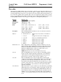
Print and Feed Commands...............................................................................................................63
Line Spacing Commands.................................................................................................................65
User Defined Memory Commands ..................................................................................................66
Character Commands ......................................................................................................................72
Panel Button Commands .................................................................................................................80
Paper Sensor Commands.................................................................................................................80
Print Position Commands ................................................................................................................81
Bit-Image Commands......................................................................................................................85
Status Commands ............................................................................................................................87
Bar code Commands...............................................................................................................................92
Macro Function Commands ............................................................................................................94
Mechanism Control Commands ......................................................................................................96
Miscellaneous Commands...............................................................................................................97
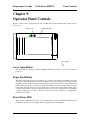
Operator Panel Controls ..............................................................................................................................101
Cover Open Button...............................................................................................................................101
Paper Feed Button ................................................................................................................................101
Power/Error LED .................................................................................................................................101
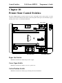
Printer State Control Switches.....................................................................................................................102
Paper Out Switch..................................................................................................................................102
Cover Open Switch...............................................................................................................................102
Cutter Position Switch ..........................................................................................................................102
Troubleshooting...........................................................................................................................................103
Hexadecimal Dump ..............................................................................................................................103
Appendix A .................................................................................................................................................104
Communications...................................................................................................................................104
Overview .......................................................................................................................................104
Interfaces .......................................................................................................................................104
RS-232C Interface.........................................................................................................................104
RTS/CTS Protocol ........................................................................................................................104
DTR/DSR Protocol .......................................................................................................................104
XON/XOFF Protocol ....................................................................................................................105
RS-232C Technical Specification .................................................................................................105
Page vi
Rev F
Programmer’s Guide
PcOS Series 80PLUS
Table of Contents
Parallel Interface ..................................................................................................................................107
Parallel Interface Specification (IEEE 1284) ................................................................................107
Appendix B..................................................................................................................................................108
Error Code Diagnosis ...........................................................................................................................108
Description ....................................................................................................................................108
Appendix C..................................................................................................................................................109
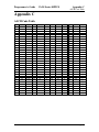
ASCII Code Table................................................................................................................................109
Appendix D .................................................................................................................................................110
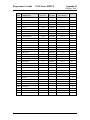
Language Table - Code Page Definitions .............................................................................................110
Appendix E..................................................................................................................................................112
Upgrading/Changing Printer Firmware ................................................................................................112
Appendix F ..................................................................................................................................................113
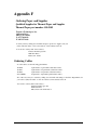
Ordering Paper and Supplies ................................................................................................................113
Ordering Cables....................................................................................................................................113
Rev F
Page vii
Table of Contents
PcOS Series 80PLUS
Programmer’s Guide
Chapter 1:
General Information
Warranty Information
Warranty Options
The PcOS Series 80PLUS Printer comes with a standard 24-month warranty covering both parts and labor.
An optional warranty, covering both parts and labor for an additional 12 months, may be purchased
separately. For more information concerning the warranty options, please contact your dealer or the Sales
Department at TransAct Technologies Incorporated
Service Information
TransAct Technologies Incorporated has a full service organization to meet your printer service and repair
requirements. If your printer needs service, please contact your authorized printer service center. If any
problems still persist, you can directly contact the Ithaca Facility’s Technical Support Department at (607)
257-8901 or (877) 7-ITHACA for a return authorization. International customers should contact your
distributor for services. TransAct offers the following service programs to meet your needs.
Extended Warranty
Depot Repair
Maintenance Contract
Internet Support
Please have the following information at hand:
1. The Model Number and Serial Number.
2. A list of any other peripheral devices attached to the same port as the printer.
3. The application software, operating system, and network you are using.
4. A copy of your printer’s Configuration Settings.
5. What happened and what you were doing when the problem occurred.
6. How you tried to solve the problem.
What is in this book?
Who should read this book?
This book is intended for system engineers or system integrators. It contains the information needed to integrate the
Series 80PLUS Printer with a point-of-sale terminal and to program the terminal to communicate with the printer.
Page viii
Rev F
Programmer’s Guide
BANKjet™ 1500
General Information
Where can you find more information?
Our Internet Support and Sales Services
www.transact-tech.com
TransAct Technologies Inc. maintains an Internet web site with content devoted to product support. Within
the Support Services section you can find the most current versions of the Operator’s Guide and
Programmer’s Guide.
Upon entering our web site, you will be brought to the “Welcome to TransAct” screen. This intro page has
the Ithaca Brand listed at the top right. Click on the Ithaca logo.
Locate and click on the Technical Support button in the green area of the “Welcome to Ithaca” screen.
Use the bottom pulldown box to select the appropriate information for the printer model that you are using.
Contacting TransAct Technologies Incorporated
Contact TransAct’s Ithaca facility for information about the Series 80PLUS Printer and how it works with
your system. For information on international distribution, visit our web site at www.transact-tech.com.
Contact the TransAct’s Sales and Technical Support Departments at the following address and telephone or
fax numbers.
Technical Support
Receive technical support, order documentation, request additional information, or send in a printer for
service.
Sales
Order supplies, receive more product information, or order product brochures.
TransAct Technologies Incorporated
Ithaca Facility
20 Bomax Drive
Ithaca, NY 14850 USA
TransAct Technologies
World Gaming Headquarters
&Western Regional Repair Center
6700 Paradise Road
Suite D
Las Vegas, NV 89119 USA
Telephone
Main fax
Sales fax
Technical Support fax
Web site
(877) 7-ITHACA or (607) 257-8901
(607) 257-8922
(607) 257-3868
(607) 257-3911
http://www.transact-tech.com
Rev F
Page ix
Programmer’s Guide
PcOS Series 80PLUS
General Information
General Description
Features
The Series 80PLUS Printer is a high-quality POS printer that can print on a thermal paper roll. The
printer has the following features.
Printing
•
•
•
•
•
•
High-speed printing: approximately 31.8 lines/second (1/6 inch feed).
Low-noise thermal printing
72-mm/2.83-inch print zone
Dual cash draw drivers with status
Centronics parallel IEEE 1284 nibble, byte mode or RS-232C interface
Configurable receive, and image buffer areas
Software
•
•
•
•
•
•
•
•
Command protocol is based on the Ithaca PcOS Standard.
Characters can be scaled up to 8 times as large as the standard size.
Bar code printing is possible by using a command code. Bar codes can be printed in the
vertical direction.
Repeated operation and copy printing are possible by using graphic save.
Character font size (13 x 24 font or 10 x 24 font) is used to produce 10, 12, 15, 17, and
20 cpi print.
All-points-addressable (APA) graphics are supported in ten different resolutions.
Custom graphic/user save area is located in nonvolatile memory.
Self-diagnostics are included.
Rev F
Page 1
General Information
PcOS Series 80PLUS
Programmer’s Guide
Printer Handling
•
•
•
•
Paper roll loading is easy.
An auto-cutter is standard.
The printer allows easy maintenance for tasks such as head cleaning.
The built-in interface provides control capability for two cash drawers.
Interface Specifications
Serial
The serial interface is a standard RS-232 interface on a 9-pin D-shell connector. It is defined as a
standard DTE device. A null model cable is required to interface the printer to another DTE device
(a PC). See the serial port description contained in the communications area later in this manual for
more information.
Parallel
The parallel port is a standard 25-pin D-shell as defined in the IEEE 1284-A Standard. See the
parallel port description contained in the communications area later in this manual for more
information.
Cash Drawer
The Series 80PLUS printer supports dual cash drawers with status. The interface will provide
status and 24 VDC up to 1.25 amps to the cash drawer. See the cash drawer interface description
later in this manual.
Page 2
Rev F
Programmer’s Guide
PcOS Series 80PLUS
Setting up the Printer
Chapter 2:
Setting up the Printer
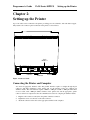
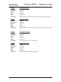
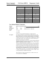
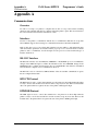
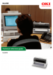
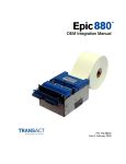
Up to four cables can be connected to the printer, providing power, host interface, and cash drawer support.
They attach to the connector panel on the back of the printer, as shown below.
Cash
Drawer 1
Interface
Cash
Drawer 2
Power
Figure 1 Connector Panel
Connecting the Printer and Computer
You need an appropriate interface cable. The parallel interface requires a straight through 25-pin
connector, with male termination on the printer end, see the interface section for complete pin
definition details. The serial interface requires a DB25- to DB9-pin or DB9- to DB9-pin null modem
crossover cable, with a DB9-pin female terminal on the printer end, and the appropriate gender
connector at the host computer end. See the communication section for complete pin definition details.
1.
2.
3.
Plug the cable connector securely into the printer’s interface connector.
Tighten the screws on both sides of the cable connector.
Attach the other end of the cable to the appropriate terminal on the computer.
Rev F
Page 3
Setting up the Printer
PcOS Series 80PLUS
Programmer’s Guide
Connecting the Cash Drawer
The cash drawer option allows up to two cash drawers to be connected to the printer in a system with a
PC that has no connectors for the cash drawer cables.
The cash drawers are operated by software command from the host system through the printer. For
additional information on the printer commands used by the host system to activate the cash drawers,
see “Control Code Library” later in this manual.
1.
2.
Plug the cash drawer cables into the connectors on the printer. The connectors are standard phone
connectors.
If only one cash drawer is used, plug the cable into the connector labeled 1.
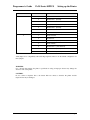
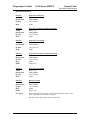
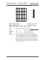
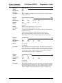
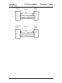
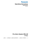
NOTE: The following illustration shows the pin outs for the cash drawer connectors, as viewed from
the rear of the unit. Drawer #2 can be configured to be the same as #1 via jumper J-7.
Drawer 2
123 4 56
Drawer 1
123 4 56
Power Connector
Figure 2 Pin outs for cash drawer connectors
Page 4
Rev F
Programmer’s Guide
PcOS Series 80PLUS
Setting up the Printer
Cash Drawer
J7 3-4* Pin #
Epson/Axiohm
1
1
Frame Ground
2
Drawer Drive - (Ground)
3
Status Switch +
4
Drawer Drive + (24V Switched)
5
Drawer Drive - (Ground)
No Connect
2
6
Status Switch - (Ground)
1
Frame Ground
2
No Connect
Drawer Drive - (Ground)
3
Status Switch +
4
Drawer Drive + (24V Switched)
5
Drawer Drive - (Ground)
6
Status Switch - (Ground)
Table 1
*This jumper is for compatibility with earlier Epson printers. Pins 3-4 are the default configuration for
these jumpers.
WARNING:
Use a drawer that matches the printer’s specification. Using an improper drawer may damage the
drawer as well as the printer.
CAUTION:
Do not connect a telephone line to the drawer kick-out connector; otherwise the printer and the
telephone line may be damaged.
Rev F
Page 5
Setting up the Printer
PcOS Series 80PLUS
Programmer’s Guide
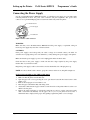
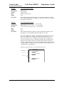
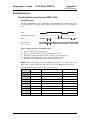
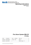
Connecting the Power Supply
Use the optional Ithaca Bestec BPA-601-24-1984 or equivalent power supply for your printer. The
following illustration shows the power cable connector and pin assignments. The power cable
connector is a 3-pin mini-DIN plug and is located in the small cavity under the printer.
Earth Ground
+24 Volt Supply
- 24 Volt Return
Figure 3 Power cable connector
WARNING:
Make sure that you use the Ithaca Bestec BPA-601-24-1984 power supply or equivalent. Using an
incorrect power supply may cause fire or electrical shock.
CAUTIONS:
If the power supply’s rated voltage and your outlet’s voltage do not match, contact your dealer for
assistance. Do not plug in the power cord. Otherwise, you may damage the power supply or the printer.
Make sure that the power supply’s power cord is unplugged from the electrical outlet.
Check the label on the power supply to make sure that the voltage required by the power supply
matches that of your electrical outlet.
Plug in the power supply’s cable as shown below. Notice that the flat side of the plug faces up.
NOTE: To remove the DC cable connector, grasp the connector at the arrow, and pull it straight out.
INSTALLING OR REPLACING THE PAPER ROLL
NOTE: Be sure to use paper rolls that meet specifications.
1. Make sure that the printer is in the idle state.
2. Open the paper roll cover by pressing the cover open button located in the forward corner of the
printer cover.
3. Remove the used paper roll core if there is one.
4. Insert the paper roll with the shiny side facing down.
5. Assure that a small amount of paper extends over the front side of the printer. Then close the cover
until it locks into place.
6. Depress the paper feed button to activate the vertical motor, and toss out the scrap paper. Units
with a cutter will automatically cut the paper off for you, if your printer does not have a
mechanical cutter, simply tear the paper off by pulling it against the printer cover at an angle.
Page 6
Rev F
Programmer’s Guide
PcOS Series 80PLUS
Self-test Mode
Chapter 3:
Self-test Mode
Description
The Series 80PLUS PcOS thermal printer has the ability to print self-test tickets on power-up upon
command. The self-test prints a variety of information about the printer’s operating settings and
configuration. The information provided by the self-test is listed below.
Configuration Ticket
•
•
•
•
•
•
•
•
•
Operating system type and version
Current emulation mode (M50, M80PLUS, Epson TM-T8x, or Axiohm 7193)
Interface configuration
Hex-dump mode status (ON/OFF)
Carriage return control
Input buffer capacity
Graphic save RAM buffer capacity
Nonvolatile EEPROM buffer capacity (bit-image, character set in Epson/Axiohm)
Contents of the EEPROM save buffer (bit-image, character set in Epson/Axiohm)
Start-up macro definition status (YES/NO)
Additional information
Auto-cutter (Enabled/Disabled)
Print Tickets
The configuration ticket is followed by several print examples that test the various features of the
printer.
Rev F
Page 7
Configuration Mode
PcOS Series 80PLUS
Programmer’s Guide
Chapter 4:
Configuration Mode
Description
The Series 80PLUS PcOS thermal printer has many options and features that are user configurable.
Unlike most printers that use dip switches to control these settings, the Series 80PLUS Printer has been
equipped with an automated configuration mode. By powering the Series 80PLUS Printer in a special
sequence, it will enter configuration mode. In this mode, the printer’s current settings are printed one at
a time. By pressing the FEED button, the printer cycles through the remaining available settings for that
option. When the setting for the item you desire has been selected, waiting five seconds will cause the
printer to move on to the next option that you can change. When all options have been exhausted, the
Series 80PLUS Printer writes them permanently to its nonvolatile EEPROM memory and resets itself.
See Configuration Options for an ordered list of options and their associated settings.
Entering Configuration Mode
Follow the steps below to enter the configuration mode:
1.
2.
3.
4.
5.
6.
7.
8.
9.
10.
11.
12.
13.
Power the printer off if it is not already off.
Open the cover.
Power the printer on while holding down the FEED button.
Wait until the status LED blinks a cover open condition. (See Appendix B).
Release the FEED button.
Load the printer with paper if it is not already loaded.
Close the cover.
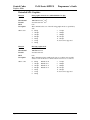
The Series 80PLUS Printer will print a few lines of instructions followed by:
Press PAPER FEED to begin
If the FEED button is not pressed within five seconds, the printer will exit the configuration mode
without making any changes and reset.
If the FEED button is pressed, the printer will start the configuration mode by displaying the first
option and its setting. See Configuration Options for an ordered list of options and their associated
settings.
At this time you may,
A) Press the FEED button to cycle through the choices for this option or
B) Wait five seconds to continue to the next option.
Repeat Step 11 until the last option has been completed.
The Series 80PLUS Printer will print a message indicating it is exiting the configuration mode and
will save the settings exactly as they have been presented/changed.
If the Series 80PLUS Printer is powered off at any time during the configuration mode, no changes will
be saved.
The initial setting displayed with each option reflects the current configuration. If you do not wish to
change a setting, simply wait five seconds to continue to the next option.
The printer does not have to be hooked up to a host computer to use the configuration mode.
Page 8
Rev F
Programmer’s Guide
PcOS Series 80PLUS
Configuration Mode
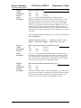
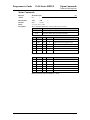
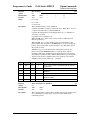
Configuration Options
The tables below depict the options, in order, presented by the configuration mode. Each option shows
the settings available, as well as the default setting where applicable.
Hex Dump Mode
Disabled (default)
Enabled
Emulation Mode
PcOS M80PLUS
M50
Epson TM85
Epson TM88
Axiohm
Carriage Return (CR) Control
Normal return (default)
If hex dump is enabled, the remainder of the configuration process
will be skipped. The printer will then enter hex dump mode. The
printer will remain in hex dump until it is reset or power cycled.
Normal Ithaca M80PLUS Mode (IBM like)
Ithaca M50 Emulation
Epson TM85 Emulation
Epson TM88 Emulation
Axiohm 7193 Emulation
Perform a normal CR by returning the input pointer to the left margin;
overprint allowed.
Translate CR’s into LF’s
Ignore all CR’s; only line feed operations result in print
Line feed
Ignore carriage return
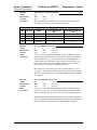
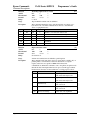
Language Set/Code Page
Selects the default language set/code page depending upon the selected emulation mode.
EURO Substitution
Enabled
Enable Euro character substitution in select code pages.
See Table A below.
Disabled
Auto Cutter Option
Enabled
Disabled
Input Buffer Size
45 bytes
8192 bytes (default)
16384 bytes
24576 bytes
32768 bytes
User Definable Buffer Size
14 KB
RAM buffer storage for user definable character sets and images.
20 KB (default)
1 KB = 1024 bytes
26 KB
32 KB
38 KB
Graphic Buffering
Enabled (default)
The printer will print multiple lines of graphics at the same time.
Start/stop printing will be less noticeable during large images.
Disabled
The printer will print graphics a line at a time.
Rev F
Page 9
Configuration Mode
PcOS Series 80PLUS
Programmer’s Guide
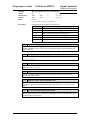
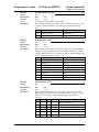
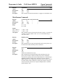
For printers equipped with an RS-232 serial communications interface
Baud Rate
38400 BPS
19200 BPS
9600 BPS (default)
4800 BPS
Data bits, Parity, Stop Bits
8,none,1 (default)
7,odd,1
7,even,1
8,none,2
8,odd,1
8,even,1
Flow Control
XON/XOFF
DTR/DSR
CTS/RTS
CTS/RTS and DTR/DSR
Data Receive Error
Prints ‘?’ (default)
Ignored
Serial Plug and Play
Enabled (default)
Disabled
For printers equipped with an IEEE 1284 parallel communications interface
IEEE 1284 nINIT Line Reset
Enabled (default)
Disabled
IEEE 1284 nACK Signal Operation
Mode 1
Not BUSY precedes ACK low.
Mode 2
Not BUSY follows ACK low.
Name
850
Turkey 857
Win Cyrillic
Win Turkish
Win Greek
Win Hebrew
Win Baltic
Page 10
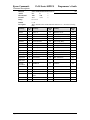
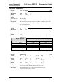
TABLE A: Euro Character Substitution Matrix
Epson
IBM
Code Page Insertion Point
26
850
0xD5
57
857
0xD5
52
1022
0x88
51
1021
0x80
50
1020
0x80
62
1032
0x80
68
1034
0x80
Rev F
Programmer’s Guide
PcOS Series 80PLUS
Reference Information
Chapter 5:
Reference Information
Printing Specifications
Printing method
Dot density
Printing direction
Printing width
Characters per line
Printing speed
Thermal line printing
8 dots/mm x 8 dots/mm (203 dpi x 203 dpi)
Unidirectional with friction feed
72 mm (2.83 in.), 576 dot positions
28 to 57 depending on the selected pitch
Approximately 31.8 lines/second (1/6 inch feed, at 24 V, 20° C)
Approximately 135 mm/second (approximately 5.3 in./second)
NOTES:
Print speed may be slower, depending on the data transmission speed and the combination of control
commands.
The printer switches the mode of the printing speed automatically.
There may be variations in printing after switching the mode of the printing speed.
Paper feed speed
Line spacing (default)
Number of characters
Character structure
Approximately 135 mm/second (approximately 5.3 in./second) continuous
printing
Mode: 4.23 mm (1/6 in.) or 3.17 mm (1/8 in.)
Programmable by control command.
Alphanumeric characters: 255 per code page
International characters: 67 code pages
Font A: 13 x 24 (including 2-dot spacing in horizontal)
Font B: 10 x 24 (including 2-dot spacing in horizontal)
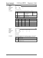
Standard
Font A
13 × 24
Font B
10 × 24
Double-high
1
Double-wide
1
1
WxH
(mm)
1.38 × 3.00
(.06” × .12”)
Cpl
Max
44
WxH
(mm)
1.63 × 6.00
(.06” × .24”)
Cpl
Max
44
WxH
(mm)
2.75 × 3.00
(.11” × .12”)
Cpl
Max
22
1.00 × 3.00
(.04” × .12”)
57
1.00 × 6.00
(.04” × .24”)
57
2.00 × 3.00
(.08” × .12”)
28
Double-wide/
Double-high
1
WxH
Cpl
(mm)
Max
2.75 × 6.00
22
(.11” × .24”)
2.00 × 6.00
(.08” × .24”)
28
Table 2 Character Spacing in Epson and Axiohm Modes
1
cpl = characters per line (Space between characters is not included. Characters can be scaled up to 64
times as large as the standard sizes.)
Rev F
Page 11
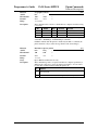
Reference Information
Selected cpi
10
12
15
17
20
1
Actual cpi
10.1
11.9
15.6
16.9
20.3
PcOS Series 80PLUS
1
Font used
A
A
A
B
B
Programmer’s Guide
2
Cpl single-wide
28
33
44
48
57
2
Cpl double-wide
14
16
22
24
28
Table 3 Character spacing in PcOS M80PLUS mode
1
cpi = characters per inch
2
cpl = characters per line
3
Characters can be scaled double-high/double-wide with normal PcOS commands.
Paper Specifications
Paper roll (single-ply)
Maximum outside diameter
Paper roll spool diameter
Inside
Outside
Note
Width
100 mm (4.0 in.)
12 mm (0.47 in.)
18 mm (0.71 in.)
The paper must not be pasted to the paper roll spool.
80 mm +0.0/-1.0 mm (3.15 in. + 0.0/-0.04 in.)
Thermal sensitive layer faces outward on roll.
Electrical Characteristics
Output power
Supply voltage
Amp maximum average
Peak current
Standby current
Line and load regulation
Ripple
Overvoltage protection
48 watts maximum average
24 VDC ± 3% at 2.0 amp maximum average
2.0
4.5 A
0.2 A
± 3% to ± 5% at peak load
240 mV at full load
35 VDV maximum
Reliability
MTBF: Mechanism
Print head life
94,000 hours @ 12.5% ratio
100 km; 100 million pulses
Environmental Conditions
Temperature
Operating
Humidity
Operating
Page 12
0° to 40°C (32° to 104°F)
10% to 90% RH, noncondensing
Rev F
3
Programmer's Guide
PcOS Series 80PLUS
Control Commands
Overview
Chapter 6:
Control Commands
Control Codes Overview
This programmer'
s guide is designed to help users of the PcOS Series 80PLUS Printer develop
applications. The PcOS Series 80PLUS printers are specialized point-of-sale (POS) printers that have
several features not normally found on general purpose printers. Because of these features, the PcOS
Series 80PLUS printers have specialized codes to control these features. This programmer'
s guide
documents the control codes with an emphasis on those codes that are unique to the PcOS Series
80PLUS printer.
All PcOS Series 80PLUS printers are available with both a serial or parallel interface. Both interfaces
provide the same printer control1 and use the same control codes.
Nomenclature
When describing control codes, there is often confusion as to whether the description is decimal, hex,
or ASCII. To minimize this problem, this programmer’s guide will use the following nomenclature
when describing control code sequences:
[]
This encloses a control character and is a single 8-bit value as defined in the standard
ASCII tables. The ASCII table in Appendix C lists all the control codes. An example
would be [ESC] which would represent a 1BH or 26 Decimal.
<>
This encloses an 8-bit value in decimal format. The value will be from 0 to 255. An
example would be <2> which would represent 02H or 2 Decimal.
<n>
This indicates a variable parameter. In this case, a variable parameter, n, can have a value
from 0 to 255. The meaning of n is described and defined in the description of the
command.
<n1> <n2>
This indicates that there are two parameters, n1 and n2, where both have values from 0 to
255.
<m1> <m2> This an IPCL parameter consisting of two digits, where m1 and m2 are ASCII characters
from 0 to 9. The values will be combined to form a value from 0 to 99. If m3 is included,
the parameter will be combined to form a value from 0 to 999.
If two values are specified, there must be two bytes added to the IPCL code. In other
words, if the command specifies <m1> <m2> and the desired value is 5, the value must be
specified as 05.
x
All other characters in control strings represent ASCII characters. For example, [ESC] 1
represents 1BH followed by 31H.
1The serial and IEEE 1284 interfaces provide a few additional interface capabilities over a standard parallel
interface. The parallel M80PLUS supports the IEEE 1284 interface and provides a bidirectional data path.
Rev F
Page 13
Control Commands
Emulation Modes
PcOS Series 80PLUS
Programmer's Guide
Emulation Modes and Available Commands
The Series 80PLUS PcOS thermal printer is capable of emulating an Ithaca M50, Epson TM88, Epson
TM85, and Axiohm 7193 series printer, in addition to the native M80PLUS PcOS. The Ithaca M90
PcOS and M150 PcOS products are supersets/subsets of the M80PLUS. The current emulation mode
can be obtained at any time by performing a self-test and may be changed at any time via the
configuration mode.
Not all of the commands supported by the Series 80PLUS Printer are available at all times.
Standard Emulation
The standard control codes for the PcOS Series 80PLUS printers are extensions and subsets of
other Ithaca PcOS products. In some cases, an application designed for a Series 50 printer with
IBM code sets will function with a PcOS Series 80PLUS Printer in M50 emulation. There are,
however, significant differences in the operation of the PcOS Series 80PLUS Printer that may
impact existing applications.
ESC/POS
The Series 80PLUS printer supports an ESC/POS emulation with Epson or Axiohm emulations.
These commands are different from the PcOS commands and are documented in the
Epson/Axiohm command section of this manual.
IPCL Codes
IPCL (Ithaca Printer Control Language) codes are designed to control a printer without using control
characters (For example, characters less than 20H.) Not all commands are supported by IPCL codes.
For the commands that are, the IPCL code is listed.
In rare cases, an IPCL code will interfere with the text that is to be printed. The IPCL translator can be
disabled with an [ESC]y<4> command.
Page 14
Rev F
Programmer's Guide
PcOS Series 80PLUS
Control Codes
Print/Paper Motion
Chapter 7
Printer Control Codes
Print/Paper Motion
Low-level Paper Motion Control
Function
ASCII
Hexadecimal
Decimal
IPCL
Description
Carriage return
[CR]
0DH
<13>
&%CR
This command prints the contents of the print buffer (if any) and resets the
next character print position to the left margin. A line feed is not performed
unless auto-feed was active. The left margin is defined by the current print
station, print rotation direction, and left margin command.
Function
ASCII
Hexadecimal
Decimal
IPCL
Description
Line feed
[LF]
0AH
<10>
&%LF
This command prints the contents of the buffer (if any) and advances paper
one line at the current default line spacing. The next character print position
is reset to the left margin.
Rev F
Page 15
Control Codes
Horizontal Motion
PcOS Series 80PLUS
Programmer's Guide
Horizontal Motion Control
There are several commands that can control the horizontal position of characters. Many applications
use space control to position fields. However, there is the ability to control character position with
horizontal tab stops. This is done by using the horizontal tab, [HT], to move to those tab stops.
Function
ASCII
Hexadecimal
Decimal
IPCL
Description
Horizontal tab
[HT]
09H
<9>
&%HT
This command inserts spaces in the print buffer up to the next tab stop. The
default tab locations are every eight spaces.
Function
ASCII
Hexadecimal
Decimal
IPCL
Description
Set horizontal tab stops
[ESC] D <n1> <n2> <n3> ... <ni> 0
1BH 44H <n1> <n2> <n3> ... <ni> 00H
<27><68><n1> <n2> <n3> ... <ni> <0>
none
This command sets tab stops at the character columns specified by <n>. The end
of the settings is specified by a <0>. All previously set tabs will be cleared by
this command. There is no restore defaults procedure other than to respecify the
tabs.
Column sizes are in accordance with the current character pitch.
Setting tabs that are beyond the station width is possible. A [CR] will be inserted
if the tab is used. Printing will begin at the home position.
The power up default is every eight spaces, i.e., 9, 17, 25, and so on.
Function
ASCII
Hexadecimal
Decimal
IPCL
Description
Reset horizontal tab stops
[ESC] R
1BH 52H
<27><82>
&%HV
This command resets horizontal and vertical tab stops to power up configuration.
The power up horizontal default is every eight spaces, i.e., 9, 17, 25, and so on.
The vertical default is every line.
Page 16
Rev F
Programmer's Guide
Function
ASCII
Hexadecimal
Decimal
IPCL
Description
Where <n>
PcOS Series 80PLUS
Control Codes
Horizontal Motion
Set justification
[ESC] a <n>
1BH 61H <n>
<27><97><n>
&%JL, &%JC, &%JR
This command sets the horizontal justification. The print format of the printer
can be right, center, or left justified. The value of <n> specifies the justification.
0 = Left justified
&%JL
1 = Center justified
&%JC
2 = Right justified
&%JR
8 = Left justified (No LF)
None
9 = Center justified (No LF)
None
10 = Right justified (No LF)
None
The power on default is left justified.
NOTE: Lines that have mixed size characters within the line cannot be centered.
For example, a line with mixed single- and double-high characters cannot be
centered. If a line of print is to be double-high and centered, the change to
single-high must be done after the line terminator for the double-high line. For
example, [ESC] W<3>Centered[ESC]W<0>[CR] will not print correctly
because the printer assumes that more data will follow the [ESC]W<0>. This
should be: [ESC]W<3>Centered[CR] [ESC]W<0>.
NOTE: The justify commands also effect graphics.
Rev F
Page 17
Control Codes
Vertical Motion
PcOS Series 80PLUS
Programmer's Guide
Vertical Motion Control
Function
ASCII
Hexadecimal
Decimal
IPCL
Description
Fine line feed
[ESC] J <n>
1BH 4AH <n>
<27> <74><n>
&%FM <m1> <m2> <m3>
This command prints the contents of the buffer (if any) and performs a line feed
of n/216 inch. This command does not change the default line spacing value. The
next character print position is reset to the left margin if the Auto-CR mode is
set.
EPOS NOTE: In EPOS mode, this command performs line feeds in n/144-inch
increments.
Function
ASCII
Hexadecimal
Decimal
IPCL
Description
Set variable line space to n/216 inch
[ESC] 3 <n>
1BH 33H <n>
<27><51><n>
&%SV <m1> <m2><m3>
This command sets the default line spacing to n/216 inch. Set n = 1 to 255. This
command sets the line feed spacing used by [LF] to values other than 1/8 or 7/72
inch. This command takes effect immediately as opposed to the [ESC] A <n>
command.
EPOS NOTE: Line spacing of n/144 is used.
Function
ASCII
Hexadecimal
Decimal
IPCL
Description
Set line space 27/216 inch
[ESC] 0
1BH 30H
<27><48>
&%ST
This command sets the default line spacing to 1/8 inch (27/216 inch). This is a
standard 8 lines per inch line spacing. This is the default text line spacing at
initial power-up.
EPOS NOTE: In EPOS mode, this command sets 1/6-inch spacing or 6 lines
per inch.
Function
ASCII
Hexadecimal
Decimal
IPCL
Description
Set line space 21/216 inch or (7/72 inch)
[ESC] 1
1BH 31H
<27><49>
&%SG
This command sets the default line spacing to 21/216 inch. This line spacing is
for all-points-addressable (APA) graphics printing.
Page 18
Rev F
Programmer's Guide
PcOS Series 80PLUS
Control Codes
Vertical Motion
Function
ASCII
Hexadecimal
Decimal
IPCL
Description
Set variable line space n/72 inch
[ESC] A <n>
1BH 41H <n>
<27><65><n>
none
This command sets default line spacing to n/72 inch. Set n = 1 to 85. This line
spacing does not take effect until enabled by the [ESC] 2 command. This
command is provided to maintain backward compatibility with Series 50,
OKIDATA, IBM, and other printers. It can also be used to print on preprinted
forms.
Function
ASCII
Hexadecimal
Decimal
IPCL
Description
Enable [ESC] A <n> line spacing
[ESC] 2
1BH 32H
<27><50>
none
[ESC] 2 enables [ESC] A <n> line spacing. This is a companion to the [ESC] A
<n> command and puts the specified line spacing into effect. It will remain in
effect until another line spacing command is issued.
Function
ASCII
Hexadecimal
Decimal
IPCL
Description
Feed <n> lines at current spacing
[ESC] d <n>
1BH 64H <n>
<27><100> <n>
&%FL <m1> <m2>
This command prints the contents of the buffer (if any) and performs <n> line
feeds at the current line spacing. This command does not change the default line
spacing value. The next character print position is reset to the left margin.
NOTE: The IPCL command will print from 00 to 99 lines. For example, if you
wish to feed 12 lines, the IPCL command would be &%FL12.
Function
ASCII
Hexadecimal
Decimal
IPCL
Description
Form feed
[FF]
0CH
<12>
&%FF
This command performs a form feed to cut.
Function
ASCII
Hexadecimal
Decimal
IPCL
Description
Begin auto line feed
[ESC] 5 <01>
1BH 35H 01h
<27><53><01>
&%MA
This command sets auto line feed mode.
NOTE: This overrides the configuration setting.
Rev F
Page 19
Control Codes
Vertical Motion
Function
ASCII
Hexadecimal
Decimal
IPCL
Description
Page 20
PcOS Series 80PLUS
Programmer's Guide
End auto line feed
[ESC] 5 <0>
1BH 35H 00H
<27><53><0>
&%CA
This command ends auto line feed mode.
NOTE: This command overrides the configuration setting.
Rev F
Programmer's Guide
PcOS Series 80PLUS
Control Codes
International Character Sets
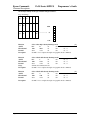
International Character Sets and Code Pages
The PcOS Series 80PLUS Printer supports 65 different international character sets. In IBM and EPOS
printers, there have historically been two ways of selecting a character set. The oldest way is by use of
character sets. This mode substituted international characters in the upper 128 characters of the
standard character set to support different countries. As time passed, this approach became difficult to
support. It became a problem for the application to match the characters displayed and the characters
printed. To solve this problem, code pages were developed. The printer and display would use the same
code page and the application would then display and print the same characters. IBM and EPOS
defined new commands to select code pages and left the old commands in effect.
The PcOS Series 80PLUS Printer supports international character sets as well as code pages. However,
both methods are extended in the PcOS Series 80PLUS. This is to allow the most flexibility for the
application programmer.
The PcOS Series 80PLUS printer has extended the IBM code page selection command to allow
character sets as well as normal IBM code pages to be selected.
All characters in code pages as well as character sets are addressed as 0 to 255. (Characters below 32
must be addressed with the [ESC]^<n> command.) Code pages may be changed at any time and are
active for all features including rotated print.
As discussed above, there are two commands for language selection in IBM mode. The first is [ESC] !
which will select one of 19 international character sets. This command will not select all the possible
sets and is provided for compatibility with older programs. The second is [ESC] [ T which will select
any of the code pages.
Function
ASCII
Hexadecimal
Decimal
IPCL
Description
Select international character table set
[ESC] ! <n>
1BH 21H
<27><33>
&%CS<n>
This command selects the international character set, <n>. In standard mode, the
value of <n> is as follows.
<n>
Language
<n>
Language
<n>
Language
64-’@’ ASCII (Slashed zero)
71-’G’ Norwegian
78-’N’ Swedish IV
65-’A’ ASCII (Unslashed zero)
72-’H’ Dutch
79-’O’ Turkish
66-’B’
British
73-’I’
Italian
80-’P’
Swiss I
67-’C’
German
74-’J’
French Canadian
81-’Q’ Swiss II
68-’D’ French
75-’K’ Spanish
90-‘Z’
Publisher
69-’E’
Swedish
76-’L’
Swedish II
70-’F’
Danish
77 -’M’ Swedish III
Table 4 Language table ID’s
Rev F
Page 21
Control Codes
PcOS Series 80PLUS
International Character Sets
Programmer's Guide
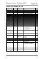
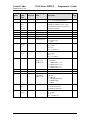
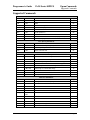
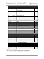
Function
ASCII
Select character code page
[ESC] [ T <nh> <nl>
Hexadecimal
1BH 5BH 54H <nh> <nl>
Decimal
<27><91><84><nh> <nl>
IPCL
&%CP <m1> <m2><m3><m4>
Description
This command selects character code page <nh> <nl>. The PcOS Series 80PLUS
Printer supports many code pages. The following code pages are supported.
Code
Page
Decimal
<nh> <nl>
Hex
<nh> <nl>
Code
Page
Decimal
<nh> <nl>
Hex
<nh> <nl>
0,64
0H,040H
866
0,65
0H,041H
0,66
0,67
0,68
0,69
0,70
0,71
0,72
0,73
0,74
75
76
77
78
USA
(Slashed 0)
USA
(Unslashed 0)
British
German
French
Swedish I
Danish
Norwegian
Dutch
Italian
French
Canadian
Spanish
Swedish II
Swedish III
Swedish IV
Cyrillic II-866
3,98
3H,062H
869
Greek 869
3,101
3H,065H
0H,042H
0H,043H
0H,044H
0H,045H
0H,046H
0H,047H
0H,048H
0H,049H
0H,04AH
874
895
1008
1009
1011
1012
1013
1014
1015
Thailand
Kamenicky (MJK)
Greek 437
Greek 928
Greek 437 Cyprus
Turkey
Cyrillic II-866
Polska Mazovia
ISO Latin 2
3,106
3,127
3,240
3,241
3,243
3,244
3,245
3,246
3,247
3H,06AH
3H,07FH
3H,0F0H
3H,0F1H
3H,0F3H
3H,0F4H
3H,0F5H
3H,0F6H
3H,0F7H
0,75
0,76
0,77
0,78
0H,04BH
0H,04CH
0H,04DH
0H,04EH
1016
1017
1018
1019
3,248
3,249
3,250
3,251
3H,0F8H
3H,0F9H
3H,0FAH
3H,0FBH
Turkish
Swiss I
0,79
0,80
0H,04FH
0H,050H
1020
1021
3,252
3,253
3H,0FCH
3H,0FDH
81
90
91
Swiss II
Publisher
Welsh
0,81
0,90
0,91
0H,051H
0H,05AH
0H,05BH
1022
1024
1026
3,254
4,0
4,2
3H,0FEH
4H,000H
4H,002H
437
774
850
USA
Baltic 774
Multilingual
1,181
3,6
3,82
1H,0B5H
3H,006H
3H,052H
1027
1028
1029
4,3
4,4
4,5
4H,003H
4H,004H
4H,005H
852
East Europe
Latin II-852
Cyrillic I-855
Turkey 857
Portugal
Icelandic-861
Hebrew NC
(862)
Canada French
Norway
3,84
3H,054H
1030
Serbo Croatic I
Serbo Croatic II
ECMA-94
Windows East
Europe
Windows Greek
Latin
(Windows Turkey)
Windows Cyrillic
Hungarian CWI
ISO Latin 4
(8859/4)
Ukrainian
Roman-8
ISO Latin 6
(8859/10)
Hebrew NC (862)
79
80
4,6
4H,006H
3,87
3,89
3,92
3,93
3,94
3H,057H
3H,059H
3H,05CH
3H,05DH
3H,05EH
1031
1032
1033
1034
1035
Hebrew OC
Windows Hebrew
KBL- Lithuanian
Windows Baltic
Cyrillic-Latvian
4,7
4,8
4,9
4,10
4,11
4H,007H
4H.008H
4H,009H
4H,00AH
4H,00BH
3,95
3,97
3H,05FH
3H,061H
1072
Bulgarian
4,48
4H,030H
64
65
66
67
68
69
70
71
72
73
74
855
857
860
861
862
863
865
Country Code/
Language Set
Country Code/
Language Set
Table 5 Code page definition table
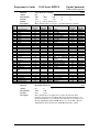
NOTE: The code page field is a 16-bit field that is equivalent to the code page number. For example, 1
* 256 + 181 = 437. For the IPCL command, the page is specified in ASCII as a 4-byte field.
Page 22
Rev F
Programmer's Guide
PcOS Series 80PLUS
Control Codes
International Character Sets
Function
ASCII
Hexadecimal
Decimal
IPCL
Print control character
[ESC] ^ <n>
1BH 5EH <n>
<27><94><n>
&%CC <m1><m2><m3>
Description
This command allows characters from 0 to 31 codes to be printed. During
normal operation, characters from 0 to 31 are control characters. This command
turns off control code translation for the following character. <n> can be from 0
to 255.
Function
ASCII
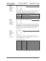
Redefine character set
[ESC] [ S <LL> <LH> <BC> <T1H><T1L> <T2H><T2L> <T3H><T3L> …
<TnH><TnL>
1BH 5BH 40H
<27><91><64>
none
This command allows an application to replace or redefine the active character
set mapping in the printer.
Where <LL> <LH> defines the total length of the following data:
<LL> + 256*<LH> = 1 + 2 * is the total number of characters to be replaced.
<BC> is the first character in the active map to be replaced.
<T1H><T1L>2 is the internal address of the replacement character image.
The mapping of a print pattern to each character address is referred to a code
page or character set. At any given time the printer character set is comprised of
256 characters. Each character is addressed by an 8-bit value generally referred
to as a character code. For example, if you want to print an ‘A’, it would be
addressed by sending a <65> decimal to the printer. There are 65 predefined
code pages or character maps that assign characters to a particular address built
into the printer. However, there are times when an application would like to
redefine a character or group of characters in a code page. To allow this, the
Series 80PLUS Printer allows the map for any code page to be redefined or
replaced. The “Define Character Set” command allows any character or group of
characters to be replaced with any other printable character. There are over 500
printable master characters defined in the printer.
Hexadecimal
Decimal
IPCL
Description
To redefine the character map for the 35th character and replace it with internal
master character 346, the following redefine character set command is used.
[ESC][S <3> <0> <35> <90> <1>
^^^^ ^^ ^^^^^^
|
|
+- 346th Character in Master set
|
|
[(1*256) + 90]
|
+------- 35th Character
+----------- 3 Bytes to follow [(0*256) + 3]
The new map will remain until the printer is power cycled or the character set is
redefined. The code page and character set commands completely redefine this
table.
2
The internal character map is provided in a separate document.
Rev F
Page 23
Control Codes
International Character Sets
Function
ASCII
Hexadecimal
Decimal
IPCL
Description
Page 24
PcOS Series 80PLUS
Programmer's Guide
Insert Euro Character
[ESC] [ C <n>
1BH 5BH 43H …
<27><91><67>
&%EU
This command allows an application to replace any character in the currently
active character set with the Euro character. The character to be replaced is
defined by <n>. For example, if the currently active character set is CP 850
(multilingual) and the 0D5H character is to be the Euro character, “1BH 5BH
43H 0D5H” will replace the character at 0D5H with the Euro symbol.
Rev F
Programmer's Guide
PcOS Series 80PLUS
Control Codes
Character Print
Character Print Control
Character Pitch
Function
ASCII
Hexadecimal
Decimal
IPCL
Description
Begin 10 cpi character pitch
[DC2]
12H
<18>
&%F3
This command sets 10 characters per inch (cpi) print pitch.
Function
ASCII
Hexadecimal
Decimal
IPCL
Description
Begin 12 cpi character pitch
[ESC] :
1BH 3AH
<27><58>
&%F2
This command sets 12 characters per inch (cpi) print pitch.
Function
ASCII
Hexadecimal
Decimal
IPCL
Description
Begin 17 cpi character pitch
[SI]
0FH
<15>
&%F1
This command sets 17 characters per inch (cpi) print pitch
Function
ASCII
Hexadecimal
Decimal
IPCL
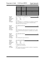
Description
Where n
Set specified character pitch
[ESC] [ P <n>
1BH 5BH 50H <n>
<27> <91> <80> <n>
&%F<n>
This command sets character per inch (cpi) print pitch to <n>.
<10>
selects 10 cpi
&%F3
<12>
selects 12 cpi
&%F2
<15>
selects 15 cpi
&%F6
<17>
selects 17 cpi
&%F1
<20>
selects 20 cpi
&%F5
Rev F
Page 25
Control Codes
Character Print
Programmer's Guide
Function
Mode
ASCII
Hexadecimal
Decimal
IPCL
Description
Set intercharacter spacing
Global
[ESC] V <n>
1BH 56H <n>
<27> <86> <n>
none
This command sets intercharacter spacing by adding white space between
characters. The value of <n> sets the spacing and can range from 0 to 256.
The normal pitch set commands set the intervalue to 0. Each value of n adds
1/180 inch to the space between characters.
Function
ASCII
Hexadecimal
Decimal
IPCL
EPOS
Description
Set left/right print margin
[ESC] X <n1> <n2>
1BH 58H <n1> <n2>
<27><88> <n1> <n2>
none
[ESC]l, [ESC]Q
This command sets left and right print margins in characters from the home
position.
n1 = Left margin
n2 = Right margin
The absolute position depends on the current print pitch.
This command should be issued at the start of a new line. If it is not, the
previous data will be printed, and this command will take effect on the next
line.
Where
Page 26
PcOS Series 80PLUS
Rev F
Programmer's Guide
PcOS Series 80
Control Codes
Rotated Fonts
Rotated Fonts
Function
ASCII
Hexadecimal
Decimal
IPCL
Description
Where
Begin 90°° or 270°° rotated font
[ESC] P <n>
1BH 50H nH
<27><80><n>
&%RI {n=2},&%RF{n=1},&%RN{n=0}
This command sets the print font to a rotated 90° or 270° font.
n=0
Normal
n=1
Rotate 90°
n=2
Rotate 270°
n=5
Rotate 90°
n=6
Rotate 270°
The rotated print font is a 1 pass 7 x 9 or 5 x 7 font. Enhanced, emphasized,
subscript, superscript, and underline character attributes are not available in this
mode. Double-wide and double-high fonts are available. However, because the
font is rotated, double-wide font will make the characters taller and double-high
font will make the characters wider.
The current pitch sets the spacing between lines. If 8 cpi is set, the printer will
produce the equivalent of 8 lines per inch rotated print. Print pitches greater than
15 cpi are very small and difficult to read.
This mode prints faster than the formatted, rotated print mode. However, no
formatting is available in this mode.
Function
ASCII
Hexadecimal
Decimal
IPCL
Description
End 90°° rotated font
[ESC] P <0>
1BH 50H 0H
<27><80><0>
&%RN
This command returns the print font to normal nonrotated mode.
NOTE: This command leaves the printer in utility print mode.
Rev F
Page 27
Control Codes
Character Attributes
PcOS Series 80PLUS
Programmer's Guide
Character Attribute Commands
Function
ASCII
Hexadecimal
Decimal
IPCL
Description
Begin one-line double-wide print
[SO]
0EH
<14>
&%MW
This command causes subsequent characters to be printed at twice the currently
selected character width. For example, 10 cpi becomes 5 cpi, 17 cpi becomes 8.5
cpi, and so on. This command will remain in effect until:
A. A valid line terminator is received (CR, LF, or fine line feed);
B. The command is canceled; or
C. The maximum number of characters per line is reached, and the printer
performs an auto print.
Function
ASCII
Hexadecimal
Decimal
IPCL
Description
Cancel one-line double-wide print
[DC4]
14H
<20>
&%MN
This command cancels one-line double-wide mode set by the [SO] command and
allows single- and double-wide characters to be printed on the same line.
Function
ASCII
Hexadecimal
Decimal
IPCL
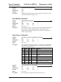
Multiline, double-wide, and double-high print
[ESC] W <n>
1BH 57H <n>
<27><87><n>
&%FD, &%FS, &%FH
NOTE: Single-wide, double-high mode is not available in IPCL.
This command controls multiline double-wide or double-high mode.
n
Specifies the mode
0
Standard single-wide and single-high
&%FS
1
Begin double-wide
&%FD
2
Begin double-high
None
3
Begin double-wide and double-high
&%FH
NOTE: This command does not affect line spacing.
Description
Where
Page 28
Rev F
Programmer's Guide
Function
ASCII
Hexadecimal
Decimal
IPCL
Description
PcOS Series 80PLUS
Control Codes
Character Attributes
Set print style: double-wide, double-high
[ESC] [ @ [EOT] [NUL] <k> [NUL] <n> <m>
1BH 5BH 40H 04H 00H <k> 00H <n> <m>
<27><91><64> <04> <0> <K> <0> <n> <m>
&%DH Double-high, double-wide, and double-space
&%SH Single-high, single-wide, and single-space
Also, see [ESC] W above.
This command sets double-wide and double-high print mode.
Where k-bits 76543210
0
----0000
No change
Where n-bits 76543210
----xxxx
Height multiplier
0
----0000
No change
1
----0001
Single-high
2
----0010
Double-high
xxxx---Line spacing
0
0000---No change
16
0001---Single line feed
32
0010---Double line feed
Where m-bits 76543210
----xxxx
Width multiplier
0
----0000
No change
1
----0001
Single-wide
2
----0010
Double-wide
Function
ASCII
Hexadecimal
Decimal
IPCL
Description
Begin underline
[ESC] - <1>
1BH 2DH 01H
<27><45><1>
&%MU
This command begins underline print mode. All subsequent text and leading
spaces will be underlined. Trailing spaces are also underlined.
NOTE: Underline is not available in High Speed Draft mode.
Function
ASCII
Hexadecimal
Decimal
IPCL
Description
End underline
[ESC] - <0>
1BH 2DH 00H
<27><45><0>
&%CU
This command ends underline print mode.
Rev F
Page 29
Control Codes
Character Attributes
PcOS Series 80PLUS
Programmer's Guide
Function
ASCII
Hexadecimal
Decimal
IPCL
EPOS
Description
Begin enhanced print
[ESC] G
1BH 47H
<27><71>
&%ME
[ESC] G <1>
All subsequent text will be printed in an enhanced (darker looking) print mode.
Function
ASCII
Hexadecimal
Decimal
IPCL
EPOS
Description
End enhanced print
[ESC] H
1BH 48H
<27><72>
&%CE
[ESC] G <0>
This command cancels enhanced print mode and returns to the currently selected
font.
Function
ASCII
Hexadecimal
Decimal
IPCL
EPOS
Description
Begin emphasized print
[ESC] E
1BH 45H
<27><69>
&%MM
[ESC] E <1>
This command is the same as enhanced print.
Function
ASCII
Hexadecimal
Decimal
IPCL
EPOS
Description
End emphasized print
[ESC] F
1BH 46H
<27><70>
&%CM
[ESC] E <0>
This command cancels emphasized print mode.
Page 30
Rev F
Programmer's Guide
PcOS Series 80PLUS
Control Codes
Formatted Print Rotation
Formatted Print Rotation Commands
To provide flexibility in printing various sized forms, rotated print capability is provided. This mode
will rotate the print in any of three 90° orientations.
In 90° and 270° rotated mode, the print data is first buffered by the printer, processed (rotated) and
then printed. This causes the print process to be delayed slightly as it takes some time to process the
data before it is printed. In 180° mode, the print is simply inverted and mirrored.
Because the 90° and 270° rotated print buffer is limited, the amount of rotated print is also limited. The
printer can support a limit of 23 lines of rotated print with a maximum line length of 128 characters.
The spacing between lines is controlled by a line spacing table. This table is defined by the rotated print
line spacing ([ESC] u ...) command or by inserting [LF] or [ESC]J<n> commands in the rotated data.
The [ESC]u command specifies the space to be added between each printed line. Each line has an entry
in the table. There is room for 23 lines in the table. The minimum spacing (and default) is 1/80 inch
between lines.
If a [LF] is used to specify the line spacing, it overrides the default table and sets spacing to 1/80 inch.
If [ESC] J <n> is used, <n> specifies the spacing in n/216 inch (including white space).
The intercharacter spacing is adjusted with the normal line spacing commands. The [ESC]3<n>
command is the most effective command for adjusting intercharacter spacing.
Specifying the line length is useful to determine where data is printed if line formatting is specified.
When rotated 90° and 270°, the print field can be extended to print the complete line length specified.
This mode is called line formatted mode. In line formatted mode, the line length is set not by the
longest line entered but by the set line-length command. The default line length is 80 characters,
However, any value from 1 to 128 may be selected. Anything past the selected length will be wrapped
to the next line.
In rotated 180° mode, all spacing commands are effective. This mode of operation simply inverts and
mirrors the print operation. All line spacing and print features are available. It should be noted that the
feed direction is not effected by any of the rotate commands.
Rev F
Page 31
Control Codes
Formatted Print Rotation
Function
ASCII
Hexadecimal
Decimal
IPCL
EPOS
Description
PcOS Series 80PLUS
Programmer's Guide
Begin rotated print
[ESC] r <X>
1BH 72H 0XH
<27><114><X>
&%RX
[ESC] T <3>
This command starts rotated print mode where X defines the mode as follows:
n-bits
76543210
Function
----xx00
End rotated print
----xx01
Rotate 90°
----0010
Rotate 180°
----xx11
Rotate 270°
----x1xx
Use line formatting
If X = 1 or 9, rotate print mode by 90°. Print data is entered normally from left to
right, top to bottom. When an End Rotated Print ([ESC] r <0>) command is
received, the printer will format and print the data.
If X = 5 or 13, rotate print mode 90° with formatting. This command differs
from the [ESC] r <1> command in that the line length is determined not by the
longest line entered, but by the line length set by the [ESC] s command. If input
extends past the end of a line, the print will line wrap.
If X = 3 or 11, 270° rotated print mode is entered. The print will be rotated 270°
according to the currently stored format parameters.
If X = 7 or 15, 270° rotated print mode is entered. The print will be rotated 270°
according to the currently stored format parameters. This command differs from
the [ESC] r <3> command by spacing out the lines to the line length specified by
the [ESC] s command. If input extends past the end of a line, the print will line
wrap.
If X = 2, 180° rotated print mode is entered. All subsequent lines will be rotated
180° and positioned at the opposite margin. All normal fonts and modes are
available in 180° rotated mode. The format and font bits are ignored by this
command. This command will remain in effect until rotation is canceled with an
End Rotated Print ([ESC] r <0>) command, or a station select command is
issued.
Page 32
Rev F
Programmer's Guide
PcOS Series 80PLUS
Control Codes
Formatted Print Rotation
Rotated Print Summary:
Function
ASCII
Hexadecimal
Decimal
IPCL
Begin 90°° rotated print
[ESC] r <1>
1BH 72H 01H
<27><114><1>
&%R1
Function
ASCII
Hexadecimal
Decimal
IPCL
Begin 90°° rotated print with line formatting
[ESC] r <5>
1BH 72H 05H
<27><114><5>
&%R5
Function
ASCII
Hexadecimal
Decimal
IPCL
Begin 270°° rotated print
[ESC] r <3>
1BH 72H 03H
<27><114><3>
&%R3
Function
ASCII
Hexadecimal
Decimal
IPCL
EPOS
Begin 270°° rotated print with line formatting
[ESC] r <7>
1BH 72H 07H
<27><114><7>
&%R7
[ESC] T <1>
Function
ASCII
Hexadecimal
Decimal
IPCL
Begin 180°° rotated print
[ESC] r <2>
1BH 72H 02H
<27><114><2>
&%R2
Function
ASCII
Hexadecimal
Decimal
IPCL
EPOS
Description
End rotated print
[ESC] r <0>
1BH 72H 00H
<27><114><0>
&%R0
[ESC] { <0>
This command prints the contents of the rotated print buffer (if 90° or 270°
mode) and returns to normal print orientation.
In 180° mode, the printer will return to normal mode.
Rev F
Page 33
Control Codes
PcOS Series 80PLUS
Formatted Print Rotation
Programmer's Guide
Function
ASCII
Hexadecimal
Decimal
IPCL
EPOS
Description
Set rotated print line length
[ESC] s <n>
1BH 73H <n>
<27><115><n>
&%RL <m1> <m2><m3>
none
This command sets the print line length to be used in auto-format rotated print
mode. The maximum number of characters is 128 per line. The power on default
line length is 80 characters.
Function
ASCII
Hexadecimal
Decimal
IPCL
EPOS
Description
Set rotated print line spacing
[ESC] u <n1> <m1> <n2> <m2> ... <ni> <mi> <0>
1BH 75H <n1> <m1> <n2> <m2> ... <ni> <mi> 00H
<27><117> <n1> <m1> <n2> <m2> ... <ni> <mi> <0>
none
none
This command adjusts line spacing for each rotated print line. Where ni is the
line number, mi is the spacing in 1/80 inch from the previous line.
For the first print line, the distance is calculated from the margin. An ni value of
0 is used to terminate the command. Any unspecified spacing will be set to 1.
These values will be used as a template for all subsequent, rotated print. On
power up, all spacing is preset to 1/80 inch for all lines. This command is only
effective in 90° and 270° rotation. It will remain in effect until a new table is
received or until the printer is power cycled. An [ESC] u <0> will have the effect
of setting all lines to 1. This table can be overridden by an [LF] or [ESC] J <n>
command in the rotated print data.
The value of m can be from 1 to 127; n can be from 1 to 23.
Edge Receipt
Left Margin
First line
n=1, m
Second Line
n=2, m
Third Line
Page 34
Rev F
Programmer's Guide
PcOS Series 80PLUS
Control Codes
Graphics Mode
Graphics Mode
The PcOS Series 80PLUS Printer conforms to the general definitions of IBM APA graphics. The
printer will only print graphics that are 2.83 inches wide. This can make it difficult to use off-the-shelf
graphic generation programs.
If the PcOS Series 80PLUS Printer is used with programs that convert text to graphics, the printer will
be slower than if the printer is sent ASCII text. The PcOS Series 80PLUS Printer is supported by a
Windows print driver that will allow applications to select fonts that are supported by the printer.
The Series 80PLUS Printer maps all APA graphic modes to the native 200 dpi resolution of the printer.
These commands are provided to allow existing applications to print graphics.
Standard APA Graphics
Function
ASCII
Hexadecimal
Decimal
IPCL
Description
dpi).
Function
ASCII
Hexadecimal
Decimal
IPCL
Description
Function
ASCII
Hexadecimal
Decimal
IPCL
Description
Function
ASCII
Hexadecimal
Decimal
IPCL
Description
Print single-density graphics (60h x 72v dpi)
[ESC] K <n>1 <n>2
1BH 4BH <n>1 <n>2
<27><75><n>1 <n>2
none
This command prints n1 + 256 * n2 bytes of single-density graphics (60
Print half-speed double-density graphics (120h x 72v dpi)
[ESC] L <n>1 <n>2
1BH 4CH <n>1 <n>2
<27><76><n>1 <n>2
none
This command prints n1 + 256 * n2 bytes of double-density graphics (120
dpi) at half speed, allowing full and half dots to be printed.
Print full-speed double-density graphics (120h x 72v dpi)
[ESC] Y <n>1 <n>2
1BH 59H <n>1 <n>2
<27><89><n>1 <n>2
none
This command prints n1 + 256 * n2 bytes of double-density graphics (120
dpi) at full speed, no consecutive dots. (This mode is generally used to print
120h by 144v dpi resolutions in two passes)
Print quad-density graphics (240h x 72v dpi)
[ESC] Z <n>1 <n>2
1BH 5AH <n>1 <n>2
<27><90><n>1 <n>2
none
This command prints n1 + 256 * n2 bytes of quad-density graphics (240
dpi) at full speed with consecutive dots. (This mode is generally used to
print 240h by 144v dpi resolutions in two passes)
Rev F
Page 35
Control Codes
Graphics Mode
PcOS Series 80PLUS
Programmer's Guide
Extended APA Graphics
Function
ASCII
Hexadecimal
Decimal
IPCL
Description
Where <m>
Function
ASCII
Hexadecimal
Decimal
IPCL
Description
Where <m>
Page 36
Print graphics in mode <n> (60h/120h/240h x 72v dpi)
[ESC] * <m> <n>1 <n>2
1BH 2AH <m><n>1 <n>2
<27><42><m><n>1 <n>2
none
This command selects one of the following graphic modes as specified by
<m>.
0 60 dpi
7 144 dpi
1 120 dpi
8 100 dpi
2 120 dpi
9 200 dpi
3 240 dpi
10 101 dpi
4 80 dpi
11 203 dpi
5 72 dpi
12,13,14,16 not supported
6 90 dpi
Reassign graphic mode
[ESC] ? <m> <n>
1BH 3FH <m><n>
<27><63><m><n>
none
This command reassigns graphic mode <m> to resolution <n>. Possible
values for <m> are K, L, Y, or Z. Resolutions <n> are 0 to 7 as follows:
0 60 dpi
Default for K
7 144 dpi
1 120 dpi Default for L
8 100 dpi
2 120 dpi Default for Y
9 200 dpi
3 240 dpi Default for Z
10 101 dpi
4 80 dpi
11 203 dpi
5 72 dpi
12,13,14,16 not supported
6 90 dpi
Rev F
Programmer's Guide
Function
ASCII
Hexadecimal
Decimal
Description
Where m
PcOS Series 80PLUS
Control Codes
Graphics Mode
Print single-density graphics
[ESC] * <m> <n>1 <n>2
1BH 4BH <n>1 <n>2
<27><75><n>1 <n>2
This command prints n1 + 256 * n2 bytes of graphics where m specifies the
density.
0 Single-density graphics (60 dpi)
1 Double-density graphics (120 dpi)
2 Double-density half-speed graphics (120 dpi)
3 High-density graphics (240 dpi)
4, 5 CRT II Screen (72 dpi)
6 CRT I Screen (90 dpi)
7 Dual plotter (144 dpi)
8 100 dpi
9 200 dpi
10 101 dpi
11 203 dpi
Rev F
Page 37
Control Codes
Graphic Save
PcOS Series 80PLUS
Programmer's Guide
Graphic Save
The PcOS Series 80PLUS Printer contains a graphic save buffer. This buffer is 24K bytes long and can
be saved in the printer’s nonvolatile memory. The nonvolatile memory is read at power up and is
available to be printed with a single command. The purpose of this feature is to allow a graphic logo to
be stored in the printer and printed on command.
The buffer is intended to save a graphic image. However, any print information can be saved and then
reprinted. The print information in this buffer can be replaced at any time and then reprinted. It does
not need to be saved in the nonvolatile memory. It is feasible for the buffer to be used to create a
duplicate receipt.
Programming considerations
This feature works by inserting the save graphic buffer into the printer data stream when the print
graphic save command is encountered.
Some care should be taken when forming this buffer. Because when this buffer is inserted, any
configuration commands (like font or pitch changes) will remain in effect after the buffer is
complete and/or printed.
The nonvolatile memory has a limited number of write-cycle operations. For this reason, the
number of saves should be limited. The buffer should not be saved on a transaction by transaction
basis. Once a day should be the limit.
The buffer is 24K bytes long. All commands3 and print data are placed in the buffer and both must
be included in the 24K limit. There is no indication by the printer when it is full. The application
must make sure that the buffer is not overfilled. The printer will simply stop saving information in
the buffer after 24K characters are received.
As the buffer is filled, the input data is printed normally. The effect of the graphic save start
command is to start to save the input data. The graphic save stop command stops saving data and
initializes internal pointers for the next print. The graphic save "stop and save" command stops the
save, writes the buffer to the nonvolatile memory, and then initializes the internal pointers for the
next print. The graphic save print command inserts the buffer into the print stream after the graphic
save print command.
3 IPCL commands are converted by the printer into an equivalent [ESC] code and then placed in the save
buffer. The equivalent [ESC] code should be used to calculate the size of the save buffer data.
Page 38
Rev F
Programmer's Guide
PcOS Series 80PLUS
Control Codes
Graphic Save
Function
ASCII
Hexadecimal
Decimal
IPCL
EPOS
Description
Graphic save print
[ESC] g <0>
1BH 67H 00H
<27><103><0>
&%GP
[ESC] g <0>
This command prints the graphic save buffer.
Function
ASCII
Hexadecimal
Decimal
IPCL
EPOS
Description
Start graphic save record
[ESC] g <1>
1BH 67H 01H
<27><103><1>
&%GS
ESC] g <1>
This command clears the graphic save buffer and starts recording data. The
next 24K bytes (including characters and commands) will be recorded.
Function
ASCII
Hexadecimal
Decimal
IPCL
EPOS
Description
Stop graphic save record
[ESC] g <2>
1BH 67H 02H
<27><103><2>
&%GE
[ESC] g <2>
This command stops recording graphic save information. The buffer is not
saved into nonvolatile memory.
Function
ASCII
Hexadecimal
Decimal
IPCL
EPOS:
Description
Stop graphic save record and save
[ESC] g <3>
1BH 67H 03H
<27><103><3>
&%GW
ESC] g <3>
This command stops recording graphic save information. The buffer is
saved into nonvolatile memory.
NOTE: The printer will remain busy for about seven seconds after this
command. This time is required to erase and resave the graphic save buffer
into the nonvolatile memory.
Rev F
Page 39
Control Codes
Bar Codes
PcOS Series 80PLUS
Programmer's Guide
Bar codes
The PcOS Series 80PLUS Printer supports the ability to print bar codes. The printer will print one of
five formats, Interleaved 2 of 5, Code 39, Code 128, UPC A, or EAN-13. The host does not need to
form the graphic image for these bar codes. The host need only send the printer the information to be
bar coded, and a graphic will be generated. Bar codes can be printed in a high-resolution “normal”
mode or a “fast” high-speed mode. The normal mode is more readable than the high-speed mode. (See
the [ESC][EM]B command on the next page for setting the bar code height and print speed.)
Function
ASCII
Hexadecimal
Decimal
IPCL
Description
Where n
Interleaved 2 of 5
Code 39
Code 128
Code 128 Note
Page 40
Print bar code
[ESC] b <n>{information}[ETX]
1BH 62H <n>... 03H
<27><98><n> ... <3>
&%25 ... [CR] Interleaved 2 of 5
&%39 ... [CR] Code 39
&%12 ... [CR] Code 128
&%UP ... [CR] UPC A
&%UE ... [CR] UPC E
&%EA ... [CR] EAN-13
&%E8 ... [CR] EAN-8
This command prints the information as a bar code. The bar code will be
centered on the print zone.
0 Interleaved 2 of 5
Numeric (0-9) only; must be even number of
digits
1 Code 39
26 uppercase letters (A-Z); 10 digits (0-9)
2 Code 128
Three sets of 106 different characters
3 UPC A
Numeric (0-9) only; 11 digits
4 EAN-13
Numeric (0-9) only; 12 digits
5 UPC E
Numeric (0-9) only; 11 digits
6 EAN-8
Numeric (0-9) only; 6 digits
This is a high-density, self-checking, continuous, numeric bar code. It is
mainly used where fixed length numeric fields are required. The data field
must be an even number of characters. If an odd data field is sent to the
PcOS Series 80PLUS Printer, it will be zero padded. Due to space
limitations, only 20 characters can be printed.
NOTE: Interleaved 2 of 5 does not read well in “fast” mode.
This is an alphanumeric bar code. It is a discrete, self-checking, variablelength code. The complete data field is printed. Due to space limitations,
only 10 characters can be printed. If illegal characters are passed to the
printer, they are converted to legal codes. For example, a → A.
This is an alphanumeric bar code. It is a high density, variable length,
continuous code that employs multiple element widths. Code 128 has three
possible start codes. The start code defines the code set: A, B, or C. The
first character in the data field defines the Code Set. Start Code A = <135>;
Code B = <136>; and Code C = <137>. The complete data field is printed.
Due to space limitations, only ten characters can be printed. The printer
generates a check digit.
With Code 128, the ‘A’ space is defined as a <0>. This makes programming
difficult and causes control character conflicts for the printer. To help solve
these problems in Code 128, the PcOS Series 80PLUS Printer subtracts 32
from all characters that are to be included in the bar code. In the Code 128
definition, an ‘A’ is <33>. However, the printer will convert an ASCII ‘A’
(<65>) to a <33> internally which forces Code 128C and the start codes off
by 32.
Rev F
Programmer's Guide
UPC A
UPC E
EAN-13
EAN-8
Function
ASCII
Hexadecimal
Decimal
IPCL
Description
PcOS Series 80PLUS
Control Codes
Bar Codes
This is a fixed length, numeric, continuous code that employs four element
widths. The printer supports Universal Product Code Versions A, E, EAN-8,
and EAN-13. Version A encodes 11 digits. Typically, the UPC A format
starts with a number system digit, 5-digit manufacturer’s code, 5-digit
product code, and a check digit. The printer makes no assumptions about
any of the codes except the check digit. The printer will print a UPC bar
code with the 11 digits sent to it and generate the check digit. If fewer than
11 digits are sent, the remaining digits will be 0. The printer will print a
UPC that is about 130% the size of the UPC nominal standard. This
provides optimal readability.
This is a zero suppression version of UPC. The printer requires that the first
digit be 0 for number system 0. If it is not zero, the bar code is not printed.
The printer does the compression based on the compression rules for UPC
E. The printer will print a UPC bar code based on the 11 digits sent to it and
generate the check digit. If fewer than 11 digits are sent, the remaining digits
will be 0. The printer will print a UPC that is about 130% the size of the
UPC nominal standard. This provides optimal readability.
This is a fixed length, numeric, continuous code that employs four element
widths. The printer supports EAN-13, a superset of UPC that encodes 12
digits. Typically, the format starts with a number set digit, which defines
how the next 6 digits are encoded. The next 5 digits have fixed encoding.
The last is a check digit. The printer will print an EAN-13 bar code with the
12 digits sent to it and generate the check digit. If fewer than 12 digits are
sent, the remaining digits will be 0. The printer will print an EAN-13 bar
code that is about 130% the size of the nominal standard. This provides
optimal readability.
This is a fixed length, numeric, continuous code that employs four element
widths. The printer supports EAN-8, a superset of UPC that encodes 7
digits. The printer will print an EAN-8 bar code with the 7 digits sent to it
and generate the check digit. If fewer than 7 digits are sent, the remaining
digits will be 0. The printer will print an EAN-8 bar code that is about 130%
the size of the nominal standard. This provides optimal readability.
NOTES: A [CR] may also be used in place of the [ETX] to end the bar
code data field.
Only information that is usable in a particular bar code will be printed.
Bar code height
[ESC] [EM] B <n>
1BH 19H 42H <n>
<27><25><66><n>
&%BH <m1> <m2>
This command sets the bar code height and speed where <n> is the number
of print passes and <m> is the speed. Each pass is about 0.11 inch high. If n
= <0>, the printer returns to the default values of four passes for all except
UPC which is seven. Any value from 0 to 9 may be specified.
Rev F
Page 41
Control Codes
Printer Control
PcOS Series 80PLUS
Programmer's Guide
Printer Control
Function
ASCII
Hexadecimal
Decimal
IPCL
Description
Clear print buffer
[CAN]
18H
<24>
&%RP
This command clears the print buffer and any unprinted information in the
printer received before the [CAN]. If the input buffer is not being processed
because the printer is out of paper or a form has not been inserted, the CAN
command will not be processed until after the error is cleared. The CAN
command does not restore default conditions. It only clears the print buffers.
Function
ASCII
Hexadecimal
Decimal
IPCL
Query marker
[ESC] q <n>
1BH 71H <n>
<27><113>
none
Function
Response
Description
Page 42
Returns a status to the host when it is processed
Serial/IEEE 1284
Parallel, non-IEEE 1284
[SOH]<n>…
Not supported via PE
This command can be placed in the print data and, when processed by the
printer, will return a progress status marker. The value of <n> can be any 8bit value. It is returned to the host unaltered. The intent is for it to be a
sequence number. This command can be used to track the print progress of
the printer or verify that the data has been printed.
NOTE: This command is a line terminator and causes the printer to print all
previous data. If a normal line terminator (like a [CR]) is not supplied, right
justify and auto center will not function correctly. All data will be left
justified. [ESC]q does not perform a [CR] or [LF] function.
Rev F
Programmer's Guide
PcOS Series 80PLUS
Control Codes
Printer Control
Function
ASCII
Hexadecimal
Decimal
IPCL
IPCL
Description
Where <n>
Open cash drawer
[ESC] x <n>
1BH 78H <n>
<27><120><n>
&%D1 for Cash Drawer 1
&%D2 for Cash Drawer 2
This command energizes cash drawer n for 150 ms.
<1> (01H) or 1 (31H) - Cash Drawer 1
<2> (02H) or 2 (32H) - Cash Drawer 2
The time period the drawer is activated can be changed in the configuration
menu. The activation time can be set from 25 ms to 250 ms.
NOTES: The open cash drawer commands are processed as part of the print
data. They are not processed until they are found in the input buffer by the print
processor. They are not immediate commands.
Cash Drawer 2 is factory configurable in one of two modes. Either Pin 2 or 3 is
active depending on an internal jumper setting. The factory default is Pin 3. Cash
Drawer 1 is always on Pin 2.
The cash drawer status is defined as an open circuit for drawer closed.
Function
ASCII
Hexadecimal
Decimal
IPCL
EPOS
Description
Activate receipt cutter
[ESC] v
1BH 76H
<27><118>
&%FC Cut
[ESC] m or [ESC] i
This command cuts receipt tape and is only active in receipt mode. It will cut the
receipt tape above the current print line.
NOTE: This command is only effective on printers with a knife.
Rev F
Page 43
Control Codes
Printer Control
Function
ASCII
Hexadecimal
Decimal
IPCL
Description
Where
Function
ASCII
Hexadecimal
Decimal
IPCL
Where n
Description
Page 44
PcOS Series 80PLUS
Programmer's Guide
Print suppress and data pass through
[ESC] < <n>
1BH 3CH <n>
<27><60><n>
none
This command provides print suppress and data pass through features.
Bit 0
Printer select
Bit 1
Pass through on
Bits 2-7 Undefined
If Bit 0 is clear, the printer will stop processing data. If Bit 1 is set, the data will
be passed through the printer and be sent out on the serial port.
NOTE: The pass through command is preprocessed and is not part of the print
data. It is processed immediately when it is found in the data stream. The printer
will continue to process and print data that was previously entered.
NOTE: If the printer is configured for parallel operation, the data will still be
pass through on but on the IEEE 1284 return channel. This is not very useful and
should be avoided.
NOTE: These commands do not function if M50 compatibility is turned on.
M50 pass through must be used.
Control feature commands
[ESC] y <n>
1BH 79H <n>
<27><121><n>
&%Y0 through 9
0 restores configures emulation
1 forces Axiohm emulation
2 forces PcOS Ithaca emulation
3 forces Epson emulation
4 disables IPCL commands
5 enables IPCL commands
6 disables ENQ processing
7 enables ENQ processing
8 enables extended diagnostics
9 prints self-test banner
This command enables and disables command set features. It is possible that the
IPCL commands will interfere with print data. If this is the case, they can be
disabled with an [ESC] y <4>. Once disabled, the IPCL command for
reenablement will not function.
NOTES: Once disabled, the &%Y5 command will not be a valid IPCL code.
IPCL commands are not available in Epson and Axiohm modes.
ESC y <6> and <7> enable and disable the real-time status inquire processing.
The [ESC] y control commands are not processed as they are received, but are
buffered then processed. Because of this, any [ENQ] commands sent after a
disable may be answered. In addition, [ENQ]’s sent after an enable may not be
answered.
Rev F
Programmer's Guide
Function
ASCII
Hexadecimal
Decimal
IPCL
PcOS Series 80PLUS
Control Codes
Printer Control
Multidrop control
[SOH] <n>
01H <n>
<1> <n>
none
Where <n> is the printer address, addresses of A, B, or C are configurable. In
multidrop mode, the printer must be addressed. This is the addressing command.
If the printer is configured with an address of ‘A,’ the printer will operate when
addressed. When any other address is sent to the printer, it will enter print
suppress mode. An address of ‘Z’ is a universal address and will always activate
the printer.
Rev F
Page 45
Control Codes
M50 Compatibility
PcOS Series 80PLUS
Programmer's Guide
M50 Compatibility Commands
To allow the PcOS Series 80PLUS Printer to replace the M50 printer without effecting the M50
application, several special M50 commands are available as M50 extensions. Because these commands
can have effects that PcOS Series 80PLUS applications may not want, these commands must be
enabled.
To enable these commands, select the M50 emulation in the configuration.
Function
ASCII
Hexadecimal
Decimal
Description
Extended M50 cash drawer commands
[BS]
08H
<8>
This command opens Cash Drawer 1.
Function
ASCII
Hexadecimal
Decimal
Description
Extended M50 cash drawer commands
[BEL]
07H
<7>
This command opens Cash Drawer 2.
Function
ASCII
Hexadecimal
Decimal
Description
Extended M50 cash drawer commands
[ESC]+
1BH, 2BH
<27><43>
This command opens Cash Drawer 1.
Function
ASCII
Hexadecimal
Decimal
Description
Extended M50 pass through
[ESC] d or [ESC][RS] and [ESC]”
1BH, 23H or 1BH, 64H or 1BH, 1EH and 1BH, 22H
<27><35> or <27><100> or <27><30> and <27><34>
These are Model 50 pass through commands.
[ESC] d turns on pass through, and [ESC][RS] or [ESC]” turns it off. This
command requires that the pass through function be enabled in the configuration
menu.
NOTE: [ESC]# commands available in some versions of M50 printers are not
available in this emulation.
Page 46
Rev F
Programmer's Guide
PcOS Series 80PLUS
Control Codes
Printer Status
Printer Status Set/Inquire
The PcOS Series 80PLUS Printer is designed for use as part of an automated system, where the host
computer makes every attempt to correct problems with the printer. In addition, the host application
requires that it be able to obtain more information from the printer than is typical of normal computer
printers. The normal computer printer does not have cash drawers and slip stations. As a result, the
standard printer protocol must be extended to deal with the additional features of a PcOS printer.
The PcOS Series 80PLUS Printer has defined a set of status inquiry commands that will allow the host
to obtain information about the printer and devices connected to it. The method chosen to interact with
the computer is designed to allow a reasonable approach to the host application. It will not always be
possible for an existing application to use the ENQ commands unless the communication drivers are
available to the programmer.
Serial Mode Inquire
All ENQ commands require a response from the printer. In serial operation, all ENQ commands
are responded to by ACK or NAK, the command ID, and in some cases status.
The serial ACK or NAK responses are always uniform and followed with a command ID. This
makes the design of the host application easier because the response can be identified and always
follows the same format.
The printer will always accept serial data even if the printer is off-line. It is possible to send inquire
commands to the printer even if it is off-line. Because ENQ commands are processed before they
go in the buffer, the printer will respond even if the printer is busy printing.
In serial mode, it is desirable that the response to an ENQ be received by the host before another
ENQ command is issued to the printer. When the printer receives an ENQ, it must generate a
response. If ENQ’s are sent to the printer too fast, the printer will spend all of its time responding
to ENQ’s and have no time to print.
IEEE 1284 Mode Inquire
In parallel IEEE 1284 mode, there is a way to return status information to the host. After the host
makes an ENQ request, the host can activate IEEE 1284 Mode 0 reverse channel and wait for a
response from the printer. The response to the ENQ is identical to serial mode.
The printer will always accept IEEE 1284 reverse channel requests but will not accept ENQ
commands when off-line. It is possible to obtain status when off-line by placing the printer in
dynamic response mode before the printer goes off-line. The IEEE 1284 reverse channel will then
respond to status changes even if the printer is off-line. It is also possible to configure the printer,
so it will not go off-line in most cases. Power off, paper out, and faults will always generate offline status.
Rev F
Page 47
Control Codes
Printer Status
PcOS Series 80PLUS
Programmer's Guide
Inquire Commands
Function
ASCII
Hexadecimal
Decimal
IPCL
EPOS
Description
Inquire printer status
[ENQ] <n>
05H <n>
<5><n>
none
[GS] r or [DLE] [ENQ] or [DLE] [EOT]
This command inquires printer status and returns the result. The following
ENQ'
s are defined.
NOTE: If the printer is off-line, ENQ'
s may not be accepted.
Function
ASCII
Hexadecimal
Decimal
Inquire Cash Drawer 1 status
[ENQ] <1>
05H 01H
<5><1>
Function
Response
Function
ASCII
Hexadecimal
Decimal
Function
Response
Page 48
Cash Drawer 1 status
ACK <1> (06H 01H)
Cash Drawer 1 is closed.
NAK <1> (15H 01H)
Cash Drawer 1 is open.
The cash drawer status is defined as open circuit being drawer closed.
Inquire Cash Drawer 2 status
[ENQ] <2>
05H 02H
<5><2>
Cash Drawer 2 status
ACK <2> (06H 02H)
Cash Drawer 2 is closed.
NAK <2> (15H 02H)
Cash Drawer 2 is open.
The cash drawer status is defined as open circuit being drawer closed.
Rev F
Programmer's Guide
Function
ASCII
Hexadecimal
Decimal
Function
Response
Function
ASCII
Hexadecimal
Decimal
Function
Response
Function
ASCII
Hexadecimal
Decimal
Function
Response
PcOS Series 80PLUS
Control Codes
Printer Status
Inquire receipt paper out
[ENQ] <4>
05H 04H
<5><4>
Is receipt paper out?
ACK <4> (06H 04H)
There is receipt paper.
NAK <4> (15H 04H)
The receipt paper is exhausted.
Inquire cover open status
[ENQ] <8>
05H 08H
<5><8>
Inquire whether the cover is closed.
ACK <8> (06H 08H)
The cover is closed.
NAK <8> (15H 08H)
The cover is open.
Is the buffer empty? Clear IEEE 1284 buffer.
[ENQ] <9>
05H 09H
<5><9>
This command allows the host to know when the print buffer is empty.
If IEEE 1284 is active, this command also clears the response buffer.
ACK <9> (06H 09H)
The buffer is empty.
NAK <9> (15H 09H)
The buffer is not empty.
Rev F
Page 49
Control Codes
Printer Status
Function
ASCII
Hexadecimal
Decimal
Function
Response
Description
Page 50
PcOS Series 80PLUS
Programmer's Guide
Request printer reset
[ENQ] <10>
05H 0AH
<5><10>
Reset printer
ACK <10> (06H 0AH)
The command was accepted.
NAK <10> (15H 0AH)
The command was rejected.
The ENQ <10>, EPOS DLE ENQ n commands, and the INIT pin all
have the same effect and are termed reset commands. To prevent data
loss, the printer will try to complete printing of any buffered data. This
will fail if for any reason operator intervention with the printer is
required. The reset operation is saved until the printer goes idle. In the
case of the slip request command or any command that waits for the
operator, the printer is idle. If the printer is idle and a reset is received
or is pending, the printer will reset and the buffer will be cleared. If an
operator intervention operation is reset by the host, any remaining
buffered data will be cleared.
When the printer receives a reset command, the printer will go off-line
and/or busy until the reset is completed. In serial mode, the printer can
have information in its high-speed buffer that was received after the
reset, but before the reset was processed. If the host application
continues to send information to the printer after a reset command,
some of that information may be processed before the reset is
processed. In parallel mode, the printer will go busy after the reset is
received, but before the next byte is accepted.
The printer will accept an [ENQ]<10> in parallel mode. It will not be
acknowledged however. If both the serial and parallel ports are active,
the serial reset will not be acknowledged either. This is because the
reset operation will remove the parallel response. In IEEE 1284 mode,
the response buffer is cleared by a reset command. This prevents
responses in IEEE 1284 mode as well.
NOTE: There is a menu selection that will block this command. If reset
inhibit is set in the configuration menu, this command will be ignored.
Rev F
Programmer's Guide
Function
ASCII
Hexadecimal
Decimal
Function
Response
Description
Function
ASCII
Hexadecimal
Decimal
Function
Response
Where
PcOS Series 80PLUS
Control Codes
Printer Status
Inquire power cycle status
[ENQ] <11>
05H 0BH
<5><11>
Has the printer been power cycled since the last request?
ACK <11> (06H 0BH)
Printer power has been cycled since last [ENQ] <11>.
NAK <5> (15H 0BH)
Printer has not power cycled since last [ENQ] <11>.
The first time after a reset this command will return [ACK] <11>, after
that the command will return [NAK] <11>. This command allows the
application to determine if the printer has been power cycled and needs
to be reinitialized. The [ENQ] <10> command and the INIT signal on
the parallel port will both cause the printer to return power up status.
Inquire printer state
[ENQ]<15>
05H 11H
<5><15>
This command returns the current printer state.
[ACK]<15><n><r1><r2>…
<15> is the echo of command ID, n is the number of return bytes + 40
(28H) (to prevent confusion with XON/XOFF).
<r1>: Bit 0 = Form clamp is closed.
Bit 1 = Cover is closed.
Bit 2 = Receipt paper is out.
Bit 3 = 0
Bit 4 = Printer is in error state (waiting for error to be cleared).
Bit 5 = 0
Bit 6 = 1 always
Bit 7 = 0 always
<r2>: Bit 0 = 0
Bit 1 = 0
Bit 2 = 0
Bit 3 = 0
Bit 4 = 0
Bit 5 = 0
Bit 6 = 1 always
Bit 7 = 0 always
Rev F
Page 51
Control Codes
Printer Status
Function
ASCII
Hexadecimal
Decimal
Function
Response
Where
Page 52
PcOS Series 80PLUS
Programmer's Guide
Inquire all printer status
[ENQ]<20>
05H 14H
<5><20>
This command returns all status flags.
[ACK]<20><n><r1><r2>…
<20> is the echo of command ID, n is the number of return bytes + 40
(28H) (to prevent confusion with XON/XOFF).
<r1>: Bit 0 = Cash Drawer 1 is open.
Bit 1 = Cash Drawer 2 is open.
Bit 2 = Receipt paper is out.
Bit 3 = 0
Bit 4 = Receipt paper error occurs.
Bit 5 = 0
Bit 6 = 1 always
Bit 7 = 0 always
<r2>: Bit 0 = 1
Bit 1 = Cover is closed.
Bit 2 = Buffer is empty.
Bit 3 = Printer power has been cycled (does not affect state of
power cycled flag). Use [ENQ]<11> to reset.
Bit 4 = Printer is waiting in error mode.
Bit 5 = 0
Bit 6 = 1 always
Bit 7 = 0 always
<r3>: Bit 0 = 1 Receipt station is selected.
Bit 1 = 0
Bit 2 = 0
Bit 3 = 0
Bit 4 = Undefined
Bit 5 = Printer is blocking print. (The cover is open or out of
paper)
Bit 6 = 1 always
Bit 7 = 0 always
<r4>: Bit 0 = 1 Printer supports receipt.
Bit 1 = 0 Printer does not support inserted forms.
Bit 2 = Undefined
Bit 3 = Printer supports cutter.
Bit 4 = Printer supports partial cuts.
Bit 5 = 0 Printer does not support MICR.
Bit 6 = 1 always
Bit 7 = 0 always
Rev F
Programmer's Guide
Function
ASCII
Hexadecimal
Decimal
Function
Response
Where
PcOS Series 80PLUS
Control Codes
Printer Status
Inquire printer ID
[ENQ]<21>
05H 15H
<5><21>
This command returns printer IEEE 1284 ID string.
[ACK]<21><n>{{ID string}
<21> is the echo of command ID, <n> is the number of return bytes in
the ID string.
{ID string} is the IEEE ID return string that follows:
MFG:Ithaca-Periph.;
CMD:M80CL,IPCL;
MDL:80 PcOS;
DES:Ithaca-Peripherals Series 80;
CLS:PRINTER;
Rev F
Page 53
Control Codes
Extended Diagnostics
PcOS Series 80PLUS
Programmer's Guide
Extended Diagnostic Commands
Function
ASCII
Hexadecimal
Decimal
IPCL
Description
Page 54
Extended diagnostics
[GS] 7FH …
1DH 7FH
<29><127>
none
These commands are used by TransAct Technologies Incorporated to help adjust
and test the printer. There is no guarantee that these commands are valid and/or
stable. They are not intended for use by the end user. In no case, should this
command sequence be sent to the printer by an application.
Rev F
Programmer's Guide
PcOS Series 80PLUS
Control Codes
Summary by Code
Control Codes Summary by Code
Normal
ASCII
[NUL]
[SOH]
[ENQ]
[HT]
[LF]
[FF]
[CR]
[SO]4
[SI]
[DC2]
[DC4]
[CAN]
[ESC]
[SP]2
<32> ...
<255>
[ESC]
[ESC]
Second
ASCII
Field
Hex Code
<addr>
<n>
00
01H
05H
[EM] B
<n>
09H
0AH
0CH
0DH
0EH
0FH
12H
14H
18H
1BH
20H
20H 0FFH
1BH,19H,
42H
IPCL Equivalent
Code
Description
Null
Multidrop control
Inquire status
(Refer to command descriptions)
Horizontal tab
Line feed
Form feed
Carriage return
One-line double-wide
Set 17 cpi
Set 10 cpi
Cancel one-line double-wide
Clear print buffer
Begin escape sequence
Space character
Printable characters
&%LF
&%FF
&%CR
&%MW
&%F1
&%F3
&%MN
&%RP
&%
1
&%BH <m >
[ESC]
*
<m><n>1
<n>2
! <n>
1BH,2AH
1BH,21H
[ESC]
- <n>
1BH,2DH
[ESC]
[ESC]
[ESC]
0
1
2
1BH,30H
1BH,31H
1BH,32H
&%ST
&%SG
[ESC]
3 <n>
1BH,33H
&%SV
1
2
3
<m ><m ><m >
[ESC]
5 <n>
1BH,35H
&%CA {n=0}
&%MA {n=1}
[ESC]
[ESC]
[ESC]
:
<
?
<m><n>
1BH,3AH
1BH,3CH
1BH,3FH
&%F2
&%PT
&%CS
1
2
3
<m ><m ><m ><
3
m>
&%CU {n=0}
&%MU {n=1}
Rev F
Bar code height
n = 0 Restore Defaults
n = 1 to 9 Number of passes
(0.11” per pass)
Print Epson 9-pin graphics in mode
<m>
Page
45
48
16
15
19
15
28
25
25
28
42
41
36
Select International Character Set
21
Underline
n = 0 End
n = 1 Begin
Set 1/8" line space
Set 7/72" line space
Begin variable line spacing
(Enable [ESC] A n)
Set fine line space n/216 inch where
n = 1..255 defines feed used by line
feed.
Set auto line feed
n = 0 End
n = 1 Begin
Set 12 cpi
Print suppress and pass through
Reassign graphics mode
29
18
18
19
18
19
25
44
36
Page 55
Control Codes
PcOS Series 80PLUS
Summary by Code
Normal
ASCII
[ESC]
[ESC]
Second
ASCII
Field
A <n>
1
Hex Code
IPCL Equivalent
Code
1BH,41H
1BH,44H
[ESC]
K <n>1
<n>2
1BH,4BH
[ESC]
L <n>1
<n>2
1BH,4CH
[ESC]
P <n>
1BH,50H
&%RI {n=2}
&%RF {n=1}
&%RN {n=0}
[ESC]
[ESC]
[ESC]
R
V <n>
W <n>
1BH,52H
1BH,56H
1BH,57H
&%HV
[ESC]
X <n1>
<n2>
1BH,58H
[ESC]
Y <n>1
<n>2
1BH,59H
Page 56
1BH,45H
1BH,46H
1BH,47H
1BH,48H
1BH,4AH
Description
Set variable line spacing n/72 inch
(n = 1..85) (Enabled by [ESC] 2)
Horizontal tab set
(Set tabs at columns n1 n2 ... nk 0).
The maximum value of n depends on
the station selected.
D <n>
2
<n>
3
<n> . . .
k
<n> <0>
E
F
G
H
J <n>
[ESC]
[ESC]
[ESC]
[ESC]
[ESC]
Programmer's Guide
&%MM
&%CM
&%ME
&%CE
&%FM
1
2
3
<m ><m ><m >
&%FS {n=0}
&%FD {n=1}
&%FH {n=3}
Rev F
Begin emphasized print (half speed)
End emphasized print
Begin enhanced print (double pass)
End enhanced print
Do a fine line feed n/216 inch
n = 0 no line feed
n = 1..255
Single-density graphics
n1 = 0..255
n2 = 0..3
len = n1 +256*n2
Double-density half-speed graphics
n1 = 0..255
n2 = 0..3
len = n1 + 256*n2
Rotated font
n = 0 Normal
n = 1 Rotated 90°, 7 x 9
n = 2 Rotated 270°, 7 x 9
n = 5 Rotated 90°, 5 x 7
n = 7 Rotated 270°, 5 x 7
Reset horizontal tabs to defaults
Set intercharacter spacing
Multiline double-wide double-high
sequence
n = 0 End all
n = 1 Begin double-wide
n = 2 Double-high
n = 3 Both
Set left and right margin
n1 = Left in characters
n2 = Right in characters
Double-density full-speed graphics
n1 = 0..255
n2 = 0..3
len = n1 +256 * n2
Page
19
16
30
30
30
30
18
35
35
27
16
26
28
35
Programmer's Guide
Normal
ASCII
[ESC]
Second
ASCII
Field
Z <n>1
<n>2
Hex Code
PcOS Series 80PLUS
Control Codes
Summary by Code
IPCL Equivalent
Code
Description
&%F1-7
Quad-density full-speed graphics
n1 = 0..255
n2 = 0..3
len = n1 +256 * n2
Set print style
(See command description).
Set character pitch
&%CP
Set character set by code page.
22
&%CC
&%JR
&%JC
&%JL
Print control code
Set justification to
n = 0 Left
n = 1 Center
n = 2 Right
Print Bar code
n = 0 Interleave 2 of 5
n = 1 Code 39
n = 2 Code 128
n = 3 UPC A
n = 4 EAN-13
23
17
1BH,5AH
Page
35
[ESC]
[ @ ...
1BH,5BH,
40H
[ESC]
[ P <n>
[ESC]
[ T <n>
[ESC]
[ESC]
^<n>
a <n>
1BH,5BH,
50H
1BH,5BH,
54H
1BH,5EH
1BH,61H
[ESC]
b <n> ...
[ETX]
1BH,62H
&%25 {n=0}
&%39 {n=1}
&%12 {n=2}
&%UP {n=3}
&%EA {n=4}
[ESC]
[ESC]
d <n>
g <n>
1BH,64H
1BH,67H
&%FL
&%GP {n=0}
&%GS {n=1}
&%GE {n=2}
&%GW {n=3}
Feed <n> lines at the current spacing
Graphic save buffer control where
n = 0 Print buffer
n = 1 Clear and start save
n = 2 End save
n = 3 End save and store to nonvolatile
memory
19
39
[ESC]
[ESC]
q <n>
r <n>
1BH,71H
1BH,72H
None
&%R0 {n=0}
&%R1 {n=1}
&%R2 {n=2}
&%R3 {n=3}
42
32
[ESC]
[ESC]
v
x <n>
1BH,76H
1BH,78H
&%FC
&%D1 {n=1}
&%D2 {n=2}
[ESC]
y <n>
1BH,79H
&%Y0 – 9
[GS]
<n>
1DH,7FH
Buffer marker query
Rotated print
n = 0 End
n = 1 Rotated by 90°
n = 2 Rotate left 180°
n = 3 Rotate by 270°
NOTE: Other font and format options
are available.
Cycle receipt cutter
Open cash drawer
n = 1 Cash Drawer 1
n = 2 Cash Drawer 2
Control diagnostics and extended
features (See description).
Diagnostic commands
Rev F
29
25
40
43
43
44
54
Page 57
Epson Commands
Emulation Modes
PcOS Series 80PLUS
Programmer's Guide
Chapter 8:
Epson/Axiohm Commands
Emulation Modes
The Series 80PLUS thermal printer is capable of emulating an Epson TM-T8x series printer and
Axiohm 7193 printer as well as its Ithaca modes. Though the Epson TM-8x and Axiohm 7193 share
many of the same commands, they do not all produce the same results. Therefore, to ensure complete
compatibility, the Series 80PLUS must be configured specifically for either Epson TM-T8x emulation
or Axiohm 7193 emulation. The current emulation mode can be obtained at any time by performing a
self-test and may be changed at any time via the Configuration Mode.
Command Name
Command Name is the name of the command.
Origin specifies which printer command set the command comes from.
Origin may take on any combination of the following values:
E = Epson TM-T8x command set
A = Axiohm 7193 command set
I = Series 80PLUS command extension
* = Command has different functions depending upon the current emulation mode
Page 58
Rev F
[ Origin ]
Programmer's Guide
PcOS Series 80PLUS
Epson Commands
Supported Commands
Supported Commands
Print and Feed Commands
Command
Name
Page
LF
0AH
Print and line feed
63
ETB
17H
Print
63
CR
0DH
Print and carriage return
63
ESC J
1BH, 4AH
Print and feed paper n vertical units
63
ESC d
1BH, 64H
Print and feed n lines
64
DC4
14H
Feed n print lines
64
NAK
15H
Feed n dot rows
64
FF
0CH
Print and return to standard mode (in page mode)
64
ESC FF
1BH, 0CH
Print data in page mode
64
Line Spacing Commands
Command
Name
Page
ESC 2
1BH, 32H
Select default line spacing, 1/6 lpi
65
ESC 3
1BH, 33H
Set line spacing
65
SYN
16H
Add n extra dot rows
65
GS -
1DH, 2DH
Define user-defined bit image
66
GS .
1DH, 2EH
Define user-defined bit image from a PCX file
67
GS 0
1DH, 30H
Print user-defined bit image
68
GS 1
1DH, 31H
Erase a single entry from the nonvolatile memory pool
68
GS 5
1DH, 35H
Erase all entries from the nonvolatile memory pool
68
GS *
1DH, 2AH
Define single user-defined bit image
69
GS /
1DH, 2FH
Print single user-defined bit-image
70
GS 6
1DH, 36H
Save user definable character set
70
GS 7
1DH, 37H
Select user definable character set
70
GS 3
1DH, 33H
Query nonvolatile memory pool information
71
User-defined Memory Commands
Character Commands
Command
Name
Page
ESC SP
1BH, 20H
Set right-side character spacing
ESC %
1BH, 25H
Select/cancel user-defined character sets
72
ESC &
1BH, 26H
Define user-defined characters
73
ESC ?
1BH, 3FH
Cancel user-defined characters
73
ESC R
1BH, 52H
Select an international character set
74
ESC [ T
1BH, 5BH,
54H
Select character code table
75
GS #
1DH, 23H
Insert Euro
75
ESC ^
1BH, 5EH
Print control character
76
ESC t
1BH, 74H
Select character code table
76
ESC !
1BH, 21H
Select print mode(s)
76
ESC -
1BH, 2DH
Turn underline mode on/off
77
Rev F
72
Page 59
Epson Commands
Supported Commands
PcOS Series 80PLUS
Programmer's Guide
ESC E
1BH, 45H
Turn emphasized mode on/off
77
ESC G
1BH, 47H
Turn double-strike mode on/off
77
ESC {
1BH, 7BH
Turn upside-down printing mode on/off
77
ESC V
1BH, 56H
Turn 90° rotation mode on/off
78
ESC DC2
1BH, 12H
Turn 90° counterclockwise rotation mode on/off
78
GS !
1DH, 21H
Select character size
78
GS B
1DH, 42H
Turn white/black reverse printing mode on/off
79
DC2
12H
Select double-wide characters
79
DC3
13H
Select single-wide characters
79
ESC SYN
1BH, 16H
Select pitch (column width)
79
CAN
18H
Cancel print data in page mode
80
Panel Button Commands
Command
ESC c 5
Name
1BH, 63H,
35H
Page
Enable/disable panel buttons
80
Paper Sensor Commands
Command
Name
Page
ESC c 3
1BH, 63H,
33H
Select paper sensor(s) to output paper end signals
80
ESC c 4
1BH, 63H,
34H
Select paper sensor(s) to stop printing
80
Print Position Commands
Command
Name
Page
ESC $
1BH, 24H
Set absolute print position
81
ESC \
1BH, 5CH
Set relative print position
81
ESC a
1BH, 61H
Select justification
81
HT
09H
Set horizontal tab positions
82
ESC D
1BH, 44H
Set horizontal tab positions
82
GS L
1DH, 4CH
Set left margin
82
GS W
1DH, 57H
Set printing area width
82
ESC DC4
1BH, 14H
Set column
83
ESC W
1BH, 57H
Set printing area in page mode
83
ESC T
1BH, 54H
Select print direction in page mode
83
GS $
1DH, 24H
Set absolute vertical print position in page mode
84
GS \
1DH, 5CH
Set absolute vertical print position in page mode
84
Bit-image Commands
Command
Name
Page
ESC *
1BH, 2AH
Select bit-image mode
85
ESC K
1BH, 4BH
Select 8-dot single-density bit-image mode
86
ESC L
1BH, 4CH
Select 8-dot double-density bit-image mode
86
ESC Y
1BH, 59H
Select 8-dot double-density bit-image mode
86
Page 60
Rev F
Programmer's Guide
PcOS Series 80PLUS
Epson Commands
Supported Commands
Status Commands
Command
GS a
Name
1DH, 61H
Page
Enable/Disable Automatic Status Back (ASB)
ASB is not in the standard product. It is available by
special order only
GS r
1DH, 72H
Transmit status
87
DLE EOT
10H, 04H
Real-time status transmission
88
ESC u4
1BH, 75H
Transmit peripheral device status
90
ESC u5
1BH, 75H
Request alternate status
90
ESC u 06
1BH, 75H
Transmit cash drawer status
90
ESC v
1BH, 76H
Transmit printer status (Axiohm)
91
ESC v
1BH, 76H
Transmit printer status (Epson)
91
Bar Code Commands
Command
Name
GS h
1DH, 68H
GS w
GS k
Page
Set bar code height
92
1DH, 77H
Set bar code width
92
1DH, 6BH
Print bar code
92
GS H
1DH, 48H
Select printing position of HRI characters
94
GS f
1DH, 66H
Select font HRI characters
94
Macro Function Commands
Command
Name
Page
GS :
1DH, 3AH
Start/end macro definition
94
GS ^
1DH, 5EH
Execute macro
95
GS _
1DH, 5FH
Delete start-up macro definition
95
Mechanism Control Commands
Command
Name
Page
GS V
1DH, 56H
Select cut mode and cut paper
96
ESC i
1BH, 69H
Partial knife cut
96
EM
19H
Full knife cut
96
SUB
1AH
Partial knife cut
96
BEL
07H
Sound buzzer
96
ESC BEL
1BH, 07H
Sound buzzer
97
Miscellaneous Commands
Command
Name
Page
GS P
1DH, 50H
Set horizontal and vertical motion units
97
ESC @
1BH, 40H
Initialize printer
97
DLE
10H
Clear printer
97
GS I
1DH, 49H
Transmit printer ID
98
4
The command has different functions depending upon the current emulation mode.
The command has different functions depending upon the current emulation mode.
6 The command has different functions depending upon the current emulation mode.
5
Rev F
Page 61
Epson Commands
Supported Commands
PcOS Series 80PLUS
Programmer's Guide
ESC p
1BH, 70H
Generate pulse
98
ESC =
1BH, 3DH
Set peripheral device
99
DLE ENQ
10H, 05H
Real-time request to printer
99
ESC ‘
1BH, 27H
Copy user defined storage buffers
100
ESC L
1BH, 4CH
Select page mode
100
ESC S
1BH, 53H
Select standard mode
100
Page 62
Rev F
Programmer's Guide
PcOS Series 80PLUS
Epson Commands
Command Descriptions
Command Descriptions
Print and Feed Commands
Function
ASCII
Hexadecimal
Decimal
Description
Print and line feed
[EA]
LF
0AH
<10>
This command prints the data in the print buffer and feeds one line based on
the current line spacing.
Function
ASCII
Hexadecimal
Decimal
Description
Print
[A]
ETB
17H
<23>
This command prints one line from the buffer and feeds paper one line at the
current line height (functions same as a LF command).
Function
ASCII
Hexadecimal
Decimal
Default
[Epson TM-T8x]
[Axiohm 7193]
Description
Print and carriage return
CR
0DH
<13>
Function
ASCII
Hexadecimal
Decimal
Range
Description
[EA]
CR is ignored.
This command functions the same as LF.
The table below describes the operation of the LF command based upon its
default setting in configuration mode.
Paper
Automatic line feed
enabled
Automatic line feed
disabled
Paper roll
Functions same as LF
Ignored
Print and feed paper
[EA]
ESC
J
n
1BH
4AH
n
<27>
<74>
n
0 ≤ n ≤ 255
This command prints the data in the print buffer and feeds the paper [n ×
vertical motion unit]. When standard mode is selected, the vertical motion
unit set by GS P is used. When page mode is selected, the vertical or
horizontal motion unit set by GS P is used for the print direction set by ESC
T.
Rev F
Page 63
Epson Commands
Command Descriptions
Page 64
PcOS Series 80PLUS
Programmer's Guide
Function
ASCII
Hexadecimal
Decimal
Range
Description
Print and feed n lines
ESC
d
n
1BH
64H
n
<27>
<100>
n
0 ≤ n ≤ 255
This command prints the data in the print buffer and feeds n lines.
Function
ASCII
Hexadecimal
Decimal
Range
Description
Feed n print lines
[A]
DC4
n
14H
n
<20>
n
0 ≤ n ≤ 255
This command feeds the paper n lines at the current line height without
printing.
Function
ASCII
Hexadecimal
Decimal
Range
Description
Feed n dot rows
[A]
NAK
n
15H
n
<21>
n
0 ≤ n ≤ 255
This command feeds the paper n dot rows [n × vertical motion unit] inches
without printing.
Function
ASCII
Hexadecimal
Decimal
Description
Print and return to standard mode (in page mode)
[E]
FF
0CH
<12>
FF prints the data in the print buffer collectively and returns to standard
mode. The buffer data is deleted after it is printed. This command returns
the values set by the ESC W command to the default values. The value set
by the ESC T command is maintained. This command is enabled only in
page mode. This command does not cut the paper.
Function
ASCII
Hexadecimal
Decimal
Description
Print data in page mode
[E]
ESC
FF
1BH
0CH
<27>
<12>
ESC FF prints all buffered data in the printable area collectively, in page
mode. This command is enabled only in page mode. After printing, the
printer does not clear the buffered data or values set by other commands.
When the printer returns to standard mode, FF or ESC S should be
executed. This command does not cut the paper.
Rev F
[EA]
Programmer's Guide
PcOS Series 80PLUS
Epson Commands
Command Descriptions
Line Spacing Commands
Function
ASCII
Hexadecimal
Decimal
Description
Select default line spacing
ESC
2
1BH
32H
<27>
<50>
This command sets the line spacing to 1/6 inch.
[EA]
Function
ASCII
Hexadecimal
Decimal
Range
Description
[Epson TM-T8x]
[Axiohm 7193]
Set line spacing
ESC
3
1BH
33H
<27>
<51>
0 ≤ n ≤ 255
[EA]
Function
ASCII
Hexadecimal
Decimal
Range
Default
[TM-T8x]
[Axiohm]
Description
n
n
n
This command sets the line spacing to [n × vertical motion unit].
This command sets the line spacing to [n × (1/360”)].
When standard mode is selected, the vertical motion unit set by GS P is
used. When page mode is selected, the vertical or horizontal motion unit set
by GS P is used for the print directions set by ESC T.
Add n extra dot rows
SYN
n
16H
n
<22>
n
0 ≤ n ≤ 12
[A]
n = 23, 6 lines/inch with vertical motion unit = 1/360.
n = 2, 7.6 lines/inch with vertical motion unit = 1/152.
This command adds n extra dot row [ n x vertical motion unit] to the
character height to increase space between print lines or decrease the
number of lines per inch.
The table below shows the relationship between the number of lines per inch
and each extra dot row added in Axiohm 7193 emulation mode with the
vertical motion unit set to 1/152 inch.
Rev F
Page 65
Epson Commands
Command Descriptions
PcOS Series 80PLUS
Programmer's Guide
Extra Rows
Lines per Inch
Dot Row
0
8.5
18
1
8.0
19
2
7.6
20
3
7.2
21
4
7.0
22
5
6.6
23
6
6.3
24
7
6.1
25
8
5.9
26
9
5.6
27
10
5.4
28
11
5.2
29
12
5.1
30
User Defined Memory Commands
Function
ASCII
Hexadecimal
Decimal
Range
Description
Define user-definable bit image
[E]
GS
<name> 0 x y d1 . . . d(x x y x 8)
1DH
2DH
<name> 0 x y d1 . . . d(x x y x 8)
<29>
<45>
<name> 0 x y d1 . . . d(x x y x 8)
1 ≤ x ≤ 255
1 ≤ y ≤ 255
0 ≤ d ≤ 255
<name> = a 15-byte maximum length name to identify the image.
GS - defines a bit-image for storage in the nonvolatile memory pool. The
printer maintains an area of memory specifically designated for multiple bitimage storage. This area can contain as many bit-images as its size permits.
(A printout of the amount of nonvolatile memory remaining can be obtained
by performing a printer self-test.) Each image is uniquely identified by the
name given to it by the <name> parameter.
The name of the bit-image can be from one to 15 bytes long and contain any
alphanumeric characters as well as the space. The format of the bit-image is
identical to that defined by the GS * command.
The GS - command must be entered in standard mode only at the beginning
of a print line. If this command is entered in page mode, it will be ignored.
If the size of the image is larger than the space remaining in the nonvolatile
buffer, the image will not be saved. When the last byte of bit-image data is
received and there is ample space in the nonvolatile buffer for the bit-image,
the bit image will be saved. While the save is in process, the printer will go
off-line and will not respond to or save any data it receives. When the save
is complete, the printer will return on-line. Please be sure to adhere to flowcontrol provided by the communications interface.
The following basic example demonstrates how to define an 8 bit x 8 bit
block with the name “MY IMAGE”:
Page 66
Rev F
Programmer's Guide
PcOS Series 80PLUS
Epson Commands
Command Descriptions
A representation of the format of a downloaded bit-image is depicted below:
Column one
d1
dy
+1
d2
dy
+2
....
....
...
...
....
MSB
→
....
....
....
dn
....
LSB
dy
⇐ d(x×y×8)
PRINT #1, CHR$(29),CHR$(45),
PRINT #1, ”MY IMAGE”,CHR$(0);
PRINT #1, CHR$(1),CHR$(1);
PRINT #1, CHR$(255),CHR$(255),CHR$(255),CHR$(255);
PRINT #1, CHR$(255),CHR$(255),CHR$(255),CHR$(255)
Function
ASCII
Hexadecimal
Decimal
Range
Description
REM
REM
REM
REM
REM
Enter the GS - command
Define the image name
Image size (8 x 8 bits)
Send 8 bytes of image
data
Define user-defined bit image from a PCX file
[E]
GS
.
<name> 0 <PCX graphics file>
1DH
2EH
<name> 0 <PCX graphics file>
<29>
<46>
<name> 0 <PCX graphics file>
<name> = a 15-byte maximum length name to identify the image.
GS . defines a bit-image for storage in the nonvolatile memory pool. (See
GS - command for more information). The source of the bit-image is a PCX
file. GS . will accept PCX file versions 2.5, 2.8, and 3.0. If the PCX file
contains an extended palette structure, this command will be aborted; any
PCX file defined with more than 16 usable colors uses an extended palette
structure. All colors within a standard palette will be converted to either
black or white when the bit-image is stored using a “best match” algorithm.
The definition of the <name> parameter and the description of operation are
identical to the GS - command.
Rev F
Page 67
Epson Commands
Command Descriptions
Function
ASCII
Hexadecimal
Decimal
Range
Description
PcOS Series 80PLUS
Programmer's Guide
Print user-defined bit image
[E]
GS
0
<name> 0
1DH
30H
<name> 0
<29>
<48>
<name> 0
<name> = a 15-byte maximum length name to identify the image.
GS 0 prints a bit-image from storage in the nonvolatile memory pool. The
name of the bit-image can be from one to 15 bytes long and contain any
alphanumeric characters as well as spaces. GS . searches the nonvolatile
memory pool for the first occurrence of the image identified by <name>. If
the image is found, it will be printed. If the image cannot be found, this
command will be ignored. In standard mode, this command must be entered
at the beginning of a print line. In page mode, this command may be entered
at any time.
The following basic example demonstrates how to print the stored bit-image
named “MY IMAGE”:
PRINT #1, CHR$(29), CHR$(48),
PRINT #1, “MY IMAGE”, CHR$(0)
Page 68
REM Enter the GS 0 command
REM Enter the image name
Function
ASCII
Hexadecimal
Decimal
Range
Description
Erase a single entry from the nonvolatile memory pool
GS
1
<name> 0
1DH
31H
<name> 0
<29>
<49>
<name> 0
<name> = a 15-byte maximum alphanumeric name to identify the image.
GS 1 deletes a single entry (bit-image or character set) from storage in the
nonvolatile memory pool. The printer will go off-line before deleting the
entry and will return on-line when it is completed. Please be sure to adhere
to flow-control provided by the communication interface.
Function
ASCII
Hexadecimal
Decimal
Description
Erase all entries from the nonvolatile memory pool
GS
5
1DH
35H
<29>
<53>
GS 5 erases the entire contents of the nonvolatile memory pool and frees up
the memory for new entries. The printer will go off-line when this command
is received and will return on-line when it is completed. Please be sure to
adhere to flow-control provided by the communication interface.
Rev F
Programmer's Guide
Function
ASCII
Hexadecimal
Decimal
Range
Description
PcOS Series 80PLUS
Epson Commands
Command Descriptions
Define single user-definable bit-image
[EA]
GS
*
x
y
d1…d(x x y x 8)
1DH
2AH
x
y
d1…d(x x y x 8)
<29>
<42>
x
y
d1…d(x x y x 8)
1 ≤ x ≤ 255
1 ≤ y ≤ 48
0 ≤ d ≤ 255
This command defines a single downloaded bit-image using the number of
dots specified by x and y in the RAM buffer area (volatile memory).
The number of dots in the horizontal direction is x x 8.
The number of dots in the vertical direction is y x 8.
If (x x y x 8) exceeds the size of the buffer, the image will be truncated.
d indicates bit-image data. Data (d) specifies a bit printed to 1 and not
printed to 0.
After a downloaded bit-image is defined, it may be saved to the nonvolatile
EEPROM storage buffer using the ESC ‘ command where it will remain
indefinitely. Otherwise, the image will remain in the RAM buffer where it is
available until ESC @ or ESC & is executed; the printer is reset; or the
power is turned off.
A representation of the format of a downloaded bit-image is depicted below:
Column one
d1
dy
+1
d2
dy
+2
....
....
...
...
....
MSB
→
....
....
....
dn
....
LSB
dy
⇐ d(x×y×8)
Rev F
Page 69
Epson Commands
Command Descriptions
Function
ASCII
Hexadecimal
Decimal
Description
PcOS Series 80PLUS
Programmer's Guide
Print single user-definable bit-image
[EAI]
GS
/
m
1DH
2FH
m
<29>
<47>
m
This command prints a downloaded or stored bit-image using the mode
specified by m. m selects a mode from the table below:
Mode Table
Hex
Decimal
Mode
Vertical Dot Density
(dpi)
Horizontal Dot Density
(dpi)
00
01
0
Normal
203
203
1
Double-width
203
101
02
2
Double-height
101
203
03
3
Quadruple
101
101
Function
ASCII
Hexadecimal
Decimal
Range
Description
Save user definable character set
GS
6
<name> 0
1DH
36H
<name> 0
<29>
<54>
<name> 0
<name> = a 15-byte maximum alphanumeric name to identify the image.
GS 6 saves the current character set created by the “ESC &” command to
the nonvolatile memory pool. If no character set has been defined, this
command will be ignored. When saving an image, the printer will go offline and will return on-line when completed. Please be sure to adhere to
flow-control provided by the communication interface.
Once a character set has been saved to the nonvolatile memory pool it is
“read-only”. Any attempt to redefine a character when this set is selected
will cause a new character set to be defined in RAM according to the “ESC
&” command.
Function
ASCII
Hexadecimal
Decimal
Range
Description
Select user definable character set
GS
7
<name> 0
1DH
37H
<name> 0
<29>
<55>
<name> 0
<name> = a 15-byte maximum alphanumeric name to identify the image.
GS 7 selects a previously saved user defined character set with the name
<name>. If the character set does not exist, this command will be ignored.
Any characters referenced that are not defined in the set will be replaced as
follows: equivalent Code Page 437 character in Axiohm 7193 emulation and
equivalent current code page character in Epson TM-T8x emulation.
Page 70
Rev F
Programmer's Guide
Function
ASCII
Hexadecimal
Decimal
Range
Description
n=0
PcOS Series 80PLUS
Epson Commands
Command Descriptions
Query nonvolatile memory pool information
GS
3
n
<special>
1DH
33H
n
<special>
<29>
<51>
n
<special>
0≤n≤5
For n = 0 only, <special> = <name> 0
Command performs the functions specified by n:
n
Function
0*
Check for an entry
1
Query total nonvolatile memory pool size
2
Query remaining nonvolatile memory pool size
3
Request the name of the first memory entry
4
Request the name of the next memory entry
5
Print the nonvolatile memory pool directory
Check for an entry
Checks the nonvolatile memory pool for an entry. If the entry is found, the printer transmits
81 HEX (129 DEC) to the host. If the entry is not found, the printer transmits 80 HEX (128
DEC) to the host.
n=1
Query total nonvolatile memory pool size
Transmits the total amount of nonvolatile memory pool storage to the host in the format:
d31-24, d23-16, d15-8, d7-0.
n=2
Query remaining nonvolatile memory pool size
Transmits the remaining amount of nonvolatile memory pool storage to the host in the
format: d31-24, d23-16, d15-8, d7-0.
n=3
Request the name of the first memory entry
Transmits the NULL terminated name of the first memory entry to the host if it exists,
otherwise just returns NULL.
n=4
Request the name of the next memory entry
Transmits the next NULL terminated memory entry name to the host if it exists, otherwise
just returns NULL. Each call to this function returns the next name. Use n = 3 to reset the
pointer.
n=5
Print the nonvolatile memory pool directory
Causes the printer to print the nonvolatile memory pool directory when the printer is idle. The
directory prints all entry names and their associated types and sizes. This directory is also
displayed on the self-test ticket.
Rev F
Page 71
Epson Commands
PcOS Series 80PLUS
Command Descriptions
Programmer's Guide
Character Commands
Function
ASCII
Hexadecimal
Decimal
Range
Description
Set right-side character spacing
[EA]
ESC
SP
n
1BH
20H
n
<27>
<32>
n
0 ≤ n ≤ 255
This command sets the character spacing for the right side of the character
to [n × horizontal motion unit]. When standard mode is selected, the vertical
motion unit set by GS P is used. When page mode is selected, the vertical or
horizontal motion unit set by GS P is used for the print directions set by
ESC T.
Function
ASCII
Hexadecimal
Decimal
Range
Description
Select/cancel user-defined character sets
[EA]
ESC
%
n
1BH
25H
n
<27>
<37>
n
See table below.
This command selects or cancels a user-defined character set as defined
below.
Table of n
Hex
Decimal
00
0
Function
Selects Code Page 437 and turns off user defined
set
01
1
Selects user defined character set in the RAM buffer
02
2
Selects Code Page 850 and turns off user defined
set
41
65
Selects user defined character set in nonvolatile
EEPROM buffer
If the user defined character set in RAM is selected and the set does not
exist, an empty set will be created. Any user defined bit-image will be
erased. Any characters referenced that are not defined will be replaced as
follows: equivalent Code Page 437 character in Axiohm 7193 emulation and
equivalent current code page character in Epson TM-T8x emulation.
If the user defined character set in the nonvolatile EEPROM buffer is
selected and the set does not exist, this command will be ignored. (See the
GS ‘ command for saving a user defined character set in the RAM buffer to
the nonvolatile EEPROM buffer).
Page 72
Rev F
Programmer's Guide
Function
ASCII
Hexadecimal
Decimal
Range
[Axiohm 7193]
[Epson TM-T8x]
Description
Function
ASCII
Hexadecimal
Decimal
Range
[Axiohm 7193]
[Epson TM-T8x]
Description
PcOS Series 80PLUS
Epson Commands
Command Descriptions
Define user-defined characters
[EA]
ESC &
y
c1
c2 [x1 d1...d(y × x1)]...[xk d1...d(y × xk)]
1BH 26H y
c1
c2 [x1 d1...d(y × x1)]...[xk d1...d(y × xk)]
<27> <38> y
c1
c2 [x1 d1...d(y × x1)]...[xk d1...d(y × xk)]
y=3
0 ≤ x ≤ 13 Font A (13 × 24)
0 ≤ x ≤ 10 Font B (10 × 24)
0 ≤ d1 ... d(y × xk) ≤ 255
k = c2 - c1 + 1
32 ≤ c1 ≤ c2 ≤ 254
32 ≤ c1 ≤ c2 ≤ 126
This command defines user-defined characters.
y specifies the number of bytes in the vertical direction.
c1 specifies the beginning character code for the definition.
c2 specifies the final code.
x specifies the number of dots in the horizontal direction.
d is the dot data for the characters. The dot pattern is in the horizontal
direction from the left side. Any remaining dots on the right side are
blank.
The allowable character code range differs between Epson and Axiohm
emulation. See Range above.
The data to define a user-defined character is (y × x) bytes.
Set a corresponding bit to 1 to print a dot or 0 to not print a dot.
In Epson emulation mode, there is a unique user defined character set for
each pitch. In Axiohm emulation mode, both pitches share the same user
defined character set.
Cancel user-defined characters
ESC
?
n
1BH
3FH
n
<27>
<63>
n
[E]
32 ≤ n ≤ 254
32 ≤ n ≤ 126
This command cancels user-defined characters.
Rev F
Page 73
Epson Commands
Command Descriptions
Function
ASCII
Hexadecimal
Decimal
Range
Default
Description
Country
Page 74
PcOS Series 80PLUS
Programmer's Guide
Select an international character set
[E]
ESC
R
n
1BH
52H
n
<27>
<82>
n
0 ≤ n ≤ 74
n=0
This command selects an international character set, n, from the following
table.
Epson
ID
Country
Epson
ID
Country
Epson
ID
ASCII
0
Swiss II
20
Windows Greek
50
French
1
Cyrillic II-866
21
Latin 5 (Windows Turkey)
51
German
2
Polska Mazovia
22
Windows Cyrillic
52
British
3
ISO Latin 2
23
Hungarian CWI
54
Danish I
4
Serbo Croatic I
24
Kamenicky (MJK)
55
Swedish I
5
Serbo Croatic II
25
ISO Latin 4 (8859/4)
56
Italian
6
Multilingual
26
Turkey_857
57
Spanish I
7
Norway
27
Roman-8
58
Japanese
8
Portugal
28
Hebrew NC (862)
60
Norwegian
9
Turkey
29
Hebrew OC
61
Danish II
10
Greek 437
38
Windows Hebrew
62
Spanish II
11
Greek 928
39
KBL- Lithuanian
63
Latin
American
12
Greek 437 CYPRUS
41
Publisher
64
French
Canadian
13
ECMA-94
42
Ukrainian
66
Dutch
14
Canada French
43
ISO Latin 6 (8859/10)
67
Swedish II
15
Cyrillic I-855
44
Windows Baltic
68
Swedish III
16
Cyrillic II-866
45
Cyrillic-Latvian
69
Swedish IV
17
East Europe Latin II852
46
Bulgarian
72
Turkish
18
Greek 869
47
Icelandic-861
73
Swiss I
19
Windows East Europe
49
Baltic 774
74
Rev F
Programmer's Guide
Function
ASCII
Hexadecimal
Decimal
Default
Description
Code
Page
64
65
66
67
68
69
70
71
72
73
74
75
76
77
78
79
80
81
90
91
437
774
850
852
855
857
858
860
861
862
863
Country
USA (Slashed 0)
USA (Unslashed 0)
British
German
French
Swedish I
Danish
Norwegian
Dutch
Italian
French Canadian
Spanish
Swedish II
Swedish III
Swedish IV
Turkish
Swiss I
Swiss II
Publisher
Welsh
USA
Baltic 774
Multilingual
East Europe Latin II852
Cyrillic I-855
Turkey 857
Multilingual Euro
Portugal
Icelandic-861
Hebrew NC (862)
Canada French
Function
ASCII
Hexadecimal
Decimal
Description
PcOS Series 80PLUS
Epson Commands
Command Descriptions
Select character code table
ESC
[
T
nH
nL
1BH
5BH
54H
nH
nL
<27>
<91>
<84>
nH
nL
nH = 1, nL = 181 (Code Page 437)
This command selects a code page, n, from the character code table.
Decimal
<nh> <nl>
0,64
0,65
0,66
0,67
0,68
0,69
0,70
0,71
0,72
0,73
0,74
0,75
0,76
0,77
0,78
0,79
0,80
0,81
Hex
<nh> <nl>
0H,040H
0H,041H
0H,042H
0H,043H
0H,044H
0H,045H
0H,046H
0H,047H
0H,048H
0H,049H
0H,04AH
0H,04BH
0H,04CH
0H,04DH
0H,04EH
0H,04FH
0H,050H
0H,051H
Code
Page
865
866
869
874
895
1008
1009
1011
1012
1013
1014
1015
1016
1017
1018
1019
1020
1021
Country
0,90
0,91
1,181
3,6
3,82
3,84
0H,05AH
0H,05BH
1H,0B5H
3H,006H
3H,052H
3H,054H
1022
1024
1026
1027
1028
1029
Norway
Cyrillic II-866
Greek 869
Thailand
Kamenicky (MJK)
Greek 437
Greek 928
Greek 437 CYPRUS
Turkey
Cyrillic II-866
Polska Mazovia
ISO Latin 2
Serbo Croatic I
Serbo Croatic II
ECMA-94
Windows East Europe
Windows Greek
Latin
5
(Windows
Turkey)
Windows Cyrillic
Hungarian CWI
ISO Latin 4 (8859/4)
Ukrainian
Roman-8
ISO Latin 6 (8859/10)
3,87
3,89
3,90
3,92
3,93
3,94
3,95
3H,057H
3H,059H
3H,05AH
3H,05CH
3H,05DH
3H,05EH
3H,05FH
1030
1031
1032
1033
1034
1035
1072
Hebrew NC (862)
Hebrew OC
Windows Hebrew
KBL- Lithuanian
Windows Baltic
Cyrillic-Latvian
Bulgarian
[EAI]
Decimal
<nh> <nl>
3,97
3,98
3,101
3,106
3,127
3,240
3,241
3,243
3,244
3,245
3,246
3,247
3,248
3,249
3,250
3,251
3,252
3,253
Hex
<nh> <nl>
3H,061H
3H,062H
3H,065H
3H,06AH
3H,07FH
3H,0F0H
3H,0F1H
3H,0F3H
3H,0F4H
3H,0F5H
3H,0F6H
3H,0F7H
3H,0F8H
3H,0F9H
3H,0FAH
3H,0FBH
3H,0FCH
3H,0FDH
3,254
4,0
4,2
4,3
4,4
4,5
3H,0FEH
4H,000H
4H,002H
4H,003H
4H,004H
4H,005H
4,6
4,7
4,8
4,9
4,10
4,11
4,48
4H,006H
4H,007H
4H.008H
4H,009H
4H,00AH
4H,00BH
4H,030H
Insert Euro Character
[EA]
GS
#
n
1DH
23H
<29>
<35>
This command allows an application to replace any character in the
currently active character set with the Euro character. The character to be
replaced is defined by n. For example, if the currently active character set is
CP 850 (multilingual) and the 0D5H character is to be the Euro character,
1DH 23H will replace the character at 0D5H with the Euro symbol.
Rev F
Page 75
Epson Commands
PcOS Series 80PLUS
Command Descriptions
Function
ASCII
Hexadecimal
Decimal
Range
Description
Print control character
ESC
^
n
1BH
5EH
n
<27>
<94>
n
0 ≤ n ≤ 255
This command allows characters from zero to 31 codes to be printed.
During normal operation, characters from zero to 31 are control characters.
This command turns off control code translation for character n.
Function
ASCII
Hexadecimal
Decimal
Range
Default
Description
Select character code table
ESC
t
n
1BH
74H
n
<27>
<116>
n
0 ≤ n ≤ 5, n = 255
n=0
This command selects a page, n, from the character code table.
Function
ASCII
Hexadecimal
Decimal
Range
Description
Bit
0
1, 2
3
4
5
6
7
Page 76
Programmer's Guide
n
Character Code Table
0
Page 0 [PC437 (U.S.A. and Standard Europe)]
1
Page 1 [PC850 (Multilingual)]
2
Page 2 [PC850 (Multilingual)]
3
Page 3 [PC860 (Portuguese)]
4
Page 4 [PC863 (Canadian-French)]
5
Page 5 [PC865 (Nordic)]
255
Page 255 [Space page]
Select print mode(s)
ESC
!
n
1BH
21H
n
<27>
<33>
n
0 ≤ n ≤ 255
This command selects print mode(s) using n as follows.
Off/On
Off
On
Off
On
Off
On
Off
On
Off
On
Hex
00
01
00
08
00
10
00
20
00
80
Decimal
0
1
0
8
0
16
0
32
0
128
Rev F
Function
Character Font A (13 × 24)
Character Font B (10 × 24)
Undefined
Emphasized mode not selected
Emphasized mode selected
Double-height mode not selected
Double-height mode selected
Double-width mode not selected
Double-width mode selected
Undefined
Underline mode not selected
Underline mode selected
[E]
[EA]
Programmer's Guide
Function
ASCII
Hexadecimal
Decimal
Range
Description
PcOS Series 80PLUS
Epson Commands
Command Descriptions
Turn underline mode on/off
ESC
n
1BH
2DH
n
<27>
<45>
n
0 ≤ n ≤ 2, 48 ≤ n ≤ 50
This command turns underline mode on or off, based on the following
values of n.
n
[E]
Function
0, 48
Turns off underline mode
1, 49
Turns on underline mode (2-dots thick)
2, 50
Turns on underline mode (2-dots thick)
Function
ASCII
Hexadecimal
Decimal
Range
Description
Turn emphasized mode on/off
[E]
ESC
E
n
1BH
45H
n
<27>
<69>
n
0 ≤ n ≤ 255
This command turns emphasized mode on or off. When the LSB is 0,
emphasized mode is turned off. When the LSB is 1, emphasized mode is
turned on.
Function
ASCII
Hexadecimal
Decimal
Range
Description
Turn double-strike mode on/off
[E]
ESC
G
n
1BH
47H
n
<27>
<71>
n
0 ≤ n ≤ 255
This command turns double-strike mode on or off. When the LSB is 0,
double-strike mode is turned off. When the LSB is 1, double-strike mode is
turned on.
Function
ASCII
Hexadecimal
Decimal
Range
Description
Turn upside-down printing mode on/off
[E]
ESC
{
n
1BH
7BH
n
<27>
<123>
n
0 ≤ n ≤ 255
This command turns upside-down printing mode on or off. When the LSB is
0, upside-down printing mode is turned off. When the LSB is 1, upsidedown mode is turned on. In Axiohm 7193 emulation mode,
counterclockwise rotation, ESC DC2, is turned off when upside-down
printing mode is turned on. In standard mode, this command is enabled only
when input at the beginning of a line. In page mode, an internal flag is
activated and this command is enabled when the printer returns to standard
mode.
Rev F
Page 77
Epson Commands
Command Descriptions
Function
ASCII
Hexadecimal
Decimal
Range
Description
PcOS Series 80PLUS
Programmer's Guide
Turn 90° rotation mode on/off
[EAI]
ESC
V
n
1BH
56H
n
<27>
<86>
n
n = 0, 1, 2, 48, 49, 50
This command turns 90° clockwise rotation mode on/off and is enabled only
in standard mode. In page mode, an internal flag is activated, and this
command is enabled when the printer returns to standard mode.
n
Function
0, 48
Turns off all rotation modes
1, 49
Turns on 90° clockwise rotation mode
2, 50
Turns on 90° counterclockwise rotation mode
Function
ASCII
Hexadecimal
Decimal
Description
Turn 90° counterclockwise rotation mode on/off
[A]
ESC
DC2
1BH
12H
<27>
<18>
This command rotates characters 90° counterclockwise. It remains in effect
until the printer is reset or until a clear printer (10), set/cancel upside-down
print (1B 7B), or set/cancel rotated print (1B 56) command is received. This
command is enabled only in standard mode. In page mode, an internal flag
is activated, and this command is enabled when the printer returns to
standard mode.
Function
ASCII
Hexadecimal
Decimal
Range
Select character size
[E]
GS
!
n
1DH
21H
n
<29>
<33>
n
0 ≤ n ≤ 255
(1 ≤ vertical number of times ≤ 8, 1 ≤ horizontal number of times ≤ 8)
This command selects the character height using Bits 0 to 2 and selects the
character width using Bits 4 to 7, as follows.
Description
Character Height Selection
Hex
00
01
02
03
04
05
06
07
Page 78
Decimal
0
1
2
3
4
5
6
7
Rev F
Height
1 (normal)
2 (double-high)
3
4
5
6
7
8
Programmer's Guide
PcOS Series 80PLUS
Epson Commands
Command Descriptions
Character Width Selection
Hex
00
10
20
30
40
50
60
70
Decimal
0
16
32
48
64
80
96
112
Width
1 (normal)
2 (double-wide)
3
4
5
6
7
8
Function
ASCII
Hexadecimal
Decimal
Range
Description
Turn white/black reverse printing mode on/off
[E]
GS
B
n
1DH
42H
n
<29>
<66>
n
0 ≤ n ≤ 255
This command turns on or off white/black reverse printing mode. When the
LSB is 0, white/black reverse mode is turned off. When the LSB is 1,
white/black reverse mode is turned on.
Function
ASCII
Hexadecimal
Decimal
Description
Select double-wide characters
[A]
DC2
12H
<18>
This command prints double-wide characters. The printer is reset to singlewide mode after a line has been printed or a Clear Printer (10) command is
received.
Function
ASCII
Hexadecimal
Decimal
Description
Select single-wide characters
DC3
13H
<19>
This command prints single-wide characters.
Function
ASCII
Hexadecimal
Decimal
Range
Select pitch (column width)
[A]
ESC
SYN
n
1BH
16H
n
<27>
<22>
n
0 = Standard (44 col/15.61 cpi)
1 = Compressed (57 col/20.3 cpi)
n=0
This command selects the character pitch for a print line. See Appendix B
for a description of both pitches.
Default
Description
Rev F
[A]
Page 79
Epson Commands
PcOS Series 80PLUS
Command Descriptions
Function
ASCII
Hexadecimal
Decimal
Description
Programmer's Guide
Cancel print data in page mode
[E]
CAN
18H
<24>
CAN deletes all the print data for the current print job in page mode. This
command is enabled only in page mode.
Panel Button Commands
Function
ASCII
Hexadecimal
Decimal
Range
Description
Enable/disable panel buttons
[EA]
ESC
c
5
n
1BH
63H
35H
n
<27>
<99>
<53>
n
0 ≤ n ≤ 255
This command enables or disables the panel buttons. When the LSB is 0, the
panel buttons are enabled. When the LSB is 1, the panel buttons are
disabled. In Epson TM-T8x emulation mode, the ESC @ command will
reenable the panel buttons.
Paper Sensor Commands
Function
ASCII
Hexadecimal
Decimal
Range
Description
Select paper sensor(s) to output paper end signals
[E]
ESC
c
3
n
1BH
63H
33H
n
<27>
<99>
<51>
n
0 ≤ n ≤ 255
This command selects the paper sensor(s) to output paper end signals and is
only available with a parallel interface. It is ignored with a serial interface.
Each bit of n is used as follows.
Bit
Off/On
Hex
Decimal
0
Off
00
0
Ignored
On
01
1
Ignored
1
2
3
4-7
Function
ASCII
Hexadecimal
Decimal
Range
Description
Page 80
Function
Off
00
0
Ignored
On
02
2
Ignored
Off
00
0
Paper roll end sensor disabled
On
04
4
Paper roll end sensor enabled
Off
00
0
Paper roll end sensor disabled
On
08
8
Paper roll end sensor enabled
-
-
-
Undefined
Select paper sensor(s) to stop printing
ESC
c
4
n
1B
63H
34H
n
<27>
<99>
<52>
n
0 ≤ n ≤ 255
This command is not supported and is ignored if received.
Rev F
[E]
Programmer's Guide
PcOS Series 80PLUS
Epson Commands
Command Descriptions
Print Position Commands
Function
ASCII
Hexadecimal
Decimal
Range
Description
[Epson TM-T8x]
[Axiohm 7193]
Function
ASCII
Hexadecimal
Decimal
Range
Description
Function
ASCII
Hexadecimal
Decimal
Range:
Description
Set absolute print position
[EA]
ESC
$
nL
nH
1BH
24H
nL
nH
<27>
<36>
nL
nH
0 ≤ nL ≤ 255
0 ≤ nH ≤ 255
This command sets the print starting position from the beginning of the line.
The distance in dots from the beginning of the line to the print position is
[(nL + nH × 256) × (horizontal motion unit)]. When standard mode is
selected, the horizontal motion unit set by GS P is used. When page mode is
selected, the horizontal or vertical motion unit set by GS P is used for the
print direction set by ESC T.
If nongraphics follow this command, the distance in dots from the beginning
of the line to the print position is [(nL + nH × 256) × (horizontal motion
unit)]. If graphics follow this command, the distance in dots from the
beginning of the line to the print position is [(nL+nH×256) × (horizontal
motion unit)]/2.
Set relative print position
[EA]
ESC
\
nL
nH
1BH
5CH
nL
nH
<27>
<92>
nL
nH
0 ≤ nL ≤ 255
0 ≤ nH ≤ 255
This command sets the print starting position based on the current position
and the distance from the current position to [(nL + nH × 256) × horizontal
unit]. When standard mode is selected, the horizontal motion unit set by GS
P is used. When page mode is selected, the horizontal or vertical motion unit
set by GS P is used for the print direction set by ESC T.
Select justification
[EA]
ESC
a
n
1BH
61H
n
<27>
<97>
n
0 ≤ n ≤ 2, 48 ≤ n ≤ 50
This command aligns all the data in one line to the specified position n. In
standard mode, this command is enabled only when input at the beginning of
a line. In page mode, an internal flag is activated, and this command is
enabled when the printer returns to standard mode.
n
0, 48
1, 49
2, 50
Rev F
Justification
Left
Center
Right
Page 81
Epson Commands
Command Descriptions
Programmer's Guide
Function
ASCII
Hexadecimal
Decimal
Description
Horizontal tab
[EA]
HT
09H
<9>
This command moves the print position to the next horizontal tab position,
if that position exists.
Function
ASCII
Hexadecimal
Decimal
Range
Set horizontal tab positions
[EA]
ESC
D
n1 ... nk
NUL
1BH
44H
n1 ... nk
00
<27>
<68>
n1 ... nk
0
1 ≤ n ≤ 255
0 ≤ k ≤ 32
Default is every eight characters for 13 × 24 font.
This command sets horizontal tab positions.
n specifies the column number for setting a horizontal tab position from the
beginning of the line.
k indicates the total number of horizontal tab positions to be set.
Epson and Axiohm emulation modes treat tab positions differently
depending upon factors such as character pitch, expansion, and rotation.
Default
Description
Where
Function
ASCII
Hexadecimal
Decimal
Range
Description
Function
ASCII
Hexadecimal
Decimal
Range
Description
Page 82
PcOS Series 80PLUS
Set left margin
[E]
GS
L
nL
nH
1DH
4CH
nL
nH
<29>
<76>
nL
nH
0 ≤ nL ≤ 255
0 ≤ nH ≤255
This command sets the left margin using nL and nH. The left margin is set to
[(nL + nH × 256) × horizontal motion unit)] from the beginning of the line.
In standard mode, this command is enabled only when input at the beginning
of a line. In page mode, an internal flag is activated and this command is
enabled when the printer returns to standard mode.
Set printing area width
[E]
GS
W
nL
nH
1DH
57H
nL
nH
<29>
<87>
nL
nH
0 ≤ nL ≤ 255
0 ≤ nH ≤ 255
The printing area width is set to [(nL + nH × 256) × horizontal motion unit)]
from the left margin. In standard mode, this command is enabled only when
input at the beginning of a line. In page mode, an internal flag is activated,
and this command is enabled when the printer returns to standard mode.
Rev F
Programmer's Guide
Function
ASCII
Hexadecimal
Decimal
Range
Description
Function
ASCII
Hexadecimal
Decimal
Range
Description
PcOS Series 80PLUS
Epson Commands
Command Descriptions
Set column
[A]
ESC
DC4
n
1BH
14H
n
<27>
<20>
n
1 ≤ n ≤ 44 (Standard pitch)
1 ≤ n ≤ 57 (Compressed pitch)
This command prints the first character of the next print line in column n. It
must be sent for each line not printed at column one. The value of n is set to
one after each line.
Set printing area in page mode
[E]
ESC
W
xLxHyLyHdxLdxHdyLdyH
1BH
57H
xLxHyLyHdxLdxHdyLdyH
<27>
<87>
xLxHyLyHdxLdxHdyLdyH
0 ≤ xL, xH, yL, yH, dxL, dxH, dyL, dyH ≤ 255
(except for dxL = dxH = 0 or dyL = dyH = 0)
ESC W sets the size and position of the printing area in page mode as
follows:
Horizontal starting position = [(xL + xH x 256) x (horizontal motion unit)]
Vertical starting position = [(yL + yH x 256) x (vertical motion unit)]
Printing area width = [(dxL + dxH x 256) x (horizontal motion unit)] inches
Printing area height = [(dyL + dyH x 256) x (vertical motion unit)] inches
The default settings are as follows: xL = xH = yL = yH = 0 and
dxL = 0, dxH = 2, dyL = 126, dyH = 6
This command is enabled only in page mode. If this command is entered in
standard mode, an internal flag is activated, and the command is enabled
when the printer selects page mode.
Function
ASCII
Hexadecimal
Decimal
Range
Description
n
Set print direction in page mode
[E]
ESC
T
n
1BH
54H
n
<27>
<84>
n
0 ≤ n ≤ 3, 48 ≤ n ≤51
ESC T n sets the print direction and starting position in page mode specified
by n as shown below. The default setting is n = 0. This command is enabled
only in page mode. If this command is entered in standard mode, an internal
flag is activated, and the command is enabled when the printer returns to
page mode.
Print Direction
Starting Position
0, 48
Left to right
Upper left (A in figure)
1, 49
Bottom to top
Lower left (B in figure)
2, 50
Right to left
Lower right (C in figure)
3, 51
Top to bottom
Upper right (D in figure)
Rev F
Page 83
Epson Commands
Command Descriptions
PcOS Series 80PLUS
Programmer's Guide
The parameters for the horizontal or vertical motion units (x or y) differ
depending on the starting position of the printing area as follows:
If the starting position is the upper left or lower right of the printing area
(n = 0, 2, 48, or 50), then these commands use
1) Horizontal motion units, ESC SP, ESC $, and ESC \
2) Vertical motion units, ESC 3, ESC J, GS $, and GS \
If the starting position is the upper right or lower left of the printing area
(n = 1, 3, 49, or 51), then these commands use
1) Horizontal motion units, ESC 3, ESC J, GS $, and GS \
2) Vertical motion units, ESC SP, ESC $, and ESC \
Function
ASCII
Hexadecimal
Decimal
Range
Description
Function
ASCII
Hexadecimal
Decimal
Range
Description
Page 84
Set absolute vertical print position in page mode
[E]
GS
$
nL
nH
1DH
24H
nL
nH
<29>
<36>
nL
nH
0 ≤ nL ≤ 255
0 ≤ nH ≤ 255
GS $ nL nH sets the absolute vertical print starting position for buffer
character data in page mode to [(nL + nH × 256) × (vertical or horizontal
motion unit)] inches. This command is effective only in page mode.
Set absolute vertical print position in page mode
[E]
GS
\
nL
nH
1DH
5CH
nL
nH
<29>
<92>
nL
nH
0 ≤ nL ≤ 255
0 ≤ nH ≤ 255
GS \ nL nH moves the vertical print position in page mode to [(nL + nH ×
256) × (vertical or horizontal motion unit)] inches from the current position.
This command is effective only in page mode. Use the complement of N for
setting pitch movement upward: -N pitch = 65536 - N, where N = (nL + nH ×
256). The horizontal and vertical motion units use the horizontal and
vertical values set by the GS P command.
Rev F
Programmer's Guide
PcOS Series 80PLUS
Epson Commands
Command Descriptions
Bit-Image Commands
Function
ASCII
Hexadecimal
Decimal
Range
Select bit-image mode
[EA]
ESC
*
m
nL
nH
d1 ... k
1BH
2AH
m
nL
nH
d1 ... k
<27>
<42>
m
nL
nH
d1 ... k
m = 0, 1, 32, 33
0 ≤ nL ≤ 255
0 ≤ nH ≤ 3
0 ≤ d ≤ 255
This command selects a bit-image mode using m for the number of dots
specified by nL and nH, as follows.
Description
Vertical Direction
m
Mode
0
8-dot single-density
Horizontal Direction
Number of
Density
Density
Dots
(dpi)
(dpi)
Amount of Data (K)
8
68
102
nL + nH × 256
1
8-dot double-density
8
68
203
nL + nH × 256
32
24-dot single-density
24
203
102
(nL + nH × 256) × 3
33
24-dot double-density
24
203
203
(nL + nH × 256) × 3
The nL and nH indicate the number of dots of the bit image in the horizontal
direction. The number of dots is calculated by nL + nH × 256.
If the bit-image data input exceeds the number of dots to be printed on a
line, the excess data is ignored.
d indicates the bit-image data. Set a corresponding bit to 1 to print a dot or
to 0 to not print a dot.
8-dot single-density mode representation is depicted below:
MSB
Top of bit-image
d1
d2
d3
d4
....
....
....
....
....
dn
→
dn
LSB
Rev F
Page 85
Epson Commands
PcOS Series 80PLUS
Command Descriptions
Programmer's Guide
24-dot single-density mode representation is depicted below:
Top of bit-image
d1
d4
d7
d2
d5
...
d3
d6
...
....
MSB
dn
→
dn
LSB
Page 86
Function
ASCII
Hexadecimal
Decimal
Description
Select 8-dot single-density bit-image mode
ESC
K
nL
nH
d1 ... k
1BH
4BH
nL
nH
d1 ... k
<27>
<75>
nL
nH
d1 ... k
See ESC * for a complete description of graphics mode commands.
[A]
Function
ASCII
Hexadecimal
Decimal
Usage
Description
Select 8-dot double-density bit-image mode
ESC
L
nL
nH
d1 ... k
1BH
4CH
nL
nH
d1 ... k
<27>
<76>
nL
nH
d1 ... k
Axiohm 7193 emulation mode
See ESC * for a complete description of graphics mode commands.
[A]
Function
ASCII
Hexadecimal
Decimal
Description
Select 8-dot double-density bit-image mode
ESC
Y
nL
nH
d1 ... k
1BH
59H
nL
nH
d1 ... k
<27>
<89>
nL
nH
d1 ... k
See ESC * for a complete description of graphics mode commands.
[A]
Rev F
Programmer's Guide
PcOS Series 80PLUS
Epson Commands
Command Descriptions
Status Commands
Function
ASCII
Hexadecimal
Decimal
Range
Description
Transmit status
GS
r
n
1DH
72H
n
<29>
<114>
n
1 ≤ n ≤ 2, 49 ≤ n ≤ 50
This command transmits the status specified by n as follows.
n
Bit
[E]
Function
1, 49
Transmits paper sensor status
2, 50
Transmits drawer kick-out connector status
Off/On
Hex
Decimal
Status
0,1
-
-
-
Not used; fixed to Off
2,3
Off
00
0
Paper roll sensor: paper present
On
0C
12
Paper roll sensor: paper not present
Off
00
0
Not used; fixed to Off
4
5,6
-
-
-
Undefined
7
Off
00
0
Not used; fixed to Off
Paper sensor status (n = 1, 49)
Bit
0
Off/On
Hex
Decimal
Status
Off
00
0
Drawer 1 or 2 connector status is low.
On
01
1
Drawer 1 or 2 connector status is high.
1-3
-
-
-
Undefined
4
Off
00
0
Not used; fixed to Off
5,6
-
-
-
Undefined
7
Off
00
0
Not used; fixed to Off
Drawer kick-out connector status (n = 2, 50)
Rev F
Page 87
Epson Commands
PcOS Series 80PLUS
Command Descriptions
Function
ASCII
Hexadecimal
Decimal
Range
Usage
Description
Programmer's Guide
Real-time status transmission
[E*]
DLE
EOT
n
10H
04H
n
<16>
<4>
n
1≤n≤4
Epson TM-T8x emulation mode only.
This command transmits the selected printer status specified by n in real
time, according to the following parameters.
n
Function
1
Transmit printer status
2
Transmit off-line status
3
Transmit error status
4
Transmit paper roll sensor status
Bit
Off/On
Hex
Decimal
0
Off
00
0
Not used; fixed to Off
1
Off
02
2
Not used; fixed to On
2
Off
00
0
Drawer 1 or 2 kick-out connector status
is low.
On
04
4
Drawer 1 or 2 kick-out connector status
is high.
Off
00
0
On-line
On
08
8
Off-line
Not used; fixed to On
3
Status
4
On
10
16
5,6
-
-
-
Undefined
7
Off
00
0
Not used; fixed to Off
Printer status (n = 1)
Bit
Off/On
Hex
Decimal
0
Off
00
0
Not used; fixed to Off
1
On
02
2
Not used; fixed to On
2
Off
00
0
Cover is closed.
On
04
4
Cover is open.
3
Off
00
0
Paper is not being fed by the FEED
button.
On
08
8
Paper is being fed by the FEED button.
4
On
10
16
Not used; fixed to On
5
Off
00
0
No paper-end stop
On
20
32
Printing stops due to paper-end.
6
Off
00
0
No error
On
40
64
Error occurred
Off
00
0
Not used; fixed to Off
7
Off-line status (n = 2)
Page 88
Rev F
Status
Programmer's Guide
PcOS Series 80PLUS
Epson Commands
Command Descriptions
Bit
Off/On
Hex
Decimal
0
Off
00
0
Not used; fixed to Off
1
On
02
2
Not used; fixed to On
2
-
-
-
Undefined
3
Off
00
0
No auto-cutter error
On
08
8
Auto-cutter error occurred
4
On
10
16
Not used; fixed to On
5
Off
00
0
No unrecoverable error
On
20
32
Unrecoverable error occurred
Off
00
0
No automatically recoverable error
occurred
On
40
64
Automatically recoverable error
occurred
Off
00
0
Not used; fixed to Off
6
7
Status
Error status (n = 3)
Bit
Off/On
Hex
Decimal
0
Off
00
0
Not used; fixed to Off
1
On
02
2
Not used; fixed to On
2, 3
Off
00
0
Paper roll near-end sensor: paper
adequate.
On
0C
12
Paper roll near-end sensor: paper near
end.
4
On
10
16
Not used; fixed to On
5, 6
Off
00
0
Paper roll end sensor: paper present
On
60
96
Paper roll end sensor: paper not
present
Off
00
0
Not used; fixed to Off
7
Status
Paper roll sensor status (n = 4)
Rev F
Page 89
Epson Commands
PcOS Series 80PLUS
Command Descriptions
Function
ASCII
Hexadecimal
Decimal
Range
Usage
Description
Programmer's Guide
Transmit peripheral device status
[E*]
ESC
u
n
1BH
75H
n
<27>
<117>
n
n = 0, 48
*Epson TM-T8x emulation mode definition.
This command transmits the status of the drawer kick-out connector as a
byte when n = 0 or 48. This command allows the host to determine the
status of a peripheral device.
Bit
Off/On
Hex
Decimal
Status
0
Off
00
0
Drawer 1 or 2 connector status is low.
On
01
1
Drawer 1 or 2 connector status is high.
1-3
-
-
-
Undefined
4
Off
00
0
Not used; fixed to Off
5,6
-
-
-
Undefined
7
Off
00
0
Not used; fixed to Off
Function
ASCII
Hexadecimal
Decimal
Range
Usage
Description
Request alternate status
[A]
ESC
u
n
1BH
75H
n
<27>
<117>
n
See table below.
Axiohm 7193 emulation mode definition, parallel printer
This command sends status data to the host system and is available only on
parallel printers. It is intended for situations when the host computer
requires status but is not capable of IEEE 1284 bidirectional
communications. When this command is sent to the printer, the printer waits
until all the data in the input buffer has been processed. The paper exhaust
line then shows the status for the cash drawer or receipt paper as follows.
n
Function
Description
00
Drawer 1
High = Open
Low = Closed or not present
01
Drawer 2
High = Open
Low = Closed or not present
02
Paper low (not
implemented)
High = Paper low
Low = Not used
03
Paper out
High = Paper out (default)
>03
Ignored, no change
Low = Not used
1
Page 90
Printer does not stay BUSY.
Paper exhaust line is valid to indicate previously requested status.
Rev F
1
Programmer's Guide
Function
ASCII
Hexadecimal
Decimal
[Usage]
Description
PcOS Series 80PLUS
Transmit cash drawer status
[A*]
ESC
u
0
1BH
75H
0
<27>
<117>
0
*Axiohm 7193 mode definition, serial printer
This command transmits current status of the cash drawers. One byte is sent
to the host system. If a drawer is not connected, the status will indicate
closed.
Bit
Function
ASCII
Hexadecimal
Decimal
Description
1 Signifies
0 Signifies
0
Drawer 1 closed
Drawer 1 open
1
Drawer 2 closed
Drawer 2 open
Transmit printer status
[A]
ESC
v
1BH
76H
<27>
<118>
This command sends one byte of status data to the host system. The printer
will always respond with a NULL character (00 Hex) indicating a no fault
condition. If the printer has one of the error conditions indicated in the table
below, it will go busy and not respond.
Bit
Function
ASCII
Hexadecimal
Decimal
Description
Epson Commands
Command Descriptions
Status
0 Signifies
0
Receipt paper
Present
1
Receipt cover
Closed
2
Receipt paper
Present
3
Knife
OK
4
Not used
5
Print head
OK
6
Input voltage
OK
7
Not used
Transmit printer status
[E]
ESC
v
1BH
76H
<27>
<118>
This command transmits the status of the paper sensor as 1 byte of data.
When the paper roll end sensor detects a paper-end, the printer goes off-line
and does not execute this command until the paper-end condition is
corrected.
Bit
Off/On
Hex
Decimal
Status
0,1
-
-
-
Not used; fixed to Off
2,3
Off
00
0
Paper roll sensor: paper present
On
0C
12
Paper roll sensor: paper not present
4
Off
00
0
Not used; fixed to Off
5,6
-
-
-
Undefined
7
Off
00
0
Not used; fixed to Off
Rev F
Page 91
Epson Commands
Command Descriptions
PcOS Series 80PLUS
Programmer's Guide
Bar code Commands
Function
ASCII
Hexadecimal
Decimal
Range
Default
[Epson TM-T8x]
[Axiohm 7193]
Description
Function
ASCII
Hexadecimal
Decimal
Range
Default
Description
Set bar code height
GS
h
1DH
68H
<29>
<104>
1 ≤ n ≤ 255
[EA]
n
n
n
0.90 inches high
1.06 inches high
This command sets the height of the bar code. Bar code height is set to n/180
inches in Epson emulation mode. Bar code height is set to n/152 inches in
Axiohm emulation mode.
Set bar code width
[EA]
GS
w
n
1DH
77H
n
<29>
<119>
n
1≤n≤6
n=3
This command sets the horizontal size of the bar code. n specifies the bar code
width as follows.
Module Width (mm)
n
for Multilevel Bar Code
1
2
3
4
5
6
0.125
0.250
0.375
0.500
0.625
0.750
Binary-level Bar Code
Thin element width (mm)
0.125
0.250
0.375
0.500
0.625
0.750
Thick element width (mm)
0.375
0.625
1.000
1.250
1.625
2.000
Multilevel bar codes are UPC A, UPC E, JAN-13 (EAN-13), JAN-8 (EAN-8),
Code 93, and Code 128. Binary-level bar codes are Code 39, ITF, and Codabar.
Function
1
ASCII
Hexadecimal
Decimal
2
ASCII
Hexadecimal
Decimal
Range
Description
Page 92
Print bar code
GS
k
m
d1...dk
NUL
1DH
6BH
m
d1...dk
00
<29>
<107>
m
d1...dk
0
GS
k
m
n
d1...dn
1DH
6BH
m
n
d1...dn
<29>
<107>
m
n
d1...dn
1
0 ≤ m ≤ 6 (k and d depends on the bar code system used.)
2
65 ≤ m ≤ 73 (n and d depends on the bar code system used.)
This command selects a bar code system and prints the bar code.
m selects a bar code system as follows.
Rev F
[EA]
Programmer's Guide
m
PcOS Series 80PLUS
Epson Commands
Command Descriptions
Bar Code System
Number of Characters
Remarks
1
0
UPC A
11 ≤ k ≤ 12
48 ≤ d ≤ 57
1
1
UPC E
11 ≤ k ≤ 12
48 ≤ d ≤ 57
1
2
JAN-13 (EAN-13)
12 ≤ k ≤ 13
48 ≤ d ≤ 57
1
3
JAN-8 (EAN-8)
7≤k≤8
48 ≤ d ≤ 57
1
4
Code 39
1≤k
48 ≤ d ≤ 57, 65 ≤ d ≤ 90
1
5
ITF
1 ≤ k (even number)
48 ≤ d ≤ 57
1
6
Codabar
1≤k
48 ≤ d ≤ 57, 65 ≤ d ≤ 68
d = 32, 36, 37, 43, 45, 46, 47
d = 32, 36, 37, 43, 45, 46, 47,
58
2
65
UPC A
11 ≤ k ≤ 12
48 ≤ d ≤ 57
2
66
UPC E
11 ≤ k ≤ 12
48 ≤ d ≤ 57
2
67
JAN-13 (EAN-13)
12 ≤ k ≤ 13
48 ≤ d ≤ 57
2
68
JAN-8 (EAN-8)
7≤k≤8
48 ≤ d ≤ 57
2
69
Code 39
1 ≤ n ≤ 255
48 ≤ d ≤ 57, 65 ≤ d ≤ 90
d = 32, 36, 37, 43, 45, 46, 47
2
70
ITF
1 ≤ n ≤ 255
48 ≤ d ≤ 57
(even number)
2
71
Codabar
1 ≤ n ≤ 255
48 ≤ d ≤ 57, 65 ≤ d ≤ 68
d = 32, 36, 37, 43, 45, 46, 47,
58
2
72
Code 93
1 ≤ n ≤ 255
0 ≤ d ≤ 127
2
73
Code 128
2 ≤ n ≤ 255
0 ≤ d ≤ 127
[Description for 1]
[Description for 2]
d indicates the character code to be printed.
A null (00 Hex) character ends the bar code definition.
n indicates the number of bytes of bar code data to be processed immediately
following n.
d indicates the character code to be printed.
The following apply to both GS k m d1...dk NUL and GS k m n d1...dn:
1) If the horizontal width exceeds the printing area, the printer only feeds the
paper.
2) These commands feed as much paper as necessary to print the bar code
according to the GS h command.
3) These commands are enabled only when no data exists in the print buffer.
When data does exist in the print buffer, the printer processes the data following
m as normal data.
4) After printing a bar code, the print position is set at the beginning of the line.
5) These commands are not effected by print modes (emphasized, underline,
character size...), except for upside-down mode.
Rev F
Page 93
Epson Commands
Command Descriptions
Function
ASCII
Hexadecimal
Decimal
Range
Description
PcOS Series 80PLUS
Select printing position of HRI characters
GS
H
n
1DH
48H
n
<29>
<72>
n
0 ≤ n ≤ 3, 48 ≤ n ≤ 51
This command selects the printing position of HRI (Human Readable
Interpretation) characters when printing a bar code. n selects the printing
position as follows.
n
Function
ASCII
Hexadecimal
Decimal
Range
Description
Programmer's Guide
[EA]
Printing position
0, 48
Not printed
1, 49
Above bar code
2, 50
Below bar code
3, 51
Both above and below the bar code
Select font for HRI characters
[E]
GS
f
n
1DH
66H
n
<29>
<102>
n
n = 0, 1, 48, 49
This command selects a font for the HRI (Human Readable Interpretation)
characters used when printing a bar code. n selects a font from the following
table.
n
Font
0, 48
Font A (13 × 24)
1, 49
Font B (10 × 24)
Macro Function Commands
Function
ASCII
Hexadecimal
Decimal
Description:
Page 94
Start/end macro definition
[E]
GS
:
1DH
3AH
<29>
<58>
This command starts or ends macro definition. Macro definition starts when
this command is received during normal operation and ends when it is
received during the macro definition. The macro definition can contain up to
2048 bytes. If the definition exceeds this value, the excess data is not stored.
Rev F
Programmer's Guide
Function
ASCII
Hexadecimal
Decimal
Range
Description
PcOS Series 80PLUS
Epson Commands
Command Descriptions
Execute macro
[EI]
GS
^
r
t
m
1DH
5EH
r
t
m
<29>
<94>
r
t
m
0 ≤ r ≤ 255
0 ≤ t ≤ 255
m = See below
This command executes a macro definition.
r specifies the number of times to execute the macro. When Bit 1 of m is set,
r is ignored, and the macro is executed infinitely.
t specifies the waiting time for executing the macro; it is t × 100 msec for
every macro execution.
m specifies macro executing mode.
When the LSB of m = 0, the macro executes r times continuously with
interval specified by t.
When the LSB of m = 1, after waiting for the period specified by t, the
printer remains idle and waits for the FEED button to be pressed. After the
button is pressed, the printer executes the macro once. The printer repeats
this operation r times.
When Bit 5 of m is set, the current macro definition is saved into the
printer’s nonvolatile EEPROM memory as a start-up macro without
executing it. This macro definition will be executed upon power-up using
the parameters specified by this command. If the printer is powered-up into
self-test mode, the macro definition will not be executed. A saved macro
definition can be deleted with the GS _ command.
Bit
Off/On
Hex
Decimal
0
Off
00
0
Function
Macro executes r times continuously with the interval
specified by t.
On
01
1
FEED button controlled operation with time interval t
1-4
-
-
-
Undefined
5
On
20
32
Value given by r is ignored and macro is run infinitely.
6
On
40
64
Save start-up macro definition to EEPROM memory
without executing
7
-
-
-
Function
ASCII
Hexadecimal
Decimal
Description
Undefined
Delete start-up macro definition
[I]
GS
_
1DH
5FH
<29>
<95>
This command deletes a start-up macro definition previously created by the
GS ^ command. If a start-up macro was not previously defined, this
command is ignored.
Rev F
Page 95
Epson Commands
Command Descriptions
PcOS Series 80PLUS
Programmer's Guide
Mechanism Control Commands
Function
ASCII
Hexadecimal
Decimal
2
ASCII
Hexadecimal
Decimal
Range
1
Description
Select cut mode and cut paper
[E]
GS
V
m
1DH
56H
m
<29>
<86>
m
GS
V
m
n
1DH
56H
m
n
<29>
<86>
m
n
1
m = 1, 49
2
m = 65, 66, 0 ≤ n ≤ 255
This command selects a mode for cutting paper and executes paper cutting.
The value of m selects the mode as follows:
m
Page 96
Print mode
1, 49
Partial cut
65, 66
Feeds paper (cutting position + [n × (vertical motion unit)]),
and performs a partial cut
Function
ASCII
Hexadecimal
Decimal
Description
Partial knife cut
ESC
i
1BH
69H
<27>
<105>
This command performs a partial knife cut.
[EA]
Function
ASCII
Hexadecimal:
Decimal
Description
Full knife cut
EM
19H
<25>
This command is implemented the same as partial knife cut, ESC i.
[EA]
Function
ASCII
Hexadecimal
Decimal
Description
Partial knife cut
SUB
1AH
<26>
This command performs a partial knife cut.
Function
ASCII
Hexadecimal
Decimal
Description
Sound buzzer
[EAI]
BEL
07H
<07>
This command sounds the internal buzzer, if equipped, for 550 milliseconds.
Rev F
[A]
Programmer's Guide
Function
ASCII
Hexadecimal
Decimal
Description
PcOS Series 80PLUS
Epson Commands
Command Descriptions
Sound buzzer
[EA]
ESC
BEL
1BH
07H
<27>
<07>
This command sounds the internal buzzer, if equipped, for 550 milliseconds.
Miscellaneous Commands
Function
ASCII
Hexadecimal
Decimal
Range
Default
[Epson TM-T8x]
[Axiohm 7193]
Description
Set horizontal and vertical motion units
GS
P
x
y
1DH
50H
x
y
<29>
<80>
x
y
0 ≤ x ≤ 255
0 ≤ y ≤ 255
[E]
x = 180, y = 360
x = 152, y = 152
This command sets the horizontal and vertical motion units to 1/x inches and
1/y inches, respectively. When x and y are set to 0, the default setting of
each value is used.
Function
ASCII
Hexadecimal
Decimal
Description
Initialize printer
[EA]
ESC
@
1BH
40H
<27>
<64>
This command clears the data in the print buffer and resets the printer to the
mode that was in effect when the power was turned on.
Function
ASCII
Hexadecimal
Decimal
Usage
Description
Clear printer
[A*]
DLE
10H
<16>
Axiohm 7193 emulation mode only.
This command clears the print line buffer without printing and sets the
printer to the following conditions. Double-wide (12 dec) command is
canceled. Line spacing, pitch, and user-defined character sets and bit-images
in RAM are unaffected. Single-wide, single-high, nonrotated, and leftaligned characters are set. The printer is restarted, and error status is cleared
in a fault condition. This command also returns paper exhaust to the paper
status if an alternate status has been requested using the ESC u command
(parallel interface only).
Rev F
Page 97
Epson Commands
PcOS Series 80PLUS
Command Descriptions
Function
ASCII
Hexadecimal
Decimal
Range
Description
Programmer's Guide
Transmit printer ID
GS
I
n
1DH
49H
n
<29>
<73>
n
1 ≤ n ≤3, 49 ≤ n ≤ 51
This command transmits the printer ID specified by n as follows.
n
1, 49
[E]
Printer ID
Specification
ID (HEX)
Printer model ID
Epson TM-T88/T88P
20
Epson TM-T85
08
Axiohm 7193
71
2, 50
Type ID
See table below.
3, 51
ROM version ID
Not implemented, returns zero.
Bit
Off/On
Hex
Decimal
Function
0
Off
00
0
Not used; fixed to Off
1
On
02
2
Auto-cutter equipped
2, 3
-
-
-
Undefined
4
Off
00
0
Not used; fixed to Off
5, 6
-
-
-
Undefined
7
Off
00
0
Not used; fixed to Off
n = 2, Type ID
Function
ASCII
Hexadecimal
Decimal
Range
Description
Generate pulse
[EA]
ESC
p
m
t1
t2
1BH
70H
m
t1
t2
<27>
<112>
m
t1
t2
m = 0, 1, 48, 49
0 ≤ t1 ≤ 255
0 ≤ t2 ≤ 255
This command outputs the pulse specified by t1 and t2 to connector Pin m
as follows: Pulse ON time = (t1 * 2 ms). Pulse OFF time = (t2 * 2 ms).
m
Page 98
Connector pin
0, 48
Drawer 1 kick-out connector Pin 5.
1, 49
Drawer 2 kick-out connector Pin 1 (J9 2-3) configurable to Pin 5
via jumper (J9 1-2).
Rev F
Programmer's Guide
Function
ASCII
Hexadecimal
Decimal
Range
Description
PcOS Series 80PLUS
Epson Commands
Command Descriptions
Set peripheral device
[EA]
ESC
=
n
1BH
3DH
n
<27>
<61>
n
1 ≤ n ≤ 255
This command selects a device to which the host computer sends data, using
n as follows.
Bit
Off/On
Hex
Decimal
0
Off
00
0
Printer disabled
On
01
1
Printer enabled
-
-
-
Undefined
1-7
Function
When the printer is disabled, it ignores all received data with the exception
of the ESC =, DLE ENQ 1, and DLE ENQ 2 commands.
If ASB is enabled when the printer is disabled by the ESC = command, the
printer transmits a 4-byte status message whenever the status changes.
Function
ASCII
Hexadecimal
Decimal
Range
Usage
Description
Real-time request to printer
[E*]
DLE
ENQ
n
10H
05H
n
<16>
<5>
n
1≤n≤2
Epson TM-T8x emulation mode only.
This command responds to a request from the host computer specified by n.
When an auto-cutter error occurs, the printer can attempt to recover from it
by using this command without turning the printer off.
n
Request
1
Recover from an error, and restart printing from the line where the
error occurred.
2
Recover from an error after clearing the receive and print buffers.
Rev F
Page 99
Epson Commands
Command Descriptions
PcOS Series 80PLUS
Programmer's Guide
Function
ASCII
Hexadecimal
Decimal
Description
Copy user defined storage buffers
[I]
ESC
‘
n
1BH
27H
n
<27>
<39>
n
The ESC ‘ command copies data between the user defined RAM buffer and
the nonvolatile EEPROM buffer. This command is not recommended for
use; instead use GS - for image storage in the nonvolatile EEPROM buffer.
Function
ASCII
Hexadecimal
Decimal
Usage
Description
Select page mode
[E]
ESC
L
1BH
4CH
<27>
<76>
Epson TM-8x emulation
ESC L switches from standard mode to page mode. This command is
enabled only when input at the beginning of a line in standard mode; it has
no effect in page mode. Standard mode is selected as the default.
The following commands are not effective in page mode: ESC V, ESC a,
ESC {, GS L, and GS W. If these commands are processed in page mode, an
internal flag is activated.
Function
ASCII
Hexadecimal
Decimal
Description
Select standard mode
[E]
ESC
S
1BH
53H
<27>
<83>
ESC S switches from page mode to standard mode. This command is
effective only in page mode. Data buffered in page mode is cleared. This
command returns the values set by the ESC W command to the default
values. The value set by the ESC T command is maintained. The printer
returns to standard mode with ESC S, FF, and ESC @. This command sets
the print position to the beginning of the line.
Page 100
Rev F
Programmer’s Guide
PcOS Series 80PLUS
Panel Controls
Chapter 9:
Operator Panel Controls
Operator controls consist of one push button and one LED. The location and functionality of these controls
are as follows.
Paper Feed
Power/Error LED
Cover Open
Cover Open Button
The release button on the front of the Series 80PLUS Printer that opens the cover exposes the printer’s
paper roll.
Paper Feed Button
The small, circular button located on the printer top cover has several functions. Depending on the state
of the printer and when the button is pressed, the functions of the line feed button are as follows. When
the printer is in the normal operational state and the panel button is depressed for a short duration, the
printer will feed the paper to a point exposing the last printed line to the user. Further depression of the
button will result in the activation of the 5.3 inches per second slew mode in the printer until the button
is released. If the button is depressed during the printer reset cycle, its operation will vary. Depending
on what operating mode you wish to enter into, reference the section on Self-test or configuring the
printer for more details.
Power/Error LED
The power/error LED indicates a power on state during normal operation. The LED will flash when the
printer enters any error state. See Appendix B for the printer flash code definitions.
Rev F
Page 101
Control Switches
PcOS Series 80PLUS
Programmer’s Guide
Chapter 10:
Printer State Control Switches
The Series 80PLUS Printer controller monitors the state of the printer based on the position of several
switches housed in the mechanism. The switches monitor the printer with respect to the availability of paper
and the position of the cover and cutter mechanism.
Cutter Switch
Paper Out Switch
Paper Out Switch
Mechanical switch used to indicate the presence of paper.
Cover Open Switch
Mechanical switch used to indicate a closed or opened cover.
Cutter Position Switch
Mechanical switch used to indicate proper homing of the cutter mechanism.
Page 102
Rev F
Cover Open Switch
Programmer’s Guide
PcOS Series 80PLUS
Troubleshooting
Chapter 11:
Troubleshooting
Hexadecimal Dump
The hex dump feature allows experienced users to see exactly what data the printer is receiving. This
can be useful in finding software problems. When you turn on the hex dump function, the printer prints
all commands and other data in hexadecimal format along with a guide section to help you find specific
commands.
To use the hex dump feature, follow these steps:
1. Enter the printer’s remote configuration, and turn the hex dump option ON. See Chapter 4 for
information on using the remote configuration.
2. Upon exiting remote configuration or subsequently powering the unit on/off, the printer will print
the following: HEXADECIMAL DUMP.
3. Run any software program that sends data to the printer. The printer will print all the codes it
receives in a two-column format. The first column contains the hexadecimal codes and the second
column gives the ASCII characters that correspond to the codes.
HEXADECIMAL DUMP
1B
21
00
1B
26
02
40
4
.!..&.@@
1B
25
01
1B
63
34
00
1B
.%..c4..
41
42
43
44
45
46
47
48
ABCDEFGH
A period (.) is printed for each code that has no ASCII equivalent.
During hex dump all commands are disabled.
4. The printer will remain in this state until the hex dump mode is turned off in the Remote
Configuration.
Rev F
Page 103
Appendix A
Communications
PcOS Series 80PLUS
Programmer’s Guide
Appendix A
Communications
Overview
In order for a receipt to be printed, a computer must be able to accept a data stream containing
characters and commands that the host computer wished the printer to print. This section describes
the various interfaces that allow the transmission of data.
Interfaces
In order for the printer to communicate with the host, a communication link must be set up. The
Series 80PLUS supports the following two communication interfaces: RS-232C and Parallel.
Each of these has a protocol associated with it that the host must adhere to and understand. Only
when the interface parameters are matched and the proper protocol is used will the host and the
printer be able to communicate. See the description of the protocol associated with each type of
interface listed below.
RS-232C Interface
The RS-232C interface uses the RTS/CTS, DTR/DSR, or XON/XOFF protocol. For RTS/CTS,
changes in the RTS/CTS signal coordinate the information flow. For DTR/DSR, changes in the
DTR/DSR signal coordinate the information flow. For XON/XOFF, data characters transmitted
between the host computer control communication data flow.
The RS-232C version of the Series 80PLUS Printer offers the standard communication options
that are configured in the flash.
RTS/CTS Protocol
The RTS signal is used to control data transmission to the printer. It is driven high when the printer
is ready to receive data and driven low when it cannot accept any more data. The host will transmit
data to the printer when it recognizes the state of the printer’s RTS signal is high.
DTR/DSR Protocol
The DTR signal is used to control data transmission to the printer. It is driven high when the
printer is ready to receive data and driven low when it cannot accept any more data. The host will
transmit data to the printer when it recognizes the state of the printer’s DTR signal is high.
Page 104
Rev F
Programmer’s Guide
PcOS Series 80PLUS
Appendix A
Communications
XON/XOFF Protocol
ASCII characters coordinate the information transfer between the printer and the host system. The
printer sends an ASCII DC1 (11 Hex, XON) character when it is ready to receive data, and it sends
an ASCII DC3 (13 Hex, XOFF) character when it cannot accept any more data. The host system
must monitor the communication link in order to send data at the appropriate times.
RS-232C Technical Specification
This section describes the pin settings for the connectors and the RS-232C interface parameters.
Connectors
The following illustration shows the RS-232C communication connector and pin assignments.
The connector is a 9-pin male D-shell connector and is located in the hollow cavity under the
printer.
Pin
Signal Name
Signal Function
1
Received line signal
detector
Not used
2
Serial receive
Input signal to receive data from the host
system
3 Tx
3
Serial transmit
Output signal sending data to the host
system
2 Rx
4
Data terminal ready
Output signal to float control the host
6 DSR
5
Ground
Logic ground
5 GND
6
Data set ready
Input signal to float control the printer
4 DTR
7
Request to send
Output signal to float control the host
8 CTS
8
Clear to send
Input signal to float control the printer
7 RTS
9
Ring indicator
Not used
Rev F
PC Host 9-pin
Cross Connect
Pin #
Page 105
Appendix A
PcOS Series 80PLUS
Communications
Nine-pin
Female
PC
DTR
DSR
DCD
TXD
RXD
GND
RTS
CTS
Nine-pin
Female
Printer
PN 10-2020
DTR
DSR
DCD
TXD
RXD
GND
RTS
CTS
4
6
1
3
2
5
7
8
Twenty-five-pin
Female
PC
Nine-pin
Female
Printer
PN 10-2021
DTR
DSR
DCD
TXD
RXD
GND
RTS
CTS
DTR 20
DSR 6
DCD 8
TXD 2
RXD 3
GND 7
RTS 4
CTS 5
Page 106
4
6
1
3
2
5
7
8
Rev F
4
6
1
3
2
5
7
8
Programmer’s Guide
Programmer’s Guide
PcOS Series 80PLUS
Appendix A
Parallel Interface
Parallel Interface
Parallel Interface Specification (IEEE 1284)
Parallel Protocol
The Series 80PLUS Printer uses a standard PC-compatible IEEE 1284 parallel interface. The
following illustration shows the timing diagram for the interface protocol in compatibility
mode.
Busy
Acknowledge (L) Pin 10
0.5us
Strobe
Data (Pins 9-2)
Ts 0.5us Th
Th = Ts = 0.5us min.
Figure 4 Timing diagram in compatibility mode
1.
2.
3.
4.
5.
The host places its data on the data lines.
The host strobes the data into the printer latch using Strobe (L).
The printer goes Busy (H) until the printer is ready to receive the next byte.
The printer acknowledges receipt of the data byte by Pulsing ACK (L).
The printer removes Bush (H) to allow continuation of data flow.
NOTE: Definition and timing of the parallel IEEE 1284 interface is beyond the scope of this
manual. For a complete description of this interface, refer to the IEEE 1284 Specification.
This table describes the pin settings for the parallel interface.
Pin 1
Strobe
Clock data to printer
Host to Printer
Pins 2-9
D0-D7
Data
Host to Printer
Pin 10
ACK(L)
Printer accepted data
Printer to Host
Pin 11
Busy
Printer busy
Printer to Host
Pin 12
PE
Paper out/status
Printer to Host
Pin 13
SLCT
Printer selected
Printer to Host
Pin 14
AUTOFD
Auto feed paper
Host to Printer
Pin 15
ERR(L)
Printer error
Printer to Host
Pin 16
INIT(L)
Initialize the printer
Host to Printer
Pin 17
SLIN
Select printer
Host to Printer
Pins 18-25
GND
Ground
Rev F
Page 107
Appendix B
PcOS Series 80PLUS
Error Code Diagnosis
Programmer’s Guide
Appendix B
Error Code Diagnosis
Description
The Series 80PLUS PcOS thermal printer uses a single status LED to display on-line and error
conditions. The tables below describe the types of error conditions possible and the patterns that
the LED will flash for those conditions.
Key to Graphical Representation:
= LED is ON for 0.5 second
= LED is ON for 0.1 second
_
= LED is OFF for 0.5 second
_
= LED is OFF for 0.1 second
IN ORDER OR PRECEDENCE:
Error Condition Present
Graphical Representation
Verbal Description
QSM RAM ERROR
______ _ _ _ _ _ _ ______
7 quick flashes
RAM ERROR
______ _ ______
2 quick flashes
EEPROM VERIFY ERROR
______ _ _ _ _ _ ______
6 quick flashes
CHECKSUM VERIFY ERROR
___
5 quick flashes
___
THERMAL HEAD OVERHEAT _ _ _ _ _ _
rapid, continuous
CUTTER ERROR
______ _ _ ______
3 quick flashes
COVER OPEN
_ _ _ _ _ _ _
continuous
PAPER OUT
______
Page 108
Rev F
______
______ slow, continuous
Programmer’s Guide
PcOS Series 80PLUS
Appendix C
ASCII Code Table
Appendix C
ASCII Code Table
HEX
00
01
02
03
04
05
06
07
Decimal
ASCII
NULL
SOH
STX
ETX
EOT
ENQ
ACK
BEL
HEX
20
21
22
23
24
25
26
27
Decimal
0
1
2
3
4
5
6
7
08
09
0A
0B
0C
0D
0E
0F
10
11
12
13
14
15
16
17
18
19
1A
1B
1C
8
9
10
11
12
13
14
15
16
17
18
19
20
21
22
23
24
25
26
27
28
BS
HT
LF
VT
FF
CR
SO
SI
DLE
DC1
DC2
DC3
DC4
NAK
SYN
ETB
CAN
EM
SUB
ESC
FS
28
29
2A
2B
2C
2D
2E
2F
30
31
32
33
34
35
36
37
38
39
3A
3B
3C
40
42
42
43
44
45
46
47
48
49
50
51
52
53
54
55
56
57
58
59
60
′
(
)
*
+
,
>
/
0
1
2
3
4
5
6
7
8
9
:
;
<
1D
1E
29
30
GS
RS
3D
3E
61
62
1F
31
US
3F
63
32
33
34
35
36
37
38
39
HEX
40
41
42
43
44
45
46
47
Decimal
ASCII
@
A
B
C
D
E
F
G
HEX
60
61
62
63
64
65
66
67
Decimal
64
65
66
67
68
69
70
71
48
49
4A
4B
4C
4D
4E
4F
50
51
52
53
54
55
56
57
58
59
5A
5B
5C
72
73
74
75
76
77
78
79
80
81
82
83
84
85
86
87
88
89
90
91
92
H
I
J
K
L
M
N
O
P
Q
R
S
T
U
V
W
X
Y
Z
[
\
68
69
6A
6B
6C
6D
6E
6F
70
71
72
73
74
75
76
77
78
79
7A
7B
7C
104
105
106
107
108
109
110
111
112
113
114
115
116
117
118
119
120
121
122
123
124
=
>
5D
5E
93
94
]
^
7D
7E
125
126
?
5F
95
_
7F
127
ASCII
SP
!
“
#
$
%
&
Rev F
96
97
98
99
100
101
102
103
ASCII
`
a
b
c
d
e
f
g
h
i
j
k
l
m
n
o
p
q
r
s
t
u
v
w
x
y
z
{
}
∼
(SP)
Page 109
Appendix D
Language Table
PcOS Series 80PLUS
Programmer’s Guide
Appendix D
Language Table - Code Page Definitions
Code
Country Code/
Decimal
Hex
ASCII
Page
Language Set
<n1> <n2>
<n1> <n2>
<n1> <n2><n3>
Epson ID
64
USA (Slashed 0)
0,64
0H,040H
0,0,6,4
NA
65
USA (Unslashed 0)
0,65
0H,041H
0,0,6,5
NA
66
British
0,66
0H,042H
0,0,6,6
3
67
German
0,67
0H,043H
0,0,6,7
2
68
French
0,68
0H,044H
0,0,6,8
NA
69
Swedish I
0,69
0H,045H
0,0,6,9
5
70
Danish I
0,70
0H,046H
0,0,7,0
NA
71
Norwegian
0,71
0H,047H
0,0,7,1
NA
72
Dutch
0,72
0H,048H
0,0,7,2
14
73
Italian
0,73
0H,049H
0,0,7,3
NA
74
French Canadian
0,74
0H,04AH
0,0,7,4
13
75
Spanish I
0,75
0H,04BH
0,0,7,5
NA
76
Swedish II
0,76
0H,04CH
0,0,7,6
15
77
Swedish III
0,77
0H,04DH
0,0,7,7
16
78
Swedish IV
0,78
0H,04EH
0,0,7,8
17
79
Turkish
0,79
0H,04FH
0,0,7,9
18
80
Swiss I
0,80
0H,050H
0,0,8,0
19
81
Swiss II
0,81
0H,051H
0,0,8,1
20
90
Publisher
0,90
0H,05AH
0,0,9,0
64
91
Welsh
0,91
0H,05BH
0,0,9,1
NA
437
USA
1,181
1H,0B5H
0,4,3,7
0
774
Baltic
3,6
3H,006H
0,7,7,4
74
850
Multilingual
3,82
3H,052H
0,8,5,0
26
852
East European Latin II
3,84
3H,054H
0,8,5,2
46
855
Cyrillic I
3,87
3H,057H
0,8,5,5
44
857
Turkey
3,89
3H,059H
0,8,5,7
57
860
Portugal
3,92
3H,05CH
0,8,6,0
28
861
Icelandic
3,93
3H,05DH
0,8,6,1
73
862
Hebrew NC
3,94
3H,05EH
0,8,6,2
60
863
Canada French
3,95
3H,05FH
0,8,6,3
43
865
Norway
3,97
3H,061H
0,8,6,5
27
866
Cyrillic II
3,98
3H,062H
0,8,6,6
45
869
Greek_869
3,101
3H,065H
0,8,6,9
47
874
Thailand
3,106
3H,06AH
0,8,6,4
NA
Page 110
Rev F
Programmer’s Guide
PcOS Series 80PLUS
Appendix D
Language Table
Code
Country Code/
Decimal
Hex
ASCII
Page
Language Set
<n1> <n2>
<n1> <n2>
<n1> <n2><n3>
Epson ID
895
Kamenicky (MJK)
3,127
3H,07FH
0,8,9,5
55
1008
Greek 437
3,240
3H,0F0H
1,0,0,8
38
1009
Greek 928
3,241
3H,0F1H
1,0,0,9
39
1011
Greek 437 CYPRUS
3,243
3H,0F3H
1,0,1,1
41
1012
Turkey
3,244
3H,0F4H
1,0,1,2
29
1014
Polska Mazovia
3,246
3H,0F6H
1,0,1,4
22
1015
ISO Latin 2
3,247
3H,0F7H
1,0,1,5
23
1016
Serbo Croatic I
3,248
3H,0F8H
1,0,1,6
24
1017
Serbo Croatic II
3,249
3H,0F9H
1,0,1,7
25
1018
ECMA-94
3,250
3H,0FAH
1,0,1,8
42
1019
Windows East Europe
3,251
3H,0FBH
1,0,1,9
49
1020
Windows Greek
3,252
3H,0FCH
1,0,2,1
50
1021
Latin 5 Windows Turkey
3,253
3H,0FDH
1,0,2,2
51
1022
Windows Cyrillic
3,254
3H,0FEH
1,0,2,4
52
1024
Hungarian CWI
4,0
4H,000H
1,0,2,5
54
1026
ISO Latin 4
4,2
4H,002H
1,0,2,6
56
1027
Ukrainian
4,3
4H,003H
1,0,2,7
66
1028
Roman-8
4,4
4H,004H
1,0,2,8
58
1029
ISO Latin 6
4,5
4H,005H
1,0,2,9
67
1031
Hebrew OC
4,7
4H,007H
1,0,3,0
61
1032
Windows Hebrew
4,8
4H.008H
1,0,3,2
62
1033
KBL-Lithuanian
4,9
4H,009H
1,0,3,3
63
1034
Windows Baltic
4,10
4H,00AH
1,0,3,4
68
1035
Cyrillic-Latvian
4,11
4H,00BH
1,0,3,5
69
1072
Bulgarian
4,48
4H,030H
1,0,7,2
72
NA
French
1
NA
Danish I
4
NA
Italian
6
NA
Spanish I
7
NA
Japanese
8
NA
Norwegian
9
NA
Danish II
10
NA
Spanish II
11
NA
Latin American
12
Rev F
Page 111
Appendix E
Upgrading/Changing Firmware
PcOS Series 80PLUS
Programmer’s Guide
Appendix E
Upgrading/Changing Printer Firmware
The Series 80PLUS thermal printer’s firmware is stored on a nonvolatile flash memory chip. The flash
chip in your printer can be reprogrammed at any time using software utilities supplied by TransAct
Technologies Incorporated. These utilities give you the ability to upgrade the capabilities of your
printer when newer versions of firmware become available, as well as load customized versions of it to
meet your specific needs. All the process requires is that the Series 80PLUS printer be connected to a
host PC and the appropriate software utility then run; the entire process takes less than five minutes.
Contact TransAct Technologies Incorporated or visit our web site for more information about obtaining
updates.
Page 112
Rev F
Appendix F
Ordering Paper and Supplies
Qualified Supplier for Thermal Paper and Supplies
Thermal Paper part number: 100-9109
TransAct Technologies, Inc.
20 Bomax Drive
Ithaca, NY 14850
P: 877-748-4222
F: 607-257-3868
You may order by calling 877-748-4222 and press option 4 for supplies, fax your
order to 607-257-3868, or visit our website at: www.transact-tech.com
You can also order by mail. Send orders to:
Transact Technologies, Inc.
20 Bomax Drive
Ithaca, NY 14850
Ordering Cables
To order cables, use the following part numbers:
10-2020
10-2021
10-2022
253-9800007
9-pin female to 9-pin female serial interconnect
9-pin female to 25-pin female serial interconnect
9-pin female to 25-pin male serial interconnect
25-pin male to 25-pin male parallel interconnect
All of the above may be ordered by calling 877-748-4222 and asking for the Sales Department, fax
your order to (607) 257-3868, or visit our website at: www.transact-tech.com
You can also order by mail. Send orders to:
Transact Technologies, Inc.
20 Bomax Drive
Ithaca, New York 14850 U.S.A.
Rev F
Page 113