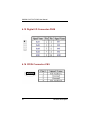
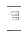
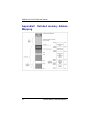
1
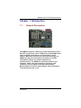
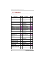
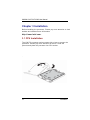
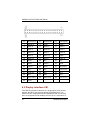
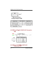
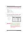
IMB200 Intel ® PentiumD/Pentium4/Celeron D Industrial ATX Motherboard User’s Manual Disclaimers The information in this manual has been carefully checked and is believed to be accurate. AXIOMTEK Co., Ltd. assumes no responsibility for any infringements of patents or other rights of third parties which may result from its use. AXIOMTEK assumes no responsibility for any inaccuracies that may be contained in this document. AXIOMTEK makes no commitment to update or to keep current the information contained in this manual. AXIOMTEK reserves the right to make improvements to this document and/or product at any time and without notice. No part of this document may be reproduced, stored in a retrieval system, or transmitted, in any form or by any means, electronic, mechanical, photocopying, recording, or otherwise, without the prior written permission of AXIOMTEK Co., Ltd. ©Copyright 2007 by AXIOMTEK Co., Ltd. All rights reserved. April 2007, Version A2 ii ESD Precautions Integrated circuits on computer boards are sensitive to static electricity. To avoid damaging chips from electrostatic discharge, observe the following precautions: Do not remove boards or integrated circuits from their anti-static packaging until you are ready to install them. Before handling a board or integrated circuit, touch an unpainted portion of the system unit chassis for a few seconds. This helps to discharge any static electricity on your body. Wear a wrist-grounding strap, available from most electronic component stores, when handling boards and components. Trademarks Acknowledgments AXIOMTEK is a trademark of AXIOMTEK Co., Ltd. IBM is a registered trademark of International Business Machines Corporation. MS-DOS, and Windows 2000 are trademarks of Microsoft Corporation. Award is a trademark of Award Software, Inc. IBM, PC/AT, PS/2, VGA are trademarks of International Business Machines Corporation. Intel Pentium D, Pentium4, Celeron D is trademarks of Intel Corporation. Other brand names and trademarks are the properties and registered brands of their respective owners. iii Table of Contents Disclaimers .................................................................... ii ESD Precautions ........................................................... iii Chapter 1 Introduction........................................................ 1 1.1 General Description ............................................. 1 1.2 Specifications ...................................................... 2 1.3 Utilities Supported................................................ 3 1.4 Ordering information ............................................ 3 1.4 Board Dimensions ................................................ 5 Chapter 2 Jumpers and Connectors .................................... 6 2.1 Board Layout ....................................................... 6 2.2 Jumper Settings ................................................... 7 2.2.1 Watchdog Tigger Mode: JP2……………………….. 7 2.2.2 Clear CMOS Setting: JP7…………………………… 8 2.2.3 CF Master/Slave Setting: JP8………………………. 8 2.2.4 CF Power Setting: JP9………………………………. 9 2.3 Connectors ........................................................ 10 Chapter 3 Installation ........................................................ 12 3.1 CPU Installation .................................................... 12 3.2 Installing ATX Power Supply…………………………..19 3.3 Installing the Memory ............................................. 19 Chapter 4 Hardware Description ....................................... 21 4.2 Enhane IDE1/IDE2 connecotor-IDE1 and IDE2 ........ 21 4.3 Display interface-CN1............................................. 22 4.4 Floppy Disck Connector-FDD .................................. 23 4.5 Parallel Port Connector .......................................... 24 4.6 COM1 Port Connector-CN2..................................... 25 4.7 COM2/3/4 Port Connector-CN25/CN27/CN33 support RS232 ......................................................................... 25 4.8 USB and Giagbit LAN RJ-45 Connector-CN6 ........... 26 4.9 USB and 10/100Mb LAN RJ-45 Connector-CN7....... 26 4.10 USB Connector by pin header-CN30 ..................... 27 4.11 Audio Jack (Line-in/Line-Out/MIC)-CN3................. 28 4.12 ATX12V CPU Power Connector: CN14 .................. 28 iv 4.13 4.14 4.15 4.16 4.17 Serial ATA Connectors-CN28/CN29 ...................... 29 PS/2 Keyboard/Mouse connector-CN4 .................. 29 Digital I/O Connector-CN38 .................................. 30 CD/IN Connector-CN9 .......................................... 30 CPU/System FAN Connector-CN23/CN24 ............. 31 Chapter 5 Installing VGA driver ......................................... 32 5.1 Introduction........................................................ 32 5.2 Driver Disks’ Contents........................................ 32 5.3 Windows 2000 VGA Driver Installation ................ 32 5.4 Windows XP VGA Driver Installation ................... 34 Chapter 6 Installing LAN Driver........................................ 35 6.1 Introduction........................................................ 35 6.3 Drivers Supported .............................................. 35 Chapter 7 Award BIOS Utility ........................................... 36 7.2 BIOS Setup ........................................................ 36 7.3 Standard CMOS Setup ....................................... 38 7.4 Advanced BIOS Features ................................... 41 7.4.1 CPU Feature…………………………………………. 41 7.4.2 Hard Disk Boot Priority……………………………… 43 7.5 Advanced Chipset Features................................ 46 7.6 Integrated Peripherals ........................................ 50 7.6.1 On-Chip IDE Device………………………………… 50 7.6.2 Onboard Device……………………………………. 52 7.6.3 Super IO Device……………………………………. 54 7.7 Power Management Setup.................................. 57 7.8 PNP/PCI Configuration ....................................... 60 7.9 PC Health Status ............................................... 62 7.10 Frequency/Voltage Control ................................. 63 7.11 Load Fail-Safe Default .......................................... 64 7.12 Load Optimized Default ........................................ 64 7.13 Supervisor/User Password Setting ........................ 64 7.14 Exit Setting........................................................... 66 A p p e n d i x A Watchdog Timer .................................... 68 A p p e n d i x B PCI IRQ Routing ..................................... 69 PICMG PCI IRQ Routing................................ 69 On Board Device IRQ Routing ....................... 69 v AppendixC Detailed memory Addess Mapping ................ 70 AppendixD I/O Shield........................................................ 71 vi IMB200 LGA775 ATX MB User Manual Chapter 1 Introduction 1.1 General Description The IMB200 supports LGA775-pin Intel® Pentium® D (Intel Dual-Core) processor up to 3.6GHz with a 533/800MHz front side bus (FSB), and features an Intel® 865G + ICH*5 chipset. With Intel dual-core processing technology, the IMB200 provides the excellent performance to handle multitasking and to run multiple applications simultaneously. The IMB200 is specially suited for the solutions which need more effective computing and reliability, such as Digital Video Recorder/Gamine Machine/Point of Service System/Video Server/Intelligent Transmit System and so on. Introduction 1 IMB200 LGA775 ATX MB User Manual 1.2 Specifications ¾ Processor: Intel ® Pentium D/Pentium4/Celeron ¾ North Bridge: Intel ® 82865G ¾ South Bridge: Intel ® 82801EB(ICH5) ¾ CPU Socket: LGA775 ¾ FSB: 533/800 Mhz ¾ L2 Cache: Integrated in CPU(Depend on CPU) ¾ BIOS: Phoenix Award BIOS Rev.6.00 ¾ System Memory: Support Dual Channel DDR 266/333/400 memory and the maximum capacity up to 4GB. CPU FSB DDR Type DDR Frequency 800MHz PC3200/PC2700/PC2100 400/333*/266MHz 533MHz PC2700/PC2100 333/266MHz *Because limited of chipset, when using FSB800Mhz CPU, PC2700 DDR (333 MHz) only supports 320 MHz. ¾ IDE Interface: Two IDE connector and up to four devices, Ultra DMA 100 supported ¾ FDD Interface: Supports up to 2 drives ¾ Serial Ports: RS232 Portx4 ¾ Parallel Ports: One parallel port with ECP/EPP/SPP supported ¾ VGA Controller: ¾ Chipset Integrated VGA Controller and Supports up to 2048x1536 at 75 Hz resolution on non-interlaced CRT monitors ¾ Ethernet: Intel82547GI/Intel82562ET ¾ SATA: Two Channel and support the maximum data transfer rate could up to 150MB/s 2 Introduction ¾ IMB200 LGA775 ATX MB User Manual CF Socket: Support CF Type II Socket ¾ USB Interface: 4 USB ports; USB Spec. Rev. 2.0 compliant. ¾ Hardware Monitoring: Winbond W83627HG-AW detection of CPU temperature, System temperature, Power failure and Fan speed. ¾ Watchdog Timer: Software programmable time interval and hardware reset Only (1~255 seconds) ¾ Dimensions:304.8mmx243.8mm ¾ PCB 4 Layer ¾ Form factor :ATX Former ¾ Environmental: Operating temperature 0 degrees to 60 degrees(Depends on CPU) CPU Relative Humidity 95% NOTE: Specifications are subject to change without notice. 1.3 Utilities Supported z z z z 1.4 Intel ® 865G Utility and Drivers Ethernet Utility and Drivers VGA Drivers Audio Driver Ordering information Model number Description IMB200VGE Intel547GI/Intel82562ET LAN IMB200VG Intel547GI Introduction 3 IMB200 LGA775 ATX MB User Manual 4 Introduction IMB200 LGA775 ATX MB User Manual 1.4 Board Dimensions Introduction 5 IMB200 LGA775 ATX MB User Manual Chapter 2 Jumpers and Connectors 2.1 6 Board Layout Jumpers and Connectors IMB200 LGA775 ATX MB User Manual 2.2 Jumper Settings Followed as below detailed description for Jumper setting and installed the IMB200 for your application Jumper Jumper Setting Default Setting JP2 Watchdog Trigger Mode : Disable JP7 CMOS Clear Jumper : Normal Mode JP8 Compact Flash Master/Slave : Master JP9 Compact Flash Power Select : 3.3V OPEN Short 1-2 for NMI Short 2-3 for Reset Short 1-2 for Normal Short 2-3 for Clear Short for Master Open for Slave Short 1-2 for 3.3V Short 2-3 for 5V 2.2.1 Watchdog Trigger Mode: JP2 Jumpers and Connectors Options Settings NMI 1-2 RESET 2-3 Disabled Open (Default) 7 IMB200 LGA775 ATX MB User Manual 2.2.2 Clear CMOS Setting: JP7 Options Settings Normal 1-2(Default) Clear CMOS 2-3 2.2.3 CF Master/Slave Setting: JP8 8 Options Settings Master Short(Default) Slave Open Jumpers and Connectors IMB200 LGA775 ATX MB User Manual 2.2.4 CF Power Setting: JP9 Jumpers and Connectors Options Settings 3.3V 1-2(Default) 5V 2-3 9 IMB200 LGA775 ATX MB User Manual 2.3 Connectors The following table lists the function of each connector on the IMB200. Connectors General Output Connector Printer Port Connector Label Connectors Label CN37 IDE1 System BIOS U41 CRT Connector Keyboard/Mouse Connector Gigabit Ethernet Connector Fast Ethernet Connector CN1 CN4 Primary IDE Connector Secondary IDE Connector Compact Flash Connector S-ATA Port 1 Connector S-ATA Port 2 Connector FDD Connector IrDA Connector CPU FAN Connector SYSTEM FAN1 Connector SYSTEM FAN2 Connector Internal Buzzer Internal Battery CN6 Audio Jack CN3 CN7 AUX Input Connector CD Input Connector CN8 CN5 COM1 CN2 COM2 CN33 COM3 CN25 COM4 USB Port 1, 2 Connector USB Port 3, 4 Connector USB Port 5, 6 Connector CN27 CN6 CN7 CN30 Gigabit Ethernet External Speed LED Fast Ethernet External Speed LED Gigabit Ethernet External Link/ACT LED CN13 Fast Ethernet External Link/ACT LED ATX12V CPU Power Connector 10 IDE2 CN26 SATA 1 SATA 2 FDD CN12 CN23 CN36 CN24 BU1 BAT1 CN9 CN17 Speaker Output Connector CN10 CN16 184-Pin DDR Memory Channel-A DIMM 1/2 CN15 184-Pin DDR Memory Channel-B DIMM 3/4 CN14 ISA Slot ISA1/ 2 Jumpers and Connectors IMB200 LGA775 ATX MB User Manual Connectors ATX Power Connector LGA775 CPU Socket DIO Connector Jumpers and Connectors Label Connectors CN31 PCI Slot U22 AGP Slot Label PCI1~ 5 AGP8 X1 CN38 11 IMB200 LGA775 ATX MB User Manual Chapter 3 Installation Before installing the processor, Please pay more attention on Intel website and obtained more information http://www.intel.com. 3.1 CPU Installation The LGA775 processor socket comes with a lever to protect the processor. Please pay more attention as below. Follow the pictures and place the processor into CPU socket. . 12 Installation IMB200 LGA775 ATX MB User Manual . Installation 13 IMB200 LGA775 ATX MB User Manual 14 Installation IMB200 LGA775 ATX MB User Manual Installation 15 IMB200 LGA775 ATX MB User Manual 16 Installation IMB200 LGA775 ATX MB User Manual Installation 17 IMB200 LGA775 ATX MB User Manual 18 Installation IMB200 LGA775 ATX MB User Manual 3.2 Installing ATX Power Supply System power was provided for the IMB200 Industrial motherboard by CN31 3.3 Installing the Memory The IMB200 support Dual Channel DDR 266/333/400 memory and support the maximum memory capacity could up to 4GB. If you want to know what is difference between DDR and DDR2.See below picture PS: IMB200 only support Un-Buffered DIMM and could not support ECC/Registered DIMM Installation 19 IMB200 LGA775 ATX MB User Manual 20 Installation IMB200 LGA775 ATX MB User Manual Chapter 4 Hardware Description 4.1 General Output Connector: CN37 Power LED Pins 1, 3, 5, 7 connect the system power LED indicator to its respective switch on the case. Pin 1 is +, and pin 5 is assigned as -.Pin 7 is defined as NC External Speaker and Internal Buzzer Connector Pins 2, 4, 6, 8 connect to the case-mounted speaker unit or internal buzzer. Hardware Reset Pins 11 & 12 were designed for Hardware Reset. HDD Activity LED This connector extends to the hard drive activity LED on the control panel. This LED will flash when the HDD is being accessed. Pins 13 & 14 connect the hard disk drive and the front panel HDD LED. Power Button This 2-pin connector was designed at Pin9/10 4.2 Enhance IDE1/IDE2 connecotor-IDE1 and IDE2 The IMB200 provided two IDE Port and support the maximum IDE devices could up to four IDE devices. Hardware Description 21 IMB200 LGA775 ATX MB User Manual Pin Description Pin Description Pin Description 1 Reset # 2 GND 3 Data 7 4 Data 8 5 Data 6 6 Data 9 7 Data 5 8 Data 10 9 Data 4 10 Data 11 11 Data 3 12 Data 12 13 Data 2 14 Data 13 15 Data 1 16 Data 14 17 Data 0 18 Data 16 19 GND 20 N/C 21 N/C 22 GND 23 IOW # 24 GND 25 IOR # 26 GND 27 IOCHRDY 28 N/C 29 N/C 30 GND-Default 31 Interrupt 32 N/C 33 SA1 34 N/C 35 SA0 36 SA2 37 HDC CS0 # 38 HDC CSI # 39 HDD Active # 40 GND . 4.3 Display interface-CN1 The GMCH provides interfaces to a progressive scan analog monitor and DVO can drive a variety of DVOdevices• The GMCH has an integrated 350 MHz RAMDAC that can directly drive a progressive scan analog monitor up to a resolution of 22 Hardware Description IMB200 LGA775 ATX MB User Manual 2048x1536 at 75 Hz. Pin Signal Pin Signal Pin Signal 1 Red 2 Green 3 Blue 4 N/A 5 GND 6 AGND 7 AGND 8 AGND 9 +5V 10 GND 11 N/A 12 DDC DAT 13 Horizontal Sync 14 Vertical Sync 15 DDC CLK 4.4 Floppy Disk Connector-FDD The IMB200 provides a 34-pin header type connector supporting up to two floppy drives. The floppy drives may be any one of the following types: 5.25" 360KB/1.2MB and 3.5" 720KB/1.44MB/2.88MB. Pin 1 Description GND Pin 2 Description Reduce write Pin Description 3 GND Current 4 N/C 5 GND 6 N/C 7 GND 8 Index # 9 GND 10 Motor enable A # 11 GND 12 Drive Select B # 13 GND 14 Drive select A # 15 GND Hardware Description 23 IMB200 LGA775 ATX MB User Manual 16 Motor enable B # 17 GND 18 Direction # 19 GND 20 STEP # 21 GND 22 Write data # 23 GND 24 Write gate # 25 GND 26 Track # 27 GND 28 Write protect # 29 GND 30 Read data # 31 GND 32 Side 1 select # 33 GND 34 Disk change # . 4.5 Parallel Port Connector z Standard mode: IBM PC/XT, PC/AT and PS/2 TM compatible with bi-directional parallel port z Enhanced mode: Enhance parallel port (EPP) compatible with EPP 1.7 and EPP 1.9 (IEEE 1284 compliant) z High speed mode: Microsoft and Hewlett Packard extended capabilities port (ECP) IEEE 1284 compliant The address select of the onboard parallel port in LPT1 (3BCH) or disabled is done by BIOS CMOS setup. Pin Description Pin Description 1 Strobe # 14 Auto Form Feed # 2 Data 0 15 Error # 3 Data 1 16 Initialize # 4 Data 2 17 Printer Select In # 24 Hardware Description IMB200 LGA775 ATX MB User Manual 5 Data 3 18 GND 6 Data 4 19 GND 7 Data 5 20 GND 8 Data 6 21 GND 9 Data 7 22 GND 10 Acknowledge # 23 GND 11 Busy 24 GND 12 Paper Empty # 25 GND 13 Printer Select 26 4.6 COM1 Port Connector-CN2 4.7 COM2/3/4 Port ConnectorCN25/CN27/CN33 support RS232 Hardware Description 25 IMB200 LGA775 ATX MB User Manual 4.8 USB and Gigabit LAN RJ-45 ConnectorCN6 4.9 USB and 10/100Mb LAN RJ-45 Connector-CN7 26 Hardware Description IMB200 LGA775 ATX MB User Manual 4 .10 USB Connector by pin header-CN30 USB USB U SB USB G ND P0+ P0- Power 1 10 2 AG ND USB U SB USB USB G ND P1+ P1+ Power Hardware Description 27 IMB200 LGA775 ATX MB User Manual 4.11 Audio Jack (Line-in/Line-Out/MIC)-CN3 4.12 ATX12V CPU Power Connector: CN14 This connector connected to an ATX12V power supply and used for CPU Core Voltage. Important Note: Make sure your ATX12V power supply can provide 16A on the +12V lead and at least 1A on the +5V standby lead (+5VSB). The minimum recommended wattage is 250W or 300W for a fully configured system. The system may become unstable and may experience difficulty powering up if the power supply is inadequate. 28 Hardware Description IMB200 LGA775 ATX MB User Manual 4.13 Serial ATA Connectors-CN28/CN29 4.14 PS/2 Keyboard/Mouse connector-CN4 Hardware Description 29 IMB200 LGA775 ATX MB User Manual 4.15 Digital I/O Connector-CN38 4.16 CD/IN Connector-CN9 30 Hardware Description IMB200 LGA775 ATX MB User Manual 4.17 CPU/System FAN ConnectorCN23/CN24 Hardware Description 31 IMB200 LGA775 ATX MB User Manual Chapter 5 Installing VGA driver 5.1 Introduction The GMCH provides interfaces to a progressive scan analog monitor. The GMCH has an integrated 350 MHz RAMDAC that can directly drive a progressive scan analog monitor up to a resolution of 2048x1536 at 75 Hz. 5.2 Driver Disks’ Contents The driver diskettes that come with the IMB200 Series package contain the following installation programs: Win2000 driver WinXP driver 5.3 Windows 2000 VGA Driver Installation To install or upgrade the DirectX driver Microsoft DirectX 8.0a must be installed prior to installing the video driver support on the IMB200 Series. If you’ve installed a retail version of Windows 2000 you’ll need to install Microsoft DirectX 8.0a. This file can be downloading from http://www.microsoft.com/windows/directx/default.asp To install video support If you have installed retail Windows you need to install the video driver. The driver is contained in the \IMB200\Drivers\VGA subdirectory on the drivers CD. 32 Installing VGA Driver IMB200 LGA775 ATX MB User Manual To install or upgrade the Intel 865G video driver: 1. Run SETUP.EXE from the driver directory on your drivers CD 2. Follow the onscreen directions to complete installation. 3. There may be messages about the driver not having a digital signature, select Yes to all these message boxes. 4. Upon successful completion you will be asked to reboot your computer, choose “Yes, I want to restart my computer now” if you have no other drivers to install. Otherwise, choose “No, I will restart my computer later” and continue to next step. Installing VGA Driver 33 IMB200 LGA775 ATX MB User Manual 5.4 Windows XP VGA Driver Installation To install video support If you have installed retail Windows you need to install the video driver. The driver is contained in the \IMB200\Drivers\VGA subdirectory on the drivers CD. To install or upgrade the video driver: 1. Run SETUP.EXE from the video driver directory. 2. Follow the onscreen directions to complete the installation. 3. At the end you will be asked to reboot the PC. Choose YES and press FINISH to exit the video driver installation. 34 Installing VGA Driver IMB200 LGA775 ATX MB User Manual Chapter 6 Installing LAN Driver 6.1 Introduction The IMB200 was built-in high performance Plug and Play Ethernet interface which is fully compliant with the IEEE 802.3 standard, and consisting of the RJ-45 connector 6.2 Features z 10/100/1000BASE-T Triple-speed MAC z PCI host interface z Standards compliant WOL 6.3 Drivers Supported The onboard LAN Chip for IMB200 Ethernet interface allows great flexibility to work with all major networking operating systems including Windows 2000, XP, Linux 2.2, 2.4, Netware, Solaris x86 and UNIX. NOTE: Before installing LAN driver, please followed the detailed installation procedure from the Product Information CD-ROM and be sure to make installation and backup copies of the driver files. Installing LAN Driver 35 IMB200 LGA775 ATX MB User Manual Chapter 7 Award BIOS Utility Please pay more time and check all of detailed information for BIOS settings when you want to used the IMB200 7.1 BIOS Introduction The Award BIOS (Basic Input/Output System) installed in your computer system’s ROM supports Intel Celeron processors in a standard IBM-AT compatible I/O system. The BIOS provides critical low-level support for standard devices such as disk drives, serial and parallel ports. It also adds virus and password protection as well as special support for detailed fine-tuning of the chipset controlling the entire system. 7.2 BIOS Setup The Award BIOS provides a Setup utility program for specifying the system configurations and settings. The BIOS ROM of the system stores the Setup utility. When you turn ON the computer, the Award BIOS is immediately activated. Pressing the <Del> key immediately allows you to enter the Setup utility. If you are a little bit late pressing the <Del> key, POST (Power on Self Test) will continue with its test routines, thus preventing you from invoking the Setup. If you still wish to enter Setup, restart the system by pressing the ”Reset” button or simultaneously pressing the <Ctrl>, <Alt> and <Delete> keys. You can also restart by turning the system OFF and back ON again. The following message will appear on the screen: Press <DEL> to Enter Setup In general, you press the arrow keys to highlight items, <Enter> to select, the <PgUp> and <PgDn> keys to change entries, <F1> for help and <Esc> to quit. When you enter the Setup utility, the Main Menu screen will appear on the screen. The Main Menu allows you to select 36 Award BIOS Utility IMB200 LGA775 ATX MB User Manual from various setup functions and exit choices. The section below the setup items of the Main Menu displays the control keys for this menu. Another section located at the bottom of the Main Menu, just below the control keys section, displays information on the currently highlighted item in the list. NOTE: If you find that your computer cannot boot after making and saving system changes with Setup, the Award BIOS, via its built-in override feature, resets your system to the CMOS default settings. We strongly recommend that you avoid making any changes to the chipset defaults. These defaults have been carefully chosen by both Award and your system manufacturer to provide the absolute maximum performance and reliability. Award Bios Utility 37 IMB200 LGA775 ATX MB User Manual 7.3 Standard CMOS Setup “Standard CMOS Setup” allows you to record some basic hardware configurations in your computer system and set the system clock and error handling. If the motherboard is already installed in a working system, you will not need to select this option. You will need to run the Standard CMOS option, however, if you change your system hardware configurations, the onboard battery fails, or the configuration stored in the CMOS memory was lost or damaged. At the bottom of the menu are the control keys for use on this menu. If you need any help in each item field, you can press the <F1> key. It will display the relevant information to help you. The memory display at the lower right-hand side of the menu is read-only. It will adjust automatically according to the memory changed. The following pages describe each item of this menu. 38 Award BIOS Utility IMB200 LGA775 ATX MB User Manual z Date The date format is <day>, <month>, <date>, <year>. Press <F3> to show the calendar. day date month year z The day of week, from Sun to Sat, determined by the BIOS, is read only The date, from 1 to 31 (or the maximum allowed in the month), can key in the numerical / function key The month, Jan through Dec. The year, depends on the year of BIOS Time The time format is <hour> <minute> <second> accepting either functions key or numerical key. The time is calculated based on the 24-hour military-time clock. For example, 1 p.m. is 13:00:00. z IDE Channel 0 Master/IDE Channel 0 Slave/IDE Channel 1 Master/IDE Channel 1 Slave The categories identify the types of one channel that have been installed in the computer. There are 45 predefined types and 2 users definable types are for Enhanced IDE BIOS. Type 1 to Type 45 is predefined. Type User is user-definable. Press <PgUp>/<+> or <PgDn>/<−> to select a numbered hard disk type or type the number and press <Enter>. Note that the specifications of your drive must match with the drive table. The hard disk will not work properly if you enter improper information within this category. If your hard disk drive type does not match or is not listed, you can use Type User to define your own drive type manually. If you select Type User, related information is asked to be entered to the following items. Enter the information directly from the keyboard and press <Enter>. This information should be provided in the documentation from your hard disk vendor or the system manufacturer. If the controller of HDD interface is ESDI, select “Type 1”. If the controller of HDD interface is SCSI, select “None”. If the controller of HDD interface is CD-ROM, select “None”. CYLS. number of cylinders LANDZONE landing zone HEADS number of heads SECTORS number of sectors PRECOMP write precom MODE HDD access mode If there is no hard disk drive installed, select NONE and press <Enter>. Award Bios Utility 39 IMB200 LGA775 ATX MB User Manual z Drive A type/Drive B type The category identifies the types of floppy disk drive A or drive B installed in the computer. z None No floppy drive installed 360K, 5.25 in 5.25 inch PC-type standard drive; 360Kb capacity 1.2M, 5.25 in 5.25 inch AT-type high-density drive; 1.2MB capacity 720K, 3.5 in 3.5 inch double-sided drive; 720Kb capacity 1.44M, 3.5 in 3.5 inch double-sided drive; 1.44MB capacity 2.88M, 3.5 in 3.5 inch double-sided drive; 2.88MB capacity Halt On This field determines whether the system will halt if an error is detected during power up. No errors All errors All, But Keyboard All, But Diskette All, But Disk/Key 40 The system boot will halt on any error detected. Whenever the BIOS detects a non-fatal error, the system will stop and you will be prompted.(Default) The system boot will not stop for a keyboard error; it will stop for all other errors. The system boot will not stop for a disk error; it will stop for all other errors. The system boot will not stop for a keyboard or disk error; it will stop for all other errors. Award BIOS Utility IMB200 LGA775 ATX MB User Manual 7.4 Advanced BIOS Features This section allows you to configure and improve your system and allows you to set up some system features according to your preference. 7.4.1 CPU Feature Clicks the cursor to this field and press <Enter>. The following screen will be appeared. The setting on the screen is for reference only. Your version Award Bios Utility 41 IMB200 LGA775 ATX MB User Manual may not be identical to this one. z Delay prior to Thermal This filed is used to select the time that would force the CPU to a 50% duty cycle when it exceeds us maximum operating temperature therefore protecting the CPU and the system board From overheating to ensure a safe computing environment. z Thermal Management Thermal Monitor 1 On-die throttling Thermal Monitor 2 Ratio and VID transition z Limited CUPID MaxVal The CPUID instruction if some newer CPUs will return a value greater than 3. The default is disabled because this problem does not exist in the Windows series operating systems. If you are using an operating system other than Windows, this problem May occur. To avoid this problem, enable this field to limit the return value to 3 or lesser than 3. z C1E Function The Pentium 4 5xxJ version already features a power management function to reach the same level with the Enhanced Halt State (C1E). With the C1E, it was either x14 or the maximum coefficient without intermediate levels. So at 0% of use the coefficient was x14 / 1.2v, and for a use of 5%, the coefficient and electrical tension were set to the maximum z Execute Disable Bit Execute Disable Bit is a hardware-based security feature that can reduce exposure to viruses and malicious-code attacks and prevent harmful software from executing and propagating on the server or network. Help protect your customers' business assets and reduce the need for costly virus-related repairs z Virtualization Technology Intel® Virtualization Technology requires a computer system with a processor, chipset, BIOS, virtual machine monitor (VMM) and for some uses, certain platform software enabled for it. Functionality, performance or other benefit will vary depending on hardware and software configurations 42 Award BIOS Utility IMB200 LGA775 ATX MB User Manual 7.4.2 Hard Disk Boot Priority This field is used to select the boot sequence of the hard drives. Move the cursor to this field then press <Enter>. Use the Up or Down arrow keys to select a device then press<+> to move it up or <-> to move it down the list. z Virus Warning This item protects the boot sector and partition table of your hard disk against accidental modifications. If an attempt is made, the BIOS will halt the system and display a warning message. If this occurs, you can either allow the operation to continue or run an anti-virus program to locate and remove the problem. NOTE: Many disk diagnostic programs, which attempt to access the boot sector table, can cause the virus warning. If you will run such a program, disable the Virus Warning feature. z Quick Power On Self Test E nabling this setting will cause the BIOS power-on self test routine to skip some of its tests during boot up. One of the key things this setting usually does when enabled is cause the POST to skip checking all of extended memory for errors. Award Bios Utility 43 IMB200 LGA775 ATX MB User Manual Most people enable this setting to speed up the boot process, but you should realize that you do increase the chance of the POST missing an error if you use this. Fortunately (or unfortunately) the POST memory test is virtually useless to detect transient memory errors (as opposed to hard errors that you would discover the first time you powered up the machine with the new memory in it), so once your system is running and stable, you can in most cases enable this setting safely. It's still safest to leave it disabled, which is what I recommend unless you have truly monstrous amounts of RAM. After all, how often do you boot the system during normal use. z First/Second/Third Boot Device These items allow the selection of the 1 st , 2 nd , and 3 rd devices that the system will search for during its boot-up sequence. The wide range of selection includes Floppy, LS120, ZIP100, HDD0~3, SCSI, and CDROM. z Boot Other Device This item allows the user to enable/disable the boot device not listed on the First/Second/Third boot devices option above. The default setting is enabled. z Swap Floppy Drive This allows you to determine whether to enable Swap Floppy Drive or not. When enabled, the BIOS swap floppy drive assignments so that Drive A becomes Drive B and Drive B become Drive A. By default, this field is set to Disabled. z Boot Up Floppy Seek During POST, BIOS will determine the floppy disk drive type, 40 or 80 tracks, installed in the system. 360Kb type is 40 tracks while 720Kb, 1.2MB and 1.44MB are all 80 tracks. The default value is “Enabled”. 44 Enabled BIOS searches for floppy disk drive to determine if it is 40 or 80 tracks. Note that BIOS can not tell from 720K, 1.2M or 1.44M drives type as they are all 80 tracks. Disabled BIOS will not search for the type of floppy disk drive by track number. There will be no warning message displayed if the drive installed is 360K. Award BIOS Utility IMB200 LGA775 ATX MB User Manual z Boot Up NumLock Status This option enables and disables the numberlock function of the keypad. The default value is “On”. On Off z Keypad functions confine with numbers Keypad functions convert to special functions (i.e., left/right arrow keys) APIC Mode This item can enable or disable the APIC (Advanced Programmable Interrupt. Controller). Due to compliance to PC2001 design guide, the system is able to run. In APIC mode. Enabling APIC mode will expand available IRQs Controller. Award Bios Utility 45 IMB200 LGA775 ATX MB User Manual 7.5 Advanced Chipset Features Since the features in this section are related to the chipset on the CPU board and are completely optimized, you are not recommended to change the default settings in this setup table unless you are well oriented with the chipset features. z DARM Timing Selectable This field is used to select the timing of the DRAM. By SPD The EEPROM on a DIMM has SPD (Serial Presence Detect) data structure that stores information about the module such as the memory type, memory size, memory speed etc. When this option is selected the system will run according to the information in the EEPROM. This option is the default setting because it provides the most stable condition for the system. The “CAS Latency Time “ To “System Memory Frequency “field will show the default settings by SPD. 46 Award BIOS Utility IMB200 LGA775 ATX MB User Manual Manual z If you want better performance for your system other than the one “ by SPD “ select “ Manual “ then select the best option in the “ CAS Latency Time “ To “System Memory Frequency “fields. CAS Latency Time This refers to the Column Address Strobe delay time. Lower is better! However, in a P4 system, lowering this setting only improves performance minimally, so it might be better to increase this setting to gain stability or a higher over clock. z Active Precharge Delay This refers to the Active to Precharge delay time. Lower is better! However, same as above, lowering this setting only improves performance minimally, so it might be better to increase this setting to gain stability or a higher over clock. z DRAM RAS# to CAS# Delay This refers to the Row Address Strobe to Column Address Strobe delay time. Lower is better! This is the most crucial setting in a P4 system! Lowering this setting improves performance quite noticeably, so you might want to sacrifice some clock speed to lower this timing. z DRAM RAS# Precharge This refers to the Row Address Strobe to Column Address Strobe delay time. Lower is better! This is the 2nd most crucial setting in a P4 system! Lowering this setting improves performance quite noticeably, so you might want to sacrifice some clock speed to lower this timing z System Memory Frequency The Intel 865G Support Intel DDR 266/333/400.This setting could help you and setup the DRAM clock for DDR memory module. The default setting was Auto z System BIOS Cacheable When this field is enabled, accesses to the system BIOS ROM Address at F0000H-FFFFFH are cached, provide that the cache controller is enabled. z Video BIOS Cacheable As with caching the system BIOS, enabling the Video BIOS Award Bios Utility 47 IMB200 LGA775 ATX MB User Manual cache will allow access to video BIOS addressed at C0000H To be cached if the cache controller is also enabled. The larger the range of the Cache RAM, the faster the video performance. z Memory Hole At 15M-16M You can reserve this area of system memory for ISA adapter ROM. When this area is reserved, it can’t be Cached. The user information of peripherals that need To use this area of system memory usually discusses their Memory requirements. z AGP Aperture Size (MB) This field determines the effective size of the Graphic Aperture used for a particular GMCH configuration. It can be updated by the GMCH-specific BIOS configuration sequence before the PCI standard bus enumeration sequence takes place. If it is not updated then a default value will select an aperture of maximum size. z Init Display First This BIOS feature allows you to select whether to boot the system using the AGP graphics card or the PCI graphics card. This is particularly important if you have AGP and PCI graphics cards but only one monitor. If you are only using a single graphics card, then the BIOS will detect it as such and boot it up, irrespective of what you set the feature to. However, there may be a slight reduction in the time taken to detect and initialize the card if you select the proper setting for this BIOS feature. For example, if you only use an AGP graphics card, then setting Init Display First to AGP may speed up your system's bootingup process. Therefore, if you are only using a single graphics card, it is recommended that you set the Init Display First feature to the proper setting for your system (AGP for a single AGP card and PCI for a single PCI card). 48 Award BIOS Utility IMB200 LGA775 ATX MB User Manual But if you are using multiple graphics cards, it is up to you which card you want to use as your primary display card. It is recommended that you select the fastest graphics card as the primary display card. **On-Chip VGA Setting** z On-Chip VGA This item allows to Disabled or enabled onboard VGA z On-Board Frame Buffer Size This item allows adjusting the Frame Buffer Size Award Bios Utility 49 IMB200 LGA775 ATX MB User Manual 7.6 Integrated Peripherals This option sets your hard disk configuration, mode and port. 7.6.1 On-Chip IDE Device Move the cursor to this field and press <Enter>. The following screen will be appeared. 50 Award BIOS Utility IMB200 LGA775 ATX MB User Manual z On-Chip Primary PCI IDE This option could allow you to enable or disable the primary and secondary IDE controller, select Disabled if you want to add a Different hard drive controller. z IDE Primary Master PIO This option could allow you to set up Master IDE interface from PIO mode0 to PIO Mode 4 z IDE Primary Slave PIO This option could allow you to set up Slave IDE interface from PIO mode0 to PIO Mode 4 z IDE Primary Master UDMA This option could allow you to enabled or disabled onboard Ultra DMA mode on Primary Master z IDE Primary Slave UDMA This option could allow you to enabled or disabled onboard Ultra DMA mode on Primary Slave z On-Chip Secondary PCI IDE This option could allow you to enabled or disabled onboard Secondary PCI IDE controller z IDE Primary Master PIO Award Bios Utility 51 IMB200 LGA775 ATX MB User Manual This option could allow you to set up Master IDE interface from PIO mode0 to PIO Mode 4 z IDE Primary Slave PIO This option could allow you to set up Slave IDE interface from PIO mode 0 to PIO Mode 4 z IDE Primary Master UDMA This option could allow you to enabled or disabled onboard Ultra DMA mode on Primary Master z IDE Primary Slave UDMA This option could allow you to enabled or disabled onboard Ultra DMA mode on Primary Slave z On-Chip Serial ATA This option could allow you to enabled or disabled onboard SATA port function Combined Mode: This option allows you to use both IDE and SATA drive; allowing a maximum on 4 drives-1 IDE Master; 1 IDE Slave and 2 SATA. You must manually set the SATA and PATA drives mode in the “ PATA IDE Mode “ and “ SATA Port “ fields. Enhanced Mode: This option allows you to use both IDE And SATA drives; allowing a maximum of 6 drives – 1 IDE Master, 1 IDE Slave and 4 SATA. SATA Only This option automatically sets the SATA Drives to Primary Master Mode. Since the SATA drives are In Master mode, you can not set the IDE drive to Master Mode. 7.6.2 Onboard Device Move the cursor to this field and press <Enter>. The following Screen will be appeared. 52 Award BIOS Utility IMB200 LGA775 ATX MB User Manual z USB Controller This setting could help you enabled or Disabled Onboard USB controller z USB 2.0 Controller Select enabled if your system contains a Universal Serial Bus V2.0 (USB2.0) controller and you have USB2.0 peripherals. The choice: Enabled, Disabled. z USB Keyboard Support Select enabled if your system contains a Universal Serial Bus (USB) controller and you have a USB keyboard. z AC97 Audio This option could helps to disable or enabled onboard Audio function The choice: Enabled, Disabled. z Fast Ethernet Select Disabled could help to disable onboard Fast Ethernet controller z Gigabit Ethernet Award Bios Utility 53 IMB200 LGA775 ATX MB User Manual Select Disabled could help to disable onboard Gigabit Ethernet controller. 7.6.3 Super IO Device Move the cursor to this field and press < Enter >. The following Screen will be appeared. z z Onboard FDC Controller This option could allows you to disabled or enabled onboard FDC controller z Onboard Serial Port 1/Port 2 Select an address and corresponding interrupt for the first and second serial ports. The choice: 3F8/IRQ4, 2E8/IRQ3, 3E8/IRQ4, 2F8/IRQ3, Disabled, Auto. z UART Mode Select This item allows you to select UART mode. The choice: IrDA, ASKIR, Normal. z UR2 Duplex Mode This item allows you to select the IR half/full duplex function. 54 Award BIOS Utility IMB200 LGA775 ATX MB User Manual The choice: Half, Full. z UR2 Duplex Mode Half: Data is completely transmitted before receiving Data Full: Transmits and receives data simultaneously. z Onboard Parallel Port 378/IRQ7, 3BC/IRQ7, 278/IRQ5 Select the I/O address and IRQ for the onboard parallel port. Disabled: z Disables the onboard parallel port. Parallel Port Mode The options are SPP, EPP, ECP and ECP+EPP. These apply to a Standard specification and will depend on the type and speed of You device. Refer to your peripherals manual for the best option. SPP – Allows normal speed operation but in one direction only. ECP (Extended Capabilities Port) – Allow parallel port to operate in bidirectional mode and at a speed faster then the normal mode’s data transfer rate. EPP (Enhanced Parallel Port) – Allows bidirectional parallel port operation at maximum speed. z ECP mode Use DMA This is used to select a DMA channel of the parallel port. 7.6.4 Onboard UART 3/4 Use the onboard UART. In this mode you should use the Picasso SDK UART-functions. The. Data will be set to the RS232 a connector Award Bios Utility 55 IMB200 LGA775 ATX MB User Manual 7.6.5 Onboard UART 3/4 IRQ Use these BIOS setting could help to set up the IRQ for Onboard UART 7.6.6 Spread Spectrum Spread spectrum is a form of wireless communications in which the frequency of the transmitted signal is deliberately varied. These results in a much greater bandwidth than the signal would have if its frequency were not varied 56 Award BIOS Utility IMB200 LGA775 ATX MB User Manual 7.7 Power Management Setup The Power Management Setup allows you to save energy of your system effectively. It will shut down the hard disk and turn OFF video display after a period of inactivity. z ACPI Function This function should be enabled only in operating systems that support ACPI. Currently, only Windows 2000/ME/XP supports this function. If you want to use the Suspend to RAM function, Make sure this field is enabled then select “S3 (STR)” in the ACPI Suspend Type “field. z ACPI Suspend Type This field is used to select the type of Suspend mode. S1 (POS) S3 (STR) z Enables the Power on Suspend function. Enables the Suspend to RAM function. Power Management This field allows you select the type (or degree) of power saving By changing the length of idle time that elapses before the Suspend mode and HDD Power Down fields are activated. Award Bios Utility 57 IMB200 LGA775 ATX MB User Manual Min Saving: Minimum power saving time for the Suspend Mode (1 hour) and HDD Power Down (15 min.) Max Saving: Maximum power saving time for the Suspend Mode and HDD Power Down =1 min. User Define: Allows you to set the power saving time in The “Suspend Mode “and “HDD Power Down “fields. z Video Off Method This determines the manner in which the monitor is blanked. V/H SYNC + Blank: This selection will cause the system to turn off the vertical and horizontal synchronization ports and write blanks to the video buffer. Blank Screen: This option only writes blanks to Video buffer buffer. DPMS: Initializes display power management Signaling. Use this option if your video board supports it. z Video Off In Suspend This field is used to activate the video off feature when the system enters the Suspend mode. The options are Yes or No. z Suspend Type The options are Stop Grant and Power ON Suspend. z Suspend Mode This is selectable only when the Power Management field is set to User Define. When the system enters the Suspend mode according to the power saving time selected, the CPU and onboard peripherals will be shut off. z HDD Power Down When enabled and after the set time of system inactivity, the hard disk drive will be powered down while all other devices remain active. 58 Award BIOS Utility IMB200 LGA775 ATX MB User Manual z Soft-Off by PWR-BTTN Pressing the power button for more than 4 seconds forces the system to enter the Soft-Off state when the system has “hung.” The choice: Delay 4 Sec, Instant-Off. z Wake-Up By PCI card If this item is enable, it allows the system to resume from a software power down or power saving mode whenever there is an Incoming call to an installed fax/modem. This function needs to be supported by the relevant hardware and software. z Power On function Pressing this BIOS setting could helps you and power on the system by KB/Mouse PWN After PWR-Fail This item specifies whether your system will reboot after a power failure or interrupt occurs. Available settings are:. Off. Leaves the computer in the power off state. Award Bios Utility 59 IMB200 LGA775 ATX MB User Manual 7.8 PNP/PCI Configuration This section describes configuring the PCI bus system. PCI, or Personal Computer Interconnect, is a system which allows I/O devices to operate at speeds nearing the speed the CPU itself uses when communicating with its own special components. This section covers some very technical items and it is strongly recommended that only experienced users should make any changes to the default settings. z PNP OS Installed If all your operating systems support Plug & Play (PnP), select yes so that they can take over the management of device resources. If you are using a non-PnP-aware OS or not all of the operating systems you are using support PnP, select No to let the BIOS handle it instead. Note that Windows 2000 will work with ACPI even with PnP OS Installed set to Enabled. Just make sure you disable Advanced Power Management (APM). z 60 Reset Configuration Data Enabled: The BIOS will reset the Extended System Award BIOS Utility IMB200 LGA775 ATX MB User Manual Configuration Data (ESCD) once automatically. Disabled: The BIOS will not reset the configuration data. Resource controlled by The Award Plug and Play BIOS has the capacity to automatically configure all of the boot and Plug and Play compatible devices. However, this capability means absolutely nothing unless you are using a Plug and Play operating system such as Windows®98. The options available are Auto and Manual. PCI /VGA Palette Snoop The VGA "palette" is the set of colors that are in use by the video card when it is in 256-color mode. Since there are thousands of colors and only 256 can be used in that mode, a palette containing the current colors is used. Some special VGA cards, high-end hardware MPEG decoders etc. need to be able to look at the video card's VGA palette to determine what colors are currently in use. Enabling this feature turns on this palette "snoop Award Bios Utility 61 IMB200 LGA775 ATX MB User Manual 7.9 PC Health Status This option configures the PCI bus system. All PCI bus systems on the system use INT#, thus all installed PCI cards must be set to this value. z Current System1 Temperature. The current system power will be detected automatically. z Current CPU Temp The current system CPU temperature will be automatically detected by the system. z Current SYSTEM2 Temperature. Show you the current system2 temperature. z Current CPU FAN1 Speed These optional and read-only fields show the current speeds in RPM (revolution per minute) for the CPU fan and chassis fan as monitored by the hardware monitoring IC. RPM(Revolutions per Minute) z SYSTEM FAN1 Speed. Show you the current system fan1 temperature. 62 Award BIOS Utility IMB200 LGA775 ATX MB User Manual z SYSTEM FAN2 Speed. Show you the current system fan2 temperature z +3.3V/+5V/+12V/-12V/-5V/VBAT(V)/5VSB Show you the voltage of +3.3V/+5V/+12V/-12V/-5V. 7.10 Frequency/Voltage Control z CPU Clock Ratio This field is used to select the CPU’s frequency z Auto Detect DIMM/PCI Clk Leave this field in its default setting. Do not alter this setting unless advised by an engineer or technician. Award Bios Utility 63 IMB200 LGA775 ATX MB User Manual 7.11 Load Fail-Safe Default When you press <Enter> on this item you get a confirmation dialog box with a message similar to: Load Fail-Safe Defaults (Y/N)? N Pressing “Y” loads the default values that are factory settings for optimal performance system operations 7.12 Load Optimized Default When you press <Enter> on this item you get a confirmation dialog box with a message similar to: Load Optimized Defaults (Y/N)? N Pressing “Y” loads the default values that are factory settings for optimal performance system operations 7.13 Supervisor/User Password Setting You can set either supervisor or user password, or both of then. The differences between are: Set Supervisor Password: can enter and change the options of the setup menus. 64 Award BIOS Utility IMB200 LGA775 ATX MB User Manual Set User Password: just can only enter but do not have the right to change the options of the setup menus. When you select this function, the following message will appear at the center of the screen to assist you in creating a password. ENTER PASSWORD: Type the password, up to eight characters in length, and press <Enter>. The password typed now will clear any previously entered password from CMOS memory. You will be asked to confirm the password. Type the password again and press <Enter>. You may also press <Esc> to abort the selection and not enter a password. To disable a password, just press <Enter> when you are prompted to enter the password. A message will confirm the password will be disabled. Once the password is disabled, the system will boot and you can enter Setup freely. PASSWORD DISABLED. When a password has been enabled, you will be prompted to enter it every time you try to enter Setup. This prevents an unauthorized person from changing any part of your system configuration. Additionally, when a password is enabled, you can also require the BIOS to request a password every time your system is rebooted. This would prevent unauthorized use of your Award Bios Utility 65 IMB200 LGA775 ATX MB User Manual computer. You determine when the password is required within the BIOS Features Setup Menu and its Security option (see Section 3). If the Security option is set to “System”, the password will be required both at boot and at entry to Setup. If set to “Setup”, prompting only occurs when trying to enter Setup. 7.14 Exit Setting Save & Exit Setup Pressing <Enter> on this item asks for confirmation: Save to CMOS and EXIT (Y/N)? Y Pressing “Y” stores the selections made in the menus in CMOS – a special section of memory that stays on after you turn your system off. The next time you boot your computer, the BIOS configures your system according to the Setup selections stored in CMOS. After saving the values the system is restarted again. Quit Without Saving 66 Award BIOS Utility IMB200 LGA775 ATX MB User Manual Pressing <Enter> on this item asks for confirmation: Quit without saving (Y/N)? Y This allows you to exit Setup without storing in CMOS any change. The previous selections remain in effect. This exits the Setup utility and restarts your compute Award Bios Utility 67 IMB200 LGA775 ATX MB User Manual A p p e n d i x A Watchdog Timer Please follow the below WDT process for setup the WDT function. 68 Watchdog Timer IMB200 LGA775 ATX MB User Manual A p p e n d i x B PCI IRQ Routing PICMG PCI IRQ Routing Device ID Slot Int PCI Slot 1 31 0 CDAB PCI Slot 2 30 1 EFGH PCI Slot 3 29 2 FGHE PCI Slot 4 28 3 GHEF PCI Slot 5 27 5 HEFG On Board Device IRQ Routing Device ID Slot PCI-ISA Bridge 22 4 PCI IRQ Routing Int 69 IMB200 LGA775 ATX MB User Manual AppendixC Detailed memory Addess Mapping 70 Detailed Memory Address Mapping IMB200 LGA775 ATX MB User Manual AppendixD I/O Shield P/N was 728F2000100E I/O Shield 71