
1
S PD
WY6NN-13
APRS12 STATION LIST
1: WY6NN-13
17:14
2: N6ULN
16:32
3: KE6JML-7
16:04
4: KE6JMT-14
15:28
5: W6DJY-9
15:08
KJ6IHI
W6DJY-9
N
E
W
S
+135°
9.9mi
N 33°50.43
W118°13.72
0.11''
WEATHER
FIXED
TH-D72
TM‑D710
TM‑D710
83°F
180°
7mph
N6LUN
TM‑D710A/E/GA/GE
hPa
1011hPa
H
55%
MESSAGE
TO: W6DJY-9
I will leave home soon.
KE6JMT-14
Multi-communicator VHF/UHF FM Dual Bander
Getting More Acquainted with APRS and EchoLink
N
E
W
S
+045°
60.0mi
N33°21.45
W119°53.16
Copyrights for This Manual
•JVC KENWOOD Corporation shall own all copyrights and
intellectual properties for the product and the manuals, help texts
and relevant documents attached to the product or the optional
software.
•A user is required to obtain approval from JVC KENWOOD
Corporation, in writing, prior to redistributing this document on a
personal web page or via packet communication.
•A user is prohibited from assigning, renting, leasing or reselling the
document.
•JVC KENWOOD Corporation does not warrant that quality and
functions described in this manual comply with each user's
purpose of use and, unless specifically described in this manual,
JVC KENWOOD Corporation shall be free from any responsibility
for any defects and indemnities for any damages or losses.
Software Copyrights
•The title to and ownership of copyrights for software, including
but not limited to the firmware and optional software that may
be distributed individually, are reserved for JVC KENWOOD
Corporation. The firmware shall mean the software which can be
embedded in KENWOOD product memories for proper operation.
•Any modifying, reverse engineering, copying, reproducing
or disclosing on an Internet website of the software is strictly
prohibited.
•A user is required to obtain approval from JVC KENWOOD
Corporation, in writing, prior to redistributing this manual on a
personal web page or via packet communication.
•Furthermore, any reselling, assigning or transferring of the software
is also strictly prohibited without embedding the software in
KENWOOD product memories.
Important Notice concerning Software
The software embedded in this transceiver consists of a multiple
number of and individual software components. Title to and
ownership of copyrights for each software component is reserved for
JVC KENWOOD Corporation and the respective bona fide holder.
This product employs the software component in accordance with
the End User License Agreement (hereinafter referred to as the
“EULA”) stipulated by JVC KENWOOD Corporation and/or the
respective bona fide holder.
Access the URL below for details of the software component
stipulated in the “GPL/LPGL”.
http://www2.jvckenwood.com/gpl/j.html
Copyrights for Recorded Audio
The broadcast content recorded in this transceiver may not be
reused, except for the personal use, without prior consent of the right
holder under the copyright laws.
Trademarks
•KENWOOD is a registered trade mark of JVC KENWOOD
Corporation.
•Windows® XP, Windows Vista®, Windows® 7, Windows® 8
and Windows logo are the registered trademarks of Microsoft
Corporation in the United States and other countries.
•.NET Framework is a registered trademark of Microsoft
Corporation in the United States and other countries.
•IntelliMouse and IntelliPoint are registered trademarks of Microsoft
Corporation in the United States and other countries.
•SHARC and the SHARC logo are registered trademarks of
Analog Devices, Inc. All other product names referenced herein
are trademarks or registered trademarks of their respective
manufacturers. Marks such as ™ and ® are omitted in the text of body.
Indemnity
•JVC KENWOOD Corporation takes all appropriate measures to
ensure all descriptions in this manual to be accurate; however,
this manual may still contain typos and expressions that are
misleading. JVC KENWOOD Corporation is entirely free from any
responsibilities arising from any losses or damages caused by
such typos or expressions.
•JVC KENWOOD Corporation has the right to change or improve
the product specifications, etc., described in this manual without
prior notice. JVC KENWOOD Corporation is entirely free from
any responsibilities for any losses or damages caused by such
changes and improvements.
•JVC KENWOOD Corporation is entirely free from any responsibilities
for any failures, damages or losses arising from, or in connection with,
use of the transceiver with or connected to any external equipment.
Failures, damages or losses shall include the failures, damages or
losses that may occur at the PC connected to the transceiver or in
storage devices having memory area such as a USB flash drive.
JVC KENWOOD Corporation is entirely free from any responsibilities
for any secondary failures, damages or losses, including but not limited
to the loss or damage of data or data files stored in these memories.
•JVC KENWOOD Corporation does not warrant that quality and
functions described in this manual comply with your purpose
of use and, unless specifically described in this manual,
JVC KENWOOD Corporation shall be free from any responsibilities
for any defects and indemnities for any damages or losses.
Selection and installation of any external equipment shall be done
at your own risk. You are fully responsible for the use and effects of
external equipment.
•JVC KENWOOD Corporation shall be free from any responsibilities
for any incidental losses or damages, such as missing
communications or call opportunities caused by a failure or
performance error of the transceiver.
•Well aware in your mind, we cannot answer to any and all technical
information associated with method of connection to, configuration
for and operation of an external device and PC beyond our
knowledge.
Treatment of Your Important Data
There is always a risk of loosing your important data by the
transceiver failure, occurrence of an unforeseen contingency,
erroneous operation or fault behavior of the transceiver. The data,
such as memory channels, configuration data, GPS logs, must
be backed up as necessary by yourself and stored in the external
storage device such as a USB flash drive.
About the URL and Contacts
The latest URL and contacts of JVC KENWOOD Corporation at the
time when this manual was written are described in this manual. Due
to changes of social circumstances or the management environment,
the URL and contacts of JVC KENWOOD Corporation may change
from time to time.
Products and Firmware Version Covered by This Manual
This document was created for the products having the following
design specifications.
•TM‑D710A/E/GA/GE (TM‑V71A/E), RC‑D710, commercially
available external GPS units and Weather Stations.
•MCP‑2A: Version 3.21 (Memory Control Program for the
TM‑D710A/E, TM‑V71A/E, RC‑D710)
•MCP‑6A: Version 1.00 (Memory Control Program for the
TM‑D710GA/GE)
•TM‑D710A/E, RC‑D710 Operation Panel: Firmware Version 2.11
•TM‑D710A/E, TM‑V71A/E Main: Firmware Version 2.10
•TM‑D710A/E/GA/GE, RC‑D710 TNC: Firmware Version 1.02
•TM‑D710GA/GE Operation Panel and Main: Firmware Version 1.00
Table of Contents
Prologue
04 APRS Software for Your PC
Amateurs Building the New Global Communications Network.....1
APRS Action................................................................................1
New Technology Expands Amateur Radio Versatility...................1
UI-View32..................................................................................25
01 APRS Operations (Written by Bob Bruninga, WB4APR)
Available APRS-related Software...............................................28
APRS Overview...........................................................................2
History................................................................................................. 2
Local Information Exchange................................................................. 2
Mobile Information Resource............................................................... 2
Situational Awareness.......................................................................... 3
Participation......................................................................................... 3
Ubiquitous Operations.................................................................3
APRS Global Internet System......................................................4
KENWOOD Contributions............................................................4
APRS in the Field.........................................................................5
Other Data Entry Stations............................................................6
02 Preparations for using APRS
What Do I Need to Configure?.....................................................7
Configuration...............................................................................8
Built-in Clock........................................................................................ 8
MY CALLSIGN..................................................................................... 9
BEACON TYPE.................................................................................... 9
DATA BAND......................................................................................... 9
PACKET SPEED................................................................................ 10
My Position........................................................................................ 10
Using an External GPS Receiver............................................................. 10
Not Using an External GPS Receiver...................................................... 10
Entering Your Position Manually when not Using the GPS Information.... 10
POSITION COMMENT...................................................................... 11
STATUS TEXT.................................................................................... 11
APRS ICON....................................................................................... 12
Method of BEACON Transmission..................................................... 12
PACKET PATH................................................................................... 12
SOUND.............................................................................................. 13
Setting the APRS Channel................................................................. 13
03GPS
What is GPS?............................................................................14
Position Determination Principle........................................................ 14
Datum (Geodetic Survey System)...................................................... 14
GPS and APRS Position Format............................................................. 15
GPS Receivers..........................................................................15
Garmin GPS18xPC............................................................................ 15
AvMap G5/G6.................................................................................... 16
Other GPS Receivers......................................................................... 16
Settings for Geodetic Survey System................................................. 16
Internal GPS (TM‑D710GA/GE only)................................................. 16
GPS Satellite Information Display (TM‑D710GA/GE only)................. 17
Automatic Adjustment of the Built-in Clock........................................ 17
North Up and Heading Up.................................................................. 18
NMEA Sentence Output (TM‑D710GA/GE only)............................... 19
Log Function (TM‑D710GA/GE only)................................................. 20
Mark Waypoint (TM‑D710GA/GE only).............................................. 23
Target Point (TM‑D710GA/GE only)................................................... 23
SBAS (TM‑D710GA/GE only)............................................................ 24
Introduction to UI-View32................................................................... 25
Connecting a PC................................................................................ 26
How to Configure UI-View32.............................................................. 26
05 APRS in Action
Let’s Go Mobile..........................................................................29
Summary........................................................................................... 29
Automatic Reply Function....................................................................... 29
Voice Announcement Mode.................................................................... 29
Entering Characters................................................................................ 29
Decay Algorithm Function.................................................................. 30
Proportional Pathing Function............................................................ 30
Simultaneously using Decay Algorithm and Proportional Pathing...... 31
SmartBeaconing (Written by Steve Bragg, KA9MVA)........................ 31
Variable Rate Beaconing (Transmission Interval Changes
with Speed)............................................................................................. 31
Corner Pegging (Transmission after Heading Change)........................... 33
Operation Example................................................................................. 35
QSY Function..................................................................................... 35
Transmitting QSY Information.................................................................. 35
Receiving QSY Information..................................................................... 37
QSY Functions and EchoLink.................................................................. 37
Message Function.............................................................................. 37
Automatic Reply Message...................................................................... 37
Message Speech Synthesis.................................................................... 38
TX Beep.................................................................................................. 38
Base Station (Weather Station)..................................................39
Using Meteorological Equipment....................................................... 39
Davis Instruments Corp........................................................................... 39
Peet Bros. Company, Inc......................................................................... 40
06 APRS Networks
Servers......................................................................................41
IGate..........................................................................................41
Let’s Send Email........................................................................42
Sending Email with the TM‑D710 and RC‑D710................................ 42
Digipeaters (Digital Repeaters)..................................................43
UIDIGI................................................................................................ 44
UIFLOOD........................................................................................... 44
UITRACE........................................................................................... 44
Configuration Examples (U.S.A.)....................................................... 45
Proper Configuration (Written by Bob Bruninga, WB4APR)............... 46
Packet Path................................................................................47
New-N Paradigm................................................................................ 47
RELAY Paradigm............................................................................... 47
STATE/ SECTION/ REGION.............................................................. 47
Using APRS and EchoLink Simultaneously...............................48
Transmitting Node Information........................................................... 48
iii
Table of Contents
07EchoLink
What is EchoLink?.....................................................................49
EchoLink and the TM‑D710 (Written by Jonathan Taylor,
K1RFD)......................................................................................50
Sysop Mode....................................................................................... 50
Making the Connections.................................................................... 50
Transceiver Setup.............................................................................. 50
Audio Adjustment............................................................................... 50
COS Versus VOX............................................................................... 51
Using EchoLink only with Amateur Radio Equipment................51
Basic Commands Used for EchoLink................................................. 53
EchoLink Memory Function of the TM‑D710A/E/GA/GE
(TM‑V71A/E)...................................................................................... 53
Storing to an EchoLink Memory.............................................................. 53
Transmitting with an EchoLink Memory................................................... 54
Using EchoLink only with a Computer.......................................55
Downloading EchoLink Software....................................................... 55
Installing EchoLink Software.............................................................. 56
Starting EchoLink Software................................................................ 56
Validation of EchoLink User’s Callsign............................................... 58
Scan and Upload ................................................................................... 59
Fax.......................................................................................................... 60
Startup in Single User Mode.............................................................. 60
Setting Audio Levels.......................................................................... 61
Adjusting Receive Volume....................................................................... 61
Adjusting Transmit Level.......................................................................... 62
Connecting with a Station.................................................................. 62
Port Forwarding (Router Configuration).............................................. 63
Firewalls............................................................................................. 63
Windows Firewall.................................................................................... 63
Security Software Firewall....................................................................... 63
Setting Up a Node Station (Link Station) with the
TM‑D710A/E/GA/GE (TM‑V71A/E)............................................64
Connecting a PC................................................................................ 64
Configuring EchoLink Software for a Link Station.............................. 65
Finding your Position (Latitude/ Longitude Coordinates)......................... 72
Configuring a TM‑D710A/E/GA/GE (TM‑V71A/E) for
a Link Station..................................................................................... 73
What is TM‑D710A/E/GA/GE (TM‑V71A/E) EchoLink Sysop Mode?...... 73
Using MCP‑2A/6A to Configure the TM‑D710A/E/GA/GE
(TM‑V71A/E)...................................................................................... 74
Checking Your Link Station................................................................. 75
08 MCP‑2A/6A Memory Control Program
MCP‑2A Memory Control Program............................................76
Downloading and Installing MCP‑2A.........................................76
Main Functions of MCP‑2A........................................................79
Main New Functions Added............................................................... 79
Useful Functions of MCP‑2A.............................................................. 79
Configurable Functions only by MCP‑2A............................................ 79
Importing Other MCP Files into MCP‑2A...................................80
Importing the .hmk File Created by Another MCP‑2A................81
Other Functions.........................................................................81
Basic Functions.................................................................................. 81
Memory Channels.............................................................................. 82
Memory Channels................................................................................... 82
Weather/ Train Channels......................................................................... 82
EchoLink Memory Channels................................................................... 82
iv
Menu Settings.................................................................................... 82
Transceiver Menu > EchoLink RX Monitor.............................................. 82
Transceiver Menu > Repeater Mode (K-type only).................................. 82
Transceiver Menu > Password................................................................ 82
Transceiver Menu > 10 MHz Mode......................................................... 82
Transceiver Menu > TM‑D710A/E........................................................... 82
Transceiver Menu > RC‑D710................................................................. 82
Transceiver Menu > Variable Level of Data Terminal............................... 83
Transceiver Menu > SQC Output Logic................................................... 83
Unique Functions............................................................................... 83
Importing the TravelPlus for Repeaters File............................................. 83
Importing the .hmk File............................................................................ 83
Exporting the .hmk File........................................................................... 83
Exporting the .html File........................................................................... 83
Splash Window....................................................................................... 84
Useful Functions................................................................................ 84
Verifying Firmware Versions.................................................................... 84
Increasing Size of Characters................................................................. 84
Configuring the Names for PM or Memory Groups................................. 84
Configuring User Names with MCP‑2A................................................... 84
Configuring How Memory Channels Display........................................... 85
Memory Channel Shortcut...................................................................... 85
COM Port Shortcut.................................................................................. 85
MCP‑6A Memory Control Program............................................86
Downloading and Installing MCP‑6A.........................................86
Main Functions of MCP‑6A........................................................89
Useful Functions of MCP‑6A.............................................................. 89
Functions Configurable only by MCP‑6A............................................ 89
Reading a file..................................................................................... 89
Reading a File Created with MCP‑6A................................................. 89
Importing Other MCP Files into MCP‑6A........................................... 89
Reading GPS Log Data..............................................................91
Reading GPS Log Data from the TM‑D710GA/GE............................. 91
Managing the Read GPS Log Data.................................................... 91
Converting to KML or GPX File Format.............................................. 92
Introduction to Main Functions...................................................93
SImple Operation............................................................................... 93
Graphical Display of SmartBeaconing............................................... 93
Setting your Callsign.......................................................................... 94
Exporting .html files............................................................................ 94
Changing the Power-on Bitmap Image............................................... 94
Configuring the Character String for the Power-on Password............. 94
09 How to Update Firmware
Firmware....................................................................................95
How to Verify Firmware Version..................................................95
Checking the Transceiver Operation Panel......................................... 95
Checking with MCP‑2A (TM‑D710A/E, TM‑V71A/E, RC‑D710)......... 96
Checking with MCP‑6A (TM‑D710GA/GE)........................................ 96
How to Get Newest Firmware/Software.....................................97
How to Update ..........................................................................97
10 Miscellaneous Topics
RC‑D710 (Operation Panel/APRS-ready Standalone TNC).......98
Models Supported for Use with RC‑D710.......................................... 98
DATA Terminal Pins (PG-5J).................................................................... 99
Adjusting Input and Output Levels...........................................100
How to Configure Input/Output Levels of RC‑D710.......................... 100
Schematic Diagram of the Optional PG-5J Interface Kit..........101
AvMap (Written by Don Arnold, W6GPS) ................................101
Prologue
Amateurs Building the New Global Communications Network
Hams have enjoyed using FM transceivers for years for SSTV, ATV, packet, satellite, EME, GPS and other
communications modes. A fundamental reason for this has been that FM transceivers are easy to use. Recently,
personal computers and the Internet have combined to offer global communications opportunities. Yet, with their long
history of communicating using various methods, nobody is better prepared than hams to embrace and take advantage
of these new communications techniques to create an even more interesting new global network.
No longer are users of FM transceivers bound by line-of-sight distances and local same-city coverage. The Internet
now shrinks the vast distances to other operators who were once out of reach by using only an FM transceiver. People
now meet, experiment and interact worldwide via voice and data communications using low-power FM transceivers.
These networks built by individual hams connecting through gateways into the Internet are allowing others to share the
experience that this infrastructure offers.
And the networks are growing in size day-by-day. Hams are using basic FM transceivers to communicate on a direct
one-on-one basis with operators across the globe. Besides hobby applications, such a communications network also
has tremendous capability to deliver a powerful tool to serve the general public in times of emergencies.
APRS Action
KENWOOD has a long history in developing APRS: we have combined radio and GPS technology and developed APRS
products over the years.
At our first meeting with the father of APRS, Mr. Bob Bruninga, in 1996, our history of APRS development products
began.
In 1996, the TM‑V7A/E became popular for use with APRS because the transceiver is capable of the data
communications using a separate band which is apart from voice communications. But the Internet, personal computers,
GPS and electronic mapping technologies were all in their infancies compared to now and along with the changes in the
environment over the years, our transceivers have always been on their way to being evolved.
The TH-D7A/E and the TM‑D700A/E, marketed as APRS transceivers, had a great deal to do with APRS’s expansion
all over the world. In addition to APRS, with TM‑D710A/E (launched in 2007), it is possible to use EchoLink over VoIP
and this means you can plot stations from the other side of the planet on a map while sending text messages and
communicating with them by voice.
The TH-D72A/E (launched in 2010) and the new TM‑D710GA/GE (launched in 2013) incorporate APRS with built-in
GPS functions.
KENWOOD continues to be committed to exploring the possibilities of APRS to add more useful features.
New Technology Expands Amateur Radio Versatility
Using HF radio to call CQ and contact hams around the world will never lose its appeal. But there is elegance in
being able to communicate with only an FM transceiver and by adopting the latest technology. The global network
will only get more interesting as it evolves with new ideas as a result of those like you becoming involved. Already,
APRS plots locations of amateur radio satellites and presents weather information such as hurricane data on screen.
APRS accurately tracks your traveling amateur radio friends. You can send email directly to them or take advantage
of EchoLink node numbers to make direct voice contact. Combining the different technologies will add to your
communications versatility and make you a part of the communicating world.
1
01 APRS Operations (Written by Bob Bruninga, WB4APR)
APRS Overview
History
APRS was developed beginning back in the 1980s by Bob Bruninga, WB4APR, as a real-time local tactical
communications system for rapidly exchanging digital data of immediate value to local operations. This really took off
when GPS became available and MAPS were integrated into the system for tactical situational awareness of everything
in the net. Unfortunately, in the 13 years since GPS became readily available to most operators and was added to
APRS to facilitate the display of the local network, too many follow-on applications have focused too heavily on the
vehicle tracking function at the expense of many of the more valuable functions of APRS for human-to-human ham radio
information exchange in real time.
As a result, too many operators appear to misunderstand some of the basic tenets of APRS. APRS is not a vehicle
tracking system. The Automatic Packet Reporting system is simply a local data channel designed to share everything
that is going on in ham radio in real time. This channel was designed to support rapid, reliable exchange of information
for local, tactical real-time information, events or nets. The concept, which dates back to the mid 1980s, was to provide
a single information resource channel where everything happening could be beaconed and where anyone could monitor
to find out what was going on across all aspects of ham radio interests.
Local Information Exchange
A fundamental principal was that all relevant information is transmitted immediately to everyone in the net and every
station captures that information for consistent and standard display to all participants. Information was refreshed
redundantly but at a decaying rate so that new information was rapidly disseminated but old information was updated
less frequently than new info. Since the primary objective is consistent exchange of information between everyone,
APRS established standard formats not only for the transmission of POSITION, STATUS, MESSAGES, and QUERIES, it
also establishes guidelines for display so that users of different systems would still see the same consistent information
displayed in a consistent manner (independent of the particular display or mapping system in use).
To emphasize the freshness and importance of local information over the sometimes interference of older and more
distant data, the TM‑D710 implements both the decay algorithm and also the new proportional pathing algorithms.
THE GOAL IS COMMUNICATIONS and LOCAL INFO UPDATE, -NOT- JUST VEHICLE TRACKING!
Mobile Information Resource
APRS was never intended to be just a vehicle tracking system (GPS was added in the 1992 time frame when GPS
became affordable). APRS is much more. See the KENWOOD mobile display below. This is the STATION LIST which
shows the nearest 100 stations heard. In this case, not only are the two stations of AB9FX nearby, but also his current
voice operating frequency is visible. Also, we can see that this transceiver is in operating range of three voice repeaters
that are also identifying themselves as objects on APRS as the locally recommended voice operating channels.
Fig. 1-1 TM‑D710 Front Panel showing Station List
2
APRS Operation (Written by Bob Bruninga, WB4APR) 01
Situational Awareness
APRS provides situational awareness to all operators of everything that is going on in his local area, whether it is
weather reporting, traveler info, direction finding, objects pointing to EchoLink and IRLP, or traffic reporting and
emergency response. All of this while providing not only instantaneous operator-to-operator keyboard messaging
capability for special events, but also an always-on Voice Alert backchannel between mobiles in simplex range. There
is even an APRS interface to the Winlink system called APRSLink so that mobiles can send and receive email without
needing a PC. Think of APRS as a signaling channel to reveal all amateur radio resources and live activities that are in
range of the operator at any instant in time.
Participation
Although APRS offers phenomenal capabilities for managing and displaying local information, an overarching design
assumption was that in most applications, APRS would not be used by most operators at an event or by every member
of a club, and very few devices could actually report their own position. The design assumption was that manual entry
and management of large numbers of objects would be a major function of APRS and APRS operators in order to fully
represent the situation. Further, Bulletins and Announcements would keep everyone informed of the same information at
the same time. Operator Messages would communicate important information in the background without encumbering
voice nets.
Ubiquitous Operations
Consistent with providing information on all resources within range, APRS must also work across all boundaries and in
all areas of the continent for all travelers. For this reason, 144.390 MHz is dedicated to APRS throughout North America.
Other continents have similar single frequencies such as 144.800 MHz in Europe and 145.175 MHz in Australia. Also,
after 14 years of evolution, APRS was greatly simplified beginning in the 2004 time frame to eliminate obsolete and
inefficient routing. See the New-N Paradigm.
Now, there is only one recommended PATH everywhere, and it is VIA WIDEn-N for fixed stations where N is usually 2 in
most metropolitan areas and no more than 3 in very remote or isolated areas far from cities. Mobiles can use a path VIA
WIDE1-1,WIDE2-1 in those 2-hop areas to gain help from nearby WIDE1-1 fill-in digipeaters. See the high density areas
in the map below:
Fig. 1-2 APRS User Density
3
01 APRS Operation (Written by Bob Bruninga, WB4APR)
This data from Steve Dimse’s FINDU is plotted on APRSdos to show the user density in the USA in February 05 (2008).
Although it appears that most of the USA is low density, remember that a WIDE5-5 launched anywhere in the remotest
area will still get to the cities and add to the QRM there. And there are 100 times more low density users surrounding
these cities on all sides that really adds up to heavy QRM. We recommend WIDE2-2 in the 8 per degree or more and
surrounding areas. 3-3 should be used only in the 5 per degree or less areas.
The grid size is 30 miles and each is averaged with all 8 of its surrounding adjacent grids. The file is over 11,000
stations.
But the great news is that the New n-N Paradigm is the right approach. It encourages WIDEn-N everywhere while letting
the high density areas trap large values of N to prevent overload in their areas only.
APRS Global Internet System
Although APRS is a local, tactical real-time two-way communications system, the enormous free bandwidth of the
Internet was added in the mid 1990s to allow global monitoring of all real-time data from all local communities around
the world. Everything on any APRS frequency is being monitored locally and fed globally into the APRS internet system
by hundreds of IGates. See live list (complete) or a Map of I-G symbols.
Not only does this allow for global monitoring of any local activity, it also allows two-way point-to-point messaging
between any two APRS users anywhere on the planet (that has an APRS infrastructure). Think of it as everything goes
in, so it is available to everyone, but the only things that come from the Internet back to local RF are messages and
selected position data requested locally.
KENWOOD Contributions
KENWOOD has developed its series of transceivers, the TH-D7, TM‑D700 and TM‑D710 to best support the original
objectives of APRS. The display of APRS information on the front panel of these transceivers gives the mobile operator
instantaneous access to all local information being provided on the APRS channel about all surrounding ham radio
activities.
There are many APRS clients and programs that have been written that sometimes have concentrated too much on the
display of maps and vehicle positions while leaving out much of the original fundamentals of APRS and the efficiency of
the APRS network in support of two-way local area communications. The KENWOOD transceivers have avoided that
simplistic approach to APRS by implementing a rich and full feature set that includes most of the original APRS features
that enhance this local information distribution concept. The KENWOOD transceivers are not just Vehicle Tracking
Systems, but are designed to be Real-Time Information Distribution Systems for mobile operators with these features:
• P
osition Entry: The transceivers are not dependent on GPS for their value since manual position entry and 5 common positions
can be saved.
• Map Displays on attached GPS: Although these transceivers provide Map plotting via attached NMEA GPS units with map
displays, the radios are fully functional without maps and can display on their front panel all aspects of bulletins, messages,
weather, as well as information on the direction and distance to others including their antenna heights and gain.
• APRS Network Fundamentals: KENWOOD fully implemented the more subtle aspects of the APRS fundamentals that assure
optimum network efficiency and channel sharing among all users. The TM‑D710 transceiver supports the decay algorithms and
proportional pathing. These two techniques provide good refresh rates for new and local information while minimizing the network
impact of old and distant data.
• Objects: The KENWOOD transceivers fully appreciate the value of APRS objects and display them prominently. The object
location is shown just like other stations either on the attached map display or on the front panel with distance and range. These
objects are what give APRS the local information value to local users.
• Two-Way Messaging: Unlike passive one-way tracking devices, the KENWOOD transceivers provide the mobile user with full
two-way messaging and display. This real-time human-to-human communications is what makes APRS so valuable in support of
special events and emergencies.
• Field Data Entry: Although the KENWOOD transceivers are excellent field data display devices, their menus have also been
designed for easy data, position and message entry. Often overlooked is the ability to use a number of TH-D7A/E or even
TM‑D700A/E transceivers as excellent field data entry and clipboard entry devices at many field events. See http://aprs.org/
aprsevent.html.
• Individual Information Access: The KENWOOD individual radio displays enhance the distribution of ham radio information to a
large number of users by giving them individual front panel and key pad access to all of the online APRS data. A common mistake
of fixed operations with computers is the use of large display screens for large groups to see but which fails to recognize that
each individual viewer actually needs access to the keyboard to truly access the individual APRS information he may need at any
instant. The individuality of APRS radios with individual displays spreads this data access throughout the field.
4
APRS Operation (Written by Bob Bruninga, WB4APR) 01
• O
verlay Characters on all Symbols: Although the KENWOOD transceivers have always displayed the overlay character of
a subset of APRS symbols, the TM‑D710 has vastly expanded the APRS symbol set by not only adding additional symbols,
but more importantly displaying and allowing the addition of an Overlay character on almost all APRS symbols. This provides
hundreds of new symbol combinations for better APRS application to new uses.
• Mobile Digipeating: The TM‑D710 KENWOOD mobile has additional features to help local sysops manage the local APRS
network. Each transceiver now has front panel access to the digipeater function so that it can be turned on and off as needed to
match the local situation. In addition, each TM‑D710 is pre-configured to serve automatically as a TEMPn-N digipeater in support
of emergency operations when a user is having difficulty accessing the existing WIDEn-N network.
• Voice Operating Frequencies: The most important new feature of the TM‑D710 transceiver is the recognition of the value of
operator frequency as a fundamental local communications parameter. Not only does the transceiver automatically include its
own operator frequency in every position packet, it also has a new display column to display that information as it is collected from
other similar operators. Further, the transceiver can tune to these frequencies for a quick QSO with a single press of the TUNE
Button.
• EchoLink, IRLP and WinLink Frequencies: In addition to all other stations, information and objects, the TM‑D710 can
automatically tune to nearby EchoLink, IRLP or WinLink frequencies with the push of a single button. If the packets for these local
objects contain the frequency of these nodes, then the TM‑D710 TUNE button will QSY instantly if needed.
• Voice Alert: Voice alert is like a 3rd simultaneous radio channel on the KENWOOD APRS transceivers. It acts like an intercom
channel for all APRS operators to be able to quickly raise another nearby APRS voice alert station by a simple direct voice call.
Although this “3rd” intercom channel appears to be independent of the data channel and voice channel, it is simply the sharing of
the data channel for data and seldomly-made voice calls by separating them with CTCSS tones. All network data on the APRS
channel is transmitted without CTCSS tones, and so the TONE squelch can be used to silence the speaker of all packet noise,
yet still provide a voice simplex calling channel between APRS operators if needed. The APRS CTCSS tone is 100 . Refer to
Receiving QSY Information (page 37).
APRS in the Field
The photo below shows the typical APRS set up in the field at an event. This station can be used to not only show other
personnel at the checkpoint the tactical situation, but it keeps the APRS operator at this site informed.
Fig. 1-3 Field Setup for APRS
5
01 APRS Operation (Written by Bob Bruninga, WB4APR)
Other Data Entry Stations
But we should not lose sight of the home station that can also be used as a great information resource. The next photo
shows a station that was set up in a motel room and the operators there could monitor all of the activities on the various
nets and enter this situational information into their APRS PCs. All of this data would show everywhere on APRS. AND,
through the miracle of wireless (ham radio), they do not have to be at the site. They can be anywhere convenient, just
monitoring, and managing the data.
Fig. 1-4 APRS at Home or any Fixed Location
REMEMBER:
If you are not using the full potential of APRS, it is not the fault of the protocol or the hardware. APRS is a
communication tool, not just an automated map....use it. But in most cases, that means ENTERING DATA, not just
watching it.
6
02 Preparations for using APRS
What Do I Need to Configure?
The following need to be configured before beginning to operate TM‑D710A/E/GA/GE or RC‑D710 with APRS.
•
•
•
•
•
•
•
•
•
•
•
•
•
Built-in Clock
APRS data will be stamped with date and time, therefore the built-in clock must be set. Since the time acquired via the GPS
receiver is UTC, Time Zone must be configured.
MY CALLSIGN
The station configured for MY CALLSIGN will be used as the originating station when APRS data is sent. You cannot send any
APRS data from your station with the default value of NOCALL unchanged.
BEACON TYPE
Select APRS (default) for data format for sending.
DATA BAND
Set either of the bands on which the internal TNC handles APRS data communications..
PACKET SPEED
Adjust the packet speed to suit the APRS network.
Position
Your station’s position is added to APRS data, therefore you must configure your latitude and longitude. You can get your own
position also from GPS.
Position Comment
Select the template message (Position Comment) that is to be included in the position packet to describe the current situation of
your station.
Status Text
You can store up to five comments containing any desired text using a maximum of 42 alphanumeric characters.
APRS Icon
Configure your station icon.
Method of Beacon Transmission
Select a method to transmit the beacon.
Packet Path
Select the packet path type.
Sound
Set to enable or disable the beep sound to be emitted when an APRS packet is received or transmitted.
Frequency
The operating frequency will depend in what region of the world you are operating. You can begin operating using the frequency
configured for the data band as follows:
North America: 144.390 MHz, Europe: 144.800 MHz, Australia: 145.175 MHz, New Zealand: 144.575 MHz, Argentina: 144.930
MHz, Brazil: 145.570 MHz, Japan: 144.640 MHz (9600 bps) / 144.660 MHz (1200 bps)
7
02 Preparations for Using APRS
Configuration
Follow the explanations below to configure each item listed in the previous section.
Built-in Clock
The year, month, day, and time are automatically set to the built-in clock from the GPS information. If the GPS
information cannot be received, you can manually enter the date and time as follows.
Select Menu 524 (AUX - DATE) from the TM‑D710A/E or Menu 925 (AUX - DATE) from the TM‑D710GA/GE and
configure the date.
•
•
-type (U.S.A. and Canada): Set month, date, year in this order.
K
E-type (Europe): Set date, month, year in this order.
Note:
◆◆ If using RC‑D710, then set month, date, year regardless in which region you are located.
Example:
Configure the date November 23, 2013 (K-type). Refer to Fig. 2-1 Menu 524 (AUX - DATE).
Fig. 2-1 Menu 524 (AUX - DATE)
Select Menu 525 (AUX - TIME) from the TM‑D710A/E or Menu 926 (AUX - TIME) from the TM‑D710GA/GE and
configure the current time.
Example:
Configure the time 12:00. Refer to Fig. 2-2 Menu 525 (AUX - TIME).
Fig. 2-2 Menu 525 (AUX - TIME)
Select Menu 526 (AUX - TIME ZONE) from the TM‑D710A/E or Menu 927 (AUX - TIME ZONE) from the TM‑D710GA/
GE and configure your time zone.
Fig. 2-3 Menu 526 (AUX - TIME ZONE)
8
Preparations for Using APRS 02
MY CALLSIGN
Select Menu 600 (APRS - BASIC SETTINGS - MY CALLSIGN) and configure your own callsign.
Example:
Register the callsign W6DJY-9. Refer to Fig. 2-4 Menu 600 (MY CALLSIGN).
Fig. 2-4 Menu 600 (MY CALLSIGN)
SSID (Secondary Station IDentifiers) can be added to the end of your callsign (for example, W6DJY will become
W6DJY–9). SSIDs can range from “None, – 1” to “– 15”, so that each callsign can have up to 16 settings.
Refer to the website for SSID: http://aprs.org/aprs11/SSIDs.txt (as of December 2013)
BEACON TYPE
Select Menu 600 (APRS - BASIC SETTINGS - BEACON TYPE) and configure the beacon type. Select APRS format to
send APRS.
Note:
◆◆ Weather information and messages will be sent by APRS format regardless of beacon type setting.
Example:
Configure the beacon type as APRS. Refer to Fig. 2-5 Menu 600 (BEACON TYPE).
Fig. 2-5 Menu 600 (BEACON TYPE)
DATA BAND
Select Menu 601 (APRS – INTERNAL TNC – DATA BAND) and configure the data band.
Fig. 2-6 Menu 600 (BEACON TYPE)
9
02 Preparations for Using APRS
PACKET SPEED
Select Menu 601 (APRS - INTERNAL TNC – DATA SPEED) and configure the packet data speed.
Fig. 2-7 Menu 601 (APRS - INTERNAL TNC – DATA SPEED)
My Position
Using an External GPS Receiver
Select Menu 602 (APRS - GPS PORT) and configure the GPS terminal settings.
•
•
•
aud Rate: 4800 bps (same as GPS receiver)
B
Input: GPS (for the GPS receiver)
Output: OFF (when WAYPOINT, DGPS are not used)
Fig. 2-8 Menu 602 (GPS PORT) with GPS Receiver
Not Using an External GPS Receiver
Select Menu 602 (APRS - GPS PORT) and configure the GPS terminal settings.
•
Input: OFF
Fig. 2-9 Menu 602 (GPS PORT) without GPS Receiver
Entering Your Position Manually when not Using the GPS Information
Select Menu 605 (APRS - MY POSITION) and configure your own station’s position.
•
•
•
10
ame: Enter a familiar name for your location (HOME or etc.).
N
Latitude: Enter the latitude value.
Longitude: Enter the longitude value.
Preparations for Using APRS 02
Example:
Configure a latitude of N 39° 49.31’ and a longitude of W 84° 15.39’. Refer to Fig. 2-10 Menu 605 (MY POSITION).
Fig. 2-10 Menu 605 (MY POSITION)
POSITION COMMENT
Select Menu 607 (APRS – POSITION COMMENT) and configure the position comment.
Fig. 2-11 Menu 607 (APRS – POSITION COMMENT)
The selectable comments are listed below. Select an appropriate comment depending on your situation.
[Off Duty], [Enroute], [In Service], [Returning], [Committed], [Special], [PRIORITY], [CUSTOM 0] ~ [CUSTOM 6], or
[EMERGENCY!]
ATTENTION:
◆◆ When it is unnecessary, never select [EMERGENCY!].
◆◆ When an emergency signal is received using APRS, the Emergency Alarm on all stations will sound.
STATUS TEXT
Select Menu 608 (APRS – STATUS TEXT) and configure the status text.
Select the text number. Pressing the [USE] key displays [*] as a mark representing the status text is in use.
Configure the status text.
Fig. 2-12 Menu 608 (APRS - STATUS TEXT - TEXT)
11
02 Preparations for Using APRS
Configure the TX RATE how frequently the status text is sent for transmitting the position packets.
Fig. 2-13 Menu 608 (APRS - STATUS TEXT - TX RATE)
APRS ICON
Select Menu 610 (APRS – STATION ICON) and configure the APRS icon.
Fig. 2-14 Menu 610 (APRS – STATION ICON)
Method of BEACON Transmission
Select Menu 611 (APRS - BEACON TX ALGORITHM - METHOD) and configure the method to transmit the
beacon.”MANUAL” is the default value. To transmit beacons automatically, set to “AUTO” or “SmartBeaconing” in the
menu.
Fig. 2-15 Menu 611 (APRS - BEACON TX ALGORITHM - METHOD)
PACKET PATH
Select Menu 612 (APRS – PACKET PATH) and configure the packet path.
Configure the packet path type.
Fig. 2-16 Selecting Packet Path Type using Menu 612 (APRS - PACKET PATH)
12
Preparations for Using APRS 02
Set WIDE1-1.
Fig. 2-17 Selecting “WIDE1-1” in Menu 612
Set the number of packet hops.
Fig. 2-18 Selecting “TOTAL HOPS” in Menu 612
SOUND
Select Menu 624 (APRS – SOUND) and configure the APRS TX/RX beep sound and APRS voice announce (when
using an optional VGS-1 unit).
Fig. 2-19 Menu 624 (APRS – SOUND)
Setting the APRS Channel
Example:
Configure a frequency of 144.390 MHz. Refer to Fig. 2-20 Operating Frequency.
Fig. 2-20 Operating Frequency
13
03GPS
What is GPS?
GPS, standing for Global Positioning System, is becoming common nowadays. Following is a brief introduction.
The American Defense Department developed GPS originally for military operations. The system is available for use by
the general public. For example, anybody can use GPS in association with modern vehicle navigation systems. Position
precision for public use is approximately 10 m. Moreover, precision can be improved when used for vehicle navigation
and aboard ships through use of map matching technology and differential GPS techniques.
A total of 24 GPS or more satellites are at a high-level altitude of approximately 20,000 km on six circular tracks with
orbital radii of approximately 26,000 km. Therefore, there are four or more satellites located in each orbital track. For
civilian use, the RF carrier frequency of the satellites is 1575.42 MHz. Spread spectrum (SS) technology is used over a
bandwidth of 2.046 MHz to prevent interference among all the satellite signals on a common carrier frequency. Due care
must be taken when installing amateur radio equipment and antennas for use on the 430 MHz or 1200 MHz bands to
prevent from interfering with GPS signals.
Fig. 3-1 GPS IIR Satellite in Orbit
Position Determination Principle
The GPS receiver receives the radio signals transmitted from the GPS satellites. The receiver measures the time
duration between when the signal leaves the satellite and when the signal arrives at the GPS receiver. Knowing this
time allows calculation of the distance that the signal traveled from that particular satellite. By receiving multiple signals
from different satellites and doing this distance calculation multiple times, the intersection of the spherical surfaces that
represent the respective radius distances to the various satellites will determine a single point. The precision of the
determination of the intersecting point relies on the satellites and the data collected.
Datum (Geodetic Survey System)
The latitude and longitude information required by the GPS receiver does not allow for accurate representation of the
unevenness of the Earth’s surface. For use with GPS, the current standard that defines the precise shape of the Earth
is called WGS-84. By using this standard in conjunction with mapping standards for each country, accurate position
plotting on a map can be done.
14
GPS 03
GPS and APRS Position Format
Although position can be described in many different formats, such as degrees, degrees and minutes, and degrees,
minutes and seconds, the GPS system and APRS have standardized on the degrees and decimal minutes format.
Just like it is important to use proper international phonetics when spelling on the air, it is important in APRS as in any
communications system to have a default standard for position. All operators should be trained to use the DDD MM.mm
format by default in voice communications just like in the data formats. Using these standards on the air will prevent
communications errors, confusion, repeats, and conversions.
Table 3-1 APRS Position Format and Example
Geographic Coordinates
Format
Example
Latitude
DD MM.mm
(degrees and minutes)
39 49.31N
+39 49.31
Longitude
DDD MM.mm
(degrees and minutes)
84 15.39W
-84 15.39
GPS Receivers
GPS without Maps (GPS18xPC or similar)
GPS with Maps (AvMap G5/G6)
Weather Station
To GPS jack
Fig. 3-2 GPS Receivers
Note:
◆◆ While an internal GPS receiver in the TM‑D710GA/GE is active, an external GPS receiver is deactivated. (No position data
transferred from the external GPS receiver will be processed.)
Garmin GPS18xPC
The GPS18xPC is a GPS module receiver that interfaces via a 9-pin D-Sub RS-232C serial port. Refer to the wiring
example using an accessory cable (2.5 mm 3-conductor plug) that comes with the TM‑D710. Power is sourced from
the 12 VDC supplied from a vehicle cigarette lighter socket. Because there is no screen, you cannot use the Waypoint
function.
While
RXD
Red
TXD
Shielded
Data Cable supplied with
TM-D710A/E/GA/GE and RC-D710
GN D
5
3
Separately, prepare a 9-pin D-sub Connector (Male)
and wire to the data cable supplied with
TM-D710A/E/GA/GE and RC-D710 as illustrated.
2
Pin Allocation viewed from
the Soldered Side
(9-pin D-sub Connector (Male))
Fig. 3-3 Garmin GPS18xPC
15
03 GPS
AvMap G5/G6
The AvMap G5/G6 comes with a KENWOOD-ready cable and exclusive APRS interface built right into the panel. You
can watch APRS activity on the AvMap G5/G6 screen without having a PC. It can be also configured to navigate to your
favorite APRS station.
Other GPS Receivers
The GPS receiver used must be based on NMEA 0183 format (http://www.nmea.org). The following RS-232C signal
levels are allowed for using the TM‑D710 and RC‑D710. Low level: - 15 V to 0.5 V, High level: +3.0 V to +15 V. You
cannot use a GPS receiver with USB‑type connector.
Settings for Geodetic Survey System
For APRS, always configure the WGS-84 Geodetic Survey System for your GPS receiver.
Internal GPS (TM‑D710GA/GE only)
The GPS unit is mounted on the upper surface of the TM‑D710GA/GE operation panel.
Fig. 3-4 Internal GPS Unit and GPS Satellite Information Display
Note:
◆◆ While an internal GPS receiver in the TM‑D710GA/GE is active, an external GPS receiver is deactivated. (No position data
transferred from the external GPS receiver will be processed.)
16
GPS 03
GPS Satellite Information Display (TM‑D710GA/GE only)
During the GPS positioning, you can check the current status on the GPS satellite information display.
The GPS satellite information display provides real-time data of the sky view, satellites’ signal strength and status of the
positioning. The display also helps you to get better reception by changing the direction of the GPS antenna or making
any other adjustments.
●● Sky View
The positions of the satellites indicated by the satellite numbers are plotted on the satellite location chart. The satellite
location chart shows the azimuth and elevation of the satellites. The outer circle expresses the 360° of the azimuth. The
sign of “N” at the top indicates North, the right corresponds to East, the bottom to South and the left to West accordingly.
The elevation is represented by the proximity to the center; the outer circle shows 0° (horizontal position) and the center
indicates 90° (zenith). Observing the satellites’ positions, you can see they move little by little over time.
●● Signal Strength of the Satellite
The signal strength is indicated by the bars appearing on the top of each satellite number. The bar is based on a
15-point scale. If iGPS Pict, iLOG Pict is flashing The solid bar indicates the satellite is used for GPS positioning and only
the frame of the bar means the signal of the satellite is received but not used for positioning.
●● Status of Positioning
•
•
“2D” indicates the unit receives signals from three GPS satellites to perform two-dimensional positioning with latitude and
longitude.
“3D” means the unit receives signals from more than four GPS satellites to perform three-dimensional positioning with latitude,
longitude and altitude.
Fig. 3-5 GPS Satellite Information Display
To display the position information display, $GPGSV or $GPGSA should be selected in Menu 501 (GPS – SETUP2 –
SENTENCE).
Automatic Adjustment of the Built-in Clock
While the internal GPS unit is active, the transceiver’s built-in clock is automatically configured with the time and date
from the internal GPS unit.
While the internal GPS unit is inactive, set the clock manually.
Timing of automatic adjustments:
•
•
First positioning after the power is turned ON
Once in 24 hours
The moment the built-in clock reads 00:00, if the internal GPS unit is positioning, the time data from the GPS unit is set
to the radio’s built-in clock.
17
03 GPS
North Up and Heading Up
North Up keeps North at the top of the display. This is convenient when checking your destination or the location
(direction) of another station on a printed map. In contrast, Heading Up keeps your traveling direction at the top. So,
when traveling to a destination or another station by car or any other mode of traveling, the display conveniently allows
one to definitely know which way to go at a crossing in real-time. (Thus it can be used as a portable navigation device.)
Pressing the [N/H] key in the “Latitude longitude, Time, Altitude, Travel direction, Speed,Grid square locator, PTT
frequency” display, “Target point name, Target point distance, Target direction, PTT frequency” display, or “Station List
menu” display switches between North Up and Heading Up.
“Latitude longitude, Time, Altitude, Travel direction, Speed,Grid square locator, PTT frequency” display
Fig. 3-6 North Up
Fig. 3-7 Heading Up
“Target point name, Target point distance, Target direction, PTT frequency” display.
Fig. 3-8 North Up
Fig. 3-9 Heading Up
18
GPS 03
“Detailed Station Data” display
Fig. 3-10 North Up
Fig. 3-11 Heading Up
NMEA Sentence Output (TM‑D710GA/GE only)
This function enables exporting the NMEA 0183 raw data from the internal GPS unit via the Com connector.
Searching the web reveals many applications that utilize the raw data. Some convert the raw data into Google
Earth format and others display the satellite information or save the trajectory. Or, you can view the raw data using
HyperTerminal or some other terminal software.
Fig. 3-12 Displaying the Raw Data
TM‑D710GA/GE can generate the following seven types of NMEA data.
•
$GPGGA, $GPGLL, $GPGSA, $GPGSV, $GPRMC, $GPVTG, $GPZDA
Use Menu 501(GPS – SETUP2 - SENTENCE) to select the type of NMEA sentence that is output from the internal GPS
unit to a PC.
19
03 GPS
Fig. 3-13 Menu 501 (SETUP2 - SENTENCE)
Press the [SELECT] key to toggle between adding and deleting the sentence. The “*” mark appears to the left of the
added sentence. “$GPGGA” and “$GPRMC” cannot be deleted, as they are necessary for BEACON transmission and
satellite information displays.
To display the position information display, $GPGSV or $GPGSA should be selected.
Log Function (TM‑D710GA/GE only)
The internal GPS unit on the TM‑D710GA/GE can retain up to 5,000 points of log data. Saved information includes
latitude, longitude, altitude, traveling direction, speed, time and date.
To start the log, press the [LOG] key.
While the log function is active, “LOG START” appears for 5 seconds, followed by the illuminated iLOG pictogram. (iLOG
pictogram blinks during the GPS positioning.) If the log is active while the internal GPS unit is inactive, the GPS unit also
becomes active automatically.
Fig. 3-14 LOG START Display
To stop the log, press the [LOG] key.
While the log function is active, “LOG STOP” appears for 5 seconds.
Fig. 3-15 LOG STOP Display
The available log record methods are “TIME”, “DISTANCE”, and “BEACON”. Select the record method that suits the
means of traveling you choose, the traveling distance and the environment of the location. For example, if there are many
turns, a correct logging may not be possible with “DISTANCE” and you should set to “TIME” instead. Conversely, when
you are forced to stay at the same place for a long time because of a traffic jam or for some other reason, “DISTANCE”
will be more efficient. Use Menu 503 (GPS - LOG SETUP - RECORD METHOD) to set the log record method.
“TIME” records the log with the time spacing specified in “INTERVAL”. The possible value of Interval is between 2 and
1800 seconds.
Fig. 3-16 If 10 seconds are configured for Interval
20
GPS 03
“DISTANCE” records the log entry after a transceiver leaves exceeding the preconfigured distance from the point where
the log was recorded last. The value of Distance can be configured in the range from 0.01 to 9.99. The unit of DISTANCE
can be selected from km, mile and nm in DISPLAY UNIT 1 (Menu No. 626) in the APRS menu.
Fig. 3-17 If 0.01 miles are configured for Distance
Configuring BEACON enables recording the log immediately after a BEACON is transmitted each time. Using
SmartBeaconing in conjunction enables more efficient logging at a turn in the road.
Fig. 3-18 Normal Logging Method
Fig. 3-19 During the Use combined with SmartBeaconing
Memory usage for logging can be viewed in the Log Memory screen. The Log Memory screen is the 2nd page from the
Latitude longitude, Time, Altitude, Travel direction, Speed,Grid square locator, PTT frequency screen to be accessed by
repeatedly pressing the [→] key.
Fig. 3-20 Log Memory Screen
21
03 GPS
To delete the log data, you can from log memory screen. Log data will be deleted when you select [ALLCLR] key, a
confirmation message is displayed, select the [MHz] key.
Fig. 3-21 Log Data Deletion Screen
You can set whether or not the log is overwritten when the log memory becomes full.
Selecting ON in Menu 502 (GPS – TRACK LOG – WRAP WHEN FULL) will allow old data to be overwritten with new
data. It is displayed as “OVERWRITING” thereafter.
Selecting OFF will display “LOG FULL !!” when the memory becomes full and new data will no longer be stored.
Fig. 3-22 Menu 502 (TRACK LOG – WRAP WHEN FULL)
“Wrap When Full”
is active
“Wrap When Full”
is inactive
Fig. 3-23 Log Memory Screen (OVERWRITING)
Fig. 3-24 LOG FULL Screen
22
GPS 03
Mark Waypoint (TM‑D710GA/GE only)
You can register the current location as a Mark Waypoint on the TM‑D710GA/GE. A Mark Waypoint includes data of
latitude, longitude, altitude, time, name and icon, and up to 100 points can be registered. To register a Mark Waypoint,
press and hold the [MARK] key. If there is no GPS data positioned by GPS, you cannot register a Mark Waypoint. After
the registration of a Mark Waypoint, the registration screen appears for approximately 10 seconds. Press the [EDIT] key
in the registration screen to edit the name and icon data. You can also edit name and icon information afterward.
Fig. 3-25 Registration Screen
The registered Mark Waypoint can be viewed in the Mark Waypoint list. Press the [MARK] key to display the Mark
Waypoint list.
Fig. 3-26 Mark Waypoint List Screen
Press the [CLR] key to delete the Mark Waypoint in the Mark Waypoint list.
Pressing the [EDIT] key opens the Mark Waypoint menu screen where you can edit the name and icon.
Pressing the [COPY] key copy the displayed Mark Waypoint to the Target Point.
Target Point (TM‑D710GA/GE only)
Registering a Target Point allows you to know the distance and direction from your current location to the Target Point.
The direction display can be switched between North Up and Heading Up. Up to 5 Target Points can be registered. The
registration of a Target Point can be made in two ways: entering latitude and longitude manually in the menu and copying
an existing Mark Waypoint.
To make a registration in a menu, select Menu 504 (GPS - TARGET POINT). Selecting the TARGET POINT number and
pressing the [USE] key displays “*”mark next to the number. Then, enter a Target Point name, latitude and longitude.
Fig. 3-27 Menu 504 (TARGET POINT)
The information with a Mark Waypoint can be registered as a Target Point. For example, registering a rest area on the
highway as a Mark Waypoint will be useful to know, on the return trip, within how much time or distance you can reach
the rest area. To copy a Mark Waypoint to a Target Point, go to the menu in the Mark Waypoint list. The distance from the
current location to the Target Point can be confirmed in the Target Point screen. Target Point display is the first page from the
Latitude longitude, Time, Altitude, Travel direction, Speed,Grid square locator, PTT frequency display reached by repeatedly
pressing the [→] key. Pressing the [N/H] key in the Target Point screen toggles between North Up and Heading Up.
23
03 GPS
North Up Screen
Press [M/H] to toggle the screen.
Heading Up Screen
Fig. 3-28 North Up, Heading Up
SBAS (TM‑D710GA/GE only)
SBAS (Satellite-Based Augmentation System) is a collective term given to the technologies to correct GPS errors using
geostationary satellites.
SBAS is referred to as WAAS (Wide Area Augmentation System) for the USA, as EGNOS (European Geostationary
Navigation Overlay Service) for Europe and as MSAS (MTSAT Satellite-based Augmentation System) for Japan.
To configure SBAS, go to Menu 500 (GPS - SETUP1 - SBAS).
Fig. 3-29 Menu 500 (SETUP 1 - SBAS)
Note:
◆◆ While SBAS is active, ensure that the sky is not obstructed in the direction of the SBAS satellite during the positioning.
◆◆ Upon receipt of a signal from WAAS, the satellite number “35”, “47”, “48”, “51”, or “34” appears in the GPS satellite information
screen.
◆◆ Upon receipt of a signal from EGNOS, the satellite number “33”, “37”, “44”, or “39” appears in the GPS satellite information
screen.
◆◆ Upon receipt of a signal from MTSAT, the satellite number “42” or “50” appears in the GPS satellite information screen.
◆◆ The signal from satellites that are located in a geostationary orbit is weaker and more difficult to capture than the signals of
other GPS satellites, and therefore, positioning takes longer length of time.
◆◆ Information regarding whether or not the data received from an SBAS satellite is used for computation in the GPS unit is not
displayed.
◆◆ Turning on the SBAS function does not guarantee that the margin of positioning error becomes smaller.
24
04 APRS Software for Your PC
UI-View32
Introduction to UI-View32
UI-View32 is APRS client software designed to allow a personal computer to display APRS stations on a map and to use
various APRS functions such as Internet gateway access. So you can display on a map on your computer the APRS
stations received by a TM‑D710 and, in addition, connect to an Internet gateway. In doing so, APRS allows access to a
much larger set of stations.
To start, you will require a UI-View32 registration number (Registration No.) and a certification number for the APRS
server (Validation No.). Go to http://www.ui-view.org/ to download the latest version of UI-View32 software, to register
and to obtain detailed setting and usage information.
Note:
◆◆ The above URL link is subject to change. If the link is broken, search for “UI-View32” using your favorite Internet search
engine to quickly locate the appropriate home page.
Fig. 4-1 APRS Stations Display
25
04 APRS Software for Your PC
Connecting a PC
Use the optional PG-5G programming cable to connect the COM port on the rear of the TM‑D710 operation panel to the
serial port on your personal computer.
PG-5G
To PC 9-pin
D-SUB terminal
Fig. 4-2 Connection using PG-5G
How to Configure UI-View32
For use of UI-View32 with the TM‑D710 for APRS communications, the TM‑D710 needs to be placed in KISS mode.
KISS (Keep It Simple, Stupid) mode is a special mode to allow a PC to control the TNC protocols.
1
2
3
4
Press the [TNC] key to place the TM‑D710 in packet mode.
Ensure that “PACKET12” appears and the transceiver is placed in packet mode.
Open the Comms Setup window from the Setup pulldown menu in the UI-View32.
In the Comms Setup window, configure for UI-View32 the communication conditions of the PC terminals in the
TM‑D710 as follows:
• Baud Rate: 9600, Data Bits: 8, Stop Bits: 1, Parity: None
• Com port: the same port number of a PC as that is assigned to the TM‑D710.
Fig. 4-3 Comms Setup Window of UI-View32
5 From the Host mode dropdown list, select “KISS” and click the “Setup” button next to it.
The KISS Setup window opens. Selecting “TNC2” in Easy Setup and then clicking the “OK” button closes the KISS Setup
window.
26
APRS Software for Your PC 04
Fig. 4-4 KISS Setup Window of UI-View 32
6 Click the “OK” button in the Comms Setup window to close the Comms Setup window.
•
•
•
•
•
UI-View32 sends a command to TM‑D710’s built-in TNC that is changed to the KISS mode.
During the process, “STA” and “CON” on the TM‑D710’s display blink simultaneously 6 times.
Starting from this point, APRS communications starts followed by the configuration for UI-View32.
The configurations associated with APRS for the TM‑D710A/E (in Menus 600 to 612) or for the TM‑D710GA/GE (in Menus
600 to 613) have no influence to this operation.
For details of other configurations for UI-Vew32, refer to the descriptions in the help file and other reference materials.
7 Save the newly created initialization file as TM‑710.CMD in the CMD folder under UI-View32. You can then select
“TM‑710” as the TNC type in the Comms Setup screen of UI-View32 and start operating.
Note:
◆◆ Even if you select “TH-D7” or “TM‑D700” for TNC type in the Comms Setup window of UI-Vew32, you cannot expect proper
operation due to incompatibility of PC commands. Ensure that the transceiver is placed in KISS mode as described above.
◆◆ The built-in TNC has 4 kB memory to store data for KISS mode for TX and RX.
◆◆ We do not recommend you select “D700” for Easy Setup in the KISS Setup window of UI-View32 due to the incompatibility of
PC commands. As explained above, select “TNC2” for TM‑D710.
◆◆ When changing the PACKET transfer rate of the built-in TNC from 1200 bps (default) to 9600 bps, modify the Into KISS
section of Comms Setup window as follows: (Add the “HB 9600” command.)
1: ^M
2: HB 9600
3: KISS ON
4: RESTART
TM‑D700.CMD initialization file cannot be used for TM‑D710 due to the incompatibility of the PC commands. Modify the
TM‑D700.CMD file using a text editor as above and save it as TM‑D710.CMD.
27
04 APRS Software for Your PC
Available APRS-related Software
The APRS program currently runs on a number of platforms. Most of these programs are constantly being updated and
can be downloaded from the Internet.
• AGWTracker (http://agwtracker.com)
Written by George Rossopulos, SV2AGW
Runs on Windows.
• APRSISCE/32 (http://aprsisce.wikidot.com)
Written by Lynn Deffenbaugh, KJ4ERJ
Runs on Windows.
• YAAC (http://www.ka2ddo.org/ka2ddo/YAAC.html)
Written by Andrew Pavlin, KA2DDO (open-source software)
Runs on JAVA.
• javAPRS (http://aprs-is.net/javAPRS/Default.aspx)
Written by Steve Dimse, K4HG
Runs on JAVA.
• XASTIR (http://xastir.org)
Written by Xastir Group (open-source software)
Runs on Linux.
Note:
◆◆ The above URL links are subject to change.
28
05 APRS in Action
While monitoring APRS stations from around the world that may appear on your map, you can easily send messages
to them. An interest is now growing in APRS QSOs where one station may call CQ looking for responses in the
conventional style of a ham contact. Due to the number of characters being restricted, it can be customary to send short
sentences using abbreviated words similar to operating CW.
Searching for weather information can reveal that even adjacent nearby areas can have dramatically differing weather
patterns. Or operating outdoors and timing transmissions to coincide with overhead satellite passes can result in
successful satellite communications using only a handheld transceiver. The opportunities for many activities exist even
without installing a fixed station at home.
Below are two APRS operational examples. In the U.S.A. and Canada, the national APRS frequency is 144.390 MHz.
Let’s Go Mobile
Summary
First, collect and place in your vehicle the essentials necessary for operating mobile. You will need the TM‑D710A/E/GA/
GE transceiver, an antenna and miscellaneous interconnect cables, and a GPS receiver for use with the TM‑D710A/E.
As you travel, you will be looking for position beacons from nearby stations so you can enjoy exchanging messages and
making voice contact.
The TM‑D710 already includes functions for convenient mobile operation. Functions like Frequency Display, Decay
Algorithm, Proportional Pathing and SmartBeaconing are ready to use. Decay Algorithm automatically extends the
transmission interval to reduce traffic loading when the speed information from GPS indicates vehicle movement is
slower than 1 knot. One knot is equal to 1.8 km/h, or just over 1 mile per hour. Essentially, this indicates your vehicle is
parked. Proportional pathing makes sure that local information is refreshed frequently, while at the same time minimizing
network load by transmitting less often at greater distances (number of hops). SmartBeaconing efficiently controls the
rate of beacon transmissions in relation to vehicle speed, direction of travel and network activity. Still other functions
exist to maximize messaging convenience while driving.
Automatic Reply Function
This is a function to return a predefined message such as “Pse QRX. Will return at 12:35” automatically when an APRS
message is received.
Auto Reply is only for passing along special information to anticipated message senders when the operator may
temporarily not be able to respond. It should not be left on for routine operations in most cases because it adds
unnecessary network load. The sending station will always get an ACK, and this is sufficient to know that the message
was delivered in most cases.
Voice Announcement Mode
Voice Announcement mode instructs the TM‑D710 to read aloud any message text beginning with “%” provided the
VGS-1 is installed. The VGS-1 can speak a few common ham radio words but can spell any words by letter too.
Entering Characters
Characters can be entered using the DTMF keypad on the microphone as you would when texting from a cell phone.
Additional details of important functions follow.
29
05 APRS in Action
Decay Algorithm Function
The position beacon for a mobile station is usually transmitted at a fixed time interval to provide consistency in vehicle
tracking and station participation. However, when traffic is slow-moving, it would be inefficient use of air-time to continue
transmitting at this fixed interval. Therefore, while parked or moving slowly, the beacon transmission interval gradually
increases by using a decay algorithm. This cleverly reduces air-time used by the station without reducing the quality of
station information being made available to the system.
Traffic Jam!
1 minute
Transmits the
position beacon
2 minutes
4 minutes
8 minutes
16 minutes
32 minutes
32 minutes
Fig. 5-1 Decay Algorithm
Decay Algorithm steps the transmission interval of the beacon down from 1 to 2 to 4 to 8 to 16 to 32 minutes when the
mobile station is not moving. The speed at which Decay Algorithm decides that the car is parked can be set using the
Stopped dropdown list in the Page 7 tab of the APRS/ NAVITRA window of the MCP‑2A or in the Basic tab of the
APRS window of the MCP‑6A. If the mobile station’s speed is less than this setting, then Decay Algorithm will start.
Proportional Pathing Function
Proportional pathing recognizes that the value and timeliness of local information is more important close to the sender
and of less importance farther out in the network. To minimize loading on the network from distant stations, the TM‑D710
implements Proportional Pathing to maintain a high update rate for local packets, but divides that rate by two at each
additional hop through the network as shown in the diagram below. If the transmit rate is set to 1 minute, then locally, the
packet will be seen every minute. But this will only be seen every 2 minutes via the local digipeater. It will only be seen
once every 4 minutes via surrounding two hops. This algorithm drastically reduces the APRS network load, while still
providing good tracking to local mobiles.
Transmits
every 1 minute
DIRECT
(No hop)
WIDE1-1
(1 hop)
Transmits
every 1 minute
DIRECT
(No hop)
Transmits
every 1 minute
Transmits
every 1 minute
WIDE1-1,WIDE2-1
(2 hops)
DIRECT
(No hop)
Transmits
every 1 minute
Transmits
every 1 minute
WIDE1-1
(1 hop)
Transmits
every 1 minute
DIRECT
(No hop)
WIDE1-1,WIDE2-2
(3 hops)
Fig. 5-2 Proportional Pathing adjusts Number of Relays (when using WIDE1-1,WIDE2-2)
To alleviate this problem, Proportional Pathing automatically changes the number of packet relay hops every time
the beacon is transmitted. The effect of this is that nearby stations will receive updates frequently while more distant
stations will receive half as many updates. The speed at which Proportional Pathing decides that the car is moving can
be set using the Moving dropdown list in in the Page 7 tab of the APRS/ NAVITRA window of the MCP‑2A or in the
Basic tab of the APRS window of the MCP‑6A. If the mobile station’s speed exceeds this setting, then Proportional
Pathing will start.
30
APRS in Action 05
Simultaneously using Decay Algorithm and Proportional Pathing
Refer to the diagram below to understand what occurs when both Decay Algorithm and Proportional Pathing are used
at the same time.
Velocity (Knots)
Status
0
Decay
2
Decay
3
Proportional
35
Proportional
3
Proportional
2
Proportional
Now
Proportional
Pathing
1
Decay
Returns
to Decay
Algorithm
Fig. 5-3 Switching between Decay Algorithm and Proportional Pathing (when Stopped=1 (knot); Moving=3 (knots))
As the example above shows, when the mobile’s speed exceeds 3 knots, Decay Algorithm stops and Proportional
Pathing begins. Similarly, when the mobile’s speed drops below 1 knot, then Proportional Pathing stops and Decay
Algorithm begins.
Note:
◆◆ The Stopped value cannot be configured higher than the Moving value, and the Moving value cannot be configured lower
than the Stopped value.
SmartBeaconing (Written by Steve Bragg, KA9MVA)
SmartBeaconing was added beginning with operation panel firmware version 2.00 for the TM‑D710 and
RC‑D710. SmartBeaconing was developed by Mr. Steve Bragg, KA9MVA and Mr. Tony Arnerich, KD7TA in 1998.
SmartBeaconing uses the traveling direction and speed information that is received from the GPS receiver to efficiently
transmit the beacon. There are two factors that come into play when determining how SmartBeaconing functions:
distance traveled since last beacon transmission, addressed by using Variable Rate Beaconing to change the
transmission interval with speed, and heading change since last beacon transmission, referred to as Corner Pegging.
Variable Rate Beaconing (Transmission Interval Changes with Speed)
When your mobile station is moving at a speed less than LOW SPEED as set in the menu, the position beacon
repeatedly transmits at the interval of SLOW RATE as set in the menu. When your mobile station is moving faster than
HIGH SPEED as set in the menu, the position beacon repeatedly transmits at the interval of FAST RATE as set in the
menu. And if your mobile is traveling at any speed between LOW SPEED and HIGH SPEED, then the beacon transmits
at an interval that varies linearly according to the speed traveled. The transmission interval extends longer as the
speed becomes slower, and the interval becomes shorter as the speed gets faster.
Table 5-1 Relationship between Speed and Beacon Transmission Interval
Speed
Transmission Interval
Over HIGH SPEED
FAST RATE
Under HIGH SPEED
Over LOW SPEED
(Only when HIGH SPEED ≥ LOW SPEED )
Calculate using the formula below:
FAST RATE x HIGH SPEED ÷ current speed = transmission interval time
Under LOW SPEED
SLOW RATE
31
05 APRS in Action
Table 5-2 Configuration Example
Menu Item
Configured Value
LOW SPEED
5
HIGH SPEED
70
SLOW RATE
30 minutes
FAST RATE
120 seconds
Table 5-3 Variable Rate Beaconing Example:
(with LOW SPEED = 5, HIGH SPEED = 70, SLOW RATE = 30 min, FAST RATE = 120 sec)
TX interval Time
(FAST RATE = HIGH SPEED ÷ Speed)
Speed
80
120 seconds (2 minutes)
70
120 seconds (2 minutes)
60
140 seconds (2 minutes and 20 seconds)
50
168 seconds (2 minutes and 48 seconds)
40
210 seconds (3 minutes and 30 seconds)
30
280 seconds (4 minutes and 40 seconds)
20
420 seconds (7 minutes)
10
840 seconds (14 minutes)
5
1680 seconds (28 minutes)
0
1800 seconds (30 minutes)
Speed vs TX Interval Time
(min.)
35
TX Interval Time
30
25
20
15
10
5
0
10
20
30
40
50
60
Speed
Fig. 5-4 Speed vs TX Interval Time
Note:
◆◆ The unit of Speed can be configured by using Menu 626.
32
70
80
APRS in Action 05
Corner Pegging (Transmission after Heading Change)
When the mobile station’s speed is above LOW SPEED, Corner Pegging begins operating. A Corner Pegging position
beacon will be transmitted when the heading difference exceeds the TURN THRESHOLD value. The heading difference
is the compass heading of the present direction of travel (in degrees) subtracted from the compass heading transmitted
in the previous position beacon. (Technical note: only the absolute value of the heading difference, normalized to the
first and second quadrants, is used.) The threshold value called TURN THRESHOLD combines a fixed angle threshold,
called TURN ANGLE, with a constant called TURN SLOPE, times ten, divided by the present speed. You can use the
formula below to calculate TURN THRESHOLD.
By changing the value of TURN SLOPE, you can adjust how Corner Pegging responds as the mobile station executes
curves. When the value of TURN SLOPE is increased, a large heading angle change is necessary to cause a position
beacon transmission, especially at low speeds. When the value of TURN SLOPE is reduced, the effect of speed on
Corner Pegging is reduced, as the constant TURN ANGLE becomes the controlling term in the equation. A value for
TURN SLOPE of 110 (in units of 10 degrees per mph) has been experimentally determined to be a good value for
vehicles on typical roads.
Corner Pegging Formula:
TURN THRESHOLD = TURN ANGLE + 10 x TURN SLOPE / SPEED
The above formula is based on the reality of how a mobile station executes turns: when traveling at slow speed, it can
turn acute angles, but when traveling at high speeds, it turns only shallow angles. In other words, TURN THRESHOLD
varies inversely with speed: at a low speed, the threshold becomes large, while at a high speed the threshold becomes
small.
To prevent the Corner Pegging beacon from transmitting too often and causing QRM, there is a timer value called
TURN TIME. The Corner Pegging position beacon is not transmitted until TURN TIME seconds have elapsed since the
previous beacon transmission, regardless of which method (Corner Pegging or Variable Rate Beaconing) caused the
previous beacon.
Table 5-4 Conditions for Corner Pegging Operation
Speed
Corner Pegging
Over HIGH SPEED
Yes
Under HIGH SPEED
Over LOW SPEED
(Only when HIGH SPEED ≥ LOW SPEED)
Yes
Under LOW SPEED
No
Table 5-5 Configuration Example
Menu Item
Configured Value
LOW SPEED
5
TURN ANGLE
28 degrees
TURN SLOPE
26 (x10 deg/speed)
TURN TIME
30 seconds
33
05 APRS in Action
Table 5-6 Corner Pegging Operation Example: (with TURN ANGLE = 28, TURN SLOPE = 26)
Speed
TURN
SLOPE
TURN SLOPE ÷ Speed
(Cut off after the
decimal point) (1)
TURN ANGLE
(2)
TURN THRESHOLD
(3) = (1) + (2)
80
26 (x10)
3°
28°
31°
70
26 (x10)
3°
28°
31°
60
26 (x10)
4°
28°
32°
50
26 (x10)
5°
28°
33°
40
26 (x10)
6°
28°
34°
30
26 (x10)
8°
28°
36°
20
26 (x10)
13°
28°
41°
10
26 (x10)
26°
28°
54°
5
26 (x10)
52°
28°
80°
2
26 (x10)
130°
28°
158° to 120°
Note:
◆◆ When TURN THRESHOLD exceeds 120 degrees, the value will be corrected to 120 degrees.
Speed vs Turn Threshold
(degrees)
140
120
Turn Threshold
100
80
60
40
20
0
10
20
30
40
50
60
Speed
Fig. 5-5 Speed vs Turn Threshold
34
70
80
APRS in Action 05
Operation Example
Here are the TM‑D710 default settings for position beacon transmissions using the SmartBeaconing configuration as
shown below.
Table 5-7 SmartBeaconing Configuration Values
Menu Item
Configured Value
LOW SPEED
5
HIGH SPEED
70
SLOW RATE
30 minutes
FAST RATE
120 seconds
TURN ANGLE
28 degrees
TURN SLOPE
26 (x10 deg/speed)
TURN TIME
30 seconds
Note:
◆◆ If SmartBeaconing does not result in appropriate beacon transmissions, then you must re-configure individual parameters so
as to more closely match driving conditions.
QSY Function
The QSY function uses AFRS (Automatic Frequency Reporting System) to report a frequency on which voice
communications can be established. A station using the QSY function embeds the frequency information in a position
beacon transmission. A receiving station of this information can change frequency, or QSY, over to the reported voice
frequency to begin voice communication by the press of [TUNE] on the TM‑D710.
Transmitting QSY Information
A properly configured functioning TM‑D710 QSY station can automatically embed the voice frequency from the non-data
band to the beginning of status text. In Status 5, “[Freq MHz]” is entered. This is the mechanism used for automatically
transmitting the frequency information. The format of the transmitted frequency is FFF.FFF MHz.
So, for example, if at the time of a beacon transmission, the non-data band has a frequency of 446.100 MHz selected,
then the frequency of “446.100MHz” gets embedded to the beginning of the status text. If you configure in any of
Statuses 1 through 4 the frequency of “446.100MHz” at the beginning of the status text messages, then this fixed
frequency will be transmitted as QSY information along with the beacon transmission. In addition to frequencies, there
are fields where you can send other settings such as Wide/Narrow, Tone/CTCSS/DCS, Shift (+/-), and Offset frequency
simply by leaving one space between each value. Therefore, other information besides just a frequency can be sent.
QSY Information Format:
(Insert one space after the frequency before entering Wide/Narrow, Tone/CTCSS/DCS and Shift/Offset.)
• “T079”: An upper case “T” indicates Wide. Tone frequency of 79.7 Hz. (Encoding)
• “t079”: A lower case “t” indicates Narrow. Tone frequency of 79.7 Hz. (Encoding)
• “tOFF”: A lower case “t” indicates Narrow. Tone = OFF (Without any tone Encoding or Decoding.)
• “C079”: An upper case “C” indicates Wide. CTCSS frequency of 79.7 Hz. (Encoding/ Decoding)
• “c079”: A lower case “c” indicates Narrow. CTCSS frequency of 79.7 Hz. (Encoding/ Decoding)
• “D023”: An upper case “D” indicates Wide. DCS code of 023. (Encoding/ Decoding)
“d023”: A lower case “d” indicates Narrow. DCS code of 023. (Encoding/ Decoding)
• “ +” : Plus Shift (A default offset frequency is applied.)
35
05 APRS in Action
• “-” : Minus Shift (A default offset frequency is applied.)
• “+500” : Plus Shift, 5 MHz Offset (“+5000kHz” is also available)
• “-060”: Minus Shift, 600 kHz Offset (“-0600kHz” is also available)
The value of the Offset shall be a 3-digit numeric. (x 10kHz/ 50kHz step)
Note:
◆◆ For detailed information on the QSY Function format, refer to the following link (http://aprs.org/info/freqspec.txt). The
TM‑D710 transceiver complies with the standard which was proposed by Bob Bruninga, WB4APR.
Configuration Examples:
(Insert one space after the frequency before entering Wide/Narrow, Tone/CTCSS/DCS and Shift/Offset.)
• “446.100MHz”: Voice frequency configured for 446.100 MHz, Wide, Tone = None, Simplex
• “446.100MHz T071”: Voice frequency configured for 446.100 MHz, Wide, Tone of 71.9 Hz, Simplex
• “446.100MHz t071”: Voice frequency configured for 446.100 MHz, Narrow, Tone of 71.9 Hz, Simplex
• “446.100MHz C100” : Voice frequency configured for 446.100 MHz, Wide, CTCSS of 100 Hz, Simplex
• “446.100MHz c100”: Voice frequency configured for 446.100 MHz, Narrow, CTCSS of 100 Hz, Simplex
• “446.100MHz D023”: Voice frequency configured for 446.100 MHz, Wide, DCS 023, Simplex
• “446.100MHz d023”: Voice frequency configured for 446.100 MHz, Narrow, DCS 023. Simplex
• “446.100MHz tOFF”: Voice frequency configured for 446.100 MHz, Narrow, Tone = None, Simplex
• “ 146.850MHz” : Voice frequency configured for 146.850 MHz, Wide, Tone = None, Minus Shift, 600 kHz Offset (TM‑D710A/
GAs’ Auto Repeater Offset may work)
• “ 444.750MHz TOFF +”: Voice frequency configured for 444.750 MHz, Wide, Tone = None, + Shift, Offset = default on UHF
band (5)
• “146.850MHz T131 -060”: Voice frequency configured for 146.850 MHz, Wide, Tone = 131.8 Hz, - Shift, 600 kHz offset
• “146.850MHz T131 -0600kHz”: Voice frequency configured for 146.850 MHz, Wide, Tone = 131.8 Hz, - Shift, 600 kHz offset,
• “-0600kHz”, 600kHz offset: The last digit “0” is ignored by the TM‑D710A/GA, it’s just for easier understanding for operators.
• “ 444.7625MHz tOFF +”: Voice frequency configured for 444.7625 MHz, Narrow, Tone = None, +Shift, Offset = 5 MHz (Default
value on UHF band)
• “ 444.7625MHz t131 +4MHz”: Voice frequency configured for 444.7625 MHz, Narrow, Tone = 131.8 Hz, +Shift, Offset = 5 MHz
(Default offset on UHF band), “4MHz” is not allowed and it results in a syntax error for TM‑D710A/GA so that the default offset
5 MHz (K-type) is applied instead.
Fig. 5-6 Status Text 5
Fig. 5-7 Status Text 2 Input Example
36
APRS in Action 05
Receiving QSY Information
The TM‑D710 receives QSY information not only from another TM‑D710, but also location information from other
software as well as QSY information and repeater frequency object information embedded in status text. You can
confirm the QSY information that is received as embedded data by checking the voice frequency at the beginning of the
status text on the Station List screen.
To immediately select the frequency, press [DETAIL], switch on the List Detail screen and press [TUNE]. The
transceiver will change quickly to the non-data band frequency. Also, on the Station List screen, information that already
is embedded in the QSY information will appear on the right side of the screen and can be easily confirmed. You can
quickly switch over to the non-data band frequency by pressing [TUNE].
Wide/Narrow, Tone/CTCSS/DCS and Shift/Offset configuration information can be received as status text with firmware
version 2.0 or later. Pressing [TUNE] allows you to modify the voice frequency, and also to configure Wide/Narrow,
Tone/CTCSS/DCS and Shift/Offset.
Fig. 5-8 QSY Station List Screen
QSY Functions and EchoLink
EchoLink system operators can configure their nodes to generate APRS objects that contain their QSY Frequency
information. These beacons can either be transmitted locally on the APRS channel, or generated directly to the APRSIS for dissemination back to RF via the local IGate station. It is important for nearby travelling mobiles to see these QSY
Frequency objects on their maps and the front panel of their TM‑D710 transceivers when traveling in new areas.
Message Function
The Message function closely resembles other amateur radio modes since it consists of exchanging messages with
hams. You can send a message by entering a callsign of the message recipient. You’ll receive an acknowledgement
(ACK) message back when the targeted station receives the message. You can also enjoy group messaging by using
a group name instead of a callsign. A group name can be configured via Menu 623. In addition, there is a bulletin
function. Using bulletins, you can report on upcoming events or other information to a large collection of users over a
broad region.
Automatic Reply Message
The Automatic Reply Message function replies to messages that you receive while you are driving. You can preconfigure a message response such as “Pse QRX. Will return at 12:35.”. After a message has been received, if you operate the transceiver during the delay time, before the message is sent, the
auto-reply message is canceled. In the Menu 622: ( APRS - AUTO MESSAGE REPLY – REPLY), you can set the delay
time as “NONE”, “10 sec”, or “30 sec”.
“AA:”, meaning “Auto Answer message”, is automatically added to the beginning of all autoreply messages. This has
been added, based on the recommendations of “APRS SPEC Addendum 1.1” (http://aprs.org/aprs11.html).
You can also configure callsigns to which you want to reply. When the “*” wildcard is used, the transceiver will respond to
all message senders. But if you set “W6DJY”, the transceiver will reply only to W6DJY. Configuring “W6*” will trigger a
reply only to senders with W6 as their callsign prefix.
37
05 APRS in Action
Fig. 5-9 Automatic Reply Message Configuration Screen
Message Speech Synthesis
While in Voice Announcement mode, any message text beginning with “%” will be read aloud including callsigns
provided the VGS-1 is installed and configured. Menu 624 (APRS - SOUND - APRS VOICE) must be configured On.
Example:
%Pse QRX. Will return at 12:35.
The callsign and message will be read out loud letter by letter (not word by word) when a message like this is received.
Fig. 5-10 Voice Announcement Mode
TX Beep
Select Menu 624 (APRS - SOUND - TX BEEP) and select “ON” to sound a beep every time the TM‑D710 transmits a
beacon or an auto-reply message. It is convenient for monitoring the beacon transmissions when SmartBeaconing or
Decay Algorithm is used. If “OFF” is selected, the transceiver does not beep even if a beacon or an auto-reply message
is transmitted.
38
APRS in Action 05
Base Station (Weather Station)
Weather observation equipment intended for use at home is becoming more common. Using this equipment, you
can observe and measure wind direction, wind velocity, air temperature, humidity, rainfall, atmospheric pressure,
etc. This information can be useful to others when the data is gathered and transmitted in real time via APRS beacon
transmissions.
These kinds of weather stations are installed in many parts of the world. Some stations transmit NWS (National Weather
Service) information that is dispatched and converted for beacon use. Local important information, such as locations of
nearby tornados as they are forming, which has not been registered with central weather bureaus can be transmitted by
APRS beacon.
Weather observation equipment can be connected to a TM‑D710 or RC‑D710 in place of a GPS receiver via the GPS
connector. The weather observation equipment transfers the meteorological information with serial data and this data
is transmitted via beacon transmissions using the APRS weather format. Or you can monitor the meteorological data
locally on the screen of the TM‑D710 or RC‑D710. The TM‑D710 and RC‑D710 can display six different meteorological
measurements: rainfall, air temperature, wind direction, wind velocity, atmospheric pressure and humidity.
Using Meteorological Equipment
Select Menu 602 (APRS - GPS PORT) and configure the GPS terminal settings.
• Baud Rate: 9600 bps (same as weather equipment being used)
• Input: WEATHER (Davis) or WEATHER (Peet Bros.)
• Output: OFF
Fig. 5-11 Menu 602 (GPS PORT) used with Weather Equipment
Equipment that has been verified with our transceiver includes the following models.
Davis Instruments Corp.
The weather station, Vantage Pro2 from Davis Instruments (http://www.davisnet.com/weather/products/vantage-proprofessional-weather-stations.asp) can be used with TM‑D710 or RC‑D710.
“WeatherLink for Vantage Pro2, Windows, Serial Port” (Davis Part #.06510SER) or “WeatherLink for APRS with
Streaming Data Logger” (Davis Part #.06540) is required for TM‑D710 and RC‑D710. Install the adaptor that comes with
the above accessories to work with TM‑D710 or RC‑D710.
To communicate with Vantage Pro2, configure the communication baud rate of Vantage Pro2 for 9600 bps using the
panel keys and then configure the TM‑D710 communication baud rate (Menu 602) to 9600 bps as well.
Note:
◆◆ 4800 bps (06540/ 06510SER) or 2400 bps (06510SER) may work with TM‑D710 but we recommend using 9600 bps for
stable operation.
39
05 APRS in Action
Peet Bros. Company, Inc.
The weather station, ULTIMETER 2100 from Peet Bros. Company (http://www.peetbros.com/shop/item.aspx?itemid=2)
can also be used with TM‑D710 or RC‑D710.
To communicate with ULTIMETER 2100, configure the TM‑D710 communication baud rate (Menu 602) to 2400 bps.
Note:
◆◆ Because the GPS receiver and the weather observation equipment use the same connector, combined use is not possible.
◆◆ 5 to 10 minutes after powering up the transceiver, you will begin to acquire meteorological data from the weather observation
equipment.
Meteorological data that is received from other stations is displayed in the Station List details on the second page. As
shown below, the information is easy to understand.
Fig. 5-12 Meteorological Data Display
40
06 APRS Networks
Servers
In the beginning, APRS networks consisted only of general packet transmissions through digital repeaters. To expand
network coverage much further, HF gateway stations that were interfaced with the VHF stations were added. This
arrangement evolved still further when it became common for personal computers to be connected with the Internet.
Internet gateways provided another way to expand APRS coverage. APRServe, developed by Mr. Steve Dimse, K4HG,
allows information that is gathered from the Internet to be transferred to client computers. The worldwide APRS network
was completed. The service is called APRS IS (APRS Internet Service).
At present, there are several basic servers that are called Core servers. Approximately 40 local servers, called Tier
2 servers, are located worldwide in each participating country and work under the Core servers. Later, Pete Loveall,
AE5PL developed javAPRSSrvr to establish a Tier-2 distribution system to better handle regional APRS-IS feeds. The
Internet part of the APRS system is called APRS-IS (APRS-Internet Service).
IGate
There are basically two ways to use APRS-IS effectively when operating APRS: a client personal computer connected
directly to Core/ Tier 2 servers, and using amateur radio with IGate (Internet gateway).
For client use, a callsign is required, but amateur radio equipment is not necessary. You simply install APRS software on
a personal computer, configure the necessary station information and connect to an APRS server via the Internet. With
this arrangement, you can enjoy the basic features of APRS such as transmitting your own station position, exchanging
messages and dispatch or receipt of weather information.
Using TM‑D710 or RC‑D710, you can transmit your own packet signals via amateur radio and use APRS-IS to access
IGate. IGate acts as a two-way interface between the Internet and amateur radio packet signals. The IGate function
is obtained through various releases of APRS software and IGate is commonly available as a result of many volunteer
amateur radio operators. IGate connects directly to Core servers and Tier 2 servers. Information received by amateur
radio packet transmissions is transferred to the servers, and server information can be passed via packet radio
transmissions back to amateur radio operators.
New IGate stations in areas where IGate access is already available are added as necessary as traffic warrants. Traffic
from IGate to amateur radio stations increases air traffic which can undesirably overload frequencies. Therefore, you
must be familiar with operational configurations. Various filtering functions exist so you should be knowledgeable about
your local existing IGate station. It is best to minimize traffic as much as possible. In the case of packet messaging,
bidirectional data transfers are used.
To use TM‑D710 or RC‑D710 efficiently at a fixed station includes configuring the callsign and the packet path to your
local IGate station. In cases of mobile stations, you can similarly initially configure the packet path, but it is good to
follow local rules of each new area where you may operate.
41
06 APRS Networks
Tier 2
Server
Tier 2
Server
IGate
Core Server
Client
IGate
Tier 2
Server
Core Server
Core Server
IGate
IGate
Tier 2
Server
IGate
Tier 2
Server
IGate
Client
IGate
IGate
IGate
Fig. 6-1 APRS Network Conceptual Drawing
Let’s Send Email
With TM‑D710 and RC‑D710 it is possible to transmit email by using the Message function.
Sending Email with the TM‑D710 and RC‑D710
First, press [MSG] to show the Message List on the screen. Next, press [NEW] to create a message on the screen.
Enter “EMAIL” to TO: field using the Tuning Control on the panel or the numeric keypad on the microphone.
Fig. 6-2 Using Email Function
Next, enter the email address to which you wish to send email. Leave one space blank after the address and begin
entering the message text. See an example below.
42
Fig. 6-3 Entering Email Address and Message
APRS Networks 06
The message can be entered using the Tuning Control on the panel or the numeric keypad on the microphone. When
the message is completely entered, it will be transmitted in an APRS message. Email is transmitted via the IGate and
the APRS server is connected to the Internet.
APRS software
TM-D710
Internet
From IGate to Server
Email has been received!
Email software
Digipeater
Server to Internet
Digipeater
Email transmission
APRS Server
Fig. 6-4 Transmission Flow for Email
Note:
◆◆ You cannot send email from a personal computer to a mobile station.
Digipeaters (Digital Repeaters)
The greatest feature of APRS is the network that is spreading around the world. The heart of the network is made up of
many digital repeaters commonly referred to as digipeaters. Of course, digipeaters are well-known among those who
have used packet radio for years. Digipeaters receive data over-the-air via radio signal and repeat or relay it onward.
For a voice repeater, two different frequencies are used simultaneously to accomplish this repeater function. However, a
digipeater first receives and stores data, and then transmits when the channel clears.
In the earlier times of packet radio and digipeaters, it was required to specify the callsign of each digipeater station. But
it was difficult to know which digipeater station to use. If moving in a vehicle, you had to constantly consider changing
digipeaters. Now, APRS uses a common generic callsign for all digipeaters referred to as WIDEn-N, where N is the
number of hops desired through the network (typically 2). The WIDE terminology lets you know the digipeater is in a
good location for repeating signals. A mobile station anywhere only has to specify WIDE1-1 without needing to know a
specific callsign of a digipeater in order to digipeat their beacon transmission.
APRS evolved over many years beginning in 1992, and there were many inefficient older network concepts that were
still being used in some areas. You still may see references to these obsolete techniques (RELAY, WIDE, TRACE, and
TRACEn-N). By 2004, it was decided it was time to abandon those many older inefficient paths and concentrate on only
the fully traceable WIDEn-N algorithm. This universal upgrade of the APRS network to just the one simple and traceable
WIDEn-N concept was called the New-N Paradigm. Since its adoption, most areas have seen many improvements in
local area APRS reliability. In most areas of the country, the number of hops should be no more than WIDE2-2 because
additional hops just add too much network load and too much interference from stations far away.
The following sections explain configuration of the TM‑D710 for use with digipeaters.
43
06 APRS Networks
UIDIGI
With UIDIGI activated (On), when a digipeater receives a UI frame with a character string for alias (such as RELAY,
WIDE1-1, etc.) that matches the alias character string in the digipeater, the digipeater repeats the packet substituting the
callsign from the digipeater’s MY CALLSIGN configuration and adding a completed flag (*).
UIDIGI should normally be off in a mobile. It is not good for mobiles to be digipeating all packets on the channel
because it causes much interference. But sometimes, in special cases, when a mobile is being used on top of a hill or a
special weak area to provide temporary emergency digipeating, then UIDIGI can be enabled with the WIDE1-1 alias so
that this mobile can serve as the first hop out of an area. WIDE1-1 digipeating only operates on the first hop, so there is
not much damage to the network or to other traffic
WB4APR-9 > APK102,
WIDE1-1, WIDE2-1: Test
WB4APR-9 > APK102,
W6DJY-1*, WIDE2-1, Test
MYCALL: W6DJY-1
UIDIGI: ON
ALIASES: WIDE1-1
Fig. 6-5 Using UIDIGI
UIFLOOD
With UIFLOOD activated (On), when a digipeater receives a UI frame with a character string for alias in the form
XXXXn-N where XXXX matches the alias character string in the digipeater, the digipeater subtracts 1 from N and
processes the packet reporting only the revised character string so as not to make the frame length too long. The
UIFLOOD technique does not provide traceable paths, so its use is not recommended except for supporting the SSn-N
or SSSn-N state or regional paths. Also the example should change to start with SS3-3 instead of WIDE3-3. UIFLOOD
should very rarely be used by mobiles.
WB4APR-9 > APK102,
MD3-3: Test
“MD” stands for
Maryland.
WB4APR-9 > APK102,
W4DJY-1*, MD3-2: Test
MYCALL: W4DJY-1
UIFLOOD: ON
ALIAS: MD
SUBSTUTUTION: ID
WB4APR-9 > APK102,
W5DJY-1*, MD3-1: Test
MYCALL: W5DJY-2
UIFLOOD: ON
ALIAS: MD
SUBSTUTUTION: ID
Fig. 6-6 Using UIFLOOD
The UIFLOOD method of digipeating is only a function of a full sized properly configured permanent digipeater. If
a mobile is activated with UIFLOOD, it can cause much unnecessary interference to the network. The only time to
ever activate a mobile with UIFLOOD is in very special cases, when a mobile is being used on top of a hill to provide
temporary emergency digipeating to replace a broken or missing wide area digipeater.
UITRACE
UITRACE functions similar to UIFLOOD with the difference that UITRACE reports the full relay path of digipeaters that
were used to relay the message. UITRACE is the most powerful and traceable digipeating function in APRS. It is the
basis of the New-N paradigm discussed in 7.4 Digipeaters. Therefore, with UITRACE activated (On), when a digipeater
receives a UI frame with a character string for alias in the form XXXXn-N where XXXX matches the alias character string
in the digipeater, the digipeater subtracts 1 from N and processes the packet reporting each of the previous digipeaters
as well as itself resulting in a frame length that becomes longer as the message is relayed. Using UITRACE allows you
to confirm the exact routing of any message.
44
APRS Networks 06
Like UIDIGI and UIFLOOD, UITRACE should normally never be enabled by a mobile except in very unusual
circumstances.
WB4APR-9 > APK102,
WIDE3-3: Test
WB4APR-9 > APK102,
W4DJY, W5DJY*,
WIDE3-1: Test
WB4APR-9 > APK102,
W4DJY*, WIDE3-2: Test
MYCALL: W4DJY
UITRACE: ON
ALIAS: WIDE
MYCALL: W5DJY
UITRACE: ON
ALIAS: WIDE
Fig. 6-7 Using UITRACE
Although UITRACE using the normal APRS network path of WIDEn-N can be a problem if mobiles activate their
digipeater at the wrong time, it is also so powerful, that it is a shame not to be able to use it easily if required. For this
reason, all APRS mobiles are encouraged to activate the UITRACE permanently, BUT using the alias of TEMP instead
of WIDE. This makes the mobile always possible to use as a TEMPn-N digipeater while avoiding the problem of adding
interference to the normal use of WIDEn-N.
Not
working
WB4APR-9 > APK102,
TEMP1, W4DJY*,
WIDE2-1: Test
WB4APR-9 > APK102,
TEMP1*, WIDE2-2: Test
W4DJY
WB4APR-9 > APK102,
TEMP1-1, WIDE2-2: Test
W5DJY
WB4APR-9 > APK102,
TEMP1, W4DJY, W5DJY*,
WIDE2: Test
All mobiles can act as
TEMPn-N digis all the time
if needed for emergency
Fig. 6-8 Using UITRACE (2)
Configuration Examples (U.S.A.)
Two configuration examples are shown below.
●● Example 1:
This example shows configuration for a typical TM‑D710 mobile installation for general use in routine operation.
• UIDIGI
UIDIGI: OFF
ALIAS: WIDE1-1
(This allows this mobile to become a first-hop digipeater by simply configuring UIDIGI to On.)
• UIFLOOD
UIFLOOD: OFF
ALIAS: NONE
SUBSTITUTION: ID
(This is not used. If this mobile is needed as a temporary digipeater, then this field can be used in support of SSn-N. But if
WIDEn-N temporary support is needed, then the UITRACE command can be used.)
45
06 APRS Networks
• UITRACE
UITRACE: ON
ALIAS: TEMP
(This allows TM‑D710 or RC‑D710 to always be a temporary digipeater at any time and anywhere in support of the TEMPn-N
path.)
●● Example 2:
This is a general recommendation for permanent digipeaters installed at a high location.
• UIDIGI
UIDIGI: ON
ALIAS: SAR
(other local paths can be defined here)
Note:
◆◆ SAR stands for “Search and Rescue”.
• UIFLOOD
UIFLOOD: ON
ALIAS: SS or SSS
SUBSTITUTION: ID
(where SS or SSS is the abbreviation of state or ARRL section)
• UITRACE
UITRACE: ON
ALIAS: WIDE
Proper Configuration (Written by Bob Bruninga, WB4APR)
New-N Paradigm recommends three major routing paths. The most important is the National Standard of WIDEn-N
(usually 2-2). It should always be used for routine operations. However there are two other possible network
arrangements for special situations: SSn-N and TEMPn-N.
SSn-N is for state or ARRL section communication special nets. These nets are called up for drills or for emergencies.
During these periods, it is desirable to have all APRS participants over the state or section area to be able to
communicate among each other. In some states, this may take more than a 2-hop path. But using more than 2 hops
also causes many packets to go outside of the state and to add QRM in adjacent areas which is poor operating practice.
To allow longer hops within the state or section for these events, the SSn-N routing mechanism can be used. For
example, using WIDE3-3 from the middle of Maryland would reach all digipeaters in Maryland, but someone in the far
west or far southeast would need 5 hops. But such a 5-hop path would cause QRM over 13 states! However, by using
the state routing path of MD5-5, the sender’s packets will go a full 5 hops in Maryland, but will not go into any adjoining
states. In fact, for the user in the center that only needs 3 hops, it does not make any difference to use MD5-5 or MD33, because in either case, his packets will hit all the digipeaters in Maryland. So for state-wide drills, the recommended
path is MD5-5 for all participants anywhere in the state.
The TEMPn-N system is an emergency backup system that is inherent in all TM‑D700 and TM‑D710 mobile
transceivers. These transceivers can all be used as backup emergency digipeaters in support of special needs. All
mobiles should be programmed to act as digipeaters for TEMPn-N packets. In this way, these mobiles are always ready
and enabled to act as digipeaters for this special path but, on the other hand, they do not digipeat any other packets so
they do not add any QRM to normal operations (using WIDEn-N or SSn-N). But at any time, someone in a valley, or after
digipeaters are lost in an emergency, the path of TEMPn-N might be able to get out by hopping mobile to mobile.
To further benefit this alternate backup digipeating technique, some special battery-powered backup digipeaters at high
locations can also support this path.
46
APRS Networks 06
Packet Path
It is necessary to confront the issue of frequency congestion due to the spread of APRS systems in order to efficiently
transfer packet data. The TM‑D710 supports the configurations of New-N Paradigm, RELAY Paradigm and STATE/
SECTION/REGION. Overall, this provides an efficient mechanism for transferring packets.
New-N Paradigm
Appropriate configuration is required in order to digipeat a packet path (relay route). New-N Paradigm using WIDEn-N
assigns an alias and a relay stage number for digipeaters. This system is mainly used by digipeaters in North America.
Japan is also using this system and it is spreading worldwide.
For example, when you desire three hops, then you can configure TOTAL HOPS: 3. Once configured, you can verify by
using PATH IS VIA WIDE3-3. Until recently, when a regional digipeater was wanted, RELAY was used but this is being
replaced by WIDE1-1 simply by configuring On via menu selection. Again, you can verify that WIDE1-1 or WIDE2-2 was
used by using PATH IS VIA.
RELAY Paradigm
This is one of the digipeat types used in Europe. The old backwards compatible RELAY technique was included for
some areas that have still not updated to the universal New-N Paradigm using traceable WIDEn-N. It allows the first
hop to be via the RELAY path and then uses TRACEn-N for subsequent hops. Most of the USA is using the New-N
Paradigm. But Europe has not yet fully coalesced into a single common system as of this writing.
STATE/ SECTION/ REGION
In contrast to WIDEn-N which generates packets equally in all directions, you can use STATE/SECTION/REGION to
restrict packets to only be relayed within the specified boundary. Abbreviations, such as two letter AZ for Arizona or
three or four letter abbreviations such as NCA for Northern California, are used to specify the boundary.
Using these limited regions, it is possible for stations to set up special nets under special circumstances to communicate
over large distances without adding interference to other areas not involved. For example, using WIDE5-5 from the
middle of Maryland would generate hundreds of packets of interference in 13 surrounding states! This is why nothing
larger than WIDE2-2 is recommended. However, using MD5-5 from anywhere within the state of Maryland will get from
any corner to every other corner of Maryland (maybe 13 digipeaters total and with no duplications) Thus a special
Maryland APRS net in support of disaster training can be held without bothering surrounding states.
47
06 APRS Networks
Using APRS and EchoLink Simultaneously
Both EchoLink Sysop mode and APRS/Packet mode using the internal TNC can be used at the same time. This means
that a single TM‑D710 transceiver can serve as an EchoLink node station and APRS/Packet station to transmit beacons
or work as a digipeater simultaneously.
To operate in EchoLink Sysop mode and use the APRS/Packet station with a single TM‑D710 transceiver, assign a
different band for the external data band (Menu 517 in the TM‑D710A/E and Menu 918 in the TM‑D710GA/GE) for
EchoLink and the internal data band for Packet (Menu 529 in the TM‑D710A/E and Menu 930 in the TM‑D710GA/
GE) or for APRS (Menu 601). For example, if B-band is assigned for EchoLink, assign A-band for APRS/Packet
mode. Since TM‑D710 cannot transmit on 2 frequencies at the same time, the transceiver transmits on the band on
which a transmission request comes first. If you wish to communicate between the internal TNC and a PC for Packet
mode operation, you will need another PG-5H programming cable kit in addition to the PG-5H cable kit that is used for
EchoLink Sysop mode.
To PC audio terminal
PG-5H Cable Kit
Pink: To microphone input terminal
Green: To line out terminal
To PC 9-pin D-SUB terminal
Internet
PG-5G
To PC 9-pin D-SUB terminal
Fig. 6-9 Using APRS and EchoLink
Transmitting Node Information
Configure the EchoLink frequency in the transmit data for the QSY function. Configure the APRS icon for EchoLink. Since data is transmitted using APRS with a beacon transmission, this will send the EchoLink information.
48
07EchoLink
What is EchoLink?
EchoLink is a system that links amateur radio stations together using the Internet and allows amateur radio operators to
enjoy speech communication with other operators via this worldwide network.
EchoLink Server
PC User
Link Station
(Simplex)
Repeater Station
(Semi-Duplex)
Internet
Mobile User
Portable
User
Portable
User
Mobile User
Portable
User
Fig. 7-1 EchoLink System Architecture
There are many access points for EchoLink (called EchoLink nodes), such as repeater stations and link stations that
connect to the Internet.
Using DTMF codes transmitted from a transceiver to access a nearby EchoLink node, it is possible to communicate
with amateur radio stations located at many places in the world. Also, by using the EchoLink software without using any
transceiver at all, you can have QSOs directly from a personal computer. This is a major feature of EchoLink.
In order to operate an EchoLink node (link station or repeater station) or to make QSOs directly from a personal
computer, register at the official EchoLink site and then download the software. You must have a valid callsign to be able
to complete the registration process. Refer to the EchoLink site for details on how to validate your callsign. After being
validated, you can connect to the EchoLink system by using the downloaded software. Furthermore, like the Mobile
User and the Portable User shown in Fig. 7-1 EchoLink System Architecture, software and validation is not necessary
when you access EchoLink nodes from amateur radio equipment.
The EchoLink system is offered free of charge to the amateur radio community, and is supported by a network of
volunteers.
For operation details and information about EchoLink nodes, visit the official EchoLink site at http://echolink.org./.
In addition, there is much information on the Internet pertaining to EchoLink besides the official site where you can find
useful operating tips.
49
07 EchoLink
EchoLink and the TM‑D710 (Written by Jonathan Taylor, K1RFD)
The KENWOOD TM‑D710 (and TM‑V71) is the first commercially-available amateur radio transceiver with builtin EchoLink system capabilities. There are two different features of the TM‑D710 that make it useful for EchoLink
operation:
• T
he rig supports EchoLink “node memories”, for use when mobile. You can store the node number of your favorite EchoLink
nodes in the transceiver’s memory. When you are in range of a local EchoLink node, you can use a short-cut command to
have the rig send the correct DTMF sequence to connect the local EchoLink node to a distant EchoLink node.
• T
he rig makes it easier to set up your own EchoLink node by including a built-in PC interface. If you purchase the optional
PC cable kit, you can connect the transceiver directly to the sound card and serial port of your PC to have it operate as an
EchoLink node.
Sysop Mode
With the optional PG-5H cable kit, the TM‑D710 can be connected directly to a PC to run the EchoLink software in
Sysop mode. In Sysop mode, EchoLink forms a gateway between the Internet and a local RF channel, such as a
simplex frequency or a nearby repeater. This allows other nodes on the EchoLink system to communicate with mobile or
portable users in your area. Other EchoLink users can connect to your node, or local mobile and portable users can use
the DTMF pad on their rigs to connect your EchoLink node to other nodes on the system. For details, refer to Setting Up
a Node Station (Link Station) with the TM‑D710A/E/GA/GE (TM‑V71A/E) (page 64).
The TM‑D710 connects to the sound card and serial port of your PC. The sound card connection handles the
transmitted and received audio, and the serial-port connection takes care of PTT control and carrier detect. This allows
the EchoLink software to key and un-key the TM‑D710’s transmitter, and to detect the presence of a signal received by
the TM‑D710.
Making the Connections
The KENWOOD PG-5H is a package of two different cables. Following the instructions in the TM‑D710 Instruction
Manual, connect the cables to the two jacks in the back of the transceiver and to the serial port and sound card jacks
of your computer. The pink plug goes to the microphone input of the sound card, and the green plug goes to the sound
card’s line out (or speaker out). The black 9-pin connector goes to the computer’s serial port.
Many modern computers have USB ports, but no serial ports. If your computer has no serial port, you will need to use
either a serial-to-USB adapter cable, or a serial port option card. Either can be purchased from stores that sell computer
accessories.
Transceiver Setup
You will need to put the transceiver into EchoLink Sysop mode. To set up the transceiver, hold down [PF2] while
pressing the power button. Set up the link frequency on the "data band" (normally the left-hand side of the transceiver)
and be sure it is enabled for "PTT" and "CTRL".
Audio Adjustment
Proper adjustment of the audio levels is important for a good-quality link. You will need to adjust both the local transmit
audio (from the computer to the transceiver), and the local receive audio (from the transceiver to the computer).
First, connect EchoLink to the Audio Test Server, by choosing Connect to Test Server from the Station menu. Then,
choose Adjust Sound Device -> Recording from the Tools menu. Tune the TM‑D710 to a local signal, or generate an onair signal yourself using another rig. Watch the audio level meter at the bottom center of the EchoLink screen, and adjust
the computer’s Microphone level until audio peaks just begin to go into the red area.
50
EchoLink 07
You might find that you are unable to get enough audio level even with the Microphone level set to maximum. If that’s the
case, the audio output level from TM‑D710 can be adjusted using the MCP‑2A (or MCP‑6A) software, downloadable from
the KENWOOD Support Web site. Once you have the MCP‑2A (or MCP‑6A) program up and running, go to the Data
Terminal Adjustment section, and increase the PR1 Output Level (EchoLink Mode) from 3 to a higher value such as 6 or 7.
After writing the new setting back to the transceiver, check and adjust the input (Recording) microphone level as before.
The next step is to adjust the audio from the PC to the rig. Adjust the Playback level so that your node’s locallytransmitted audio sounds clean. Disconnect from the Test server, then choose Tone Generator from EchoLink’s Tools
menu to produce a zero-level tone into the TM‑D710. Choose Adjust Sound Device -> Playback from the Tools menu.
While listening on a nearby receiver, adjust the Playback (Wave) level so that the tone sounds full but not distorted.
COS Versus VOX
If you are running your node as a simplex link, the settings on the RX Ctrl tab (described above) should be fine; EchoLink
will detect an incoming signal whenever the transceiver’s squelch opens.
However, if the transceiver is tuned to the frequency pair of a local repeater, you might get better results by using
EchoLink’s VOX for carrier detect. When properly adjusted, this will avoid the extra delay imposed by the “tail” at the
end of each of the repeater’s transmissions. You may also want to enable EchoLink’s Squelch Crash Anti-Trip feature to
prevent incidental sounds such as courtesy tones from tripping the VOX. (See the EchoLink Help file for details on this
feature).
An even better solution is to configure the repeater itself so that it transmits a sub-audible (CTCSS) tone only during
the time that a signal is being received on its input. With this arrangement, you can set the TM‑D710 for tone squelch
instead of carrier squelch, and the rig will “open up” only during the time a station is speaking. This prevents the
repeater’s tail, courtesy tone, and other incidental sounds from being heard at the other end of the link, without affecting
the repeater’s operation for local users.
Using EchoLink only with Amateur Radio Equipment
If there is an EchoLink node within range of your transceiver, it is possible for you to access the node and communicate
via your transceiver with distant stations using the node.
You can search for nearby nodes at the EchoLink site at http://echolink.org.
Access the EchoLink site and click on “Link Status” in the menu on the left side of the screen.
Fig. 7-2 EchoLink Home Page
51
07 EchoLink
Input your current location information (or the location where you would like to search for a node).
Fig. 7-3 EchoLink Link Status Page
Input the longitude and latitude data, or the grid square locator, of your current location if you have this data. Or input
your city name or the name of the largest city in your vicinity into “City”. Select the correct “State/Prov” and “Country”
from the pulldown lists. Select the “Show Links Near:” button on the left side of the screen beside the information
entered. Click the “Find” button. Nearby nodes will be displayed.
Fig. 7-4 Finding Nearby EchoLink Nodes
Selecting “Online Only” in the pulldown list to the left of the “Find” button results in search results being displayed only for
those nodes currently connected to the EchoLink server.
“-L” at the end of a node callsign, such as “W4DJY-L”, indicates a link station (simplex operation).
“-R” at the end of a node callsign, such as “W5DJY-R”, indicates a repeater station (semi-duplex operation).
The frequency of the node is indicated in Freq (MHz). Other node data is included too, such as access tone frequency,
transmit power and height/ gain/ pattern for its antenna.
When “In Conference *xxxxxxxx*” is indicated under Description, the node is presently already connected to a
conference (a round-table QSO room) called “xxxxxxxx”.
Once you verify that there is a node that may be accessible, you can verify access possibilities. Configure the frequency
of your transceiver for the node frequency. If a tone access frequency (e.g. 77.0 Hz) is shown, configure this frequency
in order for the transceiver to send an encode tone. Before transmitting, carefully listen on the frequency and first verify
whether anybody is already communicating with the node.
52
EchoLink 07
Note:
◆◆ We recommend that you verify the state of nodes using the official EchoLink site via the Internet. The information presented
is kept up-to-date almost in real time.
When no communication is heard, check if it’s possible to communicate with the node. Press the PTT switch and use
the keypad to transmit the “08” DTMF code (command for state verification). When the node is available to use, a
signal will be returned from the node. A “Not connected” announcement means the node is not connected to another
station or a conference. An “EchoLink disabled” announcement means the EchoLink software is inactive so you cannot
use the node. When there is no reaction at all from the node, it is possible that the node is not working or is outside
communication range. In that case, try verifying another node.
Basic Commands Used for EchoLink
Table 7-1 Basic Commands
Command
Connect
Connect by Call
Description
Connects to a station on the Internet, based on its node number.
Connects to a station on the Internet, based on its callsign.
Default
num
C+call+#
Disconnects the station that is currently connected. If more than one station is
connected, disconnects only the most-recently-connected station.
#
Disconnects all stations.
##
Reconnect
Re-connects to the station that most recently disconnected.
09
Status
Announces the callsign of each station currently connected.
08
Disconnect
Disconnect All
Play Info
Plays a brief ID message.
*
Query by Call
Looks up a station by its callsign, and reads back its node number and status.
07+call+#
Query by Node
Looks up a station by its node number, and reads back its callsign and status.
06+num
These commands are a representative set of basic commands. There are many commands in addition to these. For
details, refer to the EchoLink site at http://echolink.org/Help/dtmf_functions.htm.
Note:
◆◆ Each node owner has the option of changing the basic commands, particularly to avoid conflicts with other repeater
functions. Before using EchoLink over a nearby repeater, it is a good idea to try to contact the node owner, or someone else
familiar with the node, to see if there are any special operational rules.
EchoLink Memory Function of the TM‑D710A/E/GA/GE (TM‑V71A/E)
You use this function for accessing nearby relay stations by using DTMF codes from a TM‑D710A/E/GA/GE
(TM‑V71A/E) or by transmitting a control command to the relay station. It is possible to register a DTMF code up to a
maximum of 8 digits in an EchoLink private DTMF memory (10 channels all together).
Storing to an EchoLink Memory
1 Select Menu 204.
2 Turn the Tuning Control to select an EchoLink memory channel from [EL0] to [EL9].
3 Press the Tuning Control.
• The name input screen will appear.
53
07 EchoLink
4 Enter the EchoLink memory name.
• E
nter the callsign of the target station that you want to call via EchoLink and the name of the conference or the control
command. Conference rooms allow you to have roundtable QSOs.
5 Press the Tuning Control.
• The code input screen will appear.
6 Enter the EchoLink code.
• E
nter the target station that you want to call via EchoLink and the node number of the conference or the DTMF code, such as a
control command.
Transmitting with an EchoLink Memory
1 Press the PTT switch to transmit.
2 Press the Tuning Control while transmitting.
• The transceiver enters the EchoLink memory channel selection mode.
3 Turn the Tuning Control while the PTT switch is pressed to select the EchoLink memory channel on which you want
to transmit.
4 Press the Tuning Control while the PTT switch is pressed.
• U
ntil transmission of the EchoLink code ends, the transceiver remains in transmit mode even if you stop pressing the PTT
switch.
Useful Tips:
• In Step 2 above, if before pressing the Tuning Control, the [C] key on the microphone is pressed, then the DTMF code for the
EchoLink “Connect by Call” function is transmitted.
For example, in the case of JA1YKX: “C” “51 21 10 93 52 92 #” (“#” will be added at the end automatically).
• In Step 2 above, if before pressing the Tuning Control, the [0] and [7] keys on the microphone are pressed, then the DTMF
code for the EchoLink “Query by Call” function is transmitted.
For example, in the case of JA1YKX: “0” “7” “51 21 10 93 52 92 #” (“#” will be added at the end automatically).
• W
hen only the EchoLink memory name is stored, the DTMF code for the EchoLink “Connect by Call” function is transmitted.
For example, in the case of JA1YKX: “C 51 21 10 93 52 92 #” (“C” will be added at the beginning and “#” will be added at the
end automatically).
Note:
◆◆ When converting a callsign to a DTMF code, when a character is encountered other than the alphanumeric characters in
Table 8-1, such as “-”, “/”, etc., the DTMF conversion halts at the letter prior to the character not found in the table.
Table 7-2 Callsign/ DTMF Code Conversion Table
1st
2nd
0
1
2
3
1
2
3
4
5
6
7
8
9
0
1
2
3
4
5
6
7
8
9
0
Q
A
D
G
J
M
P
T
Y
Z
B
E
H
K
N
R
U
X
C
F
I
L
O
S
V
Y
• S
peed of DTMF transmission from an EchoLink memory can be changed between FAST and SLOW using Menu 520. The
default is FAST. When a node does not decode your DTMF signal correctly, configure the SLOW setting to increase chances
of the node correctly decoding your DTMF signal.
54
EchoLink 07
Using EchoLink only with a Computer
If the EchoLink software is installed on your personal computer, without using any transceiver, it is possible to
communicate as a single user directly via your personal computer. In addition, when you set up a link station, by
connecting a TM‑D710A/E/GA/GE (TM‑V71A/E) and a personal computer, we recommend you make it possible to use
EchoLink software in Single User mode as an advanced preparation.
Downloading EchoLink Software
Access the EchoLink site (http://echolink.org) and click “Download” in the menu on the left side.
Fig. 7-5 EchoLink Software Download Access Page
Fig. 7-6 Registering Prior to Downloading Software
The Download EchoLink page will appear on your screen. Enter your callsign and email address, and then click the
“Submit” button.
Fig. 7-7 EchoLink Software Download Link Page
55
07 EchoLink
The Download EchoLink page with a download link will appear. Double click “Click Here to Download”. The download
will begin.
Fig. 7-8 EchoLink Software Download Security Warning
Select the appropriate folder and save the file to this folder.
Installing EchoLink Software
Click the icon
of the file you downloaded called “EchoLinkSetup_X_X_XXX.exe” (X_X_XXX is the version number),
and then click the “Run” button. Follow the procedure presented on screen. When installation is finished, “InstallShield
Completed” will appear. Then click the “Finish” button.
Starting EchoLink Software
Start EchoLink software by clicking the EchoLink icon
which was created by the installation.
Fig. 7-9 EchoLink Setup Wizard Window
The Setup Wizard window will appear with a welcome message.
56
Fig. 7-10 EchoLink User Type
EchoLink 07
Select “Computer User” and then click the “Next >” button.
Fig. 7-11 Type of Connection
Unless you are using an analog modem (56k or less) to dial up to an ISP (Internet Service Provider), select “DSL, cable,
ISDN, or other (above 56k)” and then click the “Next >” button.
Fig. 7-12 EchoLink Personal Information Window
Continue configuration by entering your personal information, and then clicking the “Next” button.
Note:
◆◆ Do not forget the password that you entered in the Password edit box. Because you will need the password for a later
process in EchoLink.
Fig. 7-13 Setup Complete Window
57
07 EchoLink
Click the “Finish” button.
Fig. 7-14 Validation Advisory Window
When validation of your callsign is necessary, a validation advisory window will appear. Click the “OK” button and
proceed to the Validation procedure.
Validation of EchoLink User’s Callsign
Begin the EchoLink Validation process by clicking “Validation” in the menu on the left side of the EchoLink home page.
Fig. 7-15 EchoLink Validation Page
Enter your callsign and click the “Continue” button. The callsigns available for validation will appear.
Fig. 7-16 Callsigns Available Page
58
EchoLink 07
When the software was configured via the Setup Wizard as a Computer User, only your callsign (without -L or R at end
of callsign) is shown to represent a single user. Confirm the callsign is selected (small black circle to left of callsign). This callsign becomes the validation object. Enter your email address and click the “Request Validation” button.
Fig. 7-17 Confirmation of Sending the Validation Procedure
The message in Fig. 7-18 License Submission Page will appear and the URL that has the Validation procedure for your
callsign will be sent to the email address you enter. Click the URL in the email that you receive.
Fig. 7-18 License Submission Page
Click the method that you want to use to validate your callsign. A valid amateur radio license is mandatory to complete
the validation.
Scan and Upload
Use a digital camera or scanner to create a graphics file of your license. Click “Scan and Upload”. Enter the necessary
information and upload the license file.
Note:
◆◆ Be sure to follow the tips below:
•File must be .jpg, .gif, .png or .tiff format.
•Size of file must be less than 5 MB.
•Callsign and other information on the license image must be legible.
When upload completes, a screen indicating “Validation-Upload” appears. Another message appears (“Processing...
Your validation request will now...”) that indicates the request for validation has been accepted.
The process for validation is done by a support team of volunteers. When the validation process is completed, you will
receive an email that contains the notice of approval of validation. The email will indicate “Validation approved for...”.
Typically, the validation process usually completes within 24 hours.
59
07 EchoLink
Fax
Click “Fax”. Send your amateur radio license by fax to the telephone number presented on the page. In this case, you
will not receive a reply by fax. When the validation process is completed, you will receive an email that contains the
notice of approval of validation from the support team.
After receiving validation, the list of callsigns should appear on the EchoLink screen within a few minutes.
Startup in Single User Mode
Connect a PC headset (or microphone and speaker) to your computer and start the EchoLink software. The “Tip of the
Day” window will appear.
Fig. 7-19 EchoLink “Tip of the Day” Window
Stations that are currently connected to EchoLink will appear on the screen. This screen will automatically update as
changes occur.
Fig. 7-20 EchoLink Startup Window
60
EchoLink 07
Setting Audio Levels
Before starting to make QSOs, first connect to the Test Server and configure the correct receive volume.
Fig. 7-21 Connecting to EchoLink Test Server
There are two ways to connect to the Test Server as follows:
• Select “Connect to Test Server” from the Station pulldown menu.
• Select the *ECHOTEST* conference and click the “Connect” button (upper left corner of screen).
“Connecting to *ECHOTEST*...” will appear. Once connected, you will hear an announcement from the test server that
begins: “Welcome to the EchoLink Test Server...”.
Adjusting Receive Volume
Adjust the receive volume of the announcement audio from the test server.
Select “Adjust Sound Device” > “Playback...” from the Tools pulldown menu.
Fig. 7-22 Receive Volume Menu Selection
Adjust the appropriate volume control using the test server announcement.
61
07 EchoLink
Adjusting Transmit Level
Adjust the level of the transmit audio that is sent from the microphone to the test server.
Select “Adjust Sound Device” > “Recording...” from the Tools pulldown menu.
Fig. 7-23 Transmit Level Menu Selection
To transmit, use the “Transmit” button on the EchoLink software screen or the [Space] key on your computer keyboard.
Press the “Transmit” button or [Space] key once to activate the transmit mode; press it again to return to receive mode.
Fig. 7-24 Adjusting Transmit Level
While transmitting, speak into the microphone using a normal level of voice. After returning to receive, your spoken
audio will be repeated back by the test server. Adjust the microphone level control until the returned audio sounds best.
Transmit to the test server and listen to the returned audio a couple of times. When you have completed setting the input
level, press the “Disconnect” button on the EchoLink software screen to disconnect from the test server.
Connecting with a Station
Fig. 7-25 Connecting with a Station
Connected stations are listed in the Station List of the Index View tab on the EchoLink software screen. The stations
are listed in order of repeater stations, link stations, single user stations (PC users) and conferences in the chart. First,
choose a single user station and connect to it. If connecting to a repeater station, link station or conference, before
pressing the space bar to transmit, monitor sufficiently to understand who else may already be connected.
62
EchoLink 07
Port Forwarding (Router Configuration)
With older versions of EchoLink, router configuration and understanding port forwarding was always the source of most
confusion for new users. With the current version of the software, in many cases it is no longer necessary to make
firewall adjustments.
The latest version of EchoLink software, Ver. 2.0.908 was released in February 2007. The feature that avoids many
firewall issues is included in this version. The EchoLink server support for this feature began in September 2007. You
can read more on this subject at http://echolink.org/firewall-friendly.htm.
Note:
◆◆ Ver. 2 and later of EchoLink software allows connections to the conference server and EchoLink node stations that are using
EchoLink Ver. 2 or newer software without configuring port forwarding. Previously, it was necessary to open TCP 5200/ UDP
5198-5199 ports. However, if the stations that you want to connect to are still using Ver. 1.x EchoLink software, then it will
still be necessary for you to configure port forwarding at your location as before. This may also be necessary when using
more restrictive firewalls.
Firewalls
When you cannot connect to a station while in Single User mode (PC single unit) in spite of having installed an up-todate version of EchoLink software, there is a possibility that the TCP 5200/ UDP 5198-5199 ports that EchoLink uses
are being blocked by a firewall and the Windows security software. If you suspect this, follow the procedure below.
Windows Firewall
In Windows, select Start > Settings > Control Panel > Security Center > Windows Firewall > Exceptions. Verify that
“EchoLink” is included in the program list and the checkbox is checked.
Security Software Firewall
Examine the Help file of your security software and configure the security software so that EchoLink software is able to
connect to the Internet. If necessary, consult with the support group of the manufacturer of the security software to be
certain the EchoLink software is not being blocked from accessing the Internet.
63
07 EchoLink
Setting Up a Node Station (Link Station) with the TM‑D710A/E/GA/GE
(TM‑V71A/E)
With the optional PG-5H cable kit, the TM‑D710A/E/GA/GE (TM‑V71A/E) can be connected directly to a computer
to run the EchoLink software in Sysop mode. In Sysop mode, EchoLink forms a gateway between the Internet and a
local RF channel, such as a simplex frequency or a nearby repeater. This allows other nodes on the EchoLink system
to communicate with mobile or portable users in your area. Other EchoLink users can connect to your node, or local
mobile and portable users can use the DTMF pad on their transceivers to connect your EchoLink node to other nodes
on the system.
The TM‑D710A/E/GA/GE (TM‑V71A/E) connects to the sound card and serial port of your computer. The sound card
connection handles the transmitted and received audio, and the serial-port connection takes care of PTT control and carrier
detect. This allows the EchoLink software to key and un-key the transmission, and to detect the presence of a signal received
by the transceiver.
Connecting a PC
The KENWOOD PG-5H is a package of two different cables. Following the instructions in the TM‑D710A/E/GA/GE
(TM‑V71A/E) Instruction Manual, connect the cables to the two jacks on the back of the transceiver and to the serial port
and sound card jacks of your computer. The pink plug goes to the microphone input of the sound card, and the green
plug goes to the sound card’s line out (or speaker out). The black 9-pin connector goes to the computer’s serial port.
Many modern computers have USB ports, but no serial ports. If your computer has no serial port, you will need to use either a
USB-to-serial adapter cable, or a serial port option card. Either can be purchased from stores that sell computer accessories.
Data communications cable
To PC audio terminal
Pink: To microphone input terminal
Green: To line out terminal
PG-5H Cable Kit
To PC 9-pin D-SUB
terminal
Fig. 7-26 Connecting a TM‑D710A/E/GA/GE (TM‑V71A/E) and a PC
64
EchoLink 07
Configuring EchoLink Software for a Link Station
If your computer is already configured for use in Single User mode of EchoLink, you can easily set up a link station. Select “Setup...” from the Tools pulldown menu to open the System Setup window.
Fig. 7-27 System Setup Window
In the My Station tab, change the configuration in the Mode frame from “Single-User” to “Sysop”. That is, select the
Sysop radio button. Click the “Change Callsign” button.
Fig. 7-28 Callsign Change Confirmation
65
07 EchoLink
A confirmation message appears that asks you to confirm that you want to change callsign. Click the “Yes” button.
Fig. 7-29 Changing Callsign to be a Link Station
Enter in the Callsign edit box your callsign with -L at the end such as W6DJY-L. Click the “OK” button.
Fig. 7-30 Validation Required Message
A server message will display that indicates the new callsign must be validated. You must close the EchoLink software
and validate this new callsign as a link station.
Note:
◆◆ As shown in the example below, the link station callsign is treated as a different station even if the same callsign (without the
-L) has been validated previously. In the case of “W6DJY”, the EchoLink software differentiates between “W6DJY” (single
user), “W6DJY-L” (link station) and “W6DJY-R” (repeater station), and different node numbers will be assigned. Because of
this, you must validate a link station (or repeater station) callsign by going to http://echolink.org/validation and following the
validation procedure.
66
EchoLink 07
Fig. 7-31 EchoLink Validation Page
Enter your callsign and click the “Continue” button. The callsigns available for validation will appear.
Fig. 7-32 Callsigns Available Page
Confirm the callsign is selected (small black circle to left of callsign). This callsign becomes the validation object. Enter
your email address and click the “Request Validation” button. In the same way as the validation you did for Single User
mode, the URL that has the Validation procedure for your callsign will be sent to the email address you enter. Click the
URL in the email that you receive. The License Submission Page shown in Fig. 7-33 License Submission Page will
appear.
Fig. 7-33 License Submission Page
67
07 EchoLink
Click “Password”. The page shown in Fig. 7-34 Password Entry Page apppears.
Fig. 7-34 Password Entry Page
Select the new link station, enter the password you configured during the first validation process and click the “Continue”
button. “Verifying password...” will display, and then “Password verified” will display within 1 minute.
Fig. 7-35 Password Verification Page
This is the completion of the Validation procedure of a callsign for a link station. Re-start the EchoLink software.
Fig. 7-36 EchoLink Startup Window
68
EchoLink 07
Your link station callsign will be displayed at the top of the screen in the Title bar and stations connected to EchoLink are
shown. The software will already be connected as a link station. Next, select “Sysop Settings” from the Tools pulldown
menu and open the Sysop Setup window. Click the RX Ctrl tab.
Fig. 7-37 Sysop Setup Window: RX Ctrl Tab
Select the “Serial CTS” radio button in the Carrier Detect frame. Configure the “Serial Port” dropdown list for the port
used for EchoLink. Confirm the correct serial port to use by examining your computer configuration; the correct port
depends on your particular computer.
If MCP‑2A/6A is installed, usually this software uses the same port as EchoLink software. When there is only one COM
port on a computer, it is usually COM1. If a USB-serial conversion cable is being used, the correct COM port number
may be COM2 or larger.
Do not check the Invert Sense check box for the TM‑D710 and TM‑V71 transceivers. This is to set the Output Logic
of Squelch Control from the transceiver to “Active High”. Refer to Step 3 of Parameter Settings in Using MCP‑2A/6A to
Configure the TM‑D710A/E/GA/GE (TM‑V71A/E) (page 74). It is not necessary to check the Squelch Crash AntiTrip check box either. Next, click the TX Ctrl tab.
Fig. 7-38 Sysop Setup Window: TX Ctrl Tab
69
07 EchoLink
Select the RTS radio button in the PTT Activation frame. The “Serial Port” will be the same port as configured in the RX
Ctrl tab. It is not necessary to check the 9600bps or Key PTT on Local Transmit checkbox. Next, click the DTMF tab.
Fig. 7-39 Sysop Setup Window: DTMF Tab
Select the Internal radio button in the DTMF Decoder frame. In order for you to administer your link station, we
recommend that you input a DTMF command for LinkDown and LinkUp for the EchoLink server. Keep these commands
private to prevent any unauthorized person other than the link station manager from gaining administrative control of the
station. Click the Ident tab.
Fig. 7-40 Sysop Setup Window: Ident Tab
Configure in the Station Identification frame the type of station ID that will be automatically transmitted for identification
purposes. Choose the correct form of over-the-air legal ID for your local area. The callsign entered here does not
necessarily need to match the callsign used for your EchoLink login. If the “Spoken Voice” radio button is selected, the
EchoLink software uses speech synthesis to announce the station callsign. If the “Morse” radio button is selected, an ID
will be sent by Morse code.
70
EchoLink 07
Check the While Active checkbox and configure the ID interval for sending the ID. If the Wait for clear frequency
checkbox is checked, the ID will only be transmitted after the frequency becomes clear. Next, click the Options tab.
Fig. 7-41 Sysop Setup Window: Options Tab
The initial settings are fine to use. No changes are necessary. Finally, click the RF Info tab.
Fig. 7-42 Sysop Setup Window: RF Info Tab
At this point, you must enter your link station information. While initially experimenting and setting up your station,
it’s best not to enter this information. This information is sent to the EchoLink server. After you disconnect from the
EchoLink server, this information will continue to be public via the server for some time. Heed this warning!
71
07 EchoLink
This is the information that you can enter:
•
Lat: Enter latitude.
•
Freq: Enter operational frequency.
•
•
•
•
•
•
•
Lon: Enter longitude.
PL (if any): Enter Tone frequency for access (e.g. the CTCSS frequency configured in a TM‑D710A/E/GA/GE (TM‑V71A/E).
Power (W): Select from the dropdown list the power closest to your transmit power.
HAAT (ft): Select from the dropdown list the height closest to your antenna height.
Antenna Gain (dB): Select from the dropdown list the gain closest to your antenna gain.
Directivity: Select from the dropdown list the direction of maximum antenna gain. For an omnidirectional antenna, select
“Omni”.
Report Status via APRS: Do not check.
When operational frequency, Tone frequency, etc. are modified, after you connect to the EchoLink server, all modified
information will be transferred at one time. Click the “OK” button to complete the settings.
Finding your Position (Latitude/ Longitude Coordinates)
Besides using a GPS receiver, it is possible to use web sites on the Internet and software to acquire your latitude and
longitude coordinates.
•
sing Google Maps APRS
U
Google Maps APRS (http://aprs.fi) allows you to search for your position by typing your street address into the search box in
the upper-right of the screen. Once Google Maps APRS zooms into your vicinity, move the mouse cursor to rest exactly on your
position on the map. At the upper-left of the screen, you can read your latitude and longitude: e.g. “33° 50.43’ N 118° 13.72’ W”.
This indicates a North latitude of 33 degrees 50.43 minutes and West longitude of 118 degrees 13.72 minutes. EchoLink software
uses the minutes/seconds format the same as APRS.
In the RF Info tab in the Sysop Setup window, enter as follows:
Lat 33 50.43 North
Lon 118 13.72 West
Up to this point, basic settings for configuring a link station when using a TM‑D710A/E/GA/GE (TM‑V71A/E) have been
discussed. For more detailed configuration information, refer to the Help files in the EchoLink software. Furthermore,
adapt the specified configurations for your environment so you can enjoy comfortably operating a link station.
72
EchoLink 07
Configuring a TM‑D710A/E/GA/GE (TM‑V71A/E) for a Link Station
What is TM‑D710A/E/GA/GE (TM‑V71A/E) EchoLink Sysop Mode?
EchoLink Sysop mode is the mode used when connecting the TM‑D710A/E/GA/GE (TM‑V71A/E) with a personal
computer and operating as a base station at an EchoLink relay station (link station). In EchoLink Sysop mode, the
computer interfaces its RTS and CTS hardware flow control signals to the PKS (transmit control signal input from the
computer) and SQC (squelch control signal output to the computer) terminals respectively on the TM‑D710A/E/GA/GE
(TM‑V71A/E).
The operation band is the data band as selected via Menu 517 (TM‑D710A/E, TM‑V71A/E) or Menu 918 (TM‑D710GA/
GE) regardless which band you transmit on by pressing the PTT switch or currently have selected.
Use a PG-5H cable kit to connect a personal computer installed with EchoLink software to the TM‑D710A/E/GA/GE
(TM‑V71A/E) as shown in Fig. 7-43 Computer to TM‑D710A/E/GA/GE (TM‑V71A/E) Connections.
PG-5H Cable Kit
To PC audio terminal
Pink: To microphone input terminal
Green: To line out terminal
Internet
To PC 9-pin D-SUB terminal
Fig. 7-43 Computer to TM‑D710A/E/GA/GE (TM‑V71A/E) Connections
1 Turn the power OFF.
2 Hold [PF2] down and turn the power ON.
Whenever Steps 1 and 2 are done, the EchoLink Sysop mode turns On and Off.
Note:
◆◆ When EchoLink Sysop mode is On, the
icon appears.
◆◆ When an audio signal is output from the data terminal to the personal computer, the
icon blinks.
◆◆ When the personal computer has no RS-232C ports, then use a USB-to-serial conversion cable.
◆◆ W
hen EchoLink Sysop mode is On, the transceiver cannot communicate with MCP‑2A/6A Programming Software. Before
using MCP‑2A/6A, turn EchoLink Sysop mode Off.
73
07 EchoLink
Using MCP‑2A/6A to Configure the TM‑D710A/E/GA/GE (TM‑V71A/E)
1 S
elect “Menu” > “Aux” (MCP‑2A) or “Menu” > “Radio” > “AUX” (MCP‑6A) from the Edit pulldown menu. Confirm
“1200” bps is configured for “Data Speed [bps]”.
•
Data Speed can also be confirmed using Menu 518 (TM‑D710A/E, TM‑V71A/E) or Menu 919 (TM‑D710GA/GE).
2 C
onfigure “SQC Output Source” for “SQL” in the dropdown list. This is the same as Menu 520 (TM‑D710A/E,
TM‑V71A/E) or Menu 921 (TM‑D710GA/GE).
Fig. 7-44 MCP‑2A Aux Window: Data Speed and SQC Output Source
3 S
elect “Menu” > “Transmit/Receive” (MCP‑2A) or Menu” > “Radio” > “Transmit/Receive” (MCP‑6A) from the Edit
pulldown menu. When using CTCSS or DCS for the purpose of preventing extraneous signals or noise from being
fed into the Internet from a link station, configure “EchoLink RX Monitor” for “Busy Only” in the dropdown list. When
EchoLink Sysop mode is used, all signals received on the data band are output from the speaker regardless whether
CTCSS or DCS has matched; whereas, only those signals that match CTCSS or DCS are output from the data terminal.
Fig. 7-45 MCP‑2A Transmit/Receive Window: EchoLink RX Monitor
4 S
elect “Data Terminal” (MCP‑2A) or “Radio” > “Date Terminal” (MCP‑6A) from the Edit pulldown menu. Configure
“SQC Output Logic” for “High” in the dropdown list so that a false Busy state is never detected, even when the
transceiver is turned OFF.
Fig. 7-46 MCP‑2A Data Terminal Window: SQC Output Logic
74
EchoLink 07
Note:
◆◆ In the Sysop Setup window in EchoLink software, do not check the Invert Sense checkbox in the RX Ctrl tab. Refer to
Configuring EchoLink Software for a Link Station (page 65).
5 S
elect “Data Terminal” (MCP‑2A) or “Radio” > “Date Terminal” (MCP‑6A) from the Edit pulldown menu. If the audio
level adjustment range on your computer is not sufficient, configure “PR1 Pin Output Level” to adjust the AF output
level to the computer. Also, configure “PKD Pin Input Level” to adjust AF input sensitivity that will vary the AF signal
level fed into the transceiver. These levels can be varied using steps of approximately 6 dB.
Fig. 7-47 MCP‑2A Data Terminal Window: AF Level Adjustments
Note:
◆◆ Steps 3 through 5 above can only be done using MCP‑2A/6A.
◆◆ Older versions of MCP‑2A may not have menu items described above. In this case, upgrade your MCP‑2A to version 3.10 or
newer.
Checking Your Link Station
Here are the steps to follow to check out your link station:
•
•
•
•
•
•
•
•
•
•
•
onnect a dummy load to the transceiver’s antenna connector in place of the antenna. This will prevent your transmitted signal
C
from interfering with others while you prepare the link station for use.
Turn the transceiver power ON while holding down [PF2] to place the transceiver in EchoLink Sysop mode.
Start the EchoLink software.
Pressingthe PTTswitchonanothertransceiverconfiguredtooperateonthelinkstation’sfrequencyshouldcausethe
EchoLink software to show a Busy indicator.
onnect to the test server the same as in Single User mode. Adjust receive and transmit levels by using another transceiver in
C
place of the headset used in Single User mode.
djust the modulation in the link station transceiver to produce an adequate level from the computer to the test server. Adjust
A
the deviation of the transceiver such that the signal received from the test server via the computer is adequate.
The [Ctrl] + [F10] keys on a PC can be used to manually toggle the transceiver’s PTT on and off, to test the cable connections
and TX Ctrl configuration.
fter completing the above adjustments, try transmitting DTMF signals from another transceiver. Verify that the DTMF signal is
A
decoded correctly on the screen of the EchoLink software.
Disconnect from the test server when the verification is complete.
ransmit DTMF signals from another transceiver to verify commands such as Connect/ Disconnect or LinkUp/ LinkDown are
T
working correctly.
After completely verifying all operations, your node setup is done. Enjoy operating EchoLink with your TM‑D710GA/GE/A/E
(TM‑V71A/E).
75
08 MCP‑2A/6A Memory Control Program
MCP‑2A Memory Control Program
MCP‑2A is software designed for use with your personal computer to edit and manage memory channel and menu data
for TM‑V71A/E, TM‑D710A/E or RC‑D710. The current version of MCP‑2A retains features from earlier versions of MCP
series software that received favorable comments from customers, and introduces new features to substantially raise
the overall software performance. For convenience of customers, KENWOOD distributes the software via our corporate
web site as a free service for our customers.
This version updates and improves the user interface to allow a user to view much information at one time in a single
window. A new file import/ export function has been added that can be used to import the ARRL-issued TravelPlus for
Repeaters™ information. Also, the file format of the new MCP‑2A is compatible with the older version of software.
Create, manage and edit memory channel and menu data for TM‑V71A/E, TM‑D710A/E and RC‑D710 to maximize your
enjoyment of these transceivers. Furthermore, using the MCP‑2A software tool makes exchanging this data among
transceivers easy. You will need a PG‑5G or PG-5H cable kit available as an option to use MCP‑2A.
Fig. 8-1 MCP‑2A Memory Channel Window
Downloading and Installing MCP‑2A
1 Check that the specifications for your computer meet the following that are necessary to use MCP‑2A.
Table 8-1 MCP‑2A Computer Specifications Table
Personal Computer
Operating System
CPU
Memory
Run-time Environment
Communication Port
Required Specification
Windows XP (Service Pack 3 or later, 32-bit)
Windows Vista (Service Pack 2 or later, 32-bit or 64-bit)
Windows 7 (RTM or later, 32-bit or 64-bit)
At least the recommended CPU for each OS is required to run this program.
At least the recommended system memory for each OS is required to run this program.
Microsft .NET Framework 3.5 (including .Microsoft Framework NET 2.0 and 3.0) must be installed
for Windows XP.
Serial port available (COM1 to COM20). (see Notes below)
Note:
◆◆ If Microsoft .NET Framework 3.5 (including Microsoft .NET Framework 2.0 and 3.0) is not installed, download the software
from the following URL and install it prior to installing MCP‑2A:
http://www.microsoft.com/en-us/download/details.aspx?id=22
◆◆ Depending on the type of computer, there may not be any equipped COM ports. In this case, you will need a USB-to-serial
port conversion cable. Details of USB-to-serial conversion for use with APRS and TM‑D710A/E can be obtained from the
amateur radio community.
76
MCP-2A/6A Memory Control Program 08
2 Download the newest version of MCP‑2A from the KENWOOD web site URL shown below (URL is subject to
change). MCP‑2A download location: http://www.kenwood.com/i/products/info/amateur/mcp_2a.html
3 Click the icon of the downloaded software.
Follow the Wizard installation instructions presented on screen.
Fig. 8-2 Windows Vista User Account Control Window
4 Click “Start” > “Program” > “KENWOOD” > “MCP‑2A” to start MCP‑2A.
When MCP‑2A starts, the transceiver model is requested. Select the correct transceiver model and click the “OK” button.
You can modify the model later if necessary.
Fig. 8-3 MCP‑2A Product Select Window
5 Select the communication port and data rate.
Specify in the COM Port frame the COM port that will be used to communicate via your computer with the target station.
You cannot select grayed out ports. If all ports are grayed out, this indicates your computer has no COM ports installed and
you will not be able to use the MCP‑2A software even if you click the “OK” button.
Fig. 8-4 MCP‑2A COM Port Setting Window
77
08 MCP-2A/6A Memory Control Program
6 Finish the installation. The fact that information is read from the target transceiver completes the MCP‑2A installation.
Click the “OK” button, select “Read Data from the Transceiver” from the Program pulldown menu and read the information
from the target transceiver.
Note:
◆◆ The basic method of using MCP‑2A is to read the existing transceiver data into MCP‑2A, edit the configuration, and then
write the new configuration back to the transceiver.
Fig. 8-5 MCP‑2A Read Transceiver Advisory Message
Fig. 8-6 MCP‑2A Program Menu: Read Data from the Transceiver
78
MCP-2A/6A Memory Control Program 08
Main Functions of MCP‑2A
MCP‑2A has many functions. This section lists the most commonly used functions of MCP‑2A including importing files.
Main New Functions Added
•
•
•
Imports and exports memory channels.
Outputs files in html format.
Inputs memory channels from tabular format.
Useful Functions of MCP‑2A
•
•
•
•
•
•
•
Creates main memory groups and PM (Programmable Memory).
Reads and retains memory channel and other data.
Imports/ exports memory channels.
Imports files that have been exported from ARRL’s TravelPlus for Repeaters.
Imports files created by earlier versions of MCP series software (see Note below).
Changes font sizes.
Indicates user name/ callsign.
Configurable Functions only by MCP‑2A
•
•
•
•
•
Selecting monitor method for EchoLink Sysop mode.
Switching SQC active conditions.
For packet transmission or EchoLink Sysop mode, changing the input sensitivity for the data terminal and configuring the output level.
Selecting 10 MHz steps for the VFO.
Configuring the character string for the power on password.
Note:
◆◆ Regarding files created with the other MCP series software for products other than TM‑V71A/E and TM‑D710A/E, it is
possible to read the memory channel data.
79
08 MCP-2A/6A Memory Control Program
Importing Other MCP Files into MCP‑2A
With MCP‑2A, it is possible to read a file that was created using other MCP series software. To read a file created by
other MCP software, select “Open” from the File pulldown menu. In the Open window, select the correct file type in the
Files of type dropdown list, and open the desired file.
Fig. 8-7 MCP‑2A Open Window
The files that were created by other MCP programs (except J-type) in the table below can be imported into MCP‑2A. The referenced software can be downloaded from the following web site:
http://www.kenwood.com/i/products/info/amateur/software_download.html.
Table 8-2 MCP‑2A Importable File Formats Table
Software Name and Extension
Transceiver Model
MCP‑5A (*.mc5)
TH-K20A/E, TH-K40A/E
MCP‑4A (*.mc4)
TH-D72A/E
MCP‑1A (*.mcp)
TH-K2AT/E/ET, TH-K4AT/E
TM‑271A/E, TM‑471A, TM‑281A/E, TM‑481A
MCP‑F6/F7 (*.fx)
TH-F6A, TH-F7A/E
MCP‑2000 (*.2k0)
TS-2000/X, TS-B2000
MCP‑D700 (*.700)
TM‑D700A/E
MCP‑D7G (*.d7g)
TH-D7A (G), TH-D7A/E (G2.0)
MCP‑D7 (*.d7)
TH-D7A/E, TH-D7E (Ver.2.0)
MCP‑G707 (*.707)
TH-G707A (K-type)
MCP‑V7 (*.V7)
TM‑V7A (K-type)
MCP‑G71 (*.71)
TM‑G71A (K-type)
Only files created for K-type (U.S.A. and Canada) models can be imported into MCP‑2A. The referenced software can
be downloaded from the following web site: http://www.kenwoodusa.com/Support/AMA_Radios/.
80
MCP-2A/6A Memory Control Program 08
Note:
◆◆ MCP‑2A is unable to read memory channels that cannot be received by using TM‑V71A/E and TM‑D710A/E.
◆◆ With MCP‑2A, it is not possible to exchange data between above-mentioned transceivers except TM‑V71A/E or
TM‑D710A/E.
◆◆ MCP‑2A cannot read DTMF memory and menu settings, etc. from the above-mentioned transceivers except TM‑V71A/E or
TM‑D710A/E.
◆◆ For TM‑V71A/E, due to its display with six columns of 13 digits, there are times when some characters used in a memory
name cannot be read depending on how the data was originally produced. For TM‑D710A/E, due to its dot matrix display
with eight columns, a memory name will appear the same as the original.
◆◆ Although you may be able to import an MCP file that is not explained in the above tables, some data in the file may not be
read into the MCP‑2A program.
Importing the .hmk File Created by Another MCP‑2A
To exchange a file with MCP‑2A where the market code does not agree, file exchange is possible via the .hmk file type. It is possible to import this file with MCP‑2A. To output MCP‑2A channel data as a file that can be exchanged with
another MCP‑2A, export .hmk files by selecting “Export” > “HMK File” from the File pulldown menu.
On the other hand, to import a .hmk file, import it by selecting “Import” > “HMK File” from the File pulldown menu.
Note:
◆◆ By starting the MCP‑2A software multiple times, it is possible to copy and paste memory channel data between MCP‑2A
open windows.
Other Functions
Basic Functions
Using MCP‑2A, it is possible to configure almost all transceiver functions as were configured with MCP‑1A. And, too,
there are unique functions that can only be configured with MCP‑2A.
Table 8-3 MCP‑2A Basic Functions Table
Category
Memory Frequencies
DTMF Memories
Menu Settings
Unique Functions
Summary of Functions
Memory channels, Program Memory channels, Call channels, Train channels/ Weather
channels, VFO frequencies
DTMF/ EchoLink memories
Transceiver menu, Band mask, Variable levels for data terminal, SQC logic and others
Import/ Export, increasing character size, verifying radio states, indicating user’s name/callsign
Note:
◆◆ Train channels are available only for J-type (Japan) and Weather channels are available only for K-type (U.S.A. and Canada).
81
08 MCP-2A/6A Memory Control Program
Memory Channels
Memory Channels
It is possible with TM‑V71A/E and TM‑D710A/E to configure even those memory channels created with MCP. In
addition, for the usual memory channels, arranging the order of channels via a sorting feature can be done.
Weather/ Train Channels
It is possible to program train channels, if using a J-type (Japan) transceiver model; or you can program weather
channels, if using a K-type (U.S.A. and Canada) transceiver model.
EchoLink Memory Channels
It is possible with TM‑V71A/E and TM‑D710A/E to configure even those EchoLink channels created with MCP.
Menu Settings
Transceiver Menu > EchoLink RX Monitor
When using the transceiver in EchoLink Sysop mode, output from the speaker and output to the data terminal can be
configured. This function is only possible to configure with the MCP‑2A.
Transceiver Menu > Repeater Mode (K-type only)
It is possible to configure the transceiver as a cross-band repeater. When the transceiver is configured to be a repeater,
there is a function that transmits the repeater’s own ID. You can configure the ID transmission method and choose
between Off, Morse code or Voice. When Voice is selected, it is necessary to install the optional VGS-1 Voice Guidance
and Storage unit. The combined use of cross-band repeater with the external remote function is not possible. The
cross-band repeater function is only available on a K-type (U.S.A. and Canada) model.
Transceiver Menu > Password
It is possible to configure the character string for the password. This function is only possible to configure with the
MCP‑2A.
Transceiver Menu > 10 MHz Mode
Configure whether you will use the 10 MHz step variable function. Transceiver Menu > TM‑D710A/E
This item can only be configured with TM‑D710A/E. Transceiver Menu > RC‑D710
This item can only be configured with RC‑D710. 82
MCP-2A/6A Memory Control Program 08
Transceiver Menu > Variable Level of Data Terminal
It is possible to configure the input sensitivity of the external equipment terminal for data communications and the output
level. The settings are differentiated between TM‑V71A/E, TM‑D710A/E and RC‑D710.
Transceiver Menu > SQC Output Logic
It is possible to configure the output logic of the external output terminal (active level) that is used for data
communications, etc. Normally, EchoLink Sysop mode uses the “High” configuration.
For details, refer to Using MCP‑2A/6A to Configure the TM‑D710A/E/GA/GE (TM‑V71A/E) (page 74).
Unique Functions
Importing the TravelPlus for Repeaters File
It is possible to read a file that was exported from TravelPlus for Repeaters sold by ARRL. A file from TravelPlus for
Repeaters has a different file extension and format depending on the year it was created. MCP‑2A requires the “tpe”
extension (2005-2006 edition; version 9.0). But if it is acceptable to you to be able to read only a portion of the file, then
the file can be read if a .csv extension is applied. Refer to the MCP‑2A Help file for details of how to read this type of file.
Note:
◆◆ The method of storing the On/ Off status and frequency for Tone/CTCSS was modified at the time of MCP‑2A, Version 3.00.
• If“100.0” is displayed in the CTCSS column in the file:
Up to Version 2.01: Turn CTCSS On and configure CTCSS frequency for “100.0 Hz”.
Version 3.00 and later: Turn Tone On and configure Tone frequency for “100.0 Hz”.
• If “67.0/100.0” is displayed in the CTCSS column in the file:
Up to Version 2.01: CTCSS status and CTCSS frequency are set at initial values.
Version 3.00 and later: Turn Tone On and configure Tone frequency for “67.0 Hz”.
Importing the .hmk File
It is possible to import a file that was created using KENWOOD .hmk format.
Exporting the .hmk File
It is possible to export a file that was created using KENWOOD .hmk format. Refer to the MCP‑2A Help file for details
as to how to use a .hmk file that was imported as explained in Section 9.4 Importing .hmk Files Created by Another
MCP‑2A.
Exporting the .html File
It is possible to export a file with .html format. 83
08 MCP-2A/6A Memory Control Program
Splash Window
You can switch the splash window On or Off while you are operating.
Note:
◆◆ You can cancel the splash window temporarily by double-clicking it while it is visible.
Useful Functions
Verifying Firmware Versions
First, connect the transceiver or operation panel to the computer, and then turn the transceiver or operation panel ON.
Select “Product Information” from the Model dropdown menu. The transceiver firmware version will appear on the
MCP‑2A.
Note:
◆◆ To confirm the firmware version of the TNC microprocessor, the firmware version of the operation panel must be 2.00 or later
and “APRSxx” or “NAVITRAxx” must be shown on the display.
Increasing Size of Characters
Using MCP‑2A, select from three sizes of characters with “Font” in the View pulldown menu.
Note:
◆◆ Use an Operating System function to change the size of characters on the Menu bar.
◆◆ If you configure the font size for other than 96 dpi for the Menu bar and also select a font other than Normal for MCP‑2A,
some of the displayed items may not fit within a window.
Configuring the Names for PM or Memory Groups
It is possible to configure the name for each memory with “Memory Group Name” or “Programmable Memory Name” in
the Setup pulldown menu.
Configuring User Names with MCP‑2A
It is possible to configure the user’s name or callsign with “Callsign Setting” in the Setup pulldown menu. The character
string that is input is shown in the About MCP‑2A window, in the Title bar and in the splash window when the software
starts. In addition, when the Start sending the Morse code checkbox is checked, the character string configured will
be played back using Morse code when the software starts.
Note:
◆◆ Depending on your particular computer used, it may not be possible to play back Morse code.
84
MCP-2A/6A Memory Control Program 08
Configuring How Memory Channels Display
Using “Range of Standard Memory Channel” in the Setup pulldown menu, it can be configured whether memory
channels are displayed for configuration in groups of 100 or whether all memory channels are displayed in one window.
Memory Channel Shortcut
The memory channel shortcut can be used as follows:
•
Double-click “Free Memory Channel: xxxx/1000” on the Status bar (see Fig. 8-8 Memory Channel Shortcut). The Memory
Channel window will appear.
The memory channel shortcut can be used as follows:
Furthermore, if the following action is done, the configuration window will open to allow configurations to be entered:
•
Double-click “Offset/ Tx Freq.”, “Plus/ Minus Shift/ Split”, “T/CT/DCS” sections on the Status bar (see Fig. 8-8 Memory Channel
Shortcut) to edit the channel configurations. The Channel Edit window will appear.
Fig. 8-8 Memory Channel Shortcut
COM Port Shortcut
Double-click the “COM x” or “bps : xxxx” sections on the Status bar (see Fig. 8-8 Memory Channel Shortcut). The COM
Port Setting window will appear.
85
08 MCP-2A/6A Memory Control Program
MCP‑6A Memory Control Program
MCP‑6A is software designed for use with your personal computer to edit and manage memory channel and menu data
for TM‑D710GA/GE. The current version of MCP‑6A retains features from earlier versions of MCP series software that
received favorable comments from customers, and introduces new features to substantially raise the overall software
performance. For convenience of customers, KENWOOD distributes the software via our corporate web site as a free
service for our customers.
This version updates and improves the user interface to allow a user to view much information at one time in a single
window. A new file import/ export function has been added that can be used to import the ARRL-issued TravelPlus for
Repeaters™ information. Also, the file format of the new MCP‑6A is compatible with the older version of software.
Create, manage and edit memory channel and menu data for TM‑D710GA/GE to maximize your enjoyment of these
transceivers. Furthermore, using the MCP‑6A software tool makes exchanging this data among transceivers easy. You
will need a PG‑5G or PG-5H cable kit available as an option to use MCP‑6A.
Downloading and Installing MCP‑6A
1 Check that the specifications for your computer meet the following that are necessary to use MCP‑6A.
Table 8-4 MCP‑6A Computer Specifications Table
Personal Computer
Required Specification
Operating System
Windows XP (Service Pack 3 or later, 32-bit)
Windows Vista (Service Pack 2 or later, 32-bit/ 64-bit)
Windows 7 (RTM or later, 32-bit/ 64-bit)
Windows 8 (RTM or later, 32-bit/ 64-bit)
CPU
CPU clock frequency recommended by OS or faster
Memory
Run-time Environment
Communication Port
More than OS recommended capacity
Microsoft .NET Framework 4.0 must be installed. (see Notes below)
Serial port available (COM1 to COM20). (see Notes below)
Note:
◆◆ If Microsoft .NET Framework 4.0 is not installed, download the software from the following URL and install it prior to installing
MCP‑6A:
http://www.microsoft.com/en-us/download/details.aspx?id=17718
◆◆ Depending on the type of computer, there may not be any equipped COM ports. In this case, you will need a USB-to-serial
port conversion cable. Details of USB-to-serial conversion for use with APRS and TM‑D710GA/GE can be obtained from the
amateur radio community.
2 Download the newest version of MCP‑6A from the KENWOOD web site URL shown below:
MCP‑6A download location:
http://www.kenwood.com/i/products/info/amateur/software_download.html
(URL is subject to change).
3 Extract the downloaded file into a designated folder. In the designated folder, a folder will be created.
Execute the “setup.exe” in the folder, and follow the instructions that appear on the display to install MCP‑6A.
4 Click “Start” > “Program” > “KENWOOD” > “MCP‑6A” to start MCP‑6A.
86
MCP-2A/6A Memory Control Program 08
Fig. 8-9 MCP‑6A Splash Window
5 Select the communication port.
Specify in the COM Port frame the communication port (COM Port) that will be used to communicate via your computer
with the target station. You cannot select grayed out ports. If all ports are grayed out, this indicates your computer has no
COM ports installed and you will not be able to use the MCP‑6A software even if you click the “OK” button.
Fig. 8-10 MCP‑6A COM Port Setting Window
6 Read the information of TM‑D710GA/GE.
•
•
Read the desired information of TM‑D710GA/GE that you wish to edit.
Click the “OK” button. Next, select “Read Data from the Transceiver” from the Program pulldown menu and read the
information from the target transceiver.
Note:
◆◆ The basic method of using MCP‑6A is to read the existing transceiver data into MCP‑6A, edit the configuration, and then
write the new configuration back to the transceiver.
87
08 MCP-2A/6A Memory Control Program
Fig. 8-11 MCP‑6A Read Transceiver Advisory Message
Fig. 8-12 MCP‑6A Program Menu: Read Data from the Transceiver
88
MCP-2A/6A Memory Control Program 08
Main Functions of MCP‑6A
MCP‑6A has many functions. This section lists the most commonly used functions of MCP‑6A including importing files.
Useful Functions of MCP‑6A
•
•
•
•
•
•
Simple operation.
Graphical display of SmartBeaconing.
Importing other MCP files.
Setting your Callsign.
Exporting the “.html” Files.
Reading GPS log data.
Functions Configurable only by MCP‑6A
•
•
•
•
•
•
•
Changing the power-on bitmap image.
Selecting monitor method for EchoLink Sysop mode.
Switching SQC active conditions.
For packet transmission or EchoLink Sysop mode, changing the input sensitivity for the data terminal and configuring the output level
Selecting 10 MHz steps for the VFO.
Configuring the character string for the power on password.
Changing the speed at which the switchover is made between Decay Algorithm and Proportional Pathing.
(For details, refer to sections of Decay Algorithm Function (page 30) and of Proportional Pathing Function (page 30) in the
chapter of “APRS in Action”.)
Reading a file
This section describes how to read a file.
Reading a File Created with MCP‑6A
To read a file, select “Open” from the File pulldown menu, select “TM‑D710G MCP‑6A File (*.mc6)” in the “Files of type”
dropdown list, and open the desired file created in TM‑D710GA/GE.
Importing Other MCP Files into MCP‑6A
With MCP‑6A, it is possible to read a file that was created using other MCP series software.
To read a file created by other MCP software, select “Open” from the File pulldown menu, select the correct file type in
the Files of type dropdown list, and open the desired file.
In the Open window, select the correct file type in the Files of type dropdown list, and open the desired file.
89
08 MCP-2A/6A Memory Control Program
Fig. 8-13 MCP‑6A Open Window
The files in the table below can be imported into MCP‑6A.
Table 8-5 MCP‑6A Importable File Formats Table
Software Name and Extension
Transceiver Model
MCP‑5A (*.mc5)
TH-K20A/E, TH-K40A/E
MCP‑4A (*.mc4)
TH-D72A/E
MCP‑2A (*.mc2)
TM‑V71A/E, TM‑D710A/E
MCP‑1A (*.mcp)
TH-K2AT/E/ET, TH-K4AT/E
TM‑271A/E, TM‑471A, TM‑281A/E,TM‑481A
MCP‑F6/F7 (*.fx)
TH-F6A, TH-F7A/E
MCP‑2000 (*.2k0)
TS-2000/X, TS-B2000
MCP‑D700 (*.700)
TM‑D700A/E
MCP‑D7G (*.d7g)
TH-D7A (G), TH-D7A/E (G2.0)
MCP‑D7 (*.d7)
TH-D7A/E, TH-D7E (Ver.2.0)
MCP‑G707 (*.707)
TH-G707A (K-type)
MCP‑V7 (*.V7)
TM‑V7A (K-type)
MCP‑G71 (*.71)
TM‑G71A (K-type)
Only files created for K-type (U.S.A. and Canada) models can be imported into MCP‑6A. The referenced software can
be downloaded from the following web site: http://www.kenwoodusa.com/Support/AMA_Radios/.
Note:
◆◆ Memory channels that are outside of the receive frequency range of TM‑D710GA/GE cannot be read.
◆◆ With MCP‑6A, it is not possible to exchange data between above-mentioned transceivers except TM‑D710GA/GE.
◆◆ MCP‑6A cannot read DTMF memory and other menu settings,
90
MCP-2A/6A Memory Control Program 08
Reading GPS Log Data
MCP‑6A can read GPS log data recorded on the TM‑D710GA/GE. The read GPS log data can be viewed with a map
software program.
This section describes how to read GPS log data.
Reading GPS Log Data from the TM‑D710GA/GE
Select “Read GPS Logger Data from the Transceiver” from the Program pulldown menu. Data from a GPS Logger and
Waypoints can be read. Select the checkbox of the desired data. Pressing the “Read” button will start reading the data.
The data is saved as a NMEA file.
When the reading is complete, a screen appears to prompt you to select whether or not you want the GPS log data in
the transceiver to be deleted. The read data cannot be written onto the transceiver again.
Fig. 8-14 GPS Data Reading Screen
Managing the Read GPS Log Data
When the reading is complete, the GPS log data is saved in NMEA file format in the MCP‑6A folder.The GPS Logger
window shows the saved NMEA files. The file name, you can choose Present time, Acquired time (UTC) from Acquired
Time (Local Time).
Two types of NMEA file are created: a file that contains all the log data read from the transceiver and a file that is divided
into blocks. Stop the log to divide the data into blocks, while recording the log on the transceiver. For example, if you
wish to divide the log data into data for outward and return trips, stopping the logging once will divide the data into two
blocks.
The GPS Logger window allows conversion of NMEA files to KML or GPX files, or deletion of the data.
The GPS Logger window can be opened also from “GPS Logger” in the Tools pulldown menu.
91
08 MCP-2A/6A Memory Control Program
Fig. 8-15 GPS Logger Window
Converting to KML or GPX File Format
To display the read GPS log data in a map program, convert the date to KML or GPX file format.
In the GPS Logger window, select the desired log data and press the “Save” button. “Track” and “Rate of Preservation”
appear. Changing the value of Rate of Preservation allows a user to thin the GPS log data. If track points are too closely
spaced on the map, thinning the GPS log data can reduce the complexity. Press the “OK” button in the Save Track
dialog box and the Save screen will appear. In the file type selection, select “Keyhole Markup Language File (*.kml)” or
“GPS Exchange Format File (*.gpx)” to save the data in KML or GPX format. KML and GPX format data can be viewed in
map programs that are compatible with these file types.
Fig. 8-16 Save Track Dialog Box
Fig. 8-17 Save Screen of GPS data
92
MCP-2A/6A Memory Control Program 08
Introduction to Main Functions
The following sections provide detailed descriptions of the features referred to the section Main Functions of MCP‑6A
(page 89)
SImple Operation
The configuration screens and writing and reading screens of the configuration data for MCP‑6A can be displayed easily
in the Simple Operation window.
The Simple Operation window appears when MCP‑6A starts or alternatively can be displayed by selecting “Simple
Operation” in the View pulldown menu.
Fig. 8-18 Simple Operation Window
Graphical Display of SmartBeaconing
The parameters set for SmartBeaconing can be viewed in the Rate Curve and the Turn Angle vs Speed graphs.
Changing the parameter values reflects the values in the Rate Curve and the Turn Angle vs Speed graphs. The graphs
provide visual representations of the SmartBeaconing operation to help a user easily configure SmartBeaconing.
Fig. 8-19 Graphs of SmartBeaconing
93
08 MCP-2A/6A Memory Control Program
Setting your Callsign
Your callsign can be set to be displayed on the MCP‑6A
Configure your callsign in the Callsign Setting window in the Setup pulldown menu.
The character string is shown in the splash window when the software starts, in the About MCP‑6A dialog box and in
the title bar.
In addition, when the Callsign is configured, the character string configured will be played back using Morse code when
the software starts.
Note:
◆◆ Depending on your particular computer used, it may not be possible to play back Morse code.
Exporting .html files
Almost all the configuration data of memory channels and menus created on MCP‑6A can be exported in HTML format
(that can be viewed in a typical Internet browser).
Select “Export” from the File pulldown menu and enter a file name to save in the Save window.
Changing the Power-on Bitmap Image
MCP‑6A allows selection of a bitmap image which appears on the transceiver display when the transceiver’s power is
turned on. Different images can be configured for GPS Only mode and for Normal mode.
From the Edit pulldown menu select “Menu” > “Radio”. Click on the Custom Start-up Screen checkbox in “Power-on”
or “GPS Logger”. Clicking the “Bitmap File” button activates a dialog box to open a file. Select a bitmap file to be used.
Writing the configuration data to the transceiver will change the power on bitmap image.The image used for the poweron bitmap must be a monochrome bitmap file with 235 pixels width and 64 pixels height.
Configuring the Character String for the Power-on Password
Do the following procedure to enter the password for the Power-on Password function.
From the Edit pulldown menu select “Menu” > “Radio”. In the Radio window, enter in the Password edit box a string of
up to 6 characters consisting of alphanumerics 1 to 5.
Note:
◆◆ When the entry of the password is complete, click on the Power-on Password checkbox in this window to enable the
Power-on Password function.
94
09 How to Update Firmware
Firmware
This section describes the TM‑D710A/E/GA/GE or TM‑V71A/E transceiver itself, the TM‑D710 operation panel and how
to update the firmware of RC‑D710 and the TNC. How to Verify Firmware Version
You can verify the firmware version by the procedure below. Use one of the following two ways of verifying.
Checking the Transceiver Operation Panel
1
2
3
4
Press [TNC] on TM‑D710A/E/GA/GE or RC‑D710 to display “APRSxx”.(Skip this step for TM‑V71A/E)
Turn the power OFF.
Hold [ ] and [PF1] down and turn the power ON.
Verify the following is displayed.
• N
umber on left side of display: Indicates the firmware version of the transceiver itself.
• Number on right side of display: Indicates the firmware version of the operation panel.
• Number at upper right side of display: Indicates the firmware version of the TNC.
Fig. 9-1 Verifying Firmware Versions (TM‑D710A/E)
Note:
◆◆ The firmware version number appears on left side of the display for TM‑V71A/E.
◆◆ T
he firmware version of the operation panel of the TM‑D710A/E and the RC‑D710 must be 1.12 or later to display the
firmware version of the TNC microprocessor on the operation panel display.
95
09 How to Update Firmware
Checking with MCP‑2A (TM‑D710A/E, TM‑V71A/E, RC‑D710)
1 P
ress [TNC] on TM‑D710A/E or RC‑D710 to display “APRSxx”. Skip this step for TM‑V71A/E)
2 T
urn the power OFF. Connect the communication cable to the transceiver itself.
• For RC‑D710, connect the communication cable to the front panel.
3 T
urn the power of the transceiver or RC‑D710 ON.
4 Start MCP‑2A and select “Product Information” from the Model pulldown menu.
Fig. 9-2 Verifying Firmware Versions
Note:
◆◆ The firmware version of the operation panel must be 2.00 or later to use MCP‑2A to display the firmware version of the TNC
microprocessor.
Checking with MCP‑6A (TM‑D710GA/GE)
1
2
3
4
Press [TNC] on TM‑D710GA/GE to display “APRSxx”.
Turn the power OFF. Connect the communication cable to the transceiver itself.
Turn the power of the transceiver ON.
Start MCP‑6A and select “Transceiver Information” from the Model pulldown menu.
Fig. 9-3 Verifying Firmware Versions
96
How to Update Firmware 09
How to Get Newest Firmware/Software
Download the newest version of update software from the KENWOOD web site URL shown below (URL is subject to
change).
http://www.kenwood.com/i/products/info/amateur/software_download.html
How to Update
Carefully read the update instructions provided when you download the software. Begin the procedure only after you
understand the provided instructions.
Table 9-6 Firmware Update Summary Table
Item to Update
Files Required
Remarks
TM‑V71A/E
TM‑D710A/E
Main Unit
TM‑V71_TM‑D710_Main_VxxxE.zip
The updater cannot be used for TM‑D710GA/GE
TM‑D710GA/GE
Main Unit
TM‑D710G_Main_VxxxE.zip
The updater cannot be used for TM‑D710A/E or
TM‑V71A/E.
TM‑D710A/E
RC‑D710
Operation Panel
TM‑D710_RC‑D710_OpPanel_VxxxE.zip
TM‑D710GA/GE
Operation Panel
TM‑D710G_OpPanel_VxxxE.zip
TM‑D710A/E
TM‑D710GA/GE
RC‑D710
TNC
TM‑D710_RC‑D710_Tnc_VxxxE.zip
The updater cannot be used for TM‑D710GA/GE.
The updater file can also be used for RC‑D710.
The updater cannot be used for TM‑D710A/E or
RC‑D710.
Note:
◆◆ D
uring a routine update, there are times when automatic resets are executed. Therefore, ensure you back up all values and
channel data prior to beginning the firmware update.
◆◆ To restore the backup data, confirm all data is correct using on MCP‑2A/6A prior to writing data back to the transceiver.
◆◆ The software update for the operation panel and main unit of the TM‑D710GA/GE is not available on the web site. The current
firmware version is 1.00 as of December 2013, and has not been upgraded from the original firmware version
97
10 Miscellaneous Topics
RC‑D710 (Operation Panel/APRS-ready Standalone TNC)
It is possible to replace the TM‑V71A/E’s front panel with RC‑D710 and upgrade your TM‑V71A/E to be functionally
equivalent to TM‑D710A/E. RC‑D710 can function as the operating panel of TM‑D710A/E. In addition, if RC‑D710 is
connected to another transceiver via the optional PG-5J interface kit, this produces an APRS-ready standalone TNC.
Models Supported for Use with RC‑D710
The following models are supported to be used with RC‑D710: TM‑V71A/E, TM‑D710GA/GE, TM‑D710A/E,
TM‑D700A/E, TM‑V708A, TM‑G707A/E, TM‑V7A/E, TM‑733A/E, TM‑255A/E and TM‑455A/E. Excluding the situations
of using RC‑D710 as an operation panel for TM‑V71A/E and TM‑D710GA/GE, the optional PG-5J interface kit is
necessary.
Note:
◆◆ 1200/9600 bps data communications functionality is possible via the 6-pin mini-DIN connector. However, this type of data
operation cannot be guaranteed for these transceivers. Furthermore, when RC‑D710 is connected to equipment other than the
above mentioned transceivers, KENWOOD cannot support nor offer an opinion as to whether such configurations will function.
◆◆ The RC‑D710 cannot be used as an operation panel for used with the TM‑D710GA/GE.
●● Connection Example 1: Connecting RC‑D710 to TM‑V7A/E
To 13.8 V DC power supply
or 12 V vehicle battery
Transceiver
Black (-)
cable
DATA terminal
6-pin mini-DIN cable
Line filter
RC-D710
DATA terminal
Red (+)
cable
PG-5J
DC power cable
Modular plug cable
Line filter
Panel jack
Fig. 10-1 Connecting RC‑D710 to TM‑V7A/E
98
Panel jack
Miscellaneous Topics 10
●● Connection Example 2: Connecting RC‑D710 to TM‑D700A/E, TM‑V708A
To 13.8 V DC power supply
or 12 V vehicle battery
Transceiver
Black (-)
cable
DATA terminal
Panel jack
Red (+)
cable
PG-5J
DATA terminal
6-pin mini-DIN cable
Line filter
RC-D710
DC power cable
Modular plug cable
Line filter
Panel jack
Fig. 10-2 Connecting RC‑D710 to TM‑D700A/E, TM‑V708A
Note:
◆◆ Excluding the situation of using the RC‑D710 as the operating panel for TM‑V71A/E, the RC‑D710 cannot operate
transceivers. Be sure to connect the control panel of the transceiver to the transceiver itself.
DATA Terminal Pins (PG-5J)
SQC
PR9
NC
PKS
GND
PKD
Fig. 10-3 DATA Terminal Pins (PG-5J) Table
No.
Name
Input/
Output
1
PKD
Output
2
GND
-
3
PKS
Output
4
PR9
Input
5
NC
-
6
SQC
Input
Function
TNC data output
2 Vp-p/10 (9600 bps)
40 mVp-p/10 kΩ (1200 bps )
GND
Data standby control signal output
Open collector
TX: Low level/ RX: High impedance
TNC data input (both for 1200 bps and 9600 bps)
350 mVp-p to 600 mVp-p/10 kΩ
No connection
Squelch control signal input (5 V CMOS level)
SQL Open: High level/ SQL Close: Low level
99
10 Miscellaneous Topics
Adjusting Input and Output Levels
When a transceiver, other than those that have been verified to operate correctly, is connected, there are times when
adjustment of input/output levels may become necessary for RC‑D710 and the transceiver to function properly. Even
when you cannot adjust the input and output levels on the transceiver side that is connected, it is possible to adjust input
and output levels on the RC‑D710 side using 3 dB steps by using MCP‑2A.
How to Configure Input/Output Levels of RC‑D710
1 T
urn the power of RC‑D710 OFF.
2 Connect the PG-5G programming cable (serial communication cable) between the COM terminal on the rear side of
RC‑D710 and a personal computer.
3 Start MCP‑2A.
Click the “
” button on MCP‑2A and read the data from RC‑D710.
4 Select “Data Terminal” from the Edit pulldown menu.
The configuration window for input/ output levels will open.
Fig. 10-4 Data Terminal Window
•
•
•
•
PKD PIN (1200bps): 1200 bps output level
PR9 PIN (1200bps): 1200 bps input level
PKD PIN (9600bps): 9600 bps output level
PR9 PIN (9600bps): 9600 bps input level
Note:
◆◆ Input/ output terminals for 1200 bps and 9600 bps are the same. However, levels have to be set individually. Refer to the
Help file for MCP‑2A for details.
5 C
lick the “
” button on MCP‑2A and write the data to RC‑D710.
6 T
urn the power of RC‑D710 OFF and disconnect the programming cable from PG-5G.
Note:
◆◆ In some transceivers, other than those that have been verified to operate correctly, the TNC data input/output line which is
connected to PKD/PR9 has not disconnected the DC voltage inside the transceiver. Therefore, there are situations where
the transceiver will not function properly even if input/output levels are adjusted correctly. Use caution.
100
Miscellaneous Topics 10
Schematic Diagram of the Optional PG-5J Interface Kit
DATA terminal
J2
Panel jack
8 SQC
7 TXD
6 PKD
PKD
PKS
6 SQC
4 PR9
2 GND
5 PR1
1 PKD
3 PKS
7 GND
SQC
SIR
5 PKS
4 RXD
3 GND
PR9
2 10V
R1
1 PR1
J1
0
PR1
10 V
PR1
VCC
D1
+
+B
22WR-10D
C1
47uF 25 V
0.01uF
GND
2
D2 DSA3A1
1
C2
C3
+
0.01uF
C4
47uF 25 V
3
VoUT
IC1
BQJOCCOT
RED
DC IN
BLK
GND
Fig. 10-5 PG-5J Schematic Diagram
AvMap (Written by Don Arnold, W6GPS)
The TM‑D710A/E/GA/GE uses the NMEA 0183 standard at 4800 and 9600 baud rates to communicate with the GPS
unit. The transceiver has three formats for interfacing to GPS units: NMEA, Magellan and the KENWOOD format. A
GPS system with a serial interface will connect to the TM‑D710A/E/GA/GE but if your GPS supports bi-directional
communication, it is possible to have APRS call signs and icons appear on the GPS screen. Of all the name brand
GPS units, the AvMap G6 APRS smoothly interfaces with the KENWOOD TM‑D710A/E/GA/GE TNC better than any
other with less adaptation and more features specific to APRS and the TM‑D710A/E/GA/GE by taking advantage of the
KENWOOD APRS sentence and providing a KENWOOD interface cable for truly Plug and Play operations.
Note:
◆◆ The baud rates refer to serial communication between transceiver and GPS and not to the AX.25 Packet communication
between transceivers.
AvMap G6 APRS has many of the normal Personal Navigator data fields that you would find in most world brand GPS
units, but AvMap developers have integrated the KENWOOD sentence format to provide you a Tactical Mode. No
other standalone GPS system has this exclusive KENWOOD/AvMap feature. If you are involved in a search and rescue
scenario, you can assign one of your APRS assets (call signs) the target designation for Tactical Mode. This designated
call sign on each position report is processed by AvMap for easy viewing and tracking.
Geosat 6 APRS provides GPS location information for your transmitted APRS beacons, and shows received APRS
information its map display.
If you are using the TM‑D710A/E/GA/GE with the AvMap, in Tactical mode, you will get an additional five data fields that
can be displayed on your AvMap:
• Target ID - Callsign
• Target Lat Long
• Target SOG - Speed over Ground
• Target COG - Course over Ground
• Target Altitude - Mean -sea-level
101
10 Miscellaneous Topics
Fig. 10-6 AvMap G6 APRS and TM‑D710A/E/GA/GE
You can choose three of these five data fields to display on the AvMap screen. So, when your target call sign is
moving, you can get real time information and a visual display on the AvMap G6 APRS on a second map view. G6
APRS supports full APRS icon presentation. The decoded APRS packet from the KENWOOD TM‑D710A/E/GA/GE (in
KENWOOD waypoint format) is processed by the AvMap G6 APRS operating system and APRS icons are shown on the
moving map of the navigator. When the APRS icon is made on the screen, it now can be one of over 100 standardized
APRS icons along with the call sign. Using the Kenwood sentence, the G6 APRS provides special features like auto
contact time out, Dead Reckoning course/speed leader predictor on the G6 APRS screen and intercept the target.
Setup of the KENWOOD transceiver with AvMap is very simple. Using the defaults of the KENWOOD transceiver, only a
few menu configurations are needed to set up the TM‑D710A/E/GA/GE.
• Menu 600: (BASIC SETTINGS):
• MY CALLSIGN: Your call sign and “-9”. (such as “W6GPS-9”)
• Menu 602: (GPS PORT)
• BAUD RATE: 9600
• INPUT: GPS
• OUTPUT: WAYPOINT
• Menu 603 (WAYPOINT):
• FORMAT: KENWOOD
• NAME: 9-CHAR
• Menu 611: (BEACON TX ALGORITHM)
• METHOD: AUTO or SmartBeaconing
Press [TNC] on the operation panel of transceiver (“APRS12” should appear on the display).
Note:
◆◆ For a more detailed setup of APRS and the options available, see section 3 PREPARATIONS FOR USING APRS of AvMap
G6 APRS owner’s manual.
With the AvMap G6 APRS, the only thing needed is to verify in the APRS setup menu that the APRS function is enabled
and the baud rate interface is 9600 APRS. The 3-Pole plug (2 black rings) is inserted into the TM‑D710A/E/GA/GE GPS
port of the operation panel and the 4-pole (3 black rings) connection to the I/O serial port) of the AvMap G6, and in time,
you will see APRS activity on your AvMap screen.
APRS activity is stored in the contacts folder in the APRS menu for easy reference so you can navigate to it or monitor a
particular APRS call sign in Tactical Mode. With the KENWOOD TM‑D710A/E/GA/GE and AvMap G6, there is no need
to mess around with USB to serial converters nor is there need for a cumbersome computer. Also, the serial input to the
TM‑D710A/E/GA/GE is on the operation panel, so it is close to the GPS receiver for a neater installation.
102
We would like to extend our sincere appreciation to those who wrote articles and provided useful advice for this booklet
as described below:
WB4APR Mr. Bob Bruninga
K1RFD Mr. Jonathan Taylor
KA9MVA Mr. Steve Bragg
W6GPS Mr. Don Arnold
Also, we would like to thank all hams who are participated in and maintan the APRS and EchoLink network in the world.
In time with the introduction of the TM-D710GA/GE, this document was made by appending and amending contents of
the TM-D710A/E “Getting Acquainted with APRS and EchoLing” issued on May, 2008.
TM‑D710A/E/GA/GE
Getting More Acquainted with APRS and EchoLink
December 27, 2013
CA-324-E108
©JVC KENWOOD Corporation
All Rights Reserved.
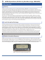
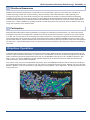
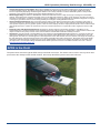
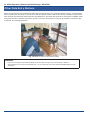
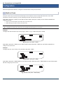
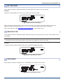
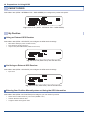
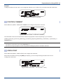
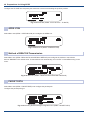
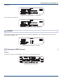
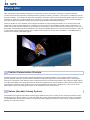
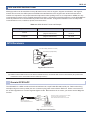
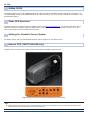
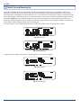
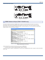
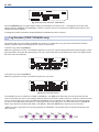

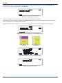
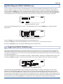
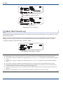
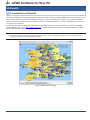
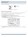
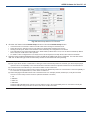
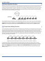
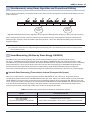
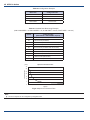
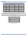
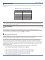
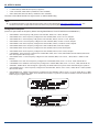
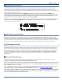
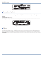
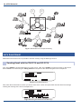
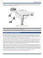
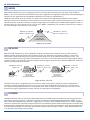
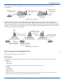
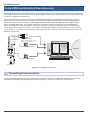
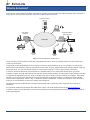
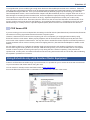
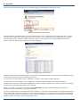
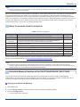
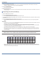
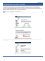
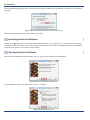
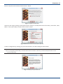
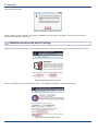
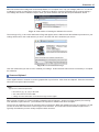

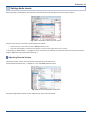
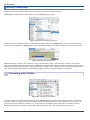
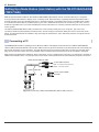
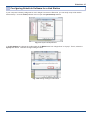
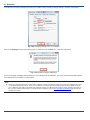
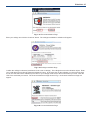
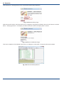
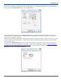
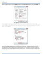
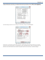
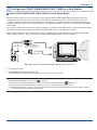
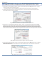
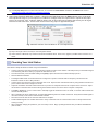
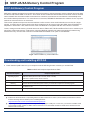
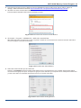

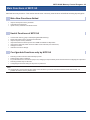
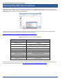
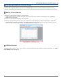
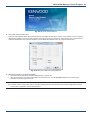
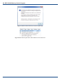
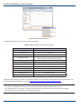
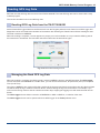
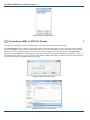
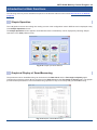
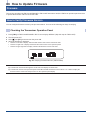
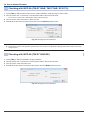
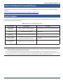

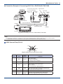
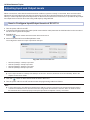
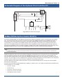
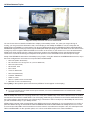


![TH-D72A TH-D72E - [::] Kenwood ASC](http://vs1.manualzilla.com/store/data/006270806_1-4dc3de1ae141fc10b999e73ed81977d3-150x150.png)