1
TM-D710GA/ TM-D710GE
144/440 MHz FM DUAL BANDER/
144/430 MHz FM DUAL BANDER
INSTRUCTION MANUAL
144/440 MHz FM DOUBLE BANDE/
144/430 MHz FM DOUBLE BANDE
MODE D’EMPLOI
DOBLE BANDA DE 144/440 MHz EN FM/
DOBLE BANDA DE 144/430 MHz EN FM
MANUAL DE INSTRUCCIONES
Only basic operations are explained in this instruction manual.
For a detailed explanation on the operations, refer to the PDF file
supplied on the CD-ROM.
Seules les fonctions de base sont expliquées dans ce mode
d’emploi. Pour le détail sur les autres opérations, reportez-vous
au fichier PDF à votre disposition sur le CD-ROM.
En este manual de instrucciones solamente se explican las
operaciones básicas. Si desea obtener una descripción detallada
de las operaciones, consulte el archivo PDF correspondiente
incluido en el CD-ROM.
© B62-2562-00 (K, E)
09 08 07 06 05 04 03 02 01 00
144/440 MHz FM DUAL BANDER/
144/430 MHz FM DUAL BANDER
ENGLISH
TM-D710GA/ TM-D710GE
INSTRUCTION MANUAL
NOTIFICATION
This equipment complies with the essential requirements of Directive
1999/5/EC.
The use of the warning symbol
means the equipment is subject to
restrictions of use in certain countries.
This equipment requires a licence and is intended for use in the
countries as below.
AT
IT
GB
SK
BE
LI
CY
SI
DK
LU
CZ
BG
FI
NL
EE
RO
FR
NO
HU
HR
DE
PT
LV
GR
ES
LT
IS
SE
MT
IE
CH
PL
ISO3166
Firmware Copyrights
The title to and ownership of copyrights for firmware embedded in
KENWOOD product memories are reserved for JVC KENWOOD
Corporation.
THANK YOU
We are grateful you decided to purchase this KENWOOD FM transceiver.
KENWOOD always provides Amateur Radio products which surprise and excite
serious hobbyists. This transceiver is no exception. KENWOOD believes that this
product will satisfy your requirements for both voice and data communications.
FEATURES
This transceiver has the following main features:
•
•
•
•
•
•
•
A built-in GPS receiver unit.
A built-in 5000 point GPS Logger.
Has a built-in TNC which conforms to the AX.25 protocol. With a portable computer,
allows you to enjoy Packet operation quite easily.
Includes a program for dealing with data formats supported by Automatic Packet/
Position Reporting System (APRS®).
Enhanced Programmable Memory (PM) channels store virtually entire current operating
environments for your quick recall.
Contains a total of 1000 Memory channels to program frequencies and other various
data. Allows each Memory channel to be named using up to 8 alphanumeric
characters.
Continuous Tone Coded Squelch System (CTCSS) or Digital Code Squelch (DCS)
rejects unwanted calls from other stations.
WRITING CONVENTIONS FOLLOWED IN THIS MANUAL
The writing conventions described below have been followed to simplify
instructions and avoid unnecessary repetition.
Instruction
Action
Press [KEY].
Momentarily press KEY.
Press [KEY] (1s).
Press and hold KEY for 1 second or longer.
Press [KEY1], [KEY2].
Press KEY1 momentarily, release KEY1, then press
KEY2.
Press [F], [KEY].
Press the F key to enter Function mode, then press
KEY to access its secondary function.
Press [KEY] + Power ON.
With the transceiver power OFF, press and hold KEY
while turning the transceiver power ON.
Information on Disposal of Old Electrical and Electronic Equipment and Batteries (applicable
for countries that have adopted separate waste collection systems)
Products and batteries with the symbol (crossed-out wheeled bin) cannot be disposed
as household waste.
Old electrical and electronic equipment and batteries should be recycled at a facility
capable of handling these items and their waste by products.
Contact your local authority for details in locating a recycle facility nearest to you.
Proper recycling and waste disposal will help conserve resources whilst preventing
detrimental effects on our health and the environment.
NOTICES TO THE USER
One or more of the following statements may be applicable:
FCC WARNING
This equipment generates or uses radio frequency energy. Changes or modifications to this
equipment may cause harmful interference unless the modifications are expressly approved in the
instruction manual. The user could lose the authority to operate this equipment if an unauthorized
change or modification is made.
INFORMATION TO THE DIGITAL DEVICE USER REQUIRED BY THE FCC
This equipment has been tested and found to comply with the limits for a Class B digital device,
pursuant to Part 15 of the FCC Rules. These limits are designed to provide reasonable protection
against harmful interference in a residential installation.
This equipment generates, uses and can generate radio frequency energy and, if not installed and
used in accordance with the instructions, may cause harmful interference to radio communications.
However, there is no guarantee that the interference will not occur in a particular installation. If
this equipment does cause harmful interference to radio or television reception, which can be
determined by turning the equipment off and on, the user is encouraged to try to correct the
interference by one or more of the following measures:
• Reorient or relocate the receiving antenna.
• Increase the separation between the equipment and receiver.
• Connect the equipment to an outlet on a circuit different from that to which the receiver is
connected.
• Consult the dealer for technical assistance.
WHEN CONDENSATION OCCURS INSIDE THE TRANSCEIVER
Condensation may occur inside the transceiver in such a case where the room is warmed using a
heater on cold days or where the transceiver is quickly moved from a cold room to a warm room.
When condensation occurs, the microcomputer and/or the transmit/receive circuits may become
unstable, resulting in transceiver malfunction. If this happens, turn OFF the transceiver and just
wait for a while. When the condensation droplets disappear, the transceiver will function normally.
◆ EXPLOSIVE ATMOSPHERES (GASES, DUST, FUMES, etc.)
Turn OFF your transceiver while taking on fuel or while parked in gasoline service stations. Do
not carry spare fuel containers in the trunk of your vehicle if your transceiver is mounted in the
trunk area.
◆ INJURY FROM RADIO FREQUENCY TRANSMISSIONS
Do not operate your transceiver when somebody is either standing near to or touching the
antenna, to avoid the possibility of radio frequency burns or related physical injury.
◆ DYNAMITE BLASTING CAPS
Operating the transceiver within 150 m (500 feet) of dynamite blasting caps may cause them
to explode. Turn OFF your transceiver when in an area where blasting is in progress, or where
“TURN OFF TWO-WAY RADIO” signs have been posted. If you are transporting blasting caps
in your vehicle, make sure they are carried in a closed metal box with a padded interior. Do not
transmit while the caps are being placed into or removed from the container.
i
PRECAUTIONS
Observe the following precautions to prevent fire, personal injury, and transceiver
damage.
• When operating mobile, do not attempt to configure the transceiver while driving; it is too
dangerous.
• Do not transmit with high output power for extended periods. The transceiver may
overheat.
• Do not disassemble or modify the transceiver for any reason, unless instructed by this
manual or by KENWOOD documentation.
• Do not expose the transceiver to long periods of direct sunlight, nor place it near heating
appliances.
• Do not place the transceiver in excessively dusty, humid, or wet areas, nor on unstable
surfaces.
• If an abnormal odor or smoke is detected coming from the transceiver, switch the
transceiver power off immediately, and contact a KENWOOD service station or your
dealer.
• Use of the transceiver while you are driving may be against traffic laws. Please check
and observe the vehicle regulations in your area.
• Do not use options not specified by KENWOOD.
◆ The transceiver is designed for a 13.8 V DC (±15%) power source! Never use a 24 V battery to
power the transceiver. Check the battery polarity and voltage of the vehicle before installing the
transceiver.
◆ Use only the supplied DC power cable or a KENWOOD optional DC power cable.
◆ Do not insert metal objects into the cooling fan.
◆ Do not cut and/or remove the fuse holder on the DC power cable. Improper connections and/or
current surges may cause smoke or fire.
◆ For passenger safety, install the transceiver securely using the supplied mounting bracket and
screw set so the transceiver will not break loose in the event of a collision.
◆ Various electronic equipment in your vehicle may malfunction if they are not properly protected
from the radio frequency energy which is present while transmitting. Electronic fuel injection,
anti-skid braking, and cruise control systems are typical examples of equipment that may
malfunction. If your vehicle contains such equipment, consult the dealer for the make of vehicle
and enlist his/her aid in determining if they will perform normally while transmitting.
ii
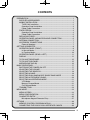
CONTENTS
PREPARATION................................................................................................. 1
SUPPLIED ACCESSORIES ....................................................................... 1
MOBILE INSTALLATION............................................................................. 2
TX/RX Unit Installation .......................................................................... 2
Operation Panel Installation .................................................................. 3
Power Cable Connection ....................................................................... 3
FIXED STATION.......................................................................................... 4
Operation Panel Installation .................................................................. 4
Power Cable Connection ....................................................................... 5
REPLACING FUSES .................................................................................. 6
OPERATION PANEL AND MICROPHONE CONNECTION ....................... 6
ANTENNA CONNECTION.......................................................................... 7
ACCESSORY CONNECTIONS .................................................................. 7
External Speakers ................................................................................. 7
GETTING ACQUAINTED ................................................................................. 8
OPERATION PANEL (FRONT) ................................................................... 8
In Normal Mode..................................................................................... 8
In Function Mode ................................................................................ 10
OPERATION PANEL (REAR & LEFT) ...................................................... 11
DISPLAY ................................................................................................... 12
TX/ RX UNIT REAR PANEL...................................................................... 15
TX/ RX UNIT SUB PANEL ........................................................................ 15
MICROPHONE (MC-59) ........................................................................... 16
BASIC OPERATIONS..................................................................................... 17
SWITCHING THE POWER ON/ OFF ....................................................... 17
ADJUSTING THE VOLUME...................................................................... 17
ADJUSTING THE SQUELCH ................................................................... 18
SELECTING A BAND ............................................................................... 18
SELECTING DUAL BAND MODE/ SINGLE BAND MODE ...................... 20
SELECTING A FREQUENCY BAND........................................................ 20
SELECTING AN OPERATING MODE ...................................................... 21
VFO Mode ........................................................................................... 21
Memory Channel Mode ....................................................................... 22
Call Channel Mode.............................................................................. 22
TRANSMITTING ....................................................................................... 23
MENU MODE ................................................................................................. 24
MENU ACCESS........................................................................................ 24
MENU CONFIGURATION......................................................................... 25
CHARACTER ENTRY............................................................................... 36
Microphone Keypad Character Entry .................................................. 37
OPTIONS ....................................................................................................... 38
MEMORY CONTROL PROGRAM MCP-6A ............................................. 38
CONNECTING THE PG-5G/ PG-5H INTERFACE CABLES .................... 39
iii
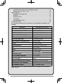
CONNECTING THE PG-5F EXTENSION CABLE.................................... 40
INSTALLING THE VGS-1 UNIT ................................................................ 41
MAINTENANCE ............................................................................................. 42
GENERAL INFORMATION ....................................................................... 42
SERVICE .................................................................................................. 42
SERVICE NOTE ....................................................................................... 42
CLEANING ............................................................................................... 42
TROUBLESHOOTING .............................................................................. 43
SPECIFICATIONS .......................................................................................... 45
For a detailed explanation on the operation, refer to the PDF file supplied on the
CD-ROM.
Operation
File name (TM-D710G_)
CONTENTS
00_CONTENTS_EN.pdf
OPERATING THROUGH REPEATERS
01_REPEATER_EN.pdf
MEMORY CHANNELS
02_MEMORY CHANNEL_EN.pdf
PROGRAMMABLE MEMORY (PM)
03_PM CHANNEL_EN.pdf
SCAN
04_SCAN_EN.pdf
CTCSS/ DCS/ CROSS TONE
05_SIGNALING_EN.pdf
DUAL TONE MULTI-FREQUENCY (DTMF)
06_DTMF_EN.pdf
®
EchoLink
07_EchoLink_EN.pdf
OTHER OPERATIONS
08_OTHER OPERATIONS_EN.pdf
GPS
09_GPS_EN.pdf
PACKET
10_PACKET_EN.pdf
APRS®
11_APRS_EN.pdf
TRANSCEIVER RESET
12_RESET_EN.pdf
VGS-1 (OPTIONAL) OPERATION
13_VGS_EN.pdf
CCROSS-BAND/ LOCKED-BAND OPERATION
(TM-D710GA ONLY)
14_CROSS BAND_REP_TM-D710GA_
EN.pdf
WIRELESS OPERATION (TM-D710GA ONLY)
15_WIRELESS_TM-D710GA_EN.pdf
WEATHER ALERT (TM-D710GA ONLY)
16_WEATHER ALERT_TM-D710GA_EN.pdf
SKY COMMAND SYSTEM II
17_SKY COMMAND_EN.pdf
Note: Operation files are available in PDF file format. To read the files, you must use
Adobe® Reader®.
iv
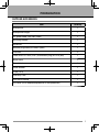
PREPARATION
SUPPLIED ACCESSORIES
Item
Quantity
Microphone
1
Microphone hanger
1
DC power cable (with 20 A fuses)
1
Mounting bracket
1
Screw set
1
Modular plug cable (for PANEL jacks)
1
Line filter
2
Cable with a 2.5 mm (1/10") 3-conductor plug (for GPS jack)
1
Base stand
1
Panel holder
1
Panel bracket
1
Fuse (15 A)
1
Warranty Card
1
Instruction manual
1
CD-ROM (For a detailed explanation on the operations)
1
1
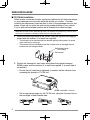
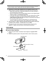
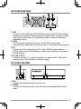
MOBILE INSTALLATION
■ TX/ RX Unit Installation
Select a safe, convenient location inside your vehicle that will minimize danger
to your passengers and yourself while the vehicle is in motion. Consider
installing the transceiver under the dash in front of the passenger seat so that
knees or legs will not strike the radio during sudden braking of your vehicle.
Try to a pick well-ventilated location that is shielded from direct sunlight.
Note: You may experience interference on the GPS receiver when using in or around
438.8 MHz (A band) and/or 443.8 MHz (B band). To eliminate the interference, ensure that the
TX/RX unit is installed at a location separate from the Operation Panel.
1 Install the mounting bracket in the vehicle using the supplied self-tapping
screws and flat washers (4 of each are supplied).
•
•
The bracket can be mounted with the bracket opening facing down, for under
dash mounting, or facing up.
The bracket must be installed so that the 3 screw slots on the edge of each
bracket side are facing the back.
Self-tapping screw
(5 x 16 mm)
Flat washer
2 Position the transceiver, then insert and tighten the supplied hexagon
SEMS screws and flat washers (4 of each are supplied, 2 for each side of
the bracket).
•
Ensure that all hardware is tightened, to prevent vehicle vibration from
loosening the bracket or TX/ RX unit.
SEMS screw (M4 x 10 mm)
•
2
Set an appropriate angle for the TX/ RX unit, using the 3 screw slots on
the rear edge of each bracket side.
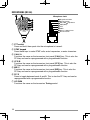
■ Operation Panel Installation
Tapping screw
(4 mm x 12 mm)
Note: Install the operation panel in a location where it
can easily receive satellite signals.
Install the operation panel so that it is standing
perpendicular.
Flat washer
Panel
bracket
Do not install the bracket close to an air bag.
1 Clean and dry the installation location.
Adhesive tape
2 Remove the release paper from the base
of the panel bracket, then secure it in place
using the 3 supplied self-tapping screws.
•
•
Allow the panel to set for a while, to ensure
it remains fast. Otherwise, vibrations may
occur.
After removing the release paper, it cannot be
reused.
Panel holder
SEMS screw
(M4 x 10 mm)
3 Attach the panel holder to the panel bracket
using the 2 supplied SEMS screws.
4 Attach the operation panel to the panel
holder so that it locks in place.
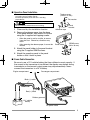
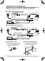
■ Power Cable Connection
Be sure to use a 12 V vehicle battery that has sufficient current capacity. If
the current to the transceiver is insufficient, the display may darken during
transmission or the transmit output power may drop excessively. Never
connect the transceiver to a 24 V battery.
Engine compartment
Passenger compartment
Black (‒) cable
Fuse holder
Red (+) cable
Fuse holder
Rubber grommet
12 V vehicle
battery
DC power cable
3
Note: If you use the transceiver for a long period when the vehicle battery is not fully charged
or when the engine is OFF, the battery may become discharged and will not have sufficient
reserves to start the vehicle. Avoid using the transceiver under these conditions.
1 Route the DC power cable supplied with the transceiver directly to the
vehicle’s battery terminals using the shortest path from the transceiver.
•
•
•
•
When using a noise filter, it should be installed with an insulator to prevent it
from touching metal on the vehicle.
We do not recommend using a cigarette lighter socket as some cigarette lighter
sockets introduce an unacceptable voltage drop.
If the power cable must be routed through a hole in the vehicle chassis or body,
for example in the firewall at the front of the passenger compartment, use a
rubber grommet to protect the cable from abrasion. Dismantle the fuse holder to
pass the cable through the firewall.
The entire length of the cable must be dressed so it is isolated from heat,
moisture, and the engine secondary (high voltage) ignition system/ cables.
2 After the cable is in place, wind heat-resistant tape around the fuse holder
to protect it from moisture. Tie down the full run of cable.
3 To prevent the risk of short circuits, disconnect other wiring from the
negative (–) battery terminal before connecting the transceiver.
FIXED STATION
■ Operation Panel Installation
1 Attach the panel holder to the base stand using the 2 supplied SEMS
screws.
2 Attach the operation panel to the panel holder so that it locks in place.
Operation panel
SEMS screw (M4 x 10 mm)
Panel holder
Base stand
4
■ Power Cable Connection
In order to use this transceiver for fixed station operation, you will need a
separate 13.8 V DC power supply that must be purchased separately. The
recommended current capacity of the power supply is 13 A.
Note: Do not plug the DC power supply into an AC outlet until you make all connections.
Black (‒) cable
Fuse holder
Red (+) cable
Fuse holder
DC power cable
Regulated DC power supply
1 Ensure that the transceiver and DC power supply are both OFF.
2 Connect the DC power cable to the regulated DC power supply and ensure
that the polarities are correct (Red: positive, Black: negative).
•
•
Use the supplied DC power cable to connect the transceiver to a regulated
power supply. Do not directly connect the transceiver to an AC outlet.
Do not substitute the cable with smaller gauge wires.
3 Connect the DC power cable to the transceiver.
•
Press the connectors firmly together until the locking tab clicks.
Note: For your transceiver to fully exhibit its performance capabilities, we recommend using an
optional PS-60 (20.5 A, 25% duty cycle) power supply.
5
REPLACING FUSES
If the fuse blows, determine the cause, then correct the problem. After the
problem is resolved, replace the fuse. If newly installed fuses continue to blow,
disconnect the power cable and contact your authorized KENWOOD dealer or an
authorized KENWOOD service center for assistance.
Fuse Location
Fuse Current Rating
Transceiver
(located on the DC connector)
15 A
Supplied DC power cable
20 A
Only use fuses of the specified type and rating; otherwise the transceiver could be damaged.
Fuse
Fuse holder
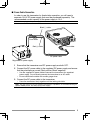
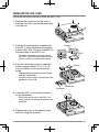
OPERATION PANEL AND MICROPHONE CONNECTION
Plug the microphone plug into the MIC jack, then connect the Operation panel to
the TX/ RX unit with the supplied cable.
•
Attach the microphone hanger to an appropriate position using the screws included in
the screw set.
Microphone
TX/ RX unit
Installing the Line Filter
Install the line filters
approximately 3 cm from the
connectors.
Approx. 3 cm
MIC jack
Panel jack
Line filter
Modular plug cable
Line filter
6
Operation panel
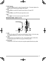
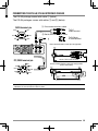
ANTENNA CONNECTION
Before operating, you must first install an efficient, well-tuned antenna. The
success of your installation will depend largely on the type of antenna and its
correct installation. The transceiver can give excellent results if the antenna
system and its installation are given careful attention.
Use a low-loss coaxial feed line that also has a characteristic impedance of
50 , to match the transceiver input impedance. Coupling the antenna to the
transceiver via feed lines having an impedance other than 50 reduces the
efficiency of the antenna system and can cause interference to nearby broadcast
television receivers, radio receivers, and other electronic equipment.
◆ Transmitting without first connecting an antenna or other matched load may damage the
transceiver. Always connect the antenna to the transceiver before transmitting.
◆ All fixed stations should be equipped with a lightning arrester to reduce the risk of fire, electric
shock, and/or transceiver damage.
Antenna terminal
To antenna
Feed line connector
ACCESSORY CONNECTIONS
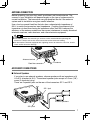
■ External Speakers
If you plan to use external speakers, choose speakers with an impedance of 4
to 8 (standard is 8 ). The external speaker jacks accept a 3.5 mm (1/8")
mono (2-conductor) plug.
There are 2 speaker jacks on the rear of the transceiver: SP 1 and SP 2.
SP 1 jack
External speakers
SP 2 jack
7
GETTING ACQUAINTED
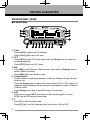
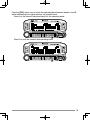
OPERATION PANEL (FRONT)
■ In Normal Mode
a CALL
Press [CALL] to select the Call channel.
Press [CALL] (1s) to start Call scan.
b VFO
Press [VFO] to enter VFO mode, then rotate the Tuning control to select an
operating frequency.
Press [VFO] (1s) to start VFO scan.
c MR
Press [MR] to enter Memory Channel mode, then rotate the Tuning control to
select a Memory channel.
Press [MR] (1s) to start Memory scan.
d Tuning Control
Rotate to select an operating frequency or Memory channel, change the scan
direction, etc.
Press the Tuning control to enter MHz mode (while in VFO or Call mode) or to
toggle the display between the channel name and frequency (while in Memory
Channel mode).
Press Tuning control (1s) to start MHz scan or Group scan.
e KEY
Each time you press [KEY], the Operation Keys mode toggles as follows:
APRS keys ➡ GPS keys ➡ Normal keys
f F
Press [F] to enter Function mode.
Press [F] (1s) to turn the transceiver key lock function ON and OFF.
8
g TONE
Press [TONE] to turn the Tone function ON.
Each time you press [TONE], the function cycles through the following: Tone
ON ➡ CTCSS ON ➡ DCS ON ➡ Cross Tone ON ➡ OFF.
h REV
Press [REV] to turn the Reverse function ON or OFF.
Press [REV] (1s) to turn the Automatic Simplex Checker ON.
i LOW
Press [LOW] to toggle the transmit output power as follows: Middle Power ➡
Low Power ➡ High Power.
j PF1
Press [PF1] to activate its programmable function. The default function is
“Weather Channel” (TM-D710GA)/“Frequency Band Select” (TM-D710GE).
k PF2
Press [PF2] to activate its programmable function. The default function is
“Operation Band Select”.
l BAND SEL (VOL) Control
Rotate the [BAND SEL] control to adjust the speaker volume.
Press the left [BAND SEL] to select the A band. Press the right [BAND SEL]
to select the B band.
Press [BAND SEL] (1s) to toggle between single and dual-band mode.
m SQL Control
Rotate the [SQL] control to adjust the squelch level. Clockwise tightens the
squelch and counterclockwise opens the squelch.
n TNC
Press [TNC] to turn the built-in TNC ON and the APRS (or NAVITRA) mode
ON.
Each time you press [TNC], the mode toggles as follows:
APRS (or NAVITRA) mode ON ➡ PACKET mode ON ➡ TNC OFF.
•
•
When the built-in TNC turns on, “OPENING TNC” appears on the display.
When “OPENING TNC” appears on the display, the mode cannot be changed.
o PM
Press [PM] to enter the PM (Programmable Memory) channel selection mode.
p
Press [ ] to turn the transceiver power ON and OFF.
9
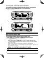
■ In Function Mode
a C.IN
Press [C.IN] to store the current operating frequency to the Call channel.
b M>V
Press [M>V] to copy the current Memory channel or Call channel to the VFO
(memory shift).
c M.IN
Select a Memory channel, then press [M.IN] to store the current operating
frequency in the Memory channel.
d Tuning Control
Press the Tuning control to enter Menu mode.
e F OFF
Press [F OFF] to return Normal mode.
f T.SEL
While Tone, CTCSS, DCS, or Cross Tone is ON, press [T.SEL] to enter Tone,
CTCSS, DCS, or Cross Tone setup mode.
g SHIFT
Press [SHIFT] to enter Offset Direction selection mode. Each time you press
[SHIFT], the offset direction toggles as follows:
plus (+) direction ➡ minus (–) direction ➡ –7.6 MHz (TM-D710GE only) ➡ OFF.
h MUTE
Press [MUTE] to turn the Mute function ON or OFF.
i VISUAL
Press [VISUAL] to turn the Visual Scan function ON and OFF.
j BAND SEL (VOL) Control
Rotate the [BAND SEL] control to adjust the speaker volume.
Press [BAND SEL] to select a frequency band.
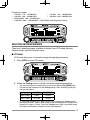
10
k SQL Control
Rotate the [SQL] control to adjust the squelch level. Clockwise tightens the
squelch and counterclockwise opens the squelch.
l DX
Press [DX] to turn the DX PacketClusters Monitor ON and OFF.
m P.IN
Press [P.IN] to enter PM Channel registration mode.
n
Press [ ] to turn the transceiver power ON and OFF.
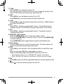
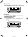
OPERATION PANEL (REAR & LEFT)
a GPS
Connect the external GPS receiver or the Weather Station to this jack using
the supplied cable with a 2.5 mm (1/10") 3-conductor plug.
b COM
This terminal is for connecting to a PC. Use a PG-5G (option) cable when
connecting the built-in TNC to a computer D-SUB terminal.
c Panel jack
Connect the TX/ RX unit to this jack using the supplied Modular plug cable.
11
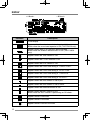
DISPLAY
< A Band >
Indicator
< B Band >
Description
Clock display
Appears when there is a transmission band available.
Blinks when the cross-band repeater is ON (TM-D710GA only).
Appears when there is an operation band available.
Blinks when the wireless remote control is ON (TM-D710GA
only).
Appears when the Tone function is ON.
Appears when the CTCSS function is ON.
Appears when the DCS function is ON.
Appears when the Cross tone setting is “TONE/CTCSS”.
Appears when the Cross tone setting is “DCS/CTCSS”.
Appears when the Cross tone setting is “TONE/DCS”.
Appears when the Cross tone setting is “DCS/OFF”.
Appears when the Shift function is set to plus.
Appears when the Shift function is set to minus.
Appears when the Reverse function is ON.
Appears when the ASC function is ON.
Blinks when the ASC function is performing an OK check.
Appears while in AM mode.
Appears while in FM mode.
Appears while in Narrow FM mode.
12
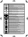
Indicator
Description
Appears when the selected channel is non-registered while in
Memory Input mode.
Appears when the selected channel is registered while in
Memory Input mode.
Displays the Memory channel number.
Appears when the Memory Channel Lockout function is ON.
Appears while using High output power.
Blinks when the temperature protection circuit (transmit power
save) turns on.
Appears while using Middle output power.
Blinks when the temperature protection circuit (transmit power
save) turns on.
Appears while using Low output power.
Displays the operating frequency.
Appears when receiving a busy signal.
Performs as an S meter when receiving a signal and displays
the selected power level while transmitting.
Appears while transmitting.
Appears while using the External data band.
Appears while using the Internal data band.
Appears when the data terminal is set as 9600 bps.
Appears when the mute function is ON.
Appears while making a continuous recording.
Appears while in EchoLink Sysop mode.
Appears when the Key Lock function is ON.
Displays the PM channel number.
Appears when Weather Alert is ON.
Blinks when receiving a signal (TM-D710GA only).
Appears when a message is received.
Appears when the Beacon type is set to “APRS”.
Appears when the Beacon type is set to “NAVITRA”.
13
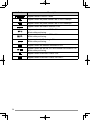
Indicator
Description
Appears while in PACKET mode.
Appears when the packet transfer rate is set to 1200 bps.
Appears when the packet transfer rate is set to 9600 bps.
Appears when the Beacon function is ON.
Appears when the external GPS is ON.
Blinks while positioning.
Appears when the internal GPS is ON.
Blinks while positioning.
Appears when the Track Log is ON.
Blinks while positioning.
Appears when the Weather Instrument is ON.
Appears when the internal GPS and Weather Instrument is ON.
Blinks while positioning.
Appears when Voice Alert is set to “ON”.
Appears when Voice Alert is set to “RX ONLY”.
14
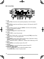
TX/ RX UNIT REAR PANEL
a ANT
Connect an SO-239/M-type (TM-D710GA) or N-type (TM-D710GE) external
antenna to this terminal. When making test transmissions, connect a dummy
load in place of the antenna. The antenna system or load should have an
impedance of 50 .
b DATA
This is the data input/output terminal. Use a PG-5H (option) data
communications cable when connecting to the PC voice input/output terminal.
c PC
This terminal is for connecting to a PC. Use a PG-5G (option) cable or a
PG-5H (option) serial communications cable when connecting to a computer
D-SUB terminal.
d SP (SP 1/ SP 2)
If desired, connect 1 or 2 external speakers for clearer audio. These jacks
accept 3.5 mm (1/8") diameter, 2-conductor plugs.
TX/ RX UNIT SUB PANEL
a MIC
Connect the supplied microphone to this jack.
b PANEL
Connect the Operation panel to this jack using the supplied Modular plug
cable.
15
MICROPHONE (MC-59)
Microphone Jack
Keypad serial data
No Connection
MIC, 600 impedance
GND (MIC)
PTT
GND
DC 8 V, 100 mA max
No Connection
a PTT switch
Press and hold, then speak into the microphone to transmit.
b DTMF keypad
Press these keys to make DTMF calls, enter frequencies, or enter characters.
c CALL/ A
Functions the same as the transceiver front panel [CALL] key. This is also the
PF4 key and can be reprogrammed with a programmable function.
d VFO/ B
Functions the same as the transceiver front panel [VFO] key. This is also the
PF3 key and can be reprogrammed with a programmable function.
e MR/ C
Functions the same as the transceiver front panel [MR] key. This is also the
PF2 key and can be reprogrammed with a programmable function.
f PF/ D
Press to toggle between bands A and B. This is also the PF1 key and can be
reprogrammed with a programmable function.
g UP/ DWN
Functions the same as the transceiver Tuning control.
16
BASIC OPERATIONS
SWITCHING THE POWER ON/ OFF
Press the [ ] switch to switch the transceiver ON.
•
•
The power on message momentarily appears on the display.
If the transceiver power on password has been activated {Menu No.998}, you must first
enter your password before you can operate the transceiver.
Press the [ ] switch again to switch the transceiver OFF.
ADJUSTING THE VOLUME
Rotate the [BAND SEL] (VOL) control of your selected band clockwise to
increase the volume and counterclockwise to decrease the volume.
Note: Some functions of this transceiver, such as the beep and voice announcements, have their
own volume settings. Adjust those settings to your desired values.
17
ADJUSTING THE SQUELCH
Squelch is used to mute the speaker when no signals are present. With the
squelch level set correctly, you will hear sound only while actually receiving a
signal. The higher the squelch level selected, the stronger the signals must be in
order to hear them.
Rotate the [SQL] control of your selected band, when no signals are present, and
select the squelch level at which the background noise is just eliminated.
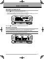
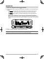
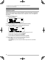
SELECTING A BAND
Press the left [BAND SEL] control to select band A and the right [BAND SEL]
control to select band B.
•
The
icon appears at the top of the band on which you are operating and the
icon appears at the top of the band on which you are currently set to transmit.
Band A (left [BAND SEL] control):
Band B (right [BAND SEL] control):
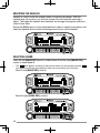
18
Pressing [PF2] allows you to switch the operating band between bands A and B,
while maintaining the original band as the transmit band.
Band A is the transmit band and band B is the operating band:
Band A is both the transmit and operating band:
19
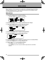
SELECTING DUAL BAND MODE/ SINGLE BAND MODE
You can switch the transceiver between dual band operation and single band
operation by pressing [BAND SEL] (1s) of your selected band.
Dual band mode:
Single band mode (band A only):
Note: You can also turn the center partition bar display off {Menu No. 928}.
SELECTING A FREQUENCY BAND
You can change the default frequency band for bands A and B.
1 Select band A or B by pressing the [BAND SEL] control or [PF2].
2 Press [F], [BAND SEL] of your selected band.
•
•
•
•
•
•
Each time you press [F], [BAND SEL], you cycle to the next frequency band.
The default setting of the [PF1] key also allows you to cycle to the next frequency
band (TM-D710GE).
When masking a band, you are restricted to using only the selectable band.
When receiving 2 signals on the same band, the image interference, sensitivity, etc.,
Performance will decrease.
Band A: 118 >> 144 (default) >> 220 >> 300 >> 430/440 (MHz).
Band B: 144 >> 220 >> 300 >> 430/440 (default) >> 1200 (MHz).
Note: TM-D710GE models use the 430 MHz band and TM-D710GA models use the 440 MHz
band.
20
Frequency ranges:
•
•
•
•
118 MHz: 118 ~ 135.995 MHz
• 144 MHz: 136 ~ 199.995 MHz
220 MHz: 200 ~ 299.995 MHz
• 300 MHz: 300 ~ 399.995 MHz
430/440 MHz: 400 ~ 523.995 MHz
1200 MHz: 800 ~ 1299.990 MHz (TM-D710GA: excluding cellular band)
SELECTING AN OPERATING MODE
There are 3 operating modes available to choose from: VFO mode, Memory
Channel mode, and Call Channel mode.
■ VFO Mode
VFO mode allows you to manually change the operating frequency.
1 Press [VFO] to enter VFO mode.
2 Rotate the Tuning control to select your desired operating frequency.
•
•
•
You can also adjust the frequency by using the microphone [UP]/[DWN] keys.
The default step frequency for the Tuning control varies according to the type
and operating band:
Model
144 MHz
430/440 MHz
TM-D710GA
5 kHz
25 kHz
TM-D710GE
12.5 kHz
25 kHz
To adjust the frequency by a larger amount, you can press the Tuning control
to enter MHz mode. While in MHz mode, rotate the Tuning control to adjust the
frequency in steps of 1 MHz. Press the Tuning control again to exit MHz mode
and adjust the frequency using the normal step frequency.
21
■ Memory Channel Mode
Memory Channel mode allows you to quickly select a frequently used
frequency and related data which you have saved in the transceiver memory.
1 Press [MR] to enter Memory Channel mode.
2 Rotate the Tuning control to select your desired Memory channel.
■ Call Channel Mode
Call Channel mode allows you to quickly select a preset channel to allow
immediate calls on that frequency. The Call channel can be conveniently used
as an emergency channel within your group.
1 Select your desired band (A or B).
•
The Call channel has a dedicated frequency for both bands A and B. The
default frequency for band A is 144 MHz. The default frequency for band B is
430/440 MHz.
2 Press [CALL] to enter Call Channel mode.
•
The
icon appears on the display.
3 Press [CALL] again to return to your previous operating frequency.
22
TRANSMITTING
1 Select your desired band and frequency/channel.
2 Press and hold the microphone [PTT] switch and speak into the microphone to
transmit.
•
•
•
The
icon and the RF power meter appear on the display for the selected
transmit band. The RF power meter shows the relative transmit output power.
The / / icon(s) appear on the display, depending on what output power you
have selected.
Speak into the microphone in your normal voice, while keeping the microphone
approximately 5 cm from your mouth. Speaking too close to the microphone or too
loudly may increase distortion and reduce intelligibility of your signal at the receiving
station.
3 When you finish speaking, release the [PTT] switch.
Note: When the transceiver overheats because of ambient high temperature or continuous
transmission, the protective circuit may function to lower transmit output power.
23
MENU MODE
Many functions on this transceiver are selected or configured through the Menu
instead of physical controls. Once you become familiar with the Menu system,
you will appreciate the versatility it offers.
MENU ACCESS
1 Press [F], Tuning control to access the Menu.
•
The setup category name appears on the display.
2 Rotate the Tuning control to select your desired setup category.
3 Press the Tuning control to set the selected category.
•
The Menu name and number appear on the display.
4 Rotate the Tuning control to select your desired Menu.
5 Press the Tuning control to set the selected Menu.
6 Rotate the Tuning control to select your desired value for the selected Menu.
7 Press the Tuning control to set the selected value.
8 Repeat steps 2 to 7 to set up additional Menus.
•
•
24
Press [ESC] at any time to exit Menu mode.
Press [BACK] at any time to cancel the Menu setup and return to the Menu
selection.
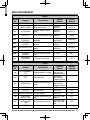
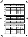
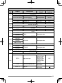
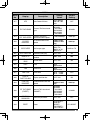
MENU CONFIGURATION
AUDIO
Menu
No.
Display
000
KEY BEEP
001
Description
Setting
Values
Default
Setting
Beep sound
OFF/ ON
ON
BEEP VOLUME
Beep volume level
LEVEL 1 ~
LEVEL 7
LEVEL 5
002
EXT.SPEAKER
External speaker output
mode
MODE 1/
MODE 2
MODE 1
003 1
ANNOUNCE
Voice announcement mode
OFF/ AUTO/
MANUAL
AUTO
004 1
ANNOUNCE
LANGUAGE
Voice announcement
language
ENGLISH/
JAPANESE
ENGLISH
005 1
ANNOUNCE
VOLUME
Voice announcement
volume
LEVEL 1 ~
LEVEL 7
LEVEL 5
006 1
ANNOUNCE SPEED
Voice announcement
speed
SPEED 0 ~
SPEED 4
SPEED 1
007 1
PLAYBACK REPEAT
Recording playback repeat
OFF/ ON
OFF
008 1
PLAYBACK
INTERVAL
Playback repeat interval
time
0 ~ 60 s
10 s
009 1
CONTINUOUS
RECORDING
Continuous Recording
OFF/ ON
OFF
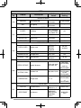
TX/RX
Menu
No.
Display
100
PROGRAMMABLE
VFO
101
STEP
102
MODULATION
Setting
Values
Default
Setting
Programmable VFO setup
Varies with
the selected
frequency band
–
Step frequency
Varies with
the selected
frequency band
–
Modulation/demodulation
mode
Varies with
the selected
frequency band
–
Description
103
VHF AIP
VHF band AIP
OFF/ ON
OFF
104
UHF AIP
UHF band AIP
OFF/ ON
OFF
OFF/ ON
OFF
105
S-METER SQUELCH S-meter squelch
106
S-METER SQL
HANGUP TIME
S-meter squelch hang up
time
OFF/ 125/ 250/
500 ms
OFF
107
MUTE HANGUP
TIME
Mute hang up time setup
OFF/ 125/ 250/
500/ 750/ 1000
ms
OFF
108
BEAT SHIFT
Beat shift
OFF/ ON
OFF
25
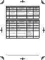
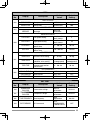
TX/RX
Menu
No.
Display
109
TOT
110
MICROPHONE
SENSITIVITY
111 2
2
112
Description
Setting
Values
Default
Setting
Time-out timer
3/ 5/ 10 min
10 min
Microphone Sensitivity
HIGH/
MEDIUM/ LOW
WEATHER ALERT
Weather alert
OFF/ ON
OFF
AUTO WEATHER
SCAN
Auto weather channel scan
time
OFF/ 15/ 30 /
60 min
OFF
HIGH
(TM-D710GE)
MEDIUM
(TM-D710GA)
MEMORY
Menu
No.
Display
200
MEMORY NAME
201
RECALL METHOD
202
LOCKOUT
203
204
GROUP LINK
EchoLink MEMORY
Description
Setting
Values
Memory name setup
Up to 8
characters
Memory channel recall
method
ALL BANDS/
CURRENT
Memory channel lockout
OFF/ ON
Memory group link
registration
Up to 10 digits
(0 ~ 9)
EchoLink memory setting
Up to 8
characters
for EchoLink
memory name
Default
Setting
–
ALL BANDS
OFF
–
–
Up to 8 digits
for DTMF code
205
26
EchoLink SPEED
EchoLink memory
transmission speed
FAST/ SLOW
FAST
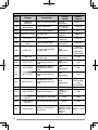
DTMF
Menu
No.
Display
300
DTMF HOLD
301
DTMF MEMORY
Description
Setting
Values
DTMF transmission hold
OFF/ ON
DTMF memory
Up to 8
characters for
DTMF memory
name
Default
Setting
OFF
–
Up to 16 digits
for DTMF code
302
DTMF SPEED
DTMF memory
transmission speed
FAST/ SLOW
303
DTMF PAUSE
DTMF pause code time
100/ 250/ 500/
750/ 1000/
1500/ 2000 ms
304
DTMF KEY LOCK
DTMF key lock
OFF/ ON
FAST
500 ms
OFF
REPEATER
Menu
No.
Display
400
OFFSET FREQUENCY
401
AUTO REPEATER
OFFSET
402
1750 TX HOLD
403 2
REPEATER MODE
404 2
REPEATER TX HOLD
405 2
REPEATER ID
406 2
REPEATER ID TX
Description
Setting
Values
Default
Setting
Offset frequency
See
explanation
Auto Repeater Offset
OFF/ ON
ON
Transmission hold when
OFF/ ON
transmitting a 1750 Hz tone
OFF
Repeater mode
CROSS BAND/
LOCKED
TX:A-BAND/
LOCKED TX:BBAND
Repeater transmission hold
ON/ OFF
Repeater ID registration
Up to 12
characters
Repeater ID transmission
OFF/ MORSE/
VOICE
–
CROSS BAND
OFF
–
OFF
27
GPS
Menu
No.
Setting
Values
Default
Setting
Datum
WGS-84/ TOKYO
WGS-84
SBAS
Satellite Based
Augmentation System
OFF/ ON
ON
COM OUTPUT
GPS data output to PC
OFF/ ON
OFF
$GPGGA/
$GPGLL/
$GPGSA/
$GPGSV/
$GPRMC/
$GPVTG/
$GPZDA
$GPGGA
$GPGSA
$GPGSV
$GPRMC
OFF/ ON
OFF
Record method
TIME/
DISTANCE/
BEACON
TIME
INTERVAL
Interval time
2 sec ~ 1800
sec
10 sec
DISTANCE
Distance
0.01 ~ 9.99
Display
Description
SETUP 1
DATUM
500
SETUP 2
501
502
SENTENCE
Sentence
TRACK LOG
WRAP WHEN FULL
Wrap when memory full
LOG SETUP
RECORD METHOD
503
0.10
TARGET POINT
504
NAME
LATITUDE
LONGITUDE
Name entry
See explanation
−
Latitude entry
See explanation
−
Longitude entry
See explanation
−
Setting
Values
Default
Setting
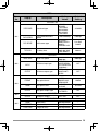
APRS
Menu
No.
Display
Description
BASIC SETTING
MY CALLSIGN
Callsign entry
Up to 9
characters
NOCALL
BEACON TYPE
Beacon type
APRS/
NAVITRA
APRS
APRS lock
OFF/
FREQUENCY/
FREQUENCY
& PTT/
FREQUENCY
& TNC/
FREQUENCY
& PTT & TNC
600
APRS LOCK
28
OFF
APRS
Menu
No.
Display
Description
Setting
Values
Default
Setting
A-BAND
INTERNAL TNC
601
DATA BAND
Data band type
A-BAND/
B-BAND/
TX:A-BAND
RX:B-BAND/
RX:A-BAND
TX:B-BAND
DATA SPEED
Data communications
speed
1200/ 9600 bps
1200 bps
DCD SENSE
DCD sense type
D or RxD
BAND/ BOTH
BAND/
IGNORE DCD
D or RxD
BAND
TX delay time
100/ 150/ 200/
300/ 400/ 500/
750/ 1000 ms
200 ms
TX DELAY
GPS PORT
BAUD RATE
602
INPUT
OUTPUT
Baud rate speed
2400/ 4800/
9600 bps
GPS data input type
OFF/ GPS/
WEATHER(Da
vis)/ WEATHER
(PeetBros)
OFF
GPS data output type
OFF/
WAYPOINT/
DGPS
OFF
NMEA
4800 bps
WAYPOINT
FORMAT
Way point format
NMEA/
MAGELLAN/
KENWOOD
NAME
Way point name
6-CHAR ~
9-CHAR
Way point output type
ALL/ LOCAL/
FILTERED
ALL
OFF/ ON
OFF
603
OUTPUT
604
6-CHAR
COM PORT
OUTPUT
COM port output
MY POSITION
605
NAME
LATITUDE
LONGITUDE
Name entry
See explanation
−
Latitude entry
See explanation
−
Longitude entry
See explanation
−
29
APRS
Menu
No.
Display
Setting
Values
Description
Default
Setting
BEACON INFORMATION
606
SPEED
Speed information setup
OFF/ ON
ON
ALTITUDE
Altitude information setup
OFF/ ON
ON
POSITION
AMBIGUITY
Position ambiguity mode
OFF/ 1-DIGIT ~
4-DIGIT
OFF
POSITION COMMENT
607
POSITION
COMMENT
Position comment
See explanation
Off Duty
STATUS TEXT
608
TEXT
TX RATE
See
explanation
Status text
Status text TX rate
−
OFF/ 1/1 ~ 1/8
OFF
Position limit
See explanation
OFF
Packet filter type
WEATHER/
DIGI/ MOBILE/
OBJECT/
NAVITRA/
1-WAY/
OTHERS
Checked all
See explanation
W
(KENWOOD icon)
PACKET FILTER
POSITION LIMIT
609
TYPE
STATION ICON
610
STATION ICON
Station icon
BEACON TX ALGORITHM
METHOD
611
INITIAL INTERVAL
Method
MANUAL/
PTT/ AUTO/
SmartBeaconing
MANUAL
Initial interval time
0.2/ 0.5/ 1/ 3/
5/ 10/ 20/ 30/
60 min
3 min
DECAY ALGORITHM Decay algorithm
PROPORTIONAL
PATHING
612
Proportional pathing
OFF/ ON
ON
OFF/ ON
ON
PACKET PATH
TYPE
Packet path type
See explanation
NETWORK
613
30
NETWORK
Network
Up to 9
characters
APRS(APK102)
APRS
Menu
No.
Display
Setting
Values
Description
Default
Setting
VOICE ALERT
614
VOICE ALERT
Voice alert
OFF/ ON
CTCSS FREQUENCY CTCSS frequency
See explanation
OFF
100.0 Hz
WEATHER STATION
615
TX
TX INTERVAL
616
617
Weather TX
OFF/ ON
OFF
Weather TX interval time
5/ 10/ 30 min
5 min
DIGIPEAT (MY CALL)
DIGIPEAT
Digipeat
OFF/ ON
OFF
UI CHECK
TIME
UI check time
0 ~ 250 sec
28 sec
UIDIGI
618
UIDIGI
ALIASES
UIDIGI
See explanation
UIFLOOD
UIFLOOD
619
ALIASES
UIFLOOD
See explanation
SUBSTITUTION
UITRACE
620
UITRACE
UITRACE
See explanation
ALIASES
621
USER PHRASES
USER PHRASES
User phrases
See explanation
AUTO MESSAGE REPLY
REPLY
Reply message
OFF/ ON
(DELAY TIME
NONE)/ ON
(DELAY TIME
10 sec)/ ON
(DELAY TIME
30 sec)
Auto message reply text
Up to 50
characters
Reply to
Up to 9
characters
622
TEXT
REPLY TO
OFF
−
31
APRS
Menu
No.
Display
Setting
Values
Description
Default
Setting
GROUP FILTERING
623
MESSAGE
BLN
Message group
Up to 59
characters
ALL,QST,CQ,KWD
BLN group
Up to 29
characters
−
SOUND
624
RX BEEP
RX Beep
OFF/ MESSAG
E ONLY/ MINE/
ALL NEW/ ALL
ALL
TX BEEP
TX Beep
OFF/ ON
OFF
SPECIAL CALL
Special call
Up to 9
characters
APRS VOICE
APRS voice
OFF/ ON
−
ON
INTERRUPT DISPLAY
DISPLAY AREA
OFF/ HALF/
ENTIRE/
ENTIRE
ALWAYS
Display area
625
AUTO BRIGHTNESS Auto brightness
CHANGE COLOR
INTERRUPT TIME
ENTIRE
ALWAYS
OFF/ ON
ON
Change color
OFF/ ON
ON
Interrupt time
3/ 5/ 10 sec/
INFINITE
10 sec
DISPLAY UNIT 1
Speed/ distance
mi/h, mile/ km/h,
km/ knots, nm
ALTITUDE, RAIN
Altitude/ rain
feet, inch/ m, mm
TEMPERATURE
Temperature
°F/ °C
SPEED, DISTANCE
626
mi/h, mile
(TM-D710GA)
km/h, km
(TM-D710GE)
feet, inch
(TM-D710GA)
m, mm
(TM-D710GE)
°F
(TM-D710GA)
°C
(TM-D710GE)
DISPLAY UNIT 2
POSITION
Position format
dd°mm. mm’/
dd°mm’ ss. s”
dd°mm. mm’
Grid format
MAIDENHEAD
GRID/ SAR
GRID (CONV)/
SAR GRID
(CELL)
MAIDENHEAD
GRID
627
GRID FORMAT
32
APRS
Menu
No.
Display
Setting
Values
Description
Default
Setting
NAVITRA GROUP
628
GROUP MODE
Group mode
OFF/ ON
OFF
GROUP CODE
Group code
3 characters
000
NAVITRA MESSAGE
629
MESSAGE
Up to 20
characters
Message
−
SMARTBEACONING 1
630
LOW SPEED
Low speed setting
2 ~ 30 <mi/h,
km/h, knots>
5
HIGH SPEED
High speed setting
2 ~ 90 <mi/h,
km/h, knots>
70
SLOW RATE
Low speed transmission
interval time
1 ~ 100 min
30 min
FAST RATE
High speed transmission
interval time
10 ~ 180 sec
120 sec
TURN ANGLE
Driving direction change,
minimum value setting
5 ~ 90 deg
TURN SLOPE
Driving direction change,
additional value setting
1 ~ 255
(10deg/speed)
Minimum time delay
between each beacon
transmission
5 ~ 180 sec
SMARTBEACONING 2
631
TURN TIME
28 deg
26
(10deg/speed)
30 sec
QSY (FREQUENCY)
632
QSY IN STATUS
QSY in Status
OFF/ ON
OFF
TONE/NARROW
Tone/ Narrow
OFF/ ON
OFF
Shift/ Offset
OFF/ ON
OFF
SHIFT/OFFSET
SKY CMD
Menu
No.
Display
700
COMMANDER
CALLSIGN
Commander callsign
Up to 9
characters
NOCALL
701
TRANSPORTER
CALLSIGN
Transporter callsign
Up to 9
characters
NOCALL
702
TONE FREQUENCY
Tone frequency
See
explanation
88.5Hz
703
SKY COMMAND
SKY command
OFF/
COMMANDER/
TRANSPORTER
Description
Setting
Values
Default
Setting
OFF
33
AUX 2
Menu
No.
Display
900
POWER ON
MESSAGE
901
BRIGHTNESS
Description
Setting
Values
Default
Setting
Power on message setup
Up to 8
characters
HELLO !!
Display brightness
OFF/ LEVEL 1
~ LEVEL 8
LEVEL 8
902
AUTO BRIGHTNESS Display auto brightness
OFF/ ON
OFF
903
BACKLIGHT COLOR Backlight color
AMBER/
GREEN
AMBER
Display contrast
LEVEL 1 ~
LEVEL 16
LEVEL 8
Display reverse mode
POSITIVE/
NEGATIVE
POSITIVE
See
explanation
904
CONTRAST
905
DISPLAY REVERSE
MODE
WX CH
(TM-D710GA)
906
PANEL PF1
PF1 key programmable
function value
907
PANEL PF2
PF2 key programmable
function value
See
explanation
CTRL
908
MIC PF1(PF)
Microphone PF1 key
programmable function
value
See
explanation
A/B
909
MIC PF2(MR)
Microphone PF2 key
programmable function
value
See
explanation
MR
910
MIC PF3(VFO)
Microphone PF3 key
programmable function
value
See
explanation
VFO
911
MIC PF4(CALL)
Microphone PF4 key
programmable function
value
See
explanation
912
MIC KEY LOCK
Microphone key lock
OFF/ ON
OFF
913
SCAN RESUME
Scan resume method
TIME/
CARRIER/
SEEK
TIME
914
SCAN TIME
RESTART
Time operate restart time
1 ~ 10 sec
5 sec
915
SCAN CARRIER
RESTART
Carrier operate restart time
1 ~ 10 sec
2 sec
Number of Channels for
Visual Scan
MODE 1 : 31ch/
MODE 2 : 61ch/
MODE 3 : 91ch/
MODE 4 :
181ch
916
34
VISUAL SCAN
FRQ.BAND
(TM-D710GE)
CALL
(TM-D710GA)
1750
(TM-D710GE)
MODE 2 : 61ch
AUX 2
Menu
No.
Display
917
APO
Description
Setting
Values
Default
Setting
Auto Power Off time
OFF/ 30/ 60/
90/ 120/ 180
min
OFF
B-BAND
918
EXT. DATA BAND
External TNC data band
type
A-BAND/
B-BAND/
TX:A-BAND
RX:B-BAND/
RX:A-BAND
TX:B-BAND
919
EXT. DATA SPEED
External TNC data
communications speed
1200/ 9600 bps
1200 bps
920
PC PORT
BAUDRATE
PC terminal baud rate
speed
9600/ 19200/
38400/ 57600
bps
9600 bps
921
SQC SOURCE
SQC output type
OFF/ BUSY/
SQL/ TX/
BUSY or TX/
SQL or TX
BUSY or TX
922
AUTO PM STORE
Automatic PM entry
OFF/ ON
ON
Personal Identification
Number
000 ~ 999
000
Answer back
OFF/ ON
ON
923 2
REMOTE ID
924 2
REMOTE ANSWER
BACK
925
DATE
Date
See
explanation
–
926
TIME
Clock time
See
explanation
–
927
TIME ZONE
Time zone
UTC + 14:00 ~
UTC − 14:00
UTC
928
DISPLAY
PARTITION BAR
Display partition bar
OFF/ ON
ON
929
COM PORT
BAUDRATE
COM terminal baud rate
speed
9600/ 19200/
38400/ 57600
bps
9600 bps
Internal TNC data band
(PACKET)
A-BAND/
B-BAND/
TX:A-BAND
RX:B-BAND/
RX:A-BAND
TX:B-BAND
A-BAND
Power on password
OFF/ ON
Reset
VFO RESET/
PARTIAL
RESET/
PM RESET/
FULL RESET
930
INT. DATA BAND
(PACKET)
998
POWER ON
PASSWORD
999
RESET
OFF
VFO RESET
35
1
2
Available only when the optional VGS-1 unit is installed in the transceiver.
Available only for TM-D710GA.
Note: The default settings are subject to change.
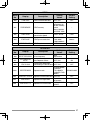
CHARACTER ENTRY
Certain menus require you to enter characters, such as the power on message
and memory names. When character entry is required, a cursor will appear on
the display.
1 Press the Tuning control.
•
The cursor will blink.
2 Rotate the Tuning control to select your desired character.
3 Press the Tuning control to set the selected character.
•
The cursor will move to the next digit.
•
•
•
•
You can move the cursor to the left or right by pressing [] or [].
You can insert one space by pressing [SPACE].
You can insert a character by pressing [INS].
You can delete the selected character by pressing [CLR].
4 Repeat steps 2 and 3 to enter the remaining characters.
•
•
36
Press [ESC] at any time to exit Menu mode.
Press [BACK] at any time to cancel the Menu setup and return to the Menu
selection.
■ Microphone Keypad Character Entry
The microphone keys can also be used to enter characters. Refer to the table
below for characters corresponding to microphone keys.
Key
Character Display (with
each press of the key)
1
Q
Z
1
2
A
B
C
Key
Character Display (with
each press of the key)
7
P
R
S
7
2
8
T
U
V
8
W
X
Y
9
3
D
E
F
3
9
4
G
H
I
4
0
5
J
K
L
5
6
M
N
O
6
(space)
0
Not used
#
–
/
@
For a memory name, status text, and message:
Key
Character Display (with each press of the key)
1
q
z
1
Q
Z
2
a
b
c
2
A
B
C
3
d
e
f
3
D
E
F
4
g
h
i
4
G
H
I
5
j
k
l
5
J
K
L
6
m
n
o
6
M
N
O
7
p
r
s
7
P
R
S
8
t
u
v
8
T
U
V
y
9
W
X
Y
.
,
–
/
)
<
>
9
w
x
0
(space)
0
Not used
#
?
!
’
&
#
%
(
;
:
”
@
The microphone [A] ~ [D] keys have special functions assigned to them:
[A]: Functions the same as [CLR]
[B]: Functions the same as []
[C]: Functions the same as []
[D]: Functions the same as the Tuning control
37
OPTIONS
The following options are available for use with this transceiver:
• MC-45
• MC-59
• MCP-6A
Microphone
Microphone with keypad
Memory Control Program
(web download software)
•
•
•
•
Microphone Plug Adapter
DC Cable (2 m)
Noise Filter
Data Cable
MJ-88
PG-2N
PG-3B
PG-5A
• PG-5G
•
•
•
•
PG-5H
PG-5F
PS-60
SP-50B
• VGS-1
Programming Interface Cable
(2 m)
PC Interface Cable Kit (2 m)
Extension Cable Kit (4 m)
DC Power Supply
External Speaker
Voice Guide & Storage Unit
Note: Optional accessories for use with this transceiver may change, post-production. (New
options may become available and/or current options may be discontinued.) Please refer to the
options catalog(s) for applicable transceivers.
MEMORY CONTROL PROGRAM MCP-6A
The following functions can be set only by using the MCP-6A software:
•
•
•
•
SQC active condition
Input/output level (DATA terminal)
10 MHz mode selection
Power on password value
•
Bitmap setting of the Power ON graphic
Using the MCP-6A software, you can:
•
•
•
•
•
View memory channel groups
Name memory groups
Name PM channels
Save/load settings
Read exported TravelPlus for Repeaters™ files issued from the ARRL™
(There are some version restrictions; refer to the help text of the MCP-6A.)
Print/export memory and various settings in html
•
(TravelPlus for Repeaters is a trademark of ARRL.)
To download the MCP-6A software, go to:
http://www.kenwood.com/i/products/info/amateur/software_download.html
Note: This URL may change without notice.
■ Using the MCP-6A Software
1 Follow the directions of the installer to install the software.
2 Set up the PC COM port and baud rate.
3 The transceiver data is read from the MCP-6A software.
4 Select your desired settings, then write the data to the transceiver.
38
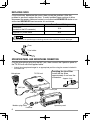
CONNECTING THE PG-5G/ PG-5H INTERFACE CABLES
The PG-5G package comes with cable a (below).
The PG-5H packages comes with cables a and b (below).
DATA terminal pin
SQC
PR9
To PC
audio terminal
PR1
PKS
DE
a Data communications cable
b Serial communications cable
To PC 9-pin
D-SUB terminal
PKD
Data communications cable pin configuration
Pink: To microphone input terminal
PC/ COM terminal pin
NC
NC
RXD
GND
CTS
NC
Green: To line out terminal
Serial communications cable pin configuration
(cross connection)
TXD
RTS
Note: When connecting the regular cable in your vehicle, the terminal may disconnect due to
vibrations. Be sure to lock the cable in place.
39
CONNECTING THE PG-5F EXTENSION CABLE
Using two PG-5F kits, you can extend the cables to the maximum length.
(Components marked with an asterisk * are included in the PG-5F kit.)
■ Connecting Using a Single Extension Kit
External speakers
Microphone
* DC power cables (6 m)
Speaker cables (4 m)
* Extension
connector
* Modular cable (4 m)
Operation panel
* Extension
connector
* Line filter
* Modular cable (4 m)
TX/RX unit
* Line filter
■ Connecting Using Two Extension Kits
External speakers
Speaker cables (4 m)
Microphone
DC power cables (6 m)
Modular cable (4 m) &
extension connector (2 sets)
Operation panel
Modular cable (4 m) &
extension connector (2 sets)
■ Installing the Line Filter
Install the line filter approximately
3 cm from the connector which
attaches to the TX/RX unit.
Approx. 3 cm
TX/RX unit
■ Affixing the Microphone Cable
Lock the microphone cable down
as shown in the illustration.
Self-tapping screw
Flat washer
Microphone
cable
Cable holder
Cushion
40
INSTALLING THE VGS-1 UNIT
Follow the instructions below to install the VGS-1 unit.
1 Remove the 8 screws from the cover of
the base unit, then remove the cover itself
from the unit.
2 From the 5 black cushions supplied with
the VGS-1, select the thickest rectangular
cushion (20 x 30 x 12 mm) and attach it to
the top surface of the VGS-1 unit.
•
Cushion
VGS-1
To prevent interference to the terminal of
the VGS-1, ensure that you attach the thick
square cushion to the base plate surface.
3 From the remaining cushions, select the
thickest square cushion (21 x 21 x 2.5
mm) and attach it to the printed circuit
board.
• The remaining cushions are not used
with this transceiver.
•
Cushion
Ensure that the cushion is placed within the
guidelines on the PCB.
Guidelines
Connector
4 Insert the VGS-1 unit into the connector
on the transceiver.
•
Press down on the top of the VGS-1 unit
to ensure that it is securely attached to the
connector.
5 Replace the cover on the base unit and
secure it using the 8 screws.
41
MAINTENANCE
GENERAL INFORMATION
This product has been factory aligned and tested to specification before shipment.
Attempting service or alignment without factory authorization can void the product
warranty.
SERVICE
When returning this product to your dealer or service center for repair, pack it in
its original box and packing material. Include a full description of the problem(s)
experienced. Include your telephone number along with your name and address
in case the service technician needs to contact you; if available, also include your
fax number and e-mail address. Don’t return accessory items unless you feel they
are directly related to the service problem.
You may return this product for service to the authorized KENWOOD dealer from
whom you purchased it, or any authorized KENWOOD service center. Please do
not send subassemblies or printed circuit boards; send the complete product. A
copy of the service report will be returned with the product.
SERVICE NOTE
If you desire to correspond on a technical or operational problem, please make
your note legible, short, complete, and to the point. Help us help you by providing
the following:
•
•
•
Model and serial number of equipment
Question or problem you are having
Other equipment in your station pertaining to the problem
Do not pack the equipment in crushed newspapers for shipment! Extensive damage may result
during rough handling or shipping.
Note:
◆ Record the date of purchase, serial number and dealer from whom this product was purchased.
◆ For your own information, retain a written record of any maintenance performed on this product.
◆ When claiming warranty service, please include a photocopy of the bill of sale or other
proof-of-purchase showing the date of sale.
CLEANING
To clean the case of this product, use a neutral detergent (no strong chemicals)
and a damp cloth.
42
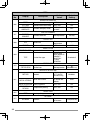
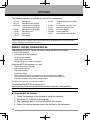
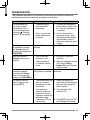
TROUBLESHOOTING
The problems described in this table are commonly encountered operational
malfunctions and are usually not caused by circuit failure.
Problem
Probable Cause
Corrective Action
The transceiver will
not power up after
connecting a 13.8 V
DC power supply and
pressing [ ]. Nothing
appears on the display.
1 The power cable
was connected
backwards.
1 Connect the supplied DC
power cable correctly (red
to + terminal and black to
– terminal).
2 One or more of the
power cable fuses
are open.
2 Look for the cause of
the blown fuse(s). After
inspecting and correcting
any problems, install a
new fuse(s) with the same
ratings.
The frequency cannot
be selected by turning
the Tuning control or
by pressing microphone
[UP]/[DWN].
Memory Recall was
selected.
Press [VFO].
Most keys and the
Tuning control do not
function.
1 One of the Lock
functions is ON.
1 Unlock all of the Lock
functions.
2 The transceiver is
in Channel Display
mode.
2 With the transceiver power
OFF, press [LOW] +
Power ON to exit Channel
Display mode.
No data has been stored Store data in some Memory
Memory channels
in any Memory channel. channels.
cannot be selected
by turning the Tuning
control or by pressing
microphone [UP]/[DWN].
You cannot transmit
even though you are
pressing [PTT].
1 The microphone plug
was not inserted
completely into the
transceiver.
1 Switch the power OFF,
then insert the microphone
plug until the locking tab
clicks in place.
2 You selected a
2 Turn the offset shift
transmit offset that
function OFF.
places the transmit
frequency outside the
allowable range.
3 The external TNC is
transmitting.
3 Press [PTT] after the TNC
has finished transmitting.
43
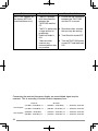
Problem
Probable Cause
“MCP ERR” appears on
the display. (MCP-6A
communications error)
Corrective Action
1 There is a problem
with the connection
between the
TM-D710G and the
PC.
1 Ensure that the connection
between the TM-D710G
and the PC is correct.
2 The PC is performing
a large amount of
processing.
2 Shut down other software
that you may be running.
3 EchoLink mode is
ON.
3 Turn EchoLink mode OFF.
4 There are other
reasons why
communications was
not possible.
4 Turn the TM-D710G power
source OFF and then back
ON.
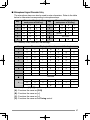
Concerning the received frequency display, an unmodulated signal may be
received. This is according to the set intrinsic frequency form.
<A band>
VxU reception
UxV reception
44
<B band>
(144 MHz + 45.05 MHz) x 2
–
(430 MHz - 49.95 MHz)
=
45.05 MHz, 49.95 MHz
(144 MHz + 45.05 MHz) x 4
–
(430 MHz - 49.95 MHz) x 2
=
45.05 MHz, 49.95 MHz
(430 MHz - 45.05 MHz)
–
(144 MHz + 49.95 MHz) x 2
=
45.05 MHz, 49.95 MHz
(430 MHz - 45.05 MHz) x 2
–
(144 MHz + 49.95 MHz) x 4
=
45.05 MHz, 49.95 MHz
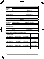
SPECIFICATIONS
Specifications are subject to change without notice due to advancements in
technology.
General
Guaranteed
range
Band
A&B
TX & RX
Band A
Frequency
range
Band B
TM-D710GA
TM-D710GE
144 ~ 148 MHz
144 ~ 146 MHz
430~ 450 MHz
430 ~ 440 MHz
118 ~ 524 MHz
136 ~ 524 MHz
RX
800 ~ 1300 MHz
(TM-D710GA: excluding cellular band)
Mode
F1D/ F2D/ F3E
50
Antenna impedance
Operating temperature range
–20°C ~ +60°C (–4°F ~ +140°F)
Power requirement
13.8 V DC ±15% (Negative ground)
Frequency stability
Within ±5 ppm (–10°C ~ +50°C)
VHF
Current
TX
UHF
Hi
Less than 13.0 A
Mid
Less than 5.5 A
Low
Less than 4.0 A
Hi
Less than 13.0 A
Mid
Less than 6.5 A
Low
Less than 5.0 A
RX
Dimensions
(W x H x D)
Less than 1.2 A (at 2 W audio output)
Without projections
Operation panel: 155 x 70 x 38 mm (6.10 in x 2.76 in x 1.50 in)
TX/ RX unit: 140 x 43 x 142 mm (5.51 in x 1.69 in x 5.59 in)
With projections
Operation panel: 156 x 71 x 56 mm (6.14 in x 2.80" x 2.20 in)
TX/ RX unit: 140 x 44 x 158 mm (5.51 in x 1.73 in x 6.22 in)
Weight (approx.)
Operation panel: 0.3 kg (0.7 lb)
TX/ RX unit: 1.2 kg (2.6 lb)
45
Transmitter
50 W
Hi
RF power
output
Mid
Approx. 10 W
Low
Approx. 5 W
Modulation
Reactance modulation
Maximum frequency deviation
Within ±5 kHz
Spurious radiation
Less than –60 dB
Modulation distortion (300 Hz ~ 3 kHz)
Less than 3%
600
Microphone impedance
Receiver
Circuitry
Intermediate
frequency
Double super heterodyne
1st (Band A/ Band B)
45.05 MHz/ 49.95 MHz
2nd (Band A/ Band B)
455 kHz/ 450 kHz
Sensitivity (144, 430/440 MHz band)
Less than 0.16 µV (-16 dBµ)
Squelch sensitivity
(144, 430/440 MHz band)
Less than 0.1 µV (-20 dBµ)
Selectivity
–6 dB
More than 11 kHz
–50 dB
Less than 30 kHz
Low frequency output (8 )
More than 2 W (at 5% distortion)
Sensitivity (approx.) <excluding 144, 430/440 MHz band>
Frequency range
Band A
Band B
FM: 12 dB SINAD
AM: 10 dB S/N
FM: 12 dB SINAD
118 ~ 135.995 MHz
0.32 µV (-10 dBµ)
0.40 µV (-8 dBµ)
—
136 ~ 173.995 MHz
0.32 µV (-10 dBµ)
0.40 µV (-8 dBµ)
0.32 µV (-10 dBµ)
174 ~ 229.995 MHz
0.40 µV (-8 dBµ)
0.50 µV (-6 dBµ)
0.40 µV (-8 dBµ)
230 ~ 299.995 MHz
5.6 µV (15 dBµ)
5.6 µV (15 dBµ)
5.6 µV (15 dBµ)
300 ~ 349.995 MHz
1.0 µV (0 dBµ)
1.0 µV (0 dBµ)
1.0 µV (0 dBµ)
350 ~ 399.995 MHz
0.56 µV (-5 dBµ)
0.56 µV (-5 dBµ)
0.56 µV (-5 dBµ)
400 ~ 499.995 MHz
0.28 µV (-11 dBµ)
0.36 µV (-9 dBµ)
0.28 µV (-11 dBµ)
500 ~ 523.995 MHz
0.56 µV (-5 dBµ)
0.71 µV (-3 dBµ)
0.56 µV (-5 dBµ)
800 ~ 1239.99 MHz
—
—
7.08 µV (17 dBµ)
1240 ~ 1299.99 MHz
—
—
2.24 µV (7 dBµ)
46