1
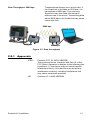
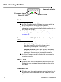
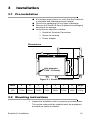
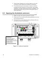
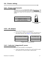
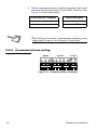
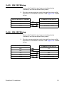
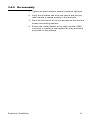
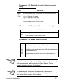
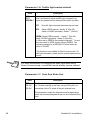
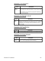
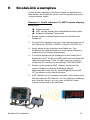
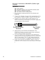
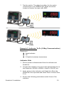
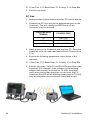
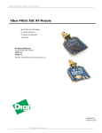
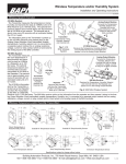
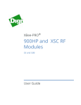
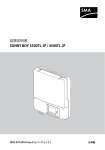
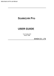
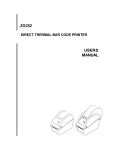
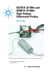
ScaleLink 2
Transceiver
Installation and Technical Instructions
AWT35-501165
Issue AA
scalelink2_i_en_501165.book AWT35-501165
Table of Contents
page
Table of Contents .................................................................................... 3
Chapter 1 General information and warnings ....................................... 5
About this manual ............................................................ 5
Text conventions ....................................................... 5
Special messages ..................................................... 5
Installation ....................................................................... 6
Electrical installation ........................................................ 7
Pluggable equipment ................................................ 7
Wet conditions ........................................................... 8
Routine maintenance ....................................................... 8
Cleaning the machine ...................................................... 9
Training ............................................................................ 9
FCC and EMC declarations of compliance .................... 10
Chapter 2 Introduction .......................................................................... 11
ScaleLink features ......................................................... 11
Specifications & radio principles .................................... 12
Approvals ................................................................ 13
Display & LEDs .............................................................. 14
Chapter 3 Installation ............................................................................ 15
Pre-installation ............................................................... 15
Mounting instructions ..................................................... 15
Opening the ScaleLink enclosure .................................. 16
Power wiring .................................................................. 17
Power requirements ................................................ 17
AC adaptor .............................................................. 17
Indicator “piggy-back” power ................................... 17
Communications wiring ........................................... 18
RS 232 Wiring ......................................................... 19
RS 422 Wiring ......................................................... 19
20 mA Current Loop wiring (passive only) .............. 20
20 mA Current Loop mode switch ........................... 20
Re-assembly ........................................................... 21
Chapter 4 ScaleLink operating modes ................................................ 22
Auto connect mode ........................................................ 22
Direct Connect mode ..................................................... 22
Chapter 5 Set-up mode ......................................................................... 24
ScaleLink 2 Installation
3
Entering set-up mode .....................................................24
Navigating set-up parameters ........................................24
Editing set-up parameters ..............................................24
Exit & save set-up ..........................................................25
Set-up parameters .........................................................26
Diagnostic buttons ..........................................................30
Chapter 6 ScaleLink examples .............................................................31
Chapter 7 Troubleshooting & error messages ....................................35
4
ScaleLink 2 Installation
1
General information and warnings
1.1 About this manual
This manual is divided into chapters by the chapter number and
the large text at the top of a page. Subsections are labeled as
shown by the 1.1 and 1.1.1 headings. The names of the
chapter and the next subsection level appear at the top of
alternating pages of the manual to remind you of where you are
in the manual. The manual name and page numbers appear at
the bottom of the pages.
1.1.1 Text conventions
Key names are shown in bold and reflect the case of the key
being described. This applies to hard keys and onscreen or soft
keys.
Displayed messages appear in bold italic type and reflect the
case of the displayed message.
1.1.2 Special messages
Examples of special messages you will see in this manual are
defined below. The heading words have specific meanings to
alert you to additional information or the relative level of hazard.
ELECTRICAL WARNING!
THIS IS AN ELECTRICAL WARNING SYMBOL.
ELECTRICAL WARNINGS MEAN THAT FAILURE TO
FOLLOW SPECIFIC PRACTICES OR PROCEDURES MAY
RESULT IN ELECTROCUTION, ARC BURNS,
EXPLOSIONS OR OTHER HAZARDS THAT MAY CAUSE
INJURY OR DEATH.
CAUTION!
This is a Caution symbol.
Cautions give information about procedures that, if not
observed, could result in damage to equipment or corruption to
and loss of data.
ScaleLink 2 Installation
5
NOTE: This is a Note symbol. Notes give additional and important
information, hints and tips that help you to use your product.
1.2 Installation
DANGER: RISK OF ELECTRICAL SHOCK. NO USER
SERVICEABLE PARTS. REFER TO QUALIFIED SERVICE
PERSONNEL FOR SERVICE.
CAUTION: Installation, configuration, and servicing are only to
be done by qualified service personnel as authorized by Avery
Weigh-Tronix.
6
ScaleLink 2 Installation
1.3 Electrical installation
CAUTION: Scale Service Technicians handling ScaleLink PCBs
must observe proper electrostatic discharge (ESD) handling
procedures.
CAUTION: The power cable must be connected to an earthgrounded electrical outlet. The electrical supply must have a
circuit breaker with an appropriate rating to protect from overcurrent conditions.
For your protection, all electrical (110V or 230V) equipment used
out of doors or in wet or damp conditions should be supplied
from a correctly fused power source and protected by an
approved ground fault protection device (RCD, GFCI etc.)
IF IN DOUBT SEEK ADVICE FROM A QUALIFIED ELECTRICIAN.
WARNING: ONLY APPROVED ANTENNAS MAY BE USED
WITH THIS DEVICE TO ENSURE COMPLIANCE.
CONTACT THE FACTORY FOR MORE INFO.
THIS EQUIPMENT IS APPROVED ONLY FOR MOBILE
AND BASE STATION TRANSMITTING DEVICES.
ANTENNA(S) USED FOR THIS TRANSMITTER MUST BE
INSTALLED TO PROVIDE A SEPARATION DISTANCE OF
AT LEAST 20 CM FROM ALL PERSONS AND MUST NOT
BE CO-LOCATED OR OPERATING IN CONJUNCTION
WITH ANY OTHER ANTENNA OR TRANSMITTER.
1.3.1 Pluggable equipment
Pluggable equipment must be installed near an easily
accessible socket outlet.
ScaleLink 2 Installation
7
1.3.2 Wet conditions
Under wet conditions, the plug must be connected to the final
branch circuit via an appropriate socket / receptacle designed
for washdown use.
Installations within the USA should use a cover that meets
NEMA 3R specifications as required by the National Electrical
Code under section 410-57. This allows the unit to be plugged
in with a rain tight cover fitted over the plug.
Installations within Europe must use a socket which provides
a minimum of IP56 protection to the plug / cable assembly.
Care must be taken to make sure that the degree of protection
provided by the socket is suitable for the environment.
1.4 Routine maintenance
IMPORTANT: This equipment must be routinely checked for
proper operation and calibration.
Application and usage will determine the frequency of
calibration required for safe operation.
Always turn off the machine and isolate from the power supply
before starting any routine maintenance to avoid the possibility
of electric shock.
8
ScaleLink 2 Installation
1.5 Cleaning the machine
Table 1.1 Cleaning DOs and DON’Ts
DO
DO NOT
Wipe down the outside of
standard products with a clean
cloth, moistened with water and
a small amount of mild detergent
Attempt to clean the inside of the
machine
Spray the cloth when using a
proprietary cleaning fluid
Spray any liquid directly on to
the display windows
Use harsh abrasives, solvents,
scouring cleaners or alkaline
cleaning solutions
1.6 Training
Do not attempt to operate or complete any procedure on a
machine unless you have received the appropriate training or
read the instruction books.
To avoid the risk of RSI (Repetitive Strain Injury), place the
machine on a surface which is ergonomically satisfactory to the
user. Take frequent breaks during prolonged usage.
ScaleLink 2 Installation
9
1.7 FCC and EMC declarations of compliance
United States
This equipment has been tested and found to comply with the limits for a Class A digital device,
pursuant to Part 15 of the FCC Rules. These limits are designed to provide reasonable protection
against harmful interference when the equipment is operated in a commercial environment. This
equipment generates, uses, and can radiate radio frequency energy and, if not installed and used in
accordance with the instruction manual, may cause harmful interference to radio communications.
Operation of this equipment in a residential area is likely to cause harmful interference in which case
the user will be required to correct the interference at his own expense.
Canada
This digital apparatus does not exceed the Class A limits for radio noise emissions from digital
apparatus set out in the Radio Interference Regulations of the Canadian Department of
Communications.
Le présent appareil numérique n’émet pas de bruits radioélectriques dépassant les limites applicables
aux appareils numériques de la Classe A prescrites dans le Règlement sur le brouillage
radioélectrique edicté par le ministère des Communications du Canada.
European Countries
WARNING: This is a Class A product. In a domestic environment, this product may cause radio
interference in which the user may be required to take adequate measures.
10
ScaleLink 2 Installation
2
Introduction
The ScaleLink Wireless Transceiver allows Scale Technicians
with little or no knowledge of radio communications to quickly
and confidently set up wireless systems. Combining trusted
radio frequency technology with scale specific features, the
ScaleLink can be universally connected to any device with a
serial port such as indicators, remote displays, PC computers
and digital summing modules. The ScaleLink can eliminate
costly and time consuming installation steps like trenching,
running wire, and conduit while increasing the range of the
system and decreasing the risk of damage due to transient
voltages and lightning.
Like all Avery Weigh-Tronix products, the ScaleLink is
engineered for durability, functionality, and the versatility of
today’s weighing industry.
The following information is for the exclusive use of Avery
Weigh-Tronix dealers and customers.
2.1 ScaleLink features
Antenna
LED Diagnostics &
Menu Display
SMA Connector
& Washer
Transmit LED
Receive LED
Mounting
holes
Cable Strain-Reliefs
Figure 2.1 ScaleLink
ScaleLink 2 Installation
11
Robust & long range
l
l
l
l
Up to 300 ft. Indoor/Urban/Through walls
Over 1000 ft. Outdoor/Line-of-sight
6 Unique Radio Channels
Weather-proof enclosure
Multiple communication modes
Supports RS 232, RS 422 & 20 mA Current Loop
(Active & Passive)
l Supports different data formats (parity, stop bits, etc.)
l Continuous data stream up to 9600 kbs.
l Communicate between devices using different baud
rates
l
Easy to install and use
ScaleLink replaces any serial cable, transmitting /
receiving right out of the box.
l No software set-up required
l Technicians use a Pushbutton Menu System to adjust
communication settings including baud rate, radio
channel, and more
l Terminal wiring with no special cables, connectors, or
soldering.
l
2.2 Specifications & radio principles
Transmit Output Power: 250 mW
Transmission strength of the radio signal.
Receiver Sensitivity:
-109 dBm. Sensitivity is maximized so super
strong transmissions are not needed,
reducing power consumption and cost.
Frequency Band:
900 MHz.
Spread Spectrum
Frequency Hopping:
12
Transmissions are rapidly switched among
25 frequency channels within the band and
re-organized by the receiving unit, reducing
interference from other signals on the same
band.
ScaleLink 2 Installation
Data Throughput: 9600 bps.
Transmissions always occur at this rate. If
the ScaleLink is fed data at 1200 bps, it is
transmitted at 9600 bps. The receiving
ScaleLink may then feed this data at a
different rate to its device. Transmitting data
above 9600 bps to the ScaleLink may cause
some data loss.
9600 bps
1200 bps
9600 bps
Figure 2.2 Data throughput
2.2.1 Approvals
FCC:
Contains FCC ID: MCQ-XBPS3B
The enclosed device complies with Part 15 of the
FCC Rules. Operation is subject to the following two
conditions: (i.) this device may not cause harmful
interference and (ii.) this device must accept any
interference received, including interference that
may cause undesired operation.
IC:
Contains IC: 1846A-XBPS3B
ScaleLink 2 Installation
13
2.3 Display & LEDs
Diagnostic display
Processor status
Green RX LED
RX
TX
Red TX LED
Display
6 digits (7 segments each).
In Auto Connect mode: Displays the scale weight as
auto-learned from the connected indicator.
l In Direct Connect mode: Displays the number of
characters received and/or transmitted over the air by
the ScaleLink’s radio.
l In Set-Up mode: Displays Set-Up Menu, parameters
and settings. For more information see Set-up mode
on page 24.
l
l
Processor status LED (The leftmost decimal point
LED)
l
In Auto Connect mode:
Rapid blinking (3 times per second) indicates
that the ScaleLink is in Auto-Learn mode,
attempting to interpret a data string.
Regular blinking (Once per second) indicates
that the ScaleLink has successfully learned a data
string and the processor is running properly.
l
In Direct Connect mode: Indicates the processor is
running properly.
Red TX LED
l
Flashes each time a character is received from the
ScaleLink com ports and transmitted over the air by
the radio.
Green RX LED
l
14
Flashes each time a character is received over the air
by the radio and transmitted out the ScaleLink com
ports.
ScaleLink 2 Installation
3
Installation
3.1 Pre-installation
It is always good practice to verify that the ScaleLink
is complete and undamaged upon receipt.
l Check over packaging for any signs of damage.
l Remove the ScaleLink from its protective packaging
and check for damage.
l Verify that the shipment includes:
l
m
ScaleLink Wireless Transceiver
m
Screw-on Antenna
m
Power Adaptor
Dimensions
A
B
G
C
D
E
Hole diameter:
13/64” (5.16mm)
F
Figure 3.1 ScaleLink Dimensions
Model
A
B
C
D
E
F
G
Weight
ScaleLink
(G2)
6 ¾”
171mm
6”
152mm
5 ⅜”
137mm
3”
76mm
4 ¼”
108mm
7 ¾”
197mm
1 ⅝”
43mm
1.7 lb
0.75 kg
3.2 Mounting instructions
1. Inspect the installation site for properly grounded power.
The socket-outlet shall be installed near the equipment
and shall be easily accessible.
ScaleLink 2 Installation
15
2. Allow proper clearance for running cables up into the
enclosure via the cable strain-reliefs as necessary.
3. The ScaleLink can be mounted on interior or exterior
surfaces with #10 screws or 3/16ths bolts. Use proper
hardware, including wall anchors where necessary. The
appropriate length must be determined specifically for
each application.
3.3 Opening the ScaleLink enclosure
1. Make sure the unit is disconnected from power.
2. Remove the four screws (with sealing washers) from the
front of the enclosure.
3. Guide the front cover away from the enclosure. Be sure
to mind the internal connections!
Radio
Module
2
RADIO
RX
RADIO
TX
RESET
4
3
1
TEST
CLOOP STATUS
RS422
RX-
RX+
TXB
GND
TXA
RXB
RXA
GND
TX
RX
NC
RS232
NO
IN
GND
+
RELAY
COM
9VDC SWITCH
EMS
ACTIVE
10
9
8
7
6
5
PASSIVE
1. ScaleLink PCB
2. LED display
3. Configuration buttons
4. Diagnostic buttons
5. 20 mA Active/Passiv switch
6. 20 mA Current Loop terminal
7. RS422 terminal
8. RS232 terminal
9. Traffic light switch terminal
10. 9V power input terminal
Figure 3.2 Inside the ScaleLink
16
ScaleLink 2 Installation
3.4 Power wiring
3.4.1 Power requirements
The ScaleLink requires 8 Volts DC at 250 mA at minimum. The
ScaleLink may be powered by the optional AC Adaptor or via
“piggy-back” power from the indicator or other communicating
device.
9VDC
+
SCALELINK POWER REQUIREMENTS
Voltage: 8 to 12 Volts DC
Current: 250 mA (minimum)
Figure 3.3 Power
Terminal
3.4.2 AC adaptor
1. Ensure the AC Adaptor is not plugged in.
2. Run the power cable through the strain-relief and wire to
the 9VDC Terminal. See Figure 3.4 & the table below:
SCALELINK 9VDC TERMINAL
AC ADAPTOR
+
+ (BLACK WIRE)
-
– (WHITE WIRE)
Figure 3.4 Power terminal
3.4.3 Indicator “piggy-back” power
1. Ensure the indicator is not plugged in.
2. Verify that indicator’s power source will be able to meet
the ScaleLink’s minimum power requirements.
ScaleLink 2 Installation
17
3. Run an appropriate power cable through the strain-relief
and wire the indicator power to the 9VDC Terminal. See
Figure 3.4 & the table below:
SCALELINK 9VDC TERMINAL
INDICATOR POWER
+
+ 8 to 12 Volts DC
-
– , or COM
Check with your indicator’s manufacturer regarding using
“piggy-back” power for the ScaleLink Transceiver.
3.4.4 Communications wiring
RS232
RS422
CLOOP
RX-
RX+
GND
TXB
TXA
RXB
RXA
RX
GND
TX
Figure 3.5 Communication terminals
18
ScaleLink 2 Installation
3.4.5 RS 232 Wiring
1. Ensure the ScaleLink and communicating device
(indicator) are disconnected from power.
2. Run the communication cable through the strain-relief
and wire to the RS232 Terminal. See Figure 3.5 & table
below:
SCALELINK RS232 TERMINAL
COMMUNICATING DEVICE
RX
TX
TX
RX
COM
SIG GND, or COM
3.4.6 RS 422 Wiring
1. Ensure the ScaleLink and communicating device
(indicator) are disconnected from power.
2. Run the communication cable through the strain-relief
and wire to the RS422 Terminal. See Figure 3.5 & table
below:
SCALELINK RS422 TERMINAL
COMMUNICATING DEVICE
RX+
TX+
RX-
TX-
TX-
RX-
TX+
RX+
COM
SIG GND, or COM
ScaleLink 2 Installation
19
3.4.7 20 mA Current Loop wiring
1. Ensure the ScaleLink and communicating device
(indicator) are disconnected from power.
2. Run the communication cable through the strain-relief
and wire to the CLOOP Terminal. See Figure 3.5 & table
below:
SCALELINK CLOOP TERMINAL
COMMUNICATING DEVICE
RX+
TX+
RX-
TX-
3.4.8 20 mA Current Loop mode switch
After the current loop is wired,
ACTIVE or PASSIVE mode must be
selected via the switch on the
ScaleLink board (SW 3).
l
Select ACTIVE if the ScaleLink is
required to supply the 20 mA current
to the communicating device
(indicator).
l
Select PASSIVE if the
communicating device (indicator)
supplies the current to the
ScaleLink. If unsure of these
requirements, check the device’s
manual.
ACTIVE
EMS
l
PASSIVE
The ScaleLink converts 20 mA Current Loop
transmissions to RS 232 before transmitting them. This is
a one-way operation. The ScaleLink will NOT convert
received RS 232 signals to 20 mA.
20
ScaleLink 2 Installation
3.4.9 Re-assembly
1. Tighten the strain-reliefs to ensure a moisture tight seal.
2. Verify the all cables and wires are secure and that the
radio module is seated properly in the terminals.
3. Place the front cover on the unit and secure with the four
screws and sealing washers.
4. Ensure the rubber washer on the radio module’s SMA
connector is creating a seal against the main enclosure
and screw on the antenna.
ScaleLink 2 Installation
21
4
ScaleLink operating modes
The ScaleLink has 2 modes of operation, Auto Connect and
Direct Connect.
4.1 Auto connect mode
Auto Connect is the default operation mode. ScaleLink
functions are simplified and optimized for connecting to Avery
Weigh-Tronix remote displays and other weighing devices.
In Auto Connect mode, the ScaleLink receives data from a
communicating device (such as a weight indicator) and uses
the same Auto-Learn Technology found in Avery Weigh-Tronix
remote displays to interpret the data format (baud rate, data
bits, parity & stop bits) and output string.
Once the data is received and learned, the ScaleLink reorganizes the data in real-time and wirelessly transmits an
enhanced output string complete with the scale weight, status
data, traffic light control characters and other diagnostic
information.
As a diagnostic aid, the Auto-Learned weight is displayed on
the ScaleLink’s display.
4.2 Direct Connect mode
Direct Connect mode is most often used for two way radio
communications and advanced networking applications. The
ScaleLink performs no Auto-Learn so the communication port
and settings must be entered manually.
Input Data from the ScaleLink Com port RECEIVE terminal is
transmitted via the radio exactly as it is received. Also, any data
picked up by the radio is transmitted via the ScaleLink Com
port TRANSMIT terminal exactly as it was received.
Direct Connect mode must be enabled in Set-Up mode (P1.0)
and has the following default communications settings:
l
l
l
l
l
22
RS-232 Communications
9600 Baud
No Parity
8 Data Bits
1 Stop Bit
ScaleLink 2 Installation
The ScaleLink is set to Auto Connect by default. If the
communicating device is transmitting to the ScaleLink at power up,
the communication settings may be “learned” and will
automatically change the Direct Connect mode default settings.
These settings can be changed. See Set-up mode on page 24.
ScaleLink 2 Installation
23
5
Set-up mode
5.1 Entering set-up mode
1. Press & hold the UP and DOWN arrow keys together.
SEtuP is flashed on the display.
2. The first Set-Up mode parameter (P1.0) is displayed.
5.2 Navigating set-up parameters
1. Use the UP and DOWN arrow keys to find the parameter.
Set-Up Parameters are designated by the letter P
preceding the parameter number.
(Ex. P1.0, P1.1, P1.2 …”)
5.3 Editing set-up parameters
1. Navigate to the parameter and press ENTER to display
the parameter value.
2. Use the UP and DOWN arrow keys to edit the parameter
value.
3.
24
Press ENTER to confirm the parameter value.
ScaleLink 2 Installation
5.4 Exit & save set-up
1. Press the UP and DOWN arrow keys together.
2. The display flashes SAvE and rESEt before exiting SetUp mode. All set-up information is saved and the display
resets itself for normal operation.
ScaleLink 2 Installation
25
5.5 Set-up parameters
Parameter 1.0: Functional mode
Value
AUTO <
DIRECT
Description
Selects the ScaleLink’s operating mode.
Auto = Auto Connect mode
Direct = Direct Connect mode
For information on these two operating modes, see
ScaleLink operating modes on page 22.
Parameter 1.1: Com port (direct connect only)
Value
RS-232 <
RS-422
C-LOOP
Description
Select the Com port for connection to the communicating device.
NOTE: If 20 mA Current Loop (CLOOP) is selected, be sure to set the SW3 switch
on the PCB to ACTIVE or PASSIVE as required. For more information, see 20 mA
Current Loop mode switch on page 20.
* Only available in Direct Connect mode.
Parameter 1.2: Baud rate (direct connect only)
Value
300
600
1200
2400
4800
9600 <
19200
38400
Description
Set the Com port baud rate to match with the communicating
device.
* Only available in Direct Connect mode.
The maximum data throughput of the radio transmission is 10kbs.
If the Com port baud rate is set over 9600, some loss of data may
occur.
26
ScaleLink 2 Installation
Parameter 1.3: Data bits & parity (direct connect
only)
Value
8-non <
7-Evn
7-Odd
Description
Set Data Bits and Parity to match with the communicating device.
8-non = 8 Data bits, No parity
7-Evn = 7 Data bits, Even parity
7-Odd = 7 Data bits, Odd parity
* Only available in Direct Connect mode.
Parameter 1.4: Stop bits (direct connect only)
Value
1 bit <
2 bit
Description
Set Stop Bits to match with the communicating device.
* Only available in Direct Connect mode.
Parameter 1.5: Radio channel select
Value
CH 0 <
CH 1
CH 2
CH 3
CH 4
CH 5
Description
Sets the radio frequency channel (0-5). If there are multiple
point to point wireless installations at a given site, each
installation must have its own unique radio channel selected to
prevent interference.
This parameter functions in both Auto Connect and Direct
Connect modes.
All components of the wireless system must be set to the
same radio channel. Example: A ScaleLink set to channel 0
will communicate with a wireless Avery Weigh-Tronix
remote display also set to channel 0.
If the wireless connection experiences interference
problems from another radio site, switching radio channels
will most likely correct the problem.
ScaleLink 2 Installation
27
Parameter 1.6: Traffic light switch default
Value
Description
OFF
Sets the function of the Traffic Light Switch. In Auto Connect
RED
mode, the ScaleLink sends a traffic light command in its
GREEN < output string based on this setting and the switch condition.
OFF:
No traffic light command characters are ever sent.
RED:
Switch OPEN (normal) - Sends “&” (Dec 38)
Switch CLOSED (activated) - Sends “*” (Dec 42)
GREEN: Switch OPEN (normal) - - Sends “*” (Dec 42)
Switch CLOSED (activated) - Sends “&” (Dec 38)
Ex: When set to GREEN, the command character “*” is sent
when the switch is OPEN, turning the light GREEN. The
command character for a RED light “&” is sent when the
switch is CLOSED.
* This function is not available in Direct Connect mode. For
traffic light information, please see the remote display service
manual.
For more information on changing the traffic light when using
Direct Connect mode, consult the remote display service manual.
Parameter 1.7: Com Port Echo Out
Value
OFF <
RS-232
RS-422
Description
The ScaleLink Com ports may be set to automatically “echo
out”. All data received on the main com port RX input is retransmitted out the TX output of the port selected here.
This parameter is useful for diagnostics and for applications
where the communicating device has run out of available Com
ports.
28
ScaleLink 2 Installation
Parameter 1.8: Checksum
Value
OFF
CHEC <
Description
Select whether or not to have a checksum to the end of
the ScaleLink’s output string when in Auto Connect mode.
The checksum may need to be removed for interfacing
with older equipment.
Parameter 9.3: Set-Up Lockout
Value
OFF <
LOC
Description
This parameter acts as a security feature to prevent accidental
changes to the ScaleLink set-up. When set to LOC, no Set-Up
Parameters can be changed. Set this parameter to OFF to
allow changes.
Parameter 9.8: Test Display
Value
N/A
Description
Cycles through display digits followed by the software version.
Parameter 9.9: Reset Defaults
Value
Description
ABORT < Resets Set-Up Parameters to factory defaults. Select
RESET
“Abort” to exit this parameter without resetting.
ScaleLink 2 Installation
29
5.6 Diagnostic buttons
RESET: Cycles power to the ScaleLink
RESET
TEST
TEST: In Auto Connect mode, sends a test string
(counting up 0 to 9) for transmission verification on
the other side. Press twice for a slower
transmission and a third time to exit the test.
STATUS: Press to quickly display Software
version, Radio Channel, Selected Com port, Baud
STATUS Rate and Operating mode.
30
ScaleLink 2 Installation
6
ScaleLink examples
Follow these examples of common ScaleLink applications.
Remember, the ScaleLink can be used to replace any serial
communication cable!
Example 1: Scale indicator To AWT remote display
Equipment:
l
l
l
Scale Indicator
AWT remote display with integrated wireless option
ScaleLink Wireless Transceiver
1. Ensure power is disconnected from the indicator and
ScaleLink.
2. Connect the indicator com port to the appropriate port on
the ScaleLink. RS232 to RS232, 20mA to CLOOP, etc.
3. Apply power to the indicator and ScaleLink. The
ScaleLink will take a moment to Auto-Learn indicator’s
output string and begin transmitting.
4. The scale weight will be displayed on the ScaleLink’s
display and the TX light (red LED) will blink to indicate the
radio is transmitting. If the TX light does not come on,
verify that the indicator is outputting CONTINUOUSLY.
5. Power up the wireless AWT display. Verify that the
remote display is correctly displaying Weight,
Measurement Units (kg, lb), and Weighing mode (GR,
NT) as shown on the scale indicator.
6. AWT displays do not transmit any data. If the ScaleLink’s
RX light (green LED) flashes, or if the display’s readings
are incorrect, erratic, or very slow, a different radio
channel may need to be selected.
ScaleLink 2 Installation
31
Example 2: Indicator to XR 4500TL (Traffic Light
Control)
Equipment:
l
l
l
l
Scale Indicator
XR 4500TL display with integrated wireless option
ScaleLink wireless transceiver
Dry contact, Push-to-make switch
1. Ensure power is disconnected from the indicator and
ScaleLink.
2. Connect the indicator com port to the appropriate port on
the ScaleLink. RS232 to RS232, 20mA to CLOOP, etc.
SWITCH
3. Connect a dry contact, push-to make switch to the
SWITCH terminal on the ScaleLink. DO NOT supply any
external power to this terminal!
GND
IN
ScaleLink Switch
Terminal
Dry Contact
Switch
4. Apply power to the indicator and ScaleLink. The
ScaleLink will take a moment to Auto-Learn indicator’s
output string and begin transmitting.
5. The scale weight will be displayed on the ScaleLink’s
display and the TX light (red LED) will blink to indicate the
radio is transmitting. If the TX light does not come on,
verify that the indicator is outputting CONTINUOUSLY.
6. Power up the wireless XR 4500TL display. Verify the
ScaleLink to XR connection the same way as in Example
1.
32
ScaleLink 2 Installation
7. Test the switch. The default condition for the switch
(contact open) is a GREEN light. When the switch
contact is closed, the light turns RED.
Example 3: Indicator To Pc (2 Way Communication)
Equipment:
l
l
l
Scale Indicator
PC
2 ScaleLink wireless transceivers
Indicator Side
1. Ensure power is disconnected from the indicator and
ScaleLink.
2. Connect the indicator com port to the appropriate port on
the ScaleLink. RS232 to RS232, 20mA to CLOOP, etc.
3. Apply power to the indicator and ScaleLink. Enter the
ScaleLink’s Set-Up mode and select Direct Connect from
P1.0.
4. Ensure the following parameters match those of the
indicator:
ScaleLink 2 Installation
33
P1.1 Com Port, P1.2 Baud Rate, P1.3 Parity, P1.4 Stop Bits
5. Exit Set-Up mode.
PC Side
1. Ensure power is disconnected from the PC and ScaleLink.
2. Connect the PC com port to the appropriate port on the
ScaleLink. This will usually be RS232 and a 9 pin
connector may be required.
SCALELINK RS232
TERMINAL
PC SERIAL PORT
TX
PIN 2 (RX)
RX
PIN 3 (TX)
COM
PIN 5 (SIG GND)
3. Apply power to the ScaleLink and boot the PC. Enter the
ScaleLink’s Set-Up mode and select Direct Connect from
P1.0.
4. Ensure the following parameters match those of the
indicator:
P1.1 Com Port, P1.2 Baud Rate, P1.3 Parity, P1.4 Stop Bits
5. Exit Set-Up mode. Verify TX and RX LEDs are blinking as
expected. For example, if the indicator is transmitting
weight continuously, its ScaleLink TX LED should be
much more active than the other. In this case, the PC
ScaleLink RX LED will be blinking rapidly with its TX LED
only blinking when the occasional command is sent.
34
ScaleLink 2 Installation
7
Troubleshooting & error messages
Unit won’t power up:
Verify power source (Breakers, outlets, adapters, etc.)Check power
connections to the ScaleLink board 9VDC terminal.
Display reads “Err 1”:
Baud Rate Auto-Learn has failed.Verify the correct terminal (RS 232,
422, CLOOP) is being used.Verify cable connection to indicator (TX to
RX, etc).Verify that data is being CONTINUOUSLY transmitted to the
ScaleLink from the indicator and that the data string contains numeric
characters.
Display reads “Err 2”:
Data String Auto-Learn has failed.Verify the correct terminal (RS 232,
422, CLOOP) is being used.Verify cable connection to indicator (TX to
RX, etc).Verify that a data string is being sent to the ScaleLink
CONTINUOUSLY from the indicator and that the data string contains
either an STX character (ASCII 02) or a CR character (ASCII 13).
Display reads “Err 3”:
The ScaleLink is receiving data on multiple communications ports.
Display reads “Err 4”:
The Radio Module has not been detected.
Dashes across the
display:
Communications have failed or been interrupted after Auto-Learn in Auto
Connect mode.Verify cable connection to indicator.Verify indicator serial
port function.
Processor Status LED
light NOT blinking
(Consistently OFF or
ON):
Verify that unit has power. If so, cycle the power. If the Status light
remains OFF, the processor is not running.
Processor Status LED
blinking (3xsecond) for
over 1 min in Auto
Connect mode:
The ScaleLink is not able to Auto-Learn the data string or baud rate. See
Error Messages “Err 1” and “Err 2”.
TX LED doesn’t flash:
The ScaleLink is not receiving data from the com ports.
RX LED doesn’t flash:
The ScaleLink is not receiving data over the air from another ScaleLink.
ScaleLink 2 Installation
35
36
ScaleLink 2 Installation
Avery Weigh-Tronix USA
1000 Armstrong Dr.
Fairmont MN 56031 USA
Tel: 507-238-4461
Fax: 507-238-4195
Email: [email protected]
www.wtxweb.com
Avery Weigh-Tronix UK
Foundry Lane,
Smethwick, West Midlands,
England B66 2LP
Tel: +44 (0) 8453 66 77 88
Fax: +44 (0)121 224 8183
Email: [email protected]
www.averyweigh-tronix.com