1
Avaya Integrated Management
Release 5.0
G250/G350/G450 Manager User Guide
14-300166
Issue 5
October 2007
© 2007 Avaya Inc.
All Rights Reserved.
Notice
While reasonable efforts were made to ensure that the information in this
document was complete and accurate at the time of printing, Avaya Inc. can
assume no liability for any errors. Changes and corrections to the information
in this document may be incorporated in future releases.
For full legal page information, please see the complete document, Avaya
Legal Page for Software Documentation, Document number 03-600758.
To locate this document on the website, simply go to
http://www.avaya.com/support and search for the document number in the
search box.
Documentation disclaimer
Avaya Inc. is not responsible for any modifications, additions, or deletions to
the original published version of this documentation unless such modifications,
additions, or deletions were performed by Avaya. Customer and/or End User
agree to indemnify and hold harmless Avaya, Avaya's agents, servants and
employees against all claims, lawsuits, demands and judgments arising out of,
or in connection with, subsequent modifications, additions or deletions to this
documentation to the extent made by the Customer or End User.
Link disclaimer
Avaya Inc. is not responsible for the contents or reliability of any linked Web
sites referenced elsewhere within this documentation, and Avaya does not
necessarily endorse the products, services, or information described or offered
within them. We cannot guarantee that these links will work all of the time and
we have no control over the availability of the linked pages.
Warranty
Avaya Inc. provides a limited warranty on this product. Refer to your sales
agreement to establish the terms of the limited warranty. In addition, Avaya’s
standard warranty language, as well as information regarding support for this
product, while under warranty, is available through the following Web site:
http://www.avaya.com/support
Copyright
Except where expressly stated otherwise, the Product is protected by copyright
and other laws respecting proprietary rights. Unauthorized reproduction,
transfer, and or use can be a criminal, as well as a civil, offense under the
applicable law.
Avaya support
Avaya provides a telephone number for you to use to report problems or to ask
questions about your product. The support telephone number
is 1-800-242-2121 in the United States. For additional support telephone
numbers, see the Avaya Web site:
http://www.avaya.com/support
Contents
Preface
. . . . . . . . . . . . . . . . . . . . . . . . . . . . . . . . . .
13
The Purpose of This Guide . . . . . . . . . . . . . . . . . . . . . . . . . . . . . .
13
Who Should Use This Guide . . . . . . . . . . . . . . . . . . . . . . . . . . . . .
13
Organization of This Guide . . . . . . . . . . . . . . . . . . . . . . . . . . . . . .
13
Chapter 1: Introduction . . . . . . . . . . . . . . . . . . . . . . . . . . .
17
Avaya G250/G350/G450 Manager Overview . . . . . . . . . . . . . . . . . . . . .
17
Starting the Avaya G250/G350/G450 Manager . . . . . . . . . . . . . . . . . . . .
Avaya G250/G350/G450 Device Manager as Part of Avaya Network Management
Running Avaya G250/G350/G450 Manager from Avaya Network
Management Console . . . . . . . . . . . . . . . . . . . . . . . . . . . .
Avaya G350/G450 Manager via Web Management . . . . . . . . . . . . . . .
18
18
The User Interface . . . . . . . . . . . . . . . . . . . . . . . . . . . . . . . . . . .
Application Tabs . . . . . . . . . . . . . . . . . . . . . . . . . . . . . . . . . .
Status Line . . . . . . . . . . . . . . . . . . . . . . . . . . . . . . . . . . . . .
19
20
20
Managing Tables . . . . . . . . . . . . . . . . . . . . . . . . . . . . . . . . . . . .
21
Chapter 2: Device Manager . . . . . . . . . . . . . . . . . . . . . . . . .
23
The G250/G350/G450 Device Manager User Interface.
Application Toolbar . . . . . . . . . . . . . . . . .
Get/Set Toolbar . . . . . . . . . . . . . . . . . . .
Tree View . . . . . . . . . . . . . . . . . . . . . . .
Desktop. . . . . . . . . . . . . . . . . . . . . . . .
Chassis View . . . . . . . . . . . . . . . . . . . . .
GBIC Ports . . . . . . . . . . . . . . . . . . . .
Selecting Elements . . . . . . . . . . . . . . .
Dialog Area . . . . . . . . . . . . . . . . . . . . . .
.
.
.
.
.
.
.
.
.
23
24
25
27
27
27
30
30
31
Avaya G250/G350/G450 Modes . . . . . . . . . . . . . . . . . . . . . . . . . . . .
31
Refreshing Device Information . . . . . . . . . . . . . . . . . . . . . . . . . . . .
32
Using Dialog Boxes and Tables. . . . . . . . . . . . . . . . . . . . . . . . . . . .
32
Using Avaya G250/G350/G450 Device Manager Help . . . . . . . . . . . . . . . .
Opening the Help to the Contents Page . . . . . . . . . . . . . . . . . . . . .
Opening the Help to a Topic of Interest . . . . . . . . . . . . . . . . . . . . .
33
33
33
Chapter 3: Device Configuration . . . . . . . . . . . . . . . . . . . . . .
35
Viewing Device Configuration . . . . . .
Device Configuration - General Tab .
Device Configuration - Advanced Tab
Device Configuration - FRU Tab . . .
.
.
.
.
.
.
.
.
.
.
.
.
.
.
.
.
.
.
.
.
.
.
.
.
.
.
.
.
.
.
.
.
.
.
.
.
.
.
.
.
.
.
.
.
.
.
.
.
.
.
.
.
.
.
.
.
.
.
.
.
.
.
.
.
.
.
.
.
.
.
.
.
.
.
.
.
.
.
.
.
.
.
.
.
.
.
.
.
.
.
.
.
.
.
.
.
.
.
.
.
.
.
.
.
.
.
.
.
.
.
.
.
.
.
.
.
.
.
.
.
.
.
.
.
.
.
.
.
.
.
.
.
.
.
.
.
.
.
.
.
.
.
.
.
.
.
.
.
.
.
.
.
.
.
.
.
.
.
.
.
.
.
.
.
.
.
.
.
.
.
.
.
.
.
.
.
.
.
.
.
.
.
.
.
.
.
.
.
.
.
.
.
.
.
.
.
.
.
.
.
.
.
.
.
.
.
18
18
.
.
.
.
.
.
.
.
35
36
39
41
Issue 5 October 2007
3
Contents
Device Configuration - 802.1x Tab . . . . . . . . . . . . . . . . . . . . . . . .
44
Viewing Module Configuration . . . . . . . . . . . . . . . . . . . . . . . . . . . .
Module Configuration - General Tab . . . . . . . . . . . . . . . . . . . . . . .
45
46
Viewing Port Configuration . . . . . . .
Port Configuration - General Tab . .
Port Configuration - Advanced Tab
Port Configuration - 802.1X Tab . .
Port Configuration - LLDP Tab . . .
.
.
.
.
.
48
49
52
54
58
Configuring the External Modem . . . . . . . . . . . . . . . . . . . . . . . . . . .
60
Configuring the Dialer . . . . . . . . . . . . . . . . . . . . . . . . . . . . . . . . .
64
Resetting the Device. . . . . . . . . . . . . . . . . . . . . . . . . . . . . . . . . .
66
Chapter 4: Power over Ethernet . . . . . . . . . . . . . . . . . . . . . .
67
PoE Overview . . . . . . . . . . . . . . . . . . . . . . . . . . . . . . . . . . . . .
67
Viewing PoE Information . . . . .
Viewing PoE Port Information
Viewing PoE Configuration . .
PoE Module Configuration
PoE Port Configuration . .
.
.
.
.
.
67
68
68
68
69
Chapter 5: Media Gateway Functions . . . . . . . . . . . . . . . . . . .
71
Media Gateway Overview . . . . . . . . . . . . . . . . . . . . . . . . . . . . . . .
71
Media Gateway Configuration . . . . . . .
Viewing Media Gateway Configuration .
MG Config . . . . . . . . . . . . . .
MGC Config . . . . . . . . . . . . .
Viewing Media Module Configuration .
.
.
.
.
.
71
72
72
74
75
Avaya Site Administration . . . . . . . . . . . . . . . . . . . . . . . . . . . . . .
76
Chapter 6: VoIP Engine Configuration . . . . . . . . . . . . . . . . . . .
77
VoIP Overview . . . . . . . . . . . . . . . . . . . . . . . . . . . . . . . . . . . . .
VoIP Resources . . . . . . . . . . . . . . . . . . . . . . . . . . . . . . . . . .
VoIP Status . . . . . . . . . . . . . . . . . . . . . . . . . . . . . . . . . . . . .
77
78
81
Chapter 7: WAN Configuration . . . . . . . . . . . . . . . . . . . . . . .
85
WAN Overview . . . . . . . . . . . . . . . . . . . . . . . . . . . . . . . . . . . . .
85
WAN Module Configuration . . . . . . . . . . . . . . . . . . . . . . . . . . . . . .
86
E1/T1 Port Configuration . . . . . . . . . . . . . . . . . . . . . . . . . . . . . . .
87
Ethernet LAN Port Configuration . . . . . . . . . . . . . . . . . . . . . . . . . . .
90
.
.
.
.
.
.
.
.
.
.
.
.
.
.
.
.
.
.
.
.
.
.
.
.
.
.
.
.
.
.
.
.
.
.
.
.
.
.
.
.
.
.
.
.
.
.
.
.
.
.
.
.
.
.
.
.
.
.
.
.
.
.
.
.
.
.
.
.
.
.
.
.
.
.
.
.
.
.
.
.
.
.
.
.
.
.
.
.
.
.
.
.
.
.
.
.
.
.
.
.
.
.
.
.
.
.
.
.
.
.
.
.
.
.
.
.
.
.
.
.
.
.
.
.
.
.
.
.
.
.
.
.
.
.
.
.
.
.
.
.
.
.
.
.
.
.
.
.
.
.
.
.
.
.
.
.
.
.
.
.
.
.
.
.
.
.
.
.
.
.
.
.
.
.
.
.
.
.
.
.
.
.
.
.
.
.
.
.
.
.
.
.
.
.
.
.
.
.
.
.
.
.
.
.
.
.
.
.
.
.
.
.
.
.
.
4 Avaya Integrated Management Release 4.0.1 Software Update Manager
.
.
.
.
.
.
.
.
.
.
.
.
.
.
.
.
.
.
.
.
.
.
.
.
.
.
.
.
.
.
.
.
.
.
.
.
.
.
.
.
.
.
.
.
.
.
.
.
.
.
.
.
.
.
.
.
.
.
.
.
.
.
.
.
.
.
.
.
.
.
.
.
.
.
.
.
.
.
.
.
.
.
.
.
.
.
.
.
.
.
.
.
.
.
.
.
.
.
.
.
.
.
.
.
.
.
.
.
.
.
.
.
.
.
.
.
.
.
.
.
Contents
Ethernet LAN Port Configuration - General Tab . . . . . . . . . . . . . . . . .
Ethernet LAN Port Configuration - Advanced Tab . . . . . . . . . . . . . . .
90
93
Ethernet WAN Port Configuration . . . . . . . . . . . . . . . . .
Ethernet WAN Port Configuration - General Tab . . . . . . .
Ethernet WAN Port Configuration - PPPoE Client Tab . . . .
Ethernet WAN Port Configuration - DHCP Client Tab . . . . .
Ethernet WAN Port Configuration - Extended Keep Alive Tab
.
.
.
.
.
.
.
.
.
.
.
.
.
.
.
.
.
.
.
.
.
.
.
.
.
.
.
.
.
.
.
.
.
.
.
.
.
.
.
.
.
.
.
.
.
94
95
98
100
103
Viewing Channel Group Information . . . . . .
Channel Group - PPP Session Information
Channel Group . . . . . . . . . . . . . .
Advanced . . . . . . . . . . . . . . . . .
PPP . . . . . . . . . . . . . . . . . . . .
Channel Group - Frame Relay Information.
Frame Relay . . . . . . . . . . . . . . .
Sub-Interfaces . . . . . . . . . . . . . .
DLCIs . . . . . . . . . . . . . . . . . . .
.
.
.
.
.
.
.
.
.
.
.
.
.
.
.
.
.
.
.
.
.
.
.
.
.
.
.
.
.
.
.
.
.
.
.
.
.
.
.
.
.
.
.
.
.
.
.
.
.
.
.
.
.
.
.
.
.
.
.
.
.
.
.
.
.
.
.
.
.
.
.
.
.
.
.
.
.
.
.
.
.
.
.
.
.
.
.
.
.
.
.
.
.
.
.
.
.
.
.
.
.
.
.
.
.
.
.
.
.
.
.
.
.
.
.
.
.
.
.
.
.
.
.
.
.
.
.
.
.
.
.
.
.
.
.
.
.
.
.
.
.
.
.
.
.
.
.
.
.
.
.
.
.
105
105
105
107
108
110
111
113
116
Managing Channel Groups . . . . . . . . . . . . . .
Viewing the Channel Groups Table. . . . . . . .
Creating, Editing, and Deleting Channel Groups
The Channel Group Wizard . . . . . . . . . . . .
Welcome Screen . . . . . . . . . . . . . . . .
Select Name and Encapsulation Screen . . .
Select E1/T1 Port Screen . . . . . . . . . . .
Select Channels and Speed Screen . . . . .
Confirmation Screen. . . . . . . . . . . . . .
.
.
.
.
.
.
.
.
.
.
.
.
.
.
.
.
.
.
.
.
.
.
.
.
.
.
.
.
.
.
.
.
.
.
.
.
.
.
.
.
.
.
.
.
.
.
.
.
.
.
.
.
.
.
.
.
.
.
.
.
.
.
.
.
.
.
.
.
.
.
.
.
.
.
.
.
.
.
.
.
.
.
.
.
.
.
.
.
.
.
.
.
.
.
.
.
.
.
.
.
.
.
.
.
.
.
.
.
.
.
.
.
.
.
.
.
.
.
.
.
.
.
.
.
.
.
.
.
.
.
.
.
.
.
.
.
.
.
.
.
.
.
.
.
119
119
120
121
122
123
124
125
126
USP Configuration . . . . . . . .
USP - PPP Interface . . . . .
Serial Port . . . . . . . .
Advanced . . . . . . . . .
PPP . . . . . . . . . . . .
USP - Frame Relay Interface
Frame Relay . . . . . . .
Sub-Frame-Relays . . . .
DLCIs . . . . . . . . . . .
.
.
.
.
.
.
.
.
.
.
.
.
.
.
.
.
.
.
.
.
.
.
.
.
.
.
.
.
.
.
.
.
.
.
.
.
.
.
.
.
.
.
.
.
.
.
.
.
.
.
.
.
.
.
.
.
.
.
.
.
.
.
.
.
.
.
.
.
.
.
.
.
.
.
.
.
.
.
.
.
.
.
.
.
.
.
.
.
.
.
.
.
.
.
.
.
.
.
.
.
.
.
.
.
.
.
.
.
.
.
.
.
.
.
.
.
.
.
.
.
.
.
.
.
.
.
.
.
.
.
.
.
.
.
.
.
.
.
.
.
.
.
.
.
127
127
127
129
132
133
134
136
139
Configuring the ETR Port . . . . . . . . . . . . . . . . . . . . . . . . . . . . . . .
142
The Services Interface. . . . . . . . . . . . . . . . . . . . . . . . . . . . . . . . .
143
Configuring Backup Interfaces . . . . . .
Viewing the Backup Interfaces Table.
The Backup Interface Wizard . . . . .
Welcome Screen . . . . . . . . . .
144
144
145
146
.
.
.
.
.
.
.
.
.
.
.
.
.
.
.
.
.
.
.
.
.
.
.
.
.
.
.
.
.
.
.
.
.
.
.
.
.
.
.
.
.
.
.
.
.
.
.
.
.
.
.
.
.
.
.
.
.
.
.
.
.
.
.
.
.
.
.
.
.
.
.
.
.
.
.
.
.
.
.
.
.
.
.
.
.
.
.
.
.
.
.
.
.
.
.
.
.
.
.
.
.
.
.
.
.
.
.
.
.
.
.
.
.
.
.
.
.
.
.
.
.
.
.
.
.
.
.
.
.
.
.
.
.
.
.
.
.
.
.
.
.
.
.
.
.
.
.
.
.
.
.
.
.
.
.
.
.
.
.
.
.
.
.
.
.
.
.
.
.
.
.
.
.
.
.
.
.
.
.
.
.
.
.
.
.
.
.
.
.
.
.
.
.
.
.
.
.
.
.
.
.
.
.
.
.
Issue 5 October 2007
5
Contents
Primary Interface Screen . . . . . . .
Backup Interface Screen . . . . . . .
Backup Interface Parameters Screen.
Confirmation Screen. . . . . . . . . .
Dynamic CAC . . . . . . . . . . . . . . .
.
.
.
.
.
.
.
.
.
.
.
.
.
.
.
147
148
149
150
151
Chapter 8: Embedded Tools . . . . . . . . . . . . . . . . . . . . . . . .
153
Configuring the DHCP Server. . . . . . . . . . .
Configuring DHCP . . . . . . . . . . . . . . .
Configuring Basic DHCP Options . . . . . .
Creating a New DHCP Pool . . . . . . . . . .
Configuring DHCP Pool Parameters . . . . .
Configuring DHCP Assignment Parameters .
.
.
.
.
.
.
.
.
.
.
.
.
.
.
.
.
.
.
.
.
.
.
.
.
.
.
.
.
.
.
.
.
.
.
.
.
.
.
.
.
.
.
.
.
.
.
.
.
.
.
.
.
.
.
.
.
.
.
.
.
.
.
.
.
.
.
.
.
.
.
.
.
.
.
.
.
.
.
.
.
.
.
.
.
.
.
.
.
.
.
.
.
.
.
.
.
.
.
.
.
.
.
.
.
.
.
.
.
.
.
.
.
.
.
.
.
.
.
.
.
.
.
.
.
.
.
.
.
.
.
.
.
.
.
.
.
.
.
.
.
.
.
.
.
.
.
.
.
.
.
.
.
.
.
.
.
.
.
.
.
.
.
.
.
.
.
.
.
.
.
.
.
.
.
.
.
.
.
.
.
.
.
.
.
.
.
.
.
.
.
.
.
.
153
153
154
155
156
157
Configuring the TFTP Server . . . . . . . . . . . . . . . . . . . . . . . . . . . . .
160
Configuring the Converged Network Analyzer Application. . . . . . . . . . . . .
Configuring an External Test Plug . . . . . . . . . . . . . . . . . . . . . . . .
Configuring Schedulers . . . . . . . . . . . . . . . . . . . . . . . . . . . . . .
161
162
164
Chapter 9: VLANs . . . . . . . . . . . . . . . . . . . . . . . . . . . . . .
165
VLAN Configuration Overview
VLANs Overview . . . . . .
Master VLAN List . . . . .
VLAN Tags . . . . . . . . .
.
.
.
.
.
.
.
.
.
.
.
.
.
.
.
.
.
.
.
.
.
.
.
.
.
.
.
.
.
.
.
.
.
.
.
.
.
.
.
.
.
.
.
.
.
.
.
.
.
.
.
.
.
.
.
.
.
.
.
.
.
.
.
.
.
.
.
.
.
.
.
.
.
.
.
.
.
.
.
.
.
.
.
.
.
.
.
.
.
.
.
.
.
.
.
.
.
.
.
.
.
.
.
.
.
.
.
.
.
.
.
.
165
165
166
166
Configuring VLANs . . . . .
VLAN Tree . . . . . . . .
Selection List. . . . . . .
Port Configuration Area .
.
.
.
.
.
.
.
.
.
.
.
.
.
.
.
.
.
.
.
.
.
.
.
.
.
.
.
.
.
.
.
.
.
.
.
.
.
.
.
.
.
.
.
.
.
.
.
.
.
.
.
.
.
.
.
.
.
.
.
.
.
.
.
.
.
.
.
.
.
.
.
.
.
.
.
.
.
.
.
.
.
.
.
.
.
.
.
.
.
.
.
.
.
.
.
.
.
.
.
.
.
.
.
.
.
.
.
.
.
.
.
.
167
168
169
170
Managing VLANs . . . . . . . .
Creating VLANs . . . . . . .
Renaming VLANs . . . . . .
Synchronizing VLAN Names
Deleting VLANs . . . . . . .
.
.
.
.
.
.
.
.
.
.
.
.
.
.
.
.
.
.
.
.
.
.
.
.
.
.
.
.
.
.
.
.
.
.
.
.
.
.
.
.
.
.
.
.
.
.
.
.
.
.
.
.
.
.
.
.
.
.
.
.
.
.
.
.
.
.
.
.
.
.
.
.
.
.
.
.
.
.
.
.
.
.
.
.
.
.
.
.
.
.
.
.
.
.
.
.
.
.
.
.
.
.
.
.
.
.
.
.
.
.
.
.
.
.
.
.
.
.
.
.
.
.
.
.
.
.
.
.
.
.
.
.
.
.
.
171
172
172
173
174
Managing Port VLAN Settings . . . . . . . . .
Selecting Ports. . . . . . . . . . . . . . . .
Viewing Port VLAN Settings . . . . . . . .
Using the Port Configuration Area . . . . .
Configuring VLANs Using Drag-and-Drop .
.
.
.
.
.
.
.
.
.
.
.
.
.
.
.
.
.
.
.
.
.
.
.
.
.
.
.
.
.
.
.
.
.
.
.
.
.
.
.
.
.
.
.
.
.
.
.
.
.
.
.
.
.
.
.
.
.
.
.
.
.
.
.
.
.
.
.
.
.
.
.
.
.
.
.
.
.
.
.
.
.
.
.
.
.
.
.
.
.
.
.
.
.
.
.
175
175
175
176
176
Updating the Device . . . . . . . . . . . . . . . . . . . . . . . . . . . . . . . . . .
176
.
.
.
.
6 Avaya Integrated Management Release 4.0.1 Software Update Manager
Contents
Chapter 10: Port Mirroring . . . . . . . . . . . . . . . . . . . . . . . . .
177
Port Mirroring Overview . . . . . . . . . . . . . . . . . . . . . . . . . . . . . . . .
177
Configuring Port Mirroring . . . . . . . . . . . . . . . . . . . . . . . . . . . . . .
177
The Port Mirroring Wizard. . . . . . . . . . . . . . . . .
Port Mirroring Wizard - Create Welcome . . . . . . .
Port Mirroring Wizard - Edit/Delete Welcome . . . .
Port Mirroring Wizard - Source Port Selection. . . .
Port Mirroring Wizard - Destination Port Selection .
Port Mirroring Wizard - Frames Direction Selection.
Port Mirroring Wizard - Confirmation. . . . . . . . .
.
.
.
.
.
.
.
178
179
180
181
182
183
184
Chapter 11: Port RMON . . . . . . . . . . . . . . . . . . . . . . . . . . .
185
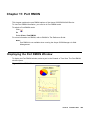
Displaying the Port RMON Window . . .
The Pie Chart. . . . . . . . . . . . . .
The Traffic Graph . . . . . . . . . . .
Viewing Traffic Statistics . . . . .
Zooming In and Out of the Graph.
Scrolling within the Graph . . . .
Unfreezing the Graph . . . . . . .
Traffic Types . . . . . . . . . . . . . .
.
.
.
.
.
.
.
.
.
.
.
.
.
.
.
.
.
.
.
.
.
.
.
.
.
.
.
.
.
.
.
.
.
.
.
.
.
.
.
.
.
.
.
.
.
.
.
.
.
.
.
.
.
.
.
.
.
.
.
.
.
.
.
.
.
.
.
.
.
.
.
.
.
.
.
.
.
.
.
.
.
.
.
.
.
.
.
.
.
.
.
.
.
.
.
.
.
.
.
.
.
193
Overview of Port Redundancy . . . . . . . . . . . . . . . . . . . . . . . . . . . .
193
Configuring Port Redundancy . . . . . . . . . . . . . . . . . . . . . . . . . . . .
194
Adding a Port Redundancy . . . . . . . . . . . . . . . . . . . . . . . . . . . . . .
195
Port Redundancy Wizard . . . . . . . . . . . . . . . . . .
Port Redundancy Wizard - Welcome . . . . . . . . . .
Port Redundancy Wizard - Primary Port Selection . .
Port Redundancy Wizard - Secondary Port Selection.
Port Redundancy Wizard - Name and Type . . . . . .
Port Redundancy Wizard - Confirmation . . . . . . . .
.
.
.
.
.
.
196
197
198
199
200
201
Deleting Port Redundancies . . . . . . . . . . . . . . . . . . . . . . . . . . . . .
202
Updating the Device . . . . . . . . . . . . . . . . . . . . . . . . . . . . . . . . . .
202
.
.
.
.
.
.
.
.
.
.
.
.
.
.
.
.
.
.
.
.
.
Chapter 13: Port Redundancy . . . . . . . . . . . . . . . . . . . . . . .
.
.
.
.
.
.
.
.
.
.
.
.
.
.
.
.
.
.
.
.
.
189
191
.
.
.
.
.
.
.
.
.
.
.
.
.
.
.
.
.
.
.
.
.
Viewing the Switch Connected Addresses Window. . . . . . . . . . . . . . . . .
Sorting the List of Stations . . . . . . . . . . . . . . . . . . . . . . . . . . . .
.
.
.
.
.
.
.
.
.
.
.
.
.
.
.
.
.
.
.
.
.
189
.
.
.
.
.
.
.
.
.
.
.
.
.
.
.
.
.
.
.
.
.
Switch Connected Addresses Overview . . . . . . . . . . . . . . . . . . . . . . .
.
.
.
.
.
.
.
.
.
.
.
.
.
.
.
.
.
.
.
.
.
189
.
.
.
.
.
.
.
.
.
.
.
.
.
.
.
.
.
.
.
.
.
Chapter 12: Switch Connected Addresses . . . . . . . . . . . . . . . .
.
.
.
.
.
.
.
.
.
.
.
.
.
.
.
.
.
.
.
.
.
185
186
186
186
186
187
187
187
.
.
.
.
.
.
.
.
.
.
.
.
.
.
.
.
.
.
.
.
.
.
.
.
.
.
.
.
.
.
.
.
.
.
.
.
.
.
.
.
.
.
.
.
.
.
.
.
.
.
.
.
.
.
.
.
.
.
.
.
.
.
.
.
.
.
.
.
.
.
Issue 5 October 2007
7
Contents
Chapter 14: Trap Managers Configuration. . . . . . . . . . . . . . . . .
203
Trap Manager Overview . . . . . . . . . . . . . . . . . . . . . . . . . . . . . . . .
203
Configuring Trap Managers . . . . . . . . . . . . . . . . . . . . . . . . . . . . . .
204
Editing the Trap Managers Table . . . . . . . . . . . . . . . . . . . . . . . . . . .
206
Chapter 15: Routing Manager . . . . . . . . . . . . . . . . . . . . . . .
207
TheRouting Manager User Interface
Toolbar . . . . . . . . . . . . . .
Tree View . . . . . . . . . . . . .
Table/Form Area . . . . . . . . .
.
.
.
.
.
.
.
.
.
.
.
.
.
.
.
.
.
.
.
.
.
.
.
.
.
.
.
.
.
.
.
.
.
.
.
.
.
.
.
.
.
.
.
.
.
.
.
.
.
.
.
.
.
.
.
.
.
.
.
.
.
.
.
.
.
.
.
.
.
.
.
.
.
.
.
.
.
.
.
.
.
.
.
.
.
.
.
.
.
.
.
.
.
.
.
.
.
.
.
.
207
208
209
210
Editing Tables . . . . . . . . . . . .
Creating New Table Entries .
Modifying Table Entries . . .
Deleting Table Entries . . . .
.
.
.
.
.
.
.
.
.
.
.
.
.
.
.
.
.
.
.
.
.
.
.
.
.
.
.
.
.
.
.
.
.
.
.
.
.
.
.
.
.
.
.
.
.
.
.
.
.
.
.
.
.
.
.
.
.
.
.
.
.
.
.
.
.
.
.
.
.
.
.
.
.
.
.
.
.
.
.
.
.
.
.
.
.
.
.
.
.
.
.
.
.
.
.
.
.
.
.
.
210
211
211
211
Saving Table Information in a File . . . . . . . . . . . . . . . . . . . . . . . . . .
211
Saving Configuration Changes . . . . . . . . . . . . . . . . . . . . . . . . . . . .
Running Changes . . . . . . . . . . . . . . . . . . . . . . . . . . . . . . . . .
Committed Changes . . . . . . . . . . . . . . . . . . . . . . . . . . . . . . . .
212
212
212
Resetting a Router . . . . . . . . . . . . . . . . . . . . . . . . . . . . . . . . . . .
212
Using Avaya G250/G350/G450 Routing Manager Help . . . . . . . . . . . . . . .
Opening the Help to the Contents Page . . . . . . . . . . . . . . . . . . . . .
Opening the Help to a Topic of Interest . . . . . . . . . . . . . . . . . . . . .
213
213
213
Chapter 16: Layer 2 . . . . . . . . . . . . . . . . . . . . . . . . . . . . .
215
Layer 2 Interfaces . . . . . . . . . . . . . . . . . . . . . . . . . . . . . . . . . . .
215
Chapter 17: IP Route . . . . . . . . . . . . . . . . . . . . . . . . . . . .
217
Displaying IP Global Parameters . . . . . . . . . . . . . . . . . . . . . . . . . . .
218
Configuring IP Interfaces . . . . . . . . . . . . . . . . . . . . . . . . . . . . . . .
219
Viewing the Dynamic IP Interfaces Table . . . . . . . . . . . . . . . . . . . . . .
222
Viewing the Routing Table . . . . . . . . . . . . . . . . . . . . . . . . . . . . . .
223
Viewing the Static Routing Table . . . . . . . . . . . . . . . . . . . . . . . . . . .
226
Viewing the ARP Table . . . . . . . . . . . . . . . . . . . . . . . . . . . . . . . .
228
Configuring GRE Tunneling. . . . . . . . . . . . . . . . . . . . . . . . . . . . . .
230
DHCP . . . . . . . . . . . . . . . . . . . . . . . . . . . . . . . . . . . . . . . . . .
Viewing DHCP/BOOTP Global Parameters. . . . . . . . . . . . . . . . . . . .
Configuring DHCP/BOOTP Parameters . . . . . . . . . . . . . . . . . . . . .
233
233
234
RIP . . . . . . . . . . . . . . . . . . . . . . . . . . . . . . . . . . . . . . . . . . .
235
8 Avaya Integrated Management Release 4.0.1 Software Update Manager
Contents
Viewing RIP Global Parameters. . . . . . . . . . . . . . . . . . . . . . . . . .
Configuring RIP Interfaces . . . . . . . . . . . . . . . . . . . . . . . . . . . .
OSPF . . . . . . . . . . . . . . . . . . . . .
Viewing OSPF Global Parameters . . .
Configuring OSPF Interfaces . . . . . .
Configuring OSPF Area Parameters . .
Viewing the OSPF Link State Database
Viewing the OSPF External Database .
Viewing OSPF Neighbors . . . . . . . .
.
.
.
.
.
.
.
.
.
.
.
.
.
.
.
.
.
.
.
.
.
.
.
.
.
.
.
.
.
.
.
.
.
.
.
238
239
240
242
243
245
246
VRRP . . . . . . . . . . . . . . . . . . . . . . . . . . . . . . . . . . . . . . . . . .
Viewing VRRP Global Parameters . . . . . . . . . . . . . . . . . . . . . . . .
Viewing the VRRP Table. . . . . . . . . . . . . . . . . . . . . . . . . . . . . .
247
247
248
Header Compression . . . . . . . . . . . . . . . . . . . . . . . . . . . . . . . . .
Configuring cRTP Interfaces . . . . . . . . . . . . . . . . . . . . . . . . . . .
Configuring TCP Header Compression Interfaces . . . . . . . . . . . . . . .
250
250
251
Chapter 18: Policy Based Routing Manager . . . . . . . . . . . . . . . .
253
The Policy Based Routing Manager User Interface
Toolbar . . . . . . . . . . . . . . . . . . . . . .
Tree View . . . . . . . . . . . . . . . . . . . . .
Table View . . . . . . . . . . . . . . . . . . . .
.
.
.
.
.
.
.
Using the Table View . . . . . . . .
Policy Based Routing List. . . .
Adding Policies . . . . . . .
Deleting Policies . . . . . . .
Policy Based Routing Rules List
Adding Rules . . . . . . . . .
Modifying Rules . . . . . . .
258
259
260
260
260
264
264
.
.
.
.
.
.
.
.
.
.
.
.
.
.
.
.
.
.
.
.
.
.
.
.
.
.
.
.
.
.
.
.
.
.
.
.
.
.
.
.
.
.
.
.
.
.
.
.
.
.
.
.
.
.
.
.
.
.
.
.
.
.
.
.
.
.
.
258
.
.
.
.
.
.
.
.
.
.
.
.
.
.
.
.
.
.
Using the Tree View . . . . . . . . . . . . . . . . . . . . . . . . . . . . . . . . . .
.
.
.
.
.
.
.
.
.
.
.
.
.
.
.
.
.
.
257
.
.
.
.
.
.
.
.
.
.
.
.
.
.
.
.
.
.
Policy Based Routing Overview . . . . . . . . . . . . . . . . . . . . . . . . . . .
.
.
.
.
.
.
.
.
.
.
.
.
.
.
.
.
.
.
257
.
.
.
.
.
.
.
.
.
.
.
.
.
.
.
.
.
.
Chapter 19: Policy Based Routing . . . . . . . . . . . . . . . . . . . . .
.
.
.
.
.
.
.
.
.
.
.
.
.
.
.
.
.
.
256
256
256
.
.
.
.
.
.
.
.
.
.
.
.
.
.
.
.
.
.
Using Avaya G250/G350/G450 Policy Based Routing Manager Help. . . . . . . .
Opening the Help to the Contents Page . . . . . . . . . . . . . . . . . . . . .
Opening the Help to a Topic of Interest . . . . . . . . . . . . . . . . . . . . .
.
.
.
.
.
.
.
.
.
.
.
.
.
.
.
.
.
.
255
256
256
.
.
.
.
.
.
.
.
.
.
.
.
.
.
.
.
.
.
Saving Configuration Changes . . . . . . . . . . . . . . . . . . . . . . . . . . . .
Applied Changes. . . . . . . . . . . . . . . . . . . . . . . . . . . . . . . . . .
Committed Changes . . . . . . . . . . . . . . . . . . . . . . . . . . . . . . . .
.
.
.
.
.
.
.
.
.
.
.
.
.
.
.
.
.
.
255
.
.
.
.
.
.
.
.
.
.
.
.
.
.
.
.
.
.
The Application Editor Tool . . . . . . . . . . . . . . . . . . . . . . . . . . . . . .
.
.
.
.
.
.
.
.
.
.
.
.
.
.
.
.
.
.
253
254
255
255
.
.
.
.
.
.
.
.
.
.
.
.
.
.
.
.
.
.
.
.
.
.
.
.
.
.
.
.
.
.
.
.
.
.
.
.
.
.
.
.
235
236
.
.
.
.
.
.
.
.
.
.
.
.
.
.
.
.
.
.
.
.
.
.
.
.
.
Issue 5 October 2007
9
Contents
Copying Rules . . . . . . . . . . . . . . .
Moving Rules. . . . . . . . . . . . . . . .
Deleting Rules . . . . . . . . . . . . . . .
Next Hop List. . . . . . . . . . . . . . . . . .
Adding Routes . . . . . . . . . . . . . . .
Modifying Routes . . . . . . . . . . . . .
Copying Routes . . . . . . . . . . . . . .
Moving Routes . . . . . . . . . . . . . . .
Deleting Routes . . . . . . . . . . . . . .
Policy Enforcement Points . . . . . . . . . .
Configuration . . . . . . . . . . . . . . . . .
Policy Based Routing List Configuration
Next Hop List Configuration . . . . . . .
.
.
.
.
.
.
.
.
.
.
.
.
.
264
265
265
265
266
267
267
267
268
268
269
269
271
Using Address Wildcards . . . . . . . . . . . . . . . . . . . . . . . . . . . . . . .
272
Using the IP Simulate Function . . . . . . . . . . . . . . . . . . . . . . . . . . . .
IP Simulate Overview . . . . . . . . . . . . . . . . . . . . . . . . . . . . . . .
Using IP Simulate . . . . . . . . . . . . . . . . . . . . . . . . . . . . . . . . .
272
272
273
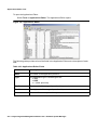
Chapter 20: Applications Editor Tool . . . . . . . . . . . . . . . . . . .
277
Applications Editor Overview . . . . . . . . . . . . . . . . . . . . . . . . . . . . .
277
Using the Applications Editor. . . . .
Adding Application Protocols . .
Modifying an Application Protocol
Deleting an Application Protocol .
Applying Changes . . . . . . . . .
.
.
.
.
.
277
279
279
279
279
Reports . . . . . . . . . . . . . . . . . . . . . . . . . . . . . . . . . . . . . . . . .
280
Appendix A: Menus . . . . . . . . . . . . . . . . . . . . . . . . . . . . .
281
Device Manager Menus
File Menu . . . . . .
View Menu . . . . .
Configure Menu . .
Actions Menu . . .
Tools Menu . . . . .
Help Menu . . . . .
.
.
.
.
.
.
.
.
.
.
.
.
.
.
.
.
.
.
.
.
.
.
.
.
.
.
.
.
.
.
.
.
.
.
.
.
.
.
.
.
.
.
.
.
.
.
.
.
.
.
.
.
.
.
.
.
.
.
.
.
.
.
.
.
.
.
.
.
.
.
.
.
.
.
.
.
.
.
.
.
.
.
.
.
.
.
.
.
.
.
.
.
.
.
.
.
.
.
.
.
.
.
.
.
.
.
.
.
.
.
.
.
.
.
.
.
.
.
.
.
.
.
.
.
.
.
.
.
.
.
.
.
.
.
.
.
.
.
.
.
.
.
.
.
.
.
.
.
.
.
.
.
.
.
.
.
.
.
.
.
.
.
.
.
.
.
.
.
.
.
.
.
.
.
.
.
.
.
.
.
.
.
.
.
.
.
.
.
.
.
.
.
.
.
.
.
.
.
.
.
.
.
.
.
.
.
.
.
.
.
.
.
.
.
.
.
.
.
.
.
.
.
.
.
.
.
.
.
.
.
.
.
.
.
.
.
.
.
.
.
.
.
.
.
.
.
.
.
.
.
.
.
.
.
.
.
.
.
.
.
.
.
.
.
.
.
.
.
.
.
.
.
.
.
.
.
.
.
.
.
.
.
.
.
.
.
.
.
.
.
.
.
.
.
.
.
.
.
.
.
.
.
.
.
.
.
.
.
.
.
.
.
.
.
.
.
.
.
.
.
.
.
.
.
.
.
.
.
.
.
.
.
.
.
.
.
.
.
.
.
.
.
.
.
.
.
.
.
.
.
.
.
.
.
.
.
.
.
.
.
.
.
.
.
.
.
.
.
.
.
.
.
.
.
.
.
.
.
.
.
.
.
.
.
.
.
.
.
.
.
.
.
.
.
.
.
.
.
.
.
.
.
.
.
.
.
.
.
.
.
.
.
.
.
.
.
.
.
.
.
.
.
.
.
.
.
.
.
.
.
.
.
.
.
.
.
.
.
.
.
.
.
.
.
.
.
.
.
.
.
.
.
.
.
.
.
.
.
.
.
.
.
.
.
.
.
.
.
.
.
.
.
.
.
.
.
.
.
.
.
.
.
.
.
.
.
.
.
.
.
.
.
.
.
.
.
.
.
.
.
.
.
.
.
.
.
.
.
.
.
.
.
.
.
.
.
.
.
.
.
.
.
.
.
.
.
.
.
.
.
.
.
.
.
.
.
.
.
.
.
.
.
.
.
.
.
.
.
.
.
.
.
.
.
.
.
.
.
.
.
281
282
282
282
284
284
285
Routing Manager Menus
File Menu . . . . . . .
Edit Menu. . . . . . .
View Menu . . . . . .
Action Menu . . . . .
.
.
.
.
.
.
.
.
.
.
.
.
.
.
.
.
.
.
.
.
.
.
.
.
.
.
.
.
.
.
.
.
.
.
.
.
.
.
.
.
.
.
.
.
.
.
.
.
.
.
.
.
.
.
.
.
.
.
.
.
.
.
.
.
.
.
.
.
.
.
.
.
.
.
.
.
.
.
.
.
.
.
.
.
.
.
.
.
.
.
.
.
.
.
.
.
.
.
.
.
.
.
.
.
.
.
.
.
.
.
.
.
.
.
.
.
.
.
.
.
.
.
.
.
.
.
.
.
.
.
.
.
.
.
.
.
.
.
.
.
.
.
.
.
.
.
.
.
.
.
.
.
.
.
.
285
285
286
286
286
10 Avaya Integrated Management Release 4.0.1 Software Update Manager
Contents
Help Menu . . . . . . . . . . . . . . . . . . . . . . . . . . . . . . . . . . . . .
287
Policy Based Routing Menus .
File Menu . . . . . . . . . .
Edit Menu. . . . . . . . . .
View Menu . . . . . . . . .
Tools Menu . . . . . . . . .
Help Menu . . . . . . . . .
.
.
.
.
.
.
.
.
.
.
.
.
.
.
.
.
.
.
.
.
.
.
.
.
.
.
.
.
.
.
.
.
.
.
.
.
.
.
.
.
.
.
.
.
.
.
.
.
.
.
.
.
.
.
.
.
.
.
.
.
.
.
.
.
.
.
.
.
.
.
.
.
.
.
.
.
.
.
.
.
.
.
.
.
.
.
.
.
.
.
.
.
.
.
.
.
.
.
.
.
.
.
.
.
.
.
.
.
.
.
.
.
.
.
.
.
.
.
.
.
.
.
.
.
.
.
.
.
.
.
.
.
.
.
.
.
.
.
.
.
.
.
.
.
.
.
.
.
.
.
.
.
.
.
.
.
.
.
.
.
.
.
.
.
.
.
.
.
287
287
288
288
288
289
Applications Editor Menus
File Menu . . . . . . . .
Edit Menu. . . . . . . .
Help Menu . . . . . . .
.
.
.
.
.
.
.
.
.
.
.
.
.
.
.
.
.
.
.
.
.
.
.
.
.
.
.
.
.
.
.
.
.
.
.
.
.
.
.
.
.
.
.
.
.
.
.
.
.
.
.
.
.
.
.
.
.
.
.
.
.
.
.
.
.
.
.
.
.
.
.
.
.
.
.
.
.
.
.
.
.
.
.
.
.
.
.
.
.
.
.
.
.
.
.
.
.
.
.
.
.
.
.
.
.
.
.
.
.
.
.
.
289
289
290
290
Appendix B: Web Management. . . . . . . . . . . . . . . . . . . . . . .
291
Web Management Overview . . . . . . . . . . . . . . . . . . . . . . . . . . . . .
291
Configuring the Avaya G350/G450 Device . . . . . . . . . . . . . . . . . . . . . .
291
Appendix C: ICMP Packet Types & Codes . . . . . . . . . . . . . . . . .
293
ICMP Packet Type/Code List . . . . . . . . . . . . . . . . . . . . . . . . . . . . .
293
Index
.
.
.
.
.
.
.
.
. . . . . . . . . . . . . . . . . . . . . . . . . . . . . . . . . .
297
Issue 5 October 2007
11
Contents
12 Avaya Integrated Management Release 4.0.1 Software Update Manager
Preface
Welcome to Avaya G250/G350/G450 Manager. This chapter provides an introduction to the
structure and assumptions of this guide. It includes the following sections:
●
The Purpose of This Guide - A description of the goals of this guide.
●
Who Should Use This Guide - The intended audience of this guide.
●
Organization of This Guide - A brief description of the subjects contained in the various
sections of this guide.
The Purpose of This Guide
The Avaya G250/G350/G450 Manager guide contains information needed to use the
management system efficiently and effectively.
Who Should Use This Guide
This guide is intended for network managers familiar with network management and its
fundamental concepts.
Organization of This Guide
This guide is structured to reflect the following conceptual divisions
●
●
Avaya G250/G350/G450 Manager - Information pertaining to the entire Avaya G250/
G350/G450 Manager application and all of its aspects.
●
Preface - This section describes the guide’s purpose, intended audience and
organization.
●
Introduction - An introduction to the Avaya G250/G350/G450 Manager, including
instructions on starting the Avaya G250/G350/G450 Manager.
Avaya G250/G350/G450 Device Manager - Information pertaining to Avaya G250/G350/
G450 Device Management.
Issue 5 October 2007
13
Preface
●
●
●
Device Manager - An introduction to the Avaya G250/G350/G450 Device Manager,
including a description of the user interface.
●
Device Configuration - Viewing and modifying the different device configurations.
●
Power over Ethernet - An overview of Power over Ethernet (PoE) and instructions on
viewing and configuring PoE parameters.
●
Media Gateway Functions - An overview of the Media Gateway functions and
information on viewing and configuring Media Gateway components.
●
VoIP Engine Configuration - An overview of VoIP Engine functionality and information
on viewing and configuring VoIP Engine parameters.
●
WAN Configuration - An overview of and information on viewing and configuring WAN
parameters.
●
Embedded Tools - An overview of and information on configuring the Avaya G250/
G350/G450’s embedded server functions and tools.
●
VLANs - Viewing and editing VLAN information.
●
Port Mirroring - Configuring port mirroring for ports on an Avaya G250/G350/G450
device.
●
Port RMON - Viewing graphical representations of the traffic on the ports of the Avaya
G250/G350/G450 device.
●
Port Redundancy - Configuring port redundancy for ports on an Avaya G350 or
G450device.
●
Switch-Connected Addresses - Viewing information on addresses connected to the
device.
●
Trap Managers Configuration - Viewing and modifying the Trap Managers table.
Avaya G250/G350/G450 Routing Manager - Information pertaining to Avaya G250/G350/
G450 routing management.
●
Routing Manager - An introduction to configuring routing and a description of the
Avaya G250/G350/G450 Routing Manager user interface.
●
Layer 2 - Detailed descriptions of layer 2 configuration that enable you to view layer 2
interfaces at the management station.
●
IP Route - Detailed descriptions of IP route configuration that enable you to display and
update IP interfaces, the IP routing table, the ARP table, GRE tunneling parameters,
DHCP/BOOTP parameters, RIP interfaces, OSPF interfaces, area parameters, link-state
database and neighbors, the IP access control table, and redundancy parameters.
Avaya G250/G350/G450 Policy Based Routing Manager - Information pertaining to
Avaya G250/G350/G450 Policy Based Routing management.
●
Policy Based Routing Manager - An introduction to configuring Policy Based Routing
and a description of the Avaya G250/G350/G450 Policy Based Routing Manager user
interface.
14 Avaya Integrated Management Release 4.0.1 Software Update Manager
Organization of This Guide
●
●
Policy Based Routing - Detailed descriptions of Policy Based Routing configuration that
enable you to display and update Policy Based Routing lists, Next Hop routing tables,
and Policy Enforcement Points.
●
Applications Editor Tool - Detailed description of the Applications Editor Tool, which
enables you to refine protocol traffic through Policy Based Routing by customizing
individual protocols.
Appendices - Additional information about the Avaya G250/G350/G450 Manager.
●
Menus - The full structure of the menus in the Avaya G250/G350/G450 Manager.
●
Web Management - Instructions on how to manage Avaya G350 and G450 devices via
the Internet.
●
ICMP Packet Types and Codes - A list of ICMP Packet Types and Codes as used in IP
SImulate.
Issue 5 October 2007
15
Preface
16 Avaya Integrated Management Release 4.0.1 Software Update Manager
Chapter 1: Introduction
This chapter provides an introduction to the Avaya G250/G350/G450 Manager. It includes the
following sections:
●
Avaya G250/G350/G450 Manager Overview - An overview explaining the different aspects
of Avaya G250/G350/G450 Device management.
●
Starting the Avaya G250/G350/G450 Manager - Instructions on how to access
Avaya G250/G350/G450 Manager from your management platform.
●
The User Interface - Detailed descriptions of the user interface common to all applications
in the Avaya G250/G350/G450 Manager.
●
Managing Tables - An explanation of the symbols used to label table rows.
Avaya G250/G350/G450 Manager Overview
The Avaya G250/G350/G450 Manager provides full management capabilities for Avaya G450,
Avaya G350, and all G250 Devices. This includes the ability to view three aspects of device
management:
●
Device Manager - Provides a view of the configuration of the device, including VLAN
configuration, port redundancy, port mirroring, switch connected addresses and traps. For
more information refer to chapters 2-14.
●
Routing Manager - Provides a view of the Layer 3 routing and forwarding functions of the
device. For more information refer to chapters 15-17.
●
Policy Based Routing Manager - Provides a view of the configuration and maintenance
of Policy Based Routing on the Avaya G250/G350/G450 device. For information, refer to
chapters 18-19.
For information on switching between the different views, refer to “Application Tabs” on page 20.
Issue 5 October 2007
17
Introduction
Starting the Avaya G250/G350/G450 Manager
This section provides instructions for starting Avaya G250/G350/G450 Manager.
Avaya G250/G350/G450 Device Manager as Part of Avaya Network
Management
If you installed the Avaya G250/G350/G450 Device Manager as part of Avaya Network
Management, the following sections provide instructions for starting Avaya G250/G350/G450
Manager.
Running Avaya G250/G350/G450 Manager from Avaya Network
Management Console
From the management platform map:
1. Select the label representing the Avaya G250/G350/G450 Device you want to manage.
2. Click
.
Or
Double-click the Avaya G250/G350/G450 Device.
Or
Select Tools > Avaya Device Manager.
Avaya G350/G450 Manager via Web Management
Note:
Note:
The Avaya G250 Device does not support web management.
To start Avaya G350/G450 Web Management:
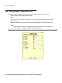
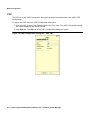
1. Point your web browser to http://xxx.xxx.xxx.xxx, where xxx.xxx.xxx.xxx is the
IP address of the Avaya G350/G450 Device you want to manage. The Enter Network
Password dialog box opens.
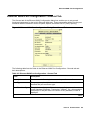
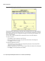
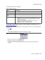
18 Avaya Integrated Management Release 4.0.1 Software Update Manager
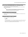
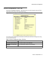
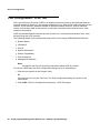
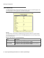
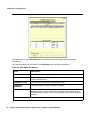
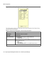
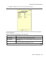
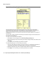
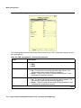
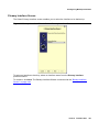
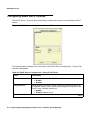
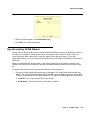
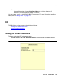
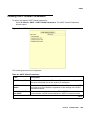
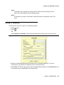
The User Interface
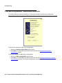
Figure 1: Enter Network Password Dialog Box
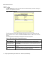
2. Select the desired SNMP mode of operation.
If SNMPv1 is selected, enter the correct SNMPv1 community string in the Community field.
Or
If SNMPv3 is selected, enter a valid username from the SNMPv3 username list and
corresponding authentication and privacy passwords.
Note:
Some operations in the Avaya G250/G350/G450 Manager require SNMPv3
authentication credentials. Verify that you are an SNMPv3 user or use the SAA
application. You can use the CLI to create users on the media gateway.
Note:
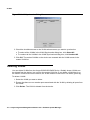
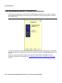
3. Click OK. The Avaya G350/G450 Welcome page opens.
If the required Java plug-in is installed on your computer, the Java Plug-in Security Warning
dialog box opens after a few seconds.
If the required Java plug-in is not installed, the plug-in is automatically downloaded to your
computer. Follow the instructions on the Avaya G350/G450 Welcome page to install the
plug-in.
The User Interface
The Avaya G250/G350/G450 Manager user interface is different for each of its management
applications. However, the following elements of the user interface are common to all views:
●
Application Tabs - Tabs for accessing the Device Manager, Policy Based Routing
Manager, and Routing Manager applications for the Avaya G250/G350/G450 Device.
●
Application Area - An area where the selected application opens.
●
Status Line - Displays the communication status between the Avaya G250/G350/G450
Manager and the Avaya G250/G350/G450 Device.
Issue 5 October 2007
19
Introduction
Application Tabs
You can access the three main components of device management using the following
Application Tabs in the Avaya G250/G350/G450 Manager:
●
Device Manager - View the Avaya G250/G350/G450 Device Manager for device
configuration and Port RMON.
●
Policy Based Routing Manager - View the Policy Based Routing and Next Hop Routing
configuration for the device.
●
Routing Manager - View the Avaya G250/G350/G450 Routing configuration.
To switch to a different view, click the appropriate Application Tab. The selected application
opens.
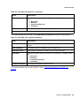
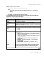
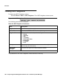
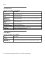
Status Line
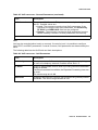
The Status Line shows the communication status between the application and the Avaya G250/
G350/G450 Device. The Status Line displays a status message and an appropriate graphic.
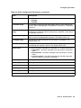
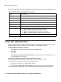
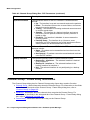
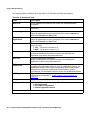
The table below shows the possible statuses with their corresponding graphics, and provides an
explanation for each status.
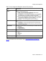
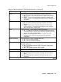
Table 1: Communication Statuses
Status
Graphic
Description
Ready
The application is ready to communicate
with the Avaya G250/G350/G450 Device.
Communicating
The application is currently communicating
with the Avaya G250/G350/G450 Device.
Communication Error
The last attempted communication with the
Avaya G250/G350/G450 Device was not
successful.
20 Avaya Integrated Management Release 4.0.1 Software Update Manager
Managing Tables
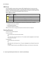
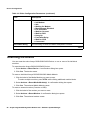
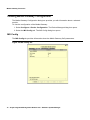
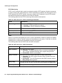
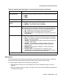
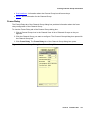
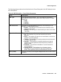
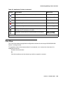
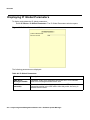
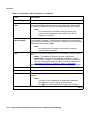
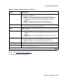
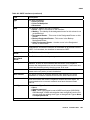
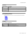
Managing Tables
The Avaya G250/G350/G450 Manager interface displays the status of each row in a table. The
following table shows a list of symbols that can appear at the start of a table row, with their
corresponding explanations.
Table 2: Table Symbols
Symbol
Explanation
The row is a new entry.
The row is to be deleted.
The information in the row has been changed by the
user.
To undo all the changes made to a table, click Refresh. To undo changes made to a selected
row, click Undo. When all changes are finalized, click Apply to update the device.
Issue 5 October 2007
21
Introduction
22 Avaya Integrated Management Release 4.0.1 Software Update Manager
Chapter 2: Device Manager
This chapter provides an introduction to the Avaya G250/G350/G450 Device Manager. It
includes the following sections:
●
The G250/G350/G450 Device Manager User Interface - An introduction to the Avaya
G250/G350/G450 Device Manager user interface, including instructions for selecting
elements and using the toolbar buttons.
●
Avaya G250/G350/G450 Modes - Instructions on switching between the configuration and
Port RMON modes in the Avaya G250/G350/G450 Device Manager.
●
Refreshing Device Information - Instructions on how to refresh the information in the Avaya
G250/G350/G450 Manager.
●
Using Dialog Boxes and Tables - An explanation of the icons found in the dialog boxes and
tables in the Avaya G250/G350/G450 Device Manager.
●
Using Avaya G250/G350/G450 Device Manager Help - An explanation of the options for
accessing on-line help in the Avaya G250/G350/G450 Device Manager.
The G250/G350/G450 Device Manager User Interface
The Avaya G250/G350/G450 Device Manager user interface consists of the following elements:
●
Application Tabs - Tabs for toggling between Avaya G250/G350/G450 Manager functions
(Device Manager, Routing Manager, Policy-Based Routing Manager).
●
Menu Bar - Menus for accessing Avaya G250/G350/G450 Device management functions.
For more information, refer to Appendix A: Menus.
●
Application Toolbar - Toolbar buttons for accessing Avaya G250/G350/G450 Device
management functions.
●
Get/Set Toolbar - Toolbar buttons for viewing and changing the configuration of ports.
●
Tree View - A resizeable window containing a hierarchical representation of the modules
and ports of the Avaya G250/G350/G450 Device.
●
Chassis View - A graphical representation of the Avaya G250/G350/G450 Device.
●
Dialog Area - A resizeable window where all dialog boxes and tables first open.
For information on other parts of the user interface, refer to “The User Interface” on page 19.
Issue 5 October 2007
23
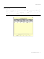
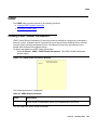
Device Manager
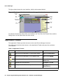
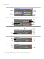
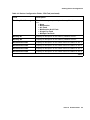
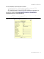
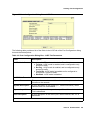
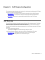
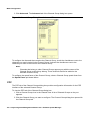
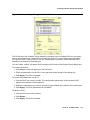
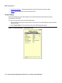
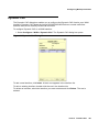
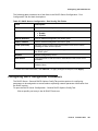
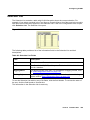
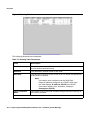
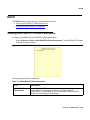
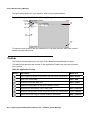
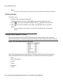
The figure below shows the user interface, with its various parts labeled.
Figure 2: The Avaya G250/G350/G450 Device Manager User Interface
Application
Tabs
Get/Set
Toolbar
Menu
Bar
Chassis
View
Application
Toolbar
Dialog
Area
Tree
View
Status
Line
To resize the three main areas of the user interface, the Tree View, the Chassis View, and the
Dialog Area, use the splitter bars and their arrows.
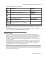
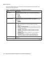
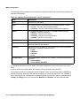
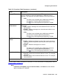
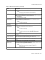
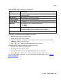
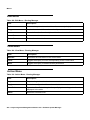
Application Toolbar
The Application Toolbar provides shortcuts to the main Device Manager functions.
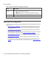
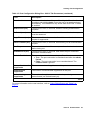
The table below describes the buttons on the Application Toolbar and gives the equivalent
menu options.
Table 3: Application Toolbar
Button
Description
Menu Item
Sets the Device Manager to Configuration Mode.
View > Configuration
Sets the Device Manager to Port RMON mode.
View > Port RMON
Shows Switch-Connected Addresses.
View > Switch-Connected
Addresses
Displays the VLAN window.
Configure > VLAN
Displays the Port Redundancy table.
Configure > Port
Redundancy
1 of 2
24 Avaya Integrated Management Release 4.0.1 Software Update Manager
The G250/G350/G450 Device Manager User Interface
Table 3: Application Toolbar (continued)
Button
Description
Menu Item
Starts the Port Mirroring wizard.
Configure > Port
Mirroring
Displays the Trap Manager Table.
Configure > Trap
Managers
Commits configuration changes.
Actions > Commit
Launches Avaya Call Processing on the selected
Media Gateway or Voice port.
Tools > Administer
Station/Gateway
Opens the on-line help.
Help > Help On
Selects a VLAN. Ports that are not on the selected
VLAN appear dark gray in the Chassis View.
2 of 2
When you place the cursor on a toolbar icon for one second, a label appears with the name of
the button.
You can toggle the display of the application toolbar. To toggle the display of the application
toolbar, select View > Toolbars > Show Application Toolbar.
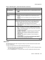
Get/Set Toolbar
The Get/Set Toolbar provides buttons for getting and setting configuration parameters for
selected ports. When a port is selected, its configuration is reflected on the Get/Set Toolbar.
Each group of buttons represents the various possible states of a configuration parameter. For
example, the first group of buttons represents the possible speed of a port - 10 Mbps,
100 Mbps, or 1000 Mbps. If the center button is depressed, the port is currently configured to
operate at 100 Mbps.
Selected ports can be configured using the Get/Set Toolbar. To change the configuration of a
port, click the button that represents the value of the parameter you want to apply to the port.
Click apply to update the device with the changes. Click cancel to discard the changes.
Options not applicable to the selected port are greyed out.
Multiple ports can be simultaneously configured using the Get/Set Toolbar. When multiple ports
with non-identical configurations are selected, only the parameters whose settings are identical
on the selected ports are reflected in the Get/Set Toolbar. For example, if a port operating at full
duplex and a port operating at half duplex are selected, neither of the duplex mode buttons on
the Get/Set Toolbar are depressed.
Issue 5 October 2007
25
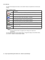
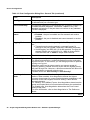
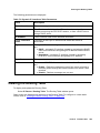
Device Manager
The table below displays the buttons on the Get/Set Toolbar and explains their functions and
settings.
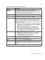
Table 4: Get/Set Toolbar
Button
Description
Get and set the port’s speed: 10 Mbps, 100 Mbps, 1000 Mbps.
Get and set the port’s status: Enabled, Disabled.
Get and set the port’s mode: Half duplex, Full duplex.
Get and set the port’s auto-negotiation status:
Auto-negotiation Enabled, Auto-negotiation Disabled.
Get and set the port’s STP mode: Enabled, Disabled.
Get and set the port’s Power over Ethernet (not relevant for G450).
Get and set the port’s priority. Select a priority level between 1 and 8 using
the pull-down listbox.
Apply or cancel the configuration changes made with the Get/Set Toolbar.
Note:
Note:
The Apply/Cancel buttons only appear when changes are made to the
configuration.
You can toggle the display of the Get/Set toolbar. To toggle the display of the Get/Set toolbar,
select View > Toolbars > Show Get/Set Toolbar.
26 Avaya Integrated Management Release 4.0.1 Software Update Manager
The G250/G350/G450 Device Manager User Interface
Tree View
The Tree View shows a hierarchical representation of the structure of the Avaya G250/G350/
G450 Device. To select ports, modules or media modules, click their icons in the Tree View.
When an element is selected in the Tree View, the corresponding element is selected in the
Chassis View.
The highest level of the Tree View represents the device. The second level shows modules. The
third level shows ports. This includes ports on expansion modules.
To expand the view of a contracted element in the tree or to contract the view of an expanded
element in the tree:
Double-click the element.
Or
Click the handle next to the element you want to expand or contract.
Desktop
The central section of the application window is the Desktop. This area can be resized by
dragging the vertical splitter bars with the mouse. Floating dialog boxes and tables can be
resized. The Chassis View and floating dialog boxes and tables can also be minimized.
Minimized windows appear at the bottom of the Desktop.
Chassis View
The Chassis View is a graphical representation of the Avaya G250/G350/G450 device. The
Avaya G250/G350/G450 device can contain several Avaya G250/G350/G450 modules. The
Chassis View shows all of the devices’ modules and ports. The colors of the modules and ports
in the Chassis View reflect their status.
When you hold the cursor over a port’s icon in the Chassis View, a label appears with the port
number, its VLAN ID, and the last fault that occurred on the port.
Issue 5 October 2007
27
Device Manager
Figure 3: Avaya G450 Chassis View
Figure 4: Avaya G350 Chassis View
Port
Symbols
Power
Symbols
Module
Identifier
Channel
GroupSymbol
FixedPorts
Media
Module
Figure 5: Avaya G250 Chassis View
Media
Module
Channel
Group
Symbol
Module
Identifier
Fixed
Ports
Port
Symbols
Power
Symbols
Figure 6: Avaya G250 - BRI Chassis View
Module
Expansion
Slot
Fixed
Ports
Port
Symbols
Power
Symbols
Figure 7: Avaya G250 - DCP Chassis View
Module
Expansion
Slot
Fixed
Ports
28 Avaya Integrated Management Release 4.0.1 Software Update Manager
Port
Symbols
The G250/G350/G450 Device Manager User Interface
Figure 8: Avaya G250 - DS1 Chassis View
Module
Identifier
Media
Module
Port
Symbols
Fixed
Ports
Power
Symbols
When viewing selected dialog boxes, the color of the port indicates the status of the port with
regard to the application. The port selected to be the base port appears dark blue. The ports
selected to be additional ports appear cyan.
The following table provides a list of the possible port colors in the Chassis View and their
meaning.
Table 5: Chassis View Port Colors
Color
Meaning
Green
The port is enabled, and its status is Okay.
Yellow
The port is enabled, and its status is Warning.
Red
The port is enabled, and its status is Fatal.
Light Gray
The port is disabled.
Dark Gray
The port is not associated with the assignment.
White
The port is logically available for assignment.
Dark Blue
The port has been assigned the primary position in an application.
Cyan
The port has been assigned a secondary position in an application.
Issue 5 October 2007
29
Device Manager
GBIC Ports
The Avaya MM314 media modules contain a GBIC (GigaBit Interface Converter) port that
houses removable transceiver modules. The Chassis View reflects the management status of
this ports. The following table shows the possible appearances of this port in the Chassis View
and provides the corresponding management status of the port.
Table 6: GBIC Port Status
GBIC Port
Status
The GBIC port contains a supported transceiver module.
There is no transceiver module present in the GBIC port.
The transceiver module in the GBIC port is not supported.
The transceiver module in the GBIC port is of an unknown type.
GBIC ports that contain the following types of transceiver modules can be configured:
●
Supported transceiver modules
●
No transceiver modules
●
Unknown transceiver modules
GBIC ports that contain unsupported transceiver modules cannot be configured.
Selecting Elements
You can select modules and ports.
To select a module:
In the Chassis View, click the module’s label.
Or
In the Tree View, click the module’s icon. The module’s label is highlighted in the Chassis
View and the Tree View.
To select a port:
In the Chassis View, click the port.
Or
In the Tree View, click the port’s icon. The port is highlighted in the Chassis View and the
Tree View.
To select multiple elements, press CTRL while clicking on each element to be selected.
30 Avaya Integrated Management Release 4.0.1 Software Update Manager
Avaya G250/G350/G450 Modes
Dialog Area
The area to the right of the Chassis View is where all dialog boxes, tables, and wizards first
appear. This area can be resized by dragging the vertical splitter bar with the mouse. When a
dialog box, table, or wizard opens, it replaces the current dialog box open in the Dialog Area. To
view more than one dialog box or table simultaneously, click the pushpin in the upper
right-hand corner of the dialog box. The dialog box becomes a floating dialog box and moves to
the Desktop.
To restore a dialog box to the Dialog Area, click the toolbar button or icon that opened the dialog
box. The dialog box returns to the Dialog Area.
Avaya G250/G350/G450 Modes
The Avaya G250/G350/G450 Device Manager has two modes:
Note:
●
Configuration mode
●
Port RMON mode
Note:
When the Avaya G250/G350/G450 Manager is installed as a standalone
manager and when running the Avaya G350/G450 Manager via Web
Management, Port SMON is not available.
When in configuration mode, you can view and change the configuration of the Avaya G250/
G350/G450 Device and individual ports. When in Port RMON mode, you can view graphical
representations of the traffic on individual ports.
Issue 5 October 2007
31
Device Manager
To switch to configuration mode:
Click
.
Or
Select View > Configuration.
To switch to Port RMON mode:
Click
.
Or
Select View > Port RMON.
Refreshing Device Information
You can refresh the information in the Avaya G250/G350/G450 Device Manager. To refresh
Avaya G250/G350/G450 Device information, select View > Refresh. The Avaya G250/G350/
G450 Device Manager refreshes its device information and updates the display.
Using Dialog Boxes and Tables
Dialog boxes and tables in the Avaya G250/G350/G450 Manager application have a common
set of buttons. The following table displays the buttons and explains their functions:
Table 7: Dialog Box Buttons
Button
Function
Refreshes the information in the table or dialog box. This clears any changes
made to the table or dialog box and not yet sent to the device.
Sends the information from the table or dialog box to update the device.
Adds a row to the table.
Deletes the selected rows of the table.
Undoes all changes to the selected row in a table.
32 Avaya Integrated Management Release 4.0.1 Software Update Manager
Using Avaya G250/G350/G450 Device Manager Help
Using Avaya G250/G350/G450 Device Manager Help
This section explains how to use the on-line help in the Avaya
G250/G350/G450 Device Manager. The on-line help can be opened to the contents page or
directly to a topic of interest.
Note:
Note:
When running the Avaya G350/G450 Manager via Web Management, on-line
help is only available if you have installed the on-line help on your network and
configured the device with the location of the help files.
Opening the Help to the Contents Page
To open the help to the contents page, select Help > Contents. The on-line help opens to the
contents page.
Opening the Help to a Topic of Interest
To open the help directly to a topic of interest:
1. Click
.
Or
Select Help > Help On. The cursor changes to the shape of an arrow with a question mark.
2. Click on a point of interest in the Avaya G250/G350/G450 Device Manager. The on-line
help opens to a topic explaining the feature that was clicked.
Issue 5 October 2007
33
Device Manager
34 Avaya Integrated Management Release 4.0.1 Software Update Manager
Chapter 3: Device Configuration
This chapter explains how to view and set the various configuration parameters relevant to the
Avaya G250/G350/G450 Device. It includes the following sections:
●
●
●
●
●
●
Viewing Device Configuration - View high-level information about the Avaya G250/G350/
G450 Device.
Viewing Module Configuration - View information specific to an Avaya G250/G350/G450
module in the device.
Viewing Port Configuration - View information specific to the ports on the Avaya G250/
G350/G450 Device.
Configuring the External Modem - View information specific to an external modem
connected to the Avaya G250/G350/G450 Device.
Configuring the Dialer - View information specific to an external dial-up modem connected
to the Avaya G250/G350/G450 Device.
Resetting the Device - Reset the Avaya G250/G350/G450 Device.
To view configuration information, you must be in Configuration mode. To switch to Configuration
mode:
Click
.
Or
Select View > Configuration.
Viewing Device Configuration
The Device Configuration dialog box provides you with high-level configuration information
specific to the Avaya G250/G350/G450 Device. This information is divided into the following:
●
Device Configuration - General Tab - Provides detailed information about the device such
as the device’s name, addresses, contact person, location, type, description, the number
of modules in the device, and the management VLAN ID.
●
Media Gateway Configuration Tab - Provides detailed information on the configuration
settings of the Media Gateway function of the device. For more information on Media
Gateway Configuration, refer to “Media Gateway Functions” on page 71.
●
Media Gateway Controller Configuration Tab - Provides detailed Quality of Service
statistics for the Media Gateway function of the device. For more information, refer to
“Media Gateway Functions” on page 71.
●
Voice over IP Resources Tab - Provides administration parameters for the VoIP engine.
For more information on VoIP Resources, refer to “VoIP Engine Configuration” on page 77.
●
Voice over IP Status Tab - Provides detailed operating statistics for the VoIP engine. For
more information, refer to “VoIP Engine Configuration” on page 77.
Issue 5 October 2007
35
Device Configuration
Device Configuration - General Tab
To view the General tab of the Device Configuration dialog box:
Select Configure > Device Information. The Device Configuration dialog box opens to the
General tab.
Figure 9: Device Configuration Dialog Box - General Tab
36 Avaya Integrated Management Release 4.0.1 Software Update Manager
Viewing Device Configuration
The following table provides a list of the fields in the General tab of the Device Configuration
dialog box and their descriptions.
Table 8: Device Configuration Fields - General Tab
Field
Description
System Name
Logical name of the device, as defined on the SNMP agent of the
device.
MG Identifier
Identification number of the Media Gateway.
FW version
Firmware release the device is running.
Contact
The individual responsible for the maintenance of this device.
Physical Location
The current physical location of this device.
System Description
A description of the device.
Number Of Modules
The number of Media Modules and expansion modules in the
chassis.
Chassis Serial
Number
The serial number of the chassis (read only) (relevant only for the
Avaya G450 Device).
Chassis
Configuration
Symbol
The configuration symbol of the chassis (read only) (relevant only for
the Avaya G450 Device).
VLAN MAC Address
The MAC address of the VLAN interface.
WAN1 MAC Address
The MAC address of the WAN1 port (relevant only for the
Avaya G450 Device).
WAN2 MAC Address
The MAC address of the WAN2 port (relevant only for the
Avaya G450 Device).
SERVICES MAC
Address
The MAC address of the Services port (relevant only for the
Avaya G450 Device).
Current DS Mode
Speed of serial link. Possible values are:
● T1
● E1
Next DS Mode
Speed of backup serial link, if configured. Possible values are:
● T1
● E1
Current PMI
Interface
Interface currently designated as Primary Management Interface.
1 of 2
Issue 5 October 2007
37
Device Configuration
Table 8: Device Configuration Fields - General Tab (continued)
Field
Description
Current PMI IP
Address
IP address of Primary Management Interface.
Current PMI Subnet
Mask
Subnet mask of Primary Management Interface.
Next PMI Interface
Interface configured by the gateway to be the new Primary
Management Interface. If you set this parameter using the CLI, the
new setting only takes effect after the next device reset.
Next PMI IP Address
IP address configured by the gateway to be the new Primary
Management Interface. If you set this parameter using the CLI, the
new setting only takes effect after the next device reset.
Default Gateway
IP address of the default network gateway device.
ICC VLAN
VLAN of which the device is a member.
Operational Status
The operational status of the device. Possible values are:
● OK - Device is operational.
● Down - Device is reporting faults making it unable to function.
● Fatal - Device is reporting faults that are unrecoverable.
Fault Messages
Number of fault messages reported by the device.
2 of 2
For more information on the user interface, refer to “Using Dialog Boxes and Tables” on
page 32.
38 Avaya Integrated Management Release 4.0.1 Software Update Manager
Viewing Device Configuration
Device Configuration - Advanced Tab
The Device Configuration Dialog Box - Advanced Tab provides you with network bridging
information about the Avaya G250/G350/G450 Device.
Note:
Note:
Avaya G250 Devices do not support the spanning tree protocol, therefore the
STP fields do not appear for an Avaya G250 Device.
Figure 10: Device Configuration Dialog Box - Advanced Tab
The following table provides a list of the fields in the Advanced tab of the Device Configuration
dialog box and their descriptions.
Table 9: Device Configuration Fields - Advanced Tab
Field
Description
STP Mode
Spanning Tree status of the device.
STP Priority
Priority value used in Spanning Tree calculations.
1 of 2
Issue 5 October 2007
39
Device Configuration
Table 9: Device Configuration Fields - Advanced Tab (continued)
Field
Description
STP Version
Version of Spanning Tree on the device. Possible values are:
● STP Compatible - Standard Spanning-Tree Protocol
● RSTP - Rapid Spanning-Tree Protocol
STP Max Age
The maximum amount of time before the Spanning Tree table
recalculates if there is no change in the device status, measured in
milliseconds.
STP Hello Time
The amount of time between sending Spanning Tree updates if
there are no detected changes in the device’s network connections,
measured in milliseconds.
STP Forward Delay
The amount of time for the device to begin forwarding packets when
first joining a network, measured in milliseconds.
STP Bridge Max Age
The maximum amount of time before Spanning recalculates if there
is no change in network bridging status, measured in milliseconds.
STP Bridge Hello
Time
The amount of time between sending Spanning Tree updates if
there are no detected changes in the overall bridged network
topology, measured in milliseconds.
STP Bridge Forward
Delay
The amount of time for the device to begin forwarding packets after
recalculating its Spanning Tree table based on a change in network
topology, measured in milliseconds.
Aging Time (sec)
The amount of time MAC addresses remain in the CAM table.
LLDP Mode
The status of Link Layer Discovery Protocol (LLDP) Mode on the
device:
● Enable - Use LLDP Mode.
● Disable - Do not use LLDP Mode.
LLDP Tx Interval
The amount of time between packet transmissions on the device.
LLDP Tx Hold
Multiplier
The LLDP time-to-live value expressed as a multiple of the value
configured in the LLDP Tx Interval field.
LLDP Tx Delay
The delay between successive LLDP frame transmissions initiated
by status changes in LLDP.
LLDP Re-Init Delay
The amount of time the device is instructed to wait before
re-initiating LLDP.
2 of 2
For more information on the user interface, refer to “Using Dialog Boxes and Tables” on
page 32.
40 Avaya Integrated Management Release 4.0.1 Software Update Manager
Viewing Device Configuration
Device Configuration - FRU Tab
The Device Configuration Dialog Box - FRU Tab provides you with information about the Field
Replaceable Units (FRU) of the Avaya G450 Device.
Figure 11: Device Configuration Dialog Box - FRU Tab
The following table provides a list of the fields in the FRU tab of the Device Configuration dialog
box and their descriptions.
Table 10: Device Configuration Fields - FRU Tab
Field
Description
Mainboard Serial Number
The serial number of the mainboard.
Mainboard Configuration
Symbol
The configuration symbol of the mainboard.
1 of 3
Issue 5 October 2007
41
Device Configuration
Table 10: Device Configuration Fields - FRU Tab (continued)
Field
Description
PSU #1 Operational Status
The operational status of Power Supply 1. Possible values are:
● OK - The power supply is operational.
● Fault - The power supply is reporting faults making it
unable to function.
● Not Present - The power supply is not installed.
● Unknown - The power supply is reporting an unknown
fault.
PSU #1 Fault Message
The fault message reported by Power Supply 1. Possible
values are:
● No Fault
● Malfunction
● AC Fault
● Malfunction & AC Fault
● Single Fan Fault
● Multiple Fan Fault
PSU #2 Operational Status
The operational status of Power Supply 2. Possible values are:
● OK - The power supply is operational.
● Fault - The power supply is reporting faults making it
unable to function.
● Not Present - The power supply is not installed.
● Unknown - The power supply is reporting an unknown
fault.
PSU #2 Fault Message
The fault message reported by Power Supply 2. Possible
values are:
● No Fault
● Malfunction
● AC Fault
● Malfunction & AC Fault
● Single Fan Fault
● Multiple Fan Fault
Fan Tray Operational
Status
The operational status of the fan tray. Possible values are:
● OK - The fan tray is operational.
● Fault - The fan tray is reporting faults making it unable
to function.
● Not Present - The fan tray is not installed.
● Unknown - The fan tray is reporting an unknown fault.
2 of 3
42 Avaya Integrated Management Release 4.0.1 Software Update Manager
Viewing Device Configuration
Table 10: Device Configuration Fields - FRU Tab (continued)
Field
Description
Fan Tray Fault Message
The fault message reported by the fan tray. Possible values
are:
● None
● Malfunction
● AC Fault
● Malfunction & AC Fault
● Single Fan Fault
● Multiple Fan Fault
Memory #1
Displays a description of the memory installed in slot 1.
Memory #2
Displays a description of the memory installed in slot 2.
Media Resource #1
Displays a description of the media resource installed in slot 1.
Media Resource #2
Displays a description of the media resource installed in slot 2.
Media Resource #3
Displays a description of the media resource installed in slot 3.
Media Resource #4
Displays a description of the media resource installed in slot 4.
3 of 3
Issue 5 October 2007
43
Device Configuration
Device Configuration - 802.1x Tab
The Device Configuration Dialog Box - 802.1x tab provides you with support for the general
configuration of the 802.1x application.
Note:
Note:
Avaya G450 Devices do not support the 802.1x protocol, therefore the 802.1x tab
does not appear for an Avaya G450 Device.
Figure 12: Device Configuration Dialog Box - 802.1x Tab
The following table provides a list of the fields in the 802.1x tab of the Device Configuration
dialog box and their descriptions.
Table 11: Device Configuration Fields - 802.1x Tab
Field
Description
IEEE-802.1x Mode
802.1x application status of the device. Possible values are:
● Enable
● Disable
1 of 2
44 Avaya Integrated Management Release 4.0.1 Software Update Manager
Viewing Module Configuration
Table 11: Device Configuration Fields - 802.1x Tab (continued)
Field
Description
Num of Supplicants
per Port
Number of supplicants per port allowed in
MAC-Based-Authentication. This parameter is not relevant in
port-based-authentication mode.
Possible values are 1-8. The default value is 2.
802.1x LLDP
Transmitted
VLAN-IDs
When enabled, allows transmission of port LLDP information (PVID,
Port Vlan) in the LLDP packet sent to the Avaya IP phone connected
to the port.
Max Number of
Supplicants
The device/system maximum number of supplicants.
Current Number of
Supplicants
The current number of supplicants connected to the device/system.
Authenticated
Supplicants
The number of authenticated supplicants connected to the device/
system.
Authenticating
Supplicants
Number of supplicants connected to the device/system being
authenticated (not authenticated yet).
2 of 2
Viewing Module Configuration
The Module Configuration dialog box provides you with information specific to a selected
module.
Note:
●
Module Configuration - General Tab - Provides detailed information about the module,
such as the module’s position in the device, the module’s type, description, number of
ports, mode of operation, and any faults occurring on the module.
●
Module Configuration - Power Tab - Provides information about the module’s Power over
Ethernet (PoE) configuration. For more information, refer to “Power over Ethernet” on
page 67.
Note:
The information fields in the Module Configuration dialog box vary according to
the type of module selected.
Issue 5 October 2007
45
Device Configuration
Module Configuration - General Tab
To view the General tab of the Module Configuration dialog box for a selected module:
Click the module symbol in the Tree View.
Or
Click the module’s label in the Chassis View. The Module Configuration dialog box opens to
the General tab.
Figure 13: Module Configuration Dialog Box - General Tab
Note:
Note:
Module Configuration fields may vary somewhat based on the Media Module.
46 Avaya Integrated Management Release 4.0.1 Software Update Manager
Viewing Module Configuration
The following table provides a list of the fields in the Module Configuration dialog box and their
descriptions.
Table 12: Module Configuration Dialog Box
Field
Description
MM Type
Model of Media Module.
Support for the different devices is described below:
Module Description
G250 G350 G450
MM710 1 x voice T1/E1 port
Y
Y
MM711
8 x universal analog
Y
Y
MM712 8 x DCP 2 wire ports
Y
Y
MM714 Analog 4 line + 4 trunk
Y
Y
MM720 8 x ISDN BRI
Y
Y
MM722 2 x ISDN BRI
Y
Y
MM717 24 x DCP 2 wire ports
Y
Y
MM716 24 analog stations
Y
Y
MM340 1 x T1/E1 data
Y
Y
Y
MM342 1 x USP (V.35/X.21)
Y
Y
Y
S8300B Locally hosted CM server in ICC or LSP mode Y
Y
Y
S8300C Locally hosted CM server in ICC or LSP mode Y
Y
Y
Mm312 24 DCP phone ports
Y
MM314 24 PoE Ethernet
Y
MM316 48 PoE Ethernet expansion module
Y
MM Description
Description of Media Module.
Serial #
Unique identifier for individual Media Module.
HW Version
Release version of Media Module hardware.
FW Version
Release version of Media Module firmware.
Number of Ports
The number of ports in the Media Module.
1 of 2
Issue 5 October 2007
47
Device Configuration
Table 12: Module Configuration Dialog Box (continued)
Field
Description
Operational
Status
The operational status of the Media Module. Possible values are:
● OK - Media Module is operational.
● Down - Media Module is reporting faults making it unable to
function.
● Fatal - Media Module is reporting faults that are unrecoverable.
Fault Messages
Number of fault messages reported by the Media Module.
2 of 2
Viewing Port Configuration
The Port Configuration dialog box contains tabs that provide you with information specific to a
selected port.
●
Port Configuration - General Tab - Provides detailed information about the port, such as
the port name, type, functionality, status, VLAN ID, mode of operation, and any faults
occurring on the port.
●
Port Configuration - Advanced Tab - Provides detailed information about the port’s STP
configuration and port classification.
●
Port Configuration - Power Tab - Provides information about the port’s PoE configuration.
For more information about PoE, refer to “Power over Ethernet” on page 67.
●
Port Configuration - 802.1X Tab - Provides detailed information about the port’s 802.1x
security configuration.
●
Port Configuration - LLDP Tab - Provides detailed information about the port’s LLDP
configuration.
●
Get/Set Toolbar - Provides an alternative, quick method to view and change the port’s
configuration. For more information on the Get/Set Toolbar, refer to “Get/Set Toolbar” on
page 25.
48 Avaya Integrated Management Release 4.0.1 Software Update Manager
Viewing Port Configuration
Port Configuration - General Tab
To view the General tab of the Port Configuration dialog box for a selected port:
Click the port symbol in the Chassis View.
Or
Click the port’s icon in the Tree View. The Port Configuration dialog box opens to the
General tab.
Figure 14: Port Configuration Dialog Box - General Tab
The following table provides a list of the fields in the Port Configuration Dialog Box - General tab
and their descriptions.
Note:
Note:
Some fields will vary based on the Media Module on which the port resides.
Table 13: Port Configuration Dialog Box - General Tab
Field
Description
Port Name
The user can define a logical name to the port for ease of use.
1 of 3
Issue 5 October 2007
49
Device Configuration
Table 13: Port Configuration Dialog Box - General Tab (continued)
Field
Description
Port Type
The port type; optionally includes reference to the module to which it
is attached and port connector type.
Port Functionality
The physical media type of the selected port. If the port conforms to
a certain standard (Repeater, Transceiver, 10BaseT, etc.), this
standard is displayed. If the port does not conform to any standard,
Private is displayed.
Administrative
Status
The administrative state of the selected port:
● Enabled - the port is enabled and can transmit and receive
packets.
● Disabled - the port is disabled and cannot transmit or receive
packets.
Tagging Mode
The port’s operational mode regarding VLANs. The possible modes
are:
● Transmits each outgoing packet in untagged format if it
belongs to the port’s VLAN. Otherwise, it discards the packet.
● VLAN tagging, per IEEE 802.1Q VLAN standard. The port will
transmit frames with a VLAN ID of 1 - 3071 for Avaya G250/
G350 Devices and 1 - 4090 for Avaya G450 Devices.
VLAN ID
The VLAN number of the port.
Port Priority Level
The priority level of packets exiting the port or ports on the module.
For effective transmission, multimedia packets must be received at
regular intervals. To ensure this, you can assign priorities to packets
coming out of a port.
Whenever traffic load is extreme and a port cannot accept all
incoming packets, packets sent from a port with the highest priority
will pass through first. However, a fairness mechanism will allow low
priority packets to eventually enter the bus.
Possible values are: User Priority 0...User Priority 7
Auto Negotiation
Mode
The configured state of the Auto-Negotiation protocol between two
stations. When enabled, Auto-Negotiation detects the highest
common denominator for communication between endstations, and
sets both to the same highest common setting. It also delivers
remote link status.
For 10BaseT and 100BaseT ports, Auto-Negotiation determines the
speed and Duplex Mode of communication between the endstations.
For Gigabit ports, Auto-Negotiation determines the Flow Control
setting of the ports.
For more information, refer to Auto-Negotiation in The Reference
Guide.
2 of 3
50 Avaya Integrated Management Release 4.0.1 Software Update Manager
Viewing Port Configuration
Table 13: Port Configuration Dialog Box - General Tab (continued)
Field
Description
Auto Negotiation
Status
The operational state of the Auto-Negotiation protocol between two
stations. Possible statuses are:
● Pass - the Auto-Negotiation protocol is enabled and a
common protocol has been established.
● In Progress - the Auto-Negotiation protocol is in the process
of detecting the communication capabilities of the endstations
and setting them to the highest common denominator.
● Fail - the Auto-Negotiation protocol was not able to detect the
communication capabilities of the end station, or was unable
to set them to the highest common denominator.
● Disabled - The Auto-Negotiation protocol is disabled.
Duplex Mode
The state of communication of the selected port. Possible values
are:
● Full Duplex - the port can send and receive simultaneously.
● Half Duplex - the port can either receive or send, but cannot
do both simultaneously.
Speed Mode
The rate of communication of the selected port. Possible values are:
● Ethernet
● Fast Ethernet
● Gigabit Ethernet
Flow Control Mode
The state of flow control on the selected port.
Operational Status
The warning level of the selected port. Possible values are:
● OK
● Warning
● Fatal
Fault Messages
A list of fault messages.
3 of 3
For more information on the user interface, refer to “Using Dialog Boxes and Tables” on
page 32.
Issue 5 October 2007
51
Device Configuration
Port Configuration - Advanced Tab
To view the Advanced tab of the Port Configuration dialog box for a selected port:
1. Click the port symbol in the Chassis View.
Or
Click the port’s icon in the Tree View. The Port Configuration dialog box opens to the
General tab.
2. Click the Advanced tab. The Port Configuration Dialog Box - Advanced Tab opens.
Note:
Note:
Avaya G250 Devices do not support the spanning tree protocol, therefore the
STP fields do not appear for Avaya G250 Device ports.
Figure 15: Port Configuration Dialog Box - Advanced Tab
52 Avaya Integrated Management Release 4.0.1 Software Update Manager
Viewing Port Configuration
The following table provides a list of the fields in the Port Configuration Dialog Box - Advanced
Tab and their descriptions.
Table 14: Port Configuration Dialog Box - Advanced Tab
Field
Description
Port STP Mode
Configured status of Spanning Tree. Possible values are:
● Enable
● Disable
Port STP State
Spanning Tree state on the port. Possible values are:
● Blocking - Port is blocking attempts to join Spanning Tree.
● Listening - Port is discovering other devices in the Spanning
Tree.
● Learning - Port is calculating Spanning Tree values prior to
joining the Spanning Tree.
● Forwarding - Port is forwarding traffic within the Spanning
Tree.
STP Admin Edge
The administrative state of the edge port parameter. Possible states
include:
● TRUE - This port is assumed to be an edge port.
● FALSE - This port is assumed not to be an edge-port.
STP Oper Edge
The operational state of the edge port parameter.
● TRUE - This port is operating in the state specified in STP
Admin Edge.
● FALSE - A BPDU was received by the port.
STP Admin P2P
The administrative point-to-point status of the LAN segment attached
to this port. Possible statuses include:
● True - The port should always be treated as if it is connected to
a point-to-point link.
● forceFalse - The port should be treated as having a shared
media connection.
● Auto - The port is considered to have a point-to-point link if it is
an Aggregator and all of its members are aggregative, or if the
MAC entity is configured for full duplex operation, either
through auto-negotiation or by management means.
STP Oper P2P
The operational point-to-point status of the LAN segment attached to
this port. It indicates whether or not a port is considered to have a
point-to-point connection.
The value is determined by STP Admin P2P.
1 of 2
Issue 5 October 2007
53
Device Configuration
Table 14: Port Configuration Dialog Box - Advanced Tab (continued)
Field
Description
STP Admin Path
Cost
The administratively assigned value for the contribution of this port to
the path cost of paths towards the spanning tree root. A value of 0
assigns the automatically calculated default Path Cost value to the
port.
STP Admin Path Cost complements STP Path Cost, which returns
the operational value of the path cost.
STP Path Cost
The operational cost factor used by Spanning Tree Algorithm to
determine the most efficient route for forwarding traffic to its
destination while removing loops in the network.For more
information, refer to Spanning Tree Algorithm (STA) in The Reference
Guide.
STP Priority
The priority factor used by STP to determine the activity status of an
individual port on the Spanning Tree.
STP Force Migration
When checked and in RSTP mode, the port is forced to transmit
RSTP BPDUs.
Port Classification
The classification of a specific port. Port Classification allows network
managers to specify each port level’s importance. The possible
states are:
● Regular - Normal Users
● Valuable - Servers or critical users.
For more information refer to Port Classification in The Reference
Guide.
2 of 2
For more information on the user interface, refer to “Using Dialog Boxes and Tables” on
page 32.
Port Configuration - 802.1X Tab
802.1x port security requires a user connected to a port on the network to be authenticated by
an authentication server.
When a user connects to a port configured with 802.1x port security, the port forwards an
authentication packet to a Radius authentication server. The authentication server checks if the
user is authorized to use the port, and either allows or blocks the user’s access to the port.
The port can be configured to automatically reauthenticate the user. If the reauthentication fails,
the user is denied further access to the port. For more information, refer to “Port Configuration General Tab” on page 49.
54 Avaya Integrated Management Release 4.0.1 Software Update Manager
Viewing Port Configuration
The 802.1x application supports two modes of operation:
●
Port-based-authentication, which is backwards compatible to the previous 802.1x
application behavior, and is used for a single-supplicant case.
●
MAC-based-authentication for cases where multiple supplicants are connected per port.
For more information, refer to “Device Configuration - 802.1x Tab” on page 44.
The 802.1X tab of the Port Configuration dialog box provides you with detailed 802.1X
authentication information about the selected port.
Note:
Note:
Avaya G450 Devices do not support the 802.1x protocol, therefore the 802.1x tab
does not appear for an Avaya G450 Device.
Figure 16: Port Configuration Dialog Box - 802.1X Tab
Issue 5 October 2007
55
Device Configuration
The following table provides a list of the fields in the 802.1X table of the Port Configuration
dialog box and their descriptions:
Table 15: Port Configuration Dialog Box - 802.1X Tab Parameters
Field
Description
EAP State
Entry Access Protocol authentication status. Possible values are:
● Initialize
● Disconnected
● Connecting
● Authenticating
● Authenticated
● Aborting
● Held
● Force Auth
● Force Unauth
Backend Auth State
The current status of the Backend Authentication state machine.
Possible values are:
● Request
● Response
● Success
● Fail
● Timeout
● Idle
● Initialize
Controlled Port
Status
The current value of the Controlled Port status. Possible values are:
● Authorized
● Unauthorized
Controlled Port
Control
The current status of the Controlled Port control. Possible values
are:
● Force Authorized
● Force Unauthorized
IEEE-802.1X Port
Mode
The 802.1x mode of operation. Possible values are:
● Port Based Authentication - used for a single-supplicant case.
This mode is backwards compatible to the previous 802.1x
application behavior.
● MAC Based Authentication - for cases where multiple
supplicants are connected per port. For more information,
refer to “Device Configuration - 802.1x Tab” on page 44.
Initialize
Forces initialization of the port. Checking the Initialize checkbox and
clicking Apply forces the port to be initialized immediately. This
checkbox is only active when IEEE-802.1x mode is enabled.
1 of 2
56 Avaya Integrated Management Release 4.0.1 Software Update Manager
Viewing Port Configuration
Table 15: Port Configuration Dialog Box - 802.1X Tab Parameters (continued)
Field
Description
Reauthenticate
Forces reauthentication of the port. Checking the Reauthenticate
checkbox and clicking Apply forces the port to be reauthenticated
immediately. This checkbox is only active when IEEE-802.1x mode
is enabled.
Quiet Period (sec)
The amount of time, in seconds, between sending authentication
requests.
Tx Period (sec)
The amount of time, in seconds, in which an authentication request
must be answered.
Supp Timeout (sec)
The amount of time, in seconds, after which an authentication
request is suppressed.
Server Timeout (sec)
The amount of time, in seconds, before timing out an authentication
request.
Max Request
The maximum number of times a request for authentication is sent
before timing out.
ReAuthPeriod (sec)
The amount of time, in seconds, after which the port connection
should be reauthenticated.
ReAuth Enabled
The state of reauthentication on the port. Possible values are:
● True - The port connection is reauthenticated after the reAuth
Period.
● False - The port connection is not reauthenticated. The
reAuth Period is ignored.
Current Number of
Supplicants
The current number of supplicants on this port.
Authenticated
Supplicants
The number of authenticated supplicants on this port.
Authenticating
Supplicants
The number of supplicants connected to the port being
authenticated (not authenticated yet).
2 of 2
For more information on the user interface, refer to “Using Dialog Boxes and Tables” on
page 32.
Issue 5 October 2007
57
Device Configuration
Port Configuration - LLDP Tab
Link Layer Discovery Protocol (LLDP) is a neighbor discovery protocol, which allows Ethernet
network devices to search for, and request information from, other LLDP enabled devices on the
network. LLDP defines a standard method for Ethernet network devices, such as switches,
routers, and wireless LAN access points, to advertise information about themselves to other
nodes on the network.
LLDP also allows Ethernet network devices to search for, and request information from, other
devices using the LLDP protocol.
The following details can be advertised using LLDP on the Avaya G250/G350/G450 Device:
Note:
●
System Name
●
Chassis ID
●
Port ID
●
System Description
●
System Capabilities
●
Port Description
●
Management Address
Note:
Chassis ID and Port ID are always advertised when LLDP is enabled.
To view the LLDP tab of the Port Configuration dialog box for a selected port:
1. Click the port symbol in the Chassis View.
Or
Click the port’s icon in the Tree View. The Port Configuration dialog box opens to the
General tab.
2. Click LLDP. The Port Configuration dialog box - LLDP Tab opens.
58 Avaya Integrated Management Release 4.0.1 Software Update Manager
Viewing Port Configuration
Figure 17: Port Configuration Dialog Box - LLDP Tab
The following table provides a list of the fields in the LLDP tab of the Port Configuration dialog
box and their descriptions:
Table 16: Port Configuration Dialog Box - LLDP Tab Parameters
Field
Description
LLDP Admin Status
The status of LLDP mode on the device. Possible values are:
● Tx Only - LLDP mode is enabled, and is configured to only
accept Tx traffic.
● Rx Only - LLDP mode is enabled, and is configured to only
accept Rx traffic.
● Tx and Rx - LLDP mode is enabled and is configured to
accept both Tx and Rx traffic.
● Disabled - LLDP mode is disabled.
LLDP TLVs Transmission
System Name
The system’s network name. When checked, the system advertises
its name to the network.
System Description
A brief description of the system (i.e., G250/G350/G450). When
checked, this TLV is advertised.
System Capabilities
A brief description of the system’s capabilities. When checked, this
TLV is advertised.
Port Description
A brief description of the device port. When checked, this TLV is
advertised.
1 of 2
Issue 5 October 2007
59
Device Configuration
Table 16: Port Configuration Dialog Box - LLDP Tab Parameters (continued)
Field
Description
Management Addr
The device’s management address. When checked, this TLV is
advertised.
LLDP TLVs Reception
Chassis Id
The received Chassis ID TLV.
Port Id
The received Port ID TLV of the device port.
Port Description
The received Port Description TLV of the device port.
System Name
The received System Name TLV associated with the Chassis ID.
System Description
The received System Description TLV associated with the Chassis
ID.
System Capabilities
The received System Capabilities TLV associated with the Chassis
ID.
Management
Address
The received IP Management Address TLV associated with the
Chassis ID.
2 of 2
Configuring the External Modem
You can configure and view information specific to an external modem connected via the
Console or USB ports using the L2 Device Manager dialog box. These ports are context
sensitive, and the Modem tab for each port is distinct.
Note:
Note:
To configure a dial-up modem, refer to “Configuring the Dialer” on page 46.
60 Avaya Integrated Management Release 4.0.1 Software Update Manager
Configuring the External Modem
To view the L2 Device Manager for the Console port:
In the Chassis View, click the Console icon.
Or
In the Tree View, click the Console icon. The L2 Device Manager for the Console port
opens.
Figure 18: L2 Device Manager - Console Port
The following table provides a list of the fields in the L2 Device Manager for the Console port.
Table 17: L2 Device Manager - Console Port
Field
Description
Asynch Mode
The interface admin status of the console port. Possible values
include:
● Interactive - the admin status is active.
● Terminal - the admin status is inactive.
Modem Init String
The string used to initialize the external modem.
1 of 2
Issue 5 October 2007
61
Device Configuration
Table 17: L2 Device Manager - Console Port (continued)
Field
Description
Connection Speed
The connection speed of the modem.
Note:
Operational Status
Note:
This field is only visible when a modem is
connected.
The operational status of the external modem. Possible states
include:
● Modem Undetected - no modem is detected.
● Modem Ready - the modem is ready.
● Modem Connected Dial-In - the modem detected in a dial-in
modem.
● Modem Connected Dial-Out - the modem detected a
dial-out modem.
2 of 2
To view the L2 Device manager for a USB port:
In the Chassis View, click a USB icon.
Or
In the Tree View, click a USB icon. The L2 Device Manager for the USB port opens.
Figure 19: G250/G350 L2 Device Manager Dialog Box - USB Port
62 Avaya Integrated Management Release 4.0.1 Software Update Manager
Configuring the External Modem
Figure 20: G450 L2 Device Manager Dialog Box - USB Port
Note:
Note:
The Avaya G450 Media Gateway has two USB ports. However, the Avaya G450
Manager cannot identify on which of the ports a modem is connected. Therefore,
when you click either of the ports, you can configure a modem connected to
either of the ports.
The following table provides a list of the fields in the L2 Device Manager for the USB port.
Table 18: L2 Device Manager Dialog Box - USB Port Parameters
Field
Description
Modem Init String
The string used to initialize the external modem.
Connection Speed
The connection speed of the modem.
Note:
Operational Status
Note:
This field is only visible when a modem is
connected.
The operational status of the external modem. Possible states
include:
● Modem Undetected - no modem is detected.
● Modem Ready - the modem is ready.
● Modem Connected Dial-In - the modem detected in a dial-in
modem.
● Modem Connected Dial-Out - the modem detected a
dial-out modem.
Issue 5 October 2007
63
Device Configuration
Configuring the Dialer
You can configure an external dial-up modem attached to the device using the Dialer
Configuration dialog box.
To view the Dialer:
Select Configure > Dialer.
Figure 21: Dialer Configuration Dialog Box
The following table provides a list of the fields in the Dialer Configuration dialog box.
Table 19: Dialer Configuration Parameters
Field
Description
Dialer Modem Port
The port through which the dialer operates. Possible values include:
● Console
● USB
● None
Selecting Console or USB will automatically create the “Dialer PPP”
interface.
1 of 3
64 Avaya Integrated Management Release 4.0.1 Software Update Manager
Configuring the Dialer
Table 19: Dialer Configuration Parameters (continued)
Field
Description
Dialer Admin Status
The admin status of the dialer. Possible values include:
● Enable
● Disable
Persistent Delay
The number of seconds the dialer waits, after an error disrupts the
system, before attempting the reestablish a connection. The default
value is 0.
Persistent Initial
Delay
The number of seconds the dialer waits, after the system is
configured or rebooted, before attempting to establish a connection.
The default value is 0.
Maximum Attempts
The maximum number of connection attempts the dialer will make
after an error has disrupted the system. The default value is 0.
Re-enable Delay
The amount of time the dialer will wait before re-enabling. The
default value is 0.
IPCP Timeout
The number of seconds the dialer waits for a reply before
considering the request a failure. The default value is 45.
Dialer Order
The order the dialer attempts its connection in. Possible values are:
● Sequential - the dialer attempts each dial string in sequential
order.
● Round Robin - the dialer attempts each dial string in random
order.
● Last Successful - the dialer attempts the last dial string with
which it made a successful connection.
Dial String 1
A string the dialer is instructed to dial.
Dial String 2
A string the dialer is instructed to dial.
Dial String 3
A string the dialer is instructed to dial.
Dial String 4
A string the dialer is instructed to dial.
Dial String 5
A string the dialer is instructed to dial.
2 of 3
Issue 5 October 2007
65
Device Configuration
Table 19: Dialer Configuration Parameters (continued)
Field
Description
Dialer Status
The status of the dialer. Possible values include:
● Init Modem
● Idle
● Waiting for Modem
● Max Attempts Disabled
● Pre Dial Reset
● Wait for Connect
● Wait for DCD
● Hang Up
● Persistent Delay
● Wait for IPCP
● Connected
Last Dialed String
The last string to which the dialer attempted to connect.
3 of 3
Resetting the Device
You can reset the entire Avaya G250/G350/G450 Device, or one or more of its individual
modules.
To reset the entire Avaya G250/G350/G450 Device:
1. Select Action > Reset Device. A confirmation dialog box opens.
2. Click Yes. The device resets.
To reset an individual Avaya G250/G350/G450 Media Module:
1. Click the label of the Media Module you want to reset.
To select multiple modules, press CTRL while clicking additional module labels.
2. Select Actions > Reset Media Module(s). A confirmation dialog box opens.
3. Click Yes. The selected Media Module resets.
To reset an external modem (Console or USB):
1. Click the label of the modem you want to reset.
2. Select Actions > Reset Modem. A confirmation dialog box opens.
3. Click Yes. The selected modem resets.
66 Avaya Integrated Management Release 4.0.1 Software Update Manager
Chapter 4: Power over Ethernet
This chapter provides information about Power over Ethernet (PoE) and includes the following
sections:
●
PoE Overview - An overview of Power over Ethernet functionality in Avaya G250/G350
devices.
●
Viewing PoE Information - Information about viewing PoE port information and configuring
PoE on a module and port level.
Note:
The Avaya G450 Device does not provide support for PoE.
Note:
PoE Overview
PoE provides power to IP telephones over an Ethernet line. The power is transmitted via the
device’s ports to the IP telephones over the same cable carrying IP packets.
The Avaya G250/G350 Device automatically discovers the connection and removal of IP
telephones from the in-line powered ports and provides power accordingly.
The Avaya G250/G350 Device provides power using an internal power supply over a 48 volt
feed.
In addition, you can configure power priorities per port ensuring that important equipment is
guaranteed power whenever necessary.
Viewing PoE Information
This section provides information about viewing port information and configuring PoE on the
port and module level, and includes the following:
●
Viewing PoE Port Information
●
Viewing PoE Configuration
Issue 5 October 2007
67
Power over Ethernet
Viewing PoE Port Information
The Chassis View provides immediate information about PoE. Ports that are currently supplying
power to IP telephones are labeled with the
icon.
Viewing PoE Configuration
You can view PoE configuration information on the module and port levels.
PoE Module Configuration
To view the PoE configuration on a module that supports PoE, select the Power tab in the
module’s configuration dialog box. For information on opening the Module Configuration dialog
box, refer to “Viewing Module Configuration” on page 45.
Figure 22: Module Configuration - Power Tab
68 Avaya Integrated Management Release 4.0.1 Software Update Manager
Viewing PoE Information
The following table provides a list of the fields in the Power tab of the Module Configuration
dialog box and their descriptions:
Table 20: Module Configuration - Power Fields
Field
Description
Total PoE Available
Power available to distribute to devices connected to this module.
Total PoE Drawn
Total power currently distributed to devices connected to this
module.
PoE Usage
Threshold
Percentage of total available power currently distributed to devices
connected to this module.
PoE Notifications
When checked, PoE notifications are available at the module level.
PoE Port Configuration
To view the PoE configuration on a port that supports PoE, select the Power tab in the port’s
configuration dialog box. For more information on opening the Port Configuration dialog box,
refer to “Viewing Port Configuration” on page 48.
Figure 23: Port Configuration - Power Tab
Issue 5 October 2007
69
Power over Ethernet
The following table provides a list of the fields in the Power tab of the Module Configuration
dialog box and their descriptions:
Table 21: Port Configuration - Power Fields
Field
Description
Administrative
Status
The administrative state of the port in terms of power management.
Possible states include:
● Enable - This port can supply power to IP telephones.
● Disable - This port cannot supply power to IP telephones.
Detection Status
The operational status of port power detection. Possible states
include:
● Searching - This port is currently being polled.
● Delivering Power - This port is supplying power to an IP
telephone.
● Fault - This port is currently not supplying power to an IP
telephone due to a fault condition on the port.
● Disabled - This port is currently not configured to supply
power to an IP telephone.
● Test - This port is being tested for its ability to deliver power.
● Other Fault - This port is currently not delivering power to an
IP telephone due to a fault condition other than on the port.
Power Priority
The priority of the port in terms of power management. When the
demand for power exceeds the modules capacity, ports with lower
priority will be prevented from supplying power before ports with a
higher priority. Possible priorities include:
● Critical
● High
● Low
Power Consumption
(mW)
The power consumption of the port in milliwatts.
70 Avaya Integrated Management Release 4.0.1 Software Update Manager
Chapter 5: Media Gateway Functions
This chapter provides information about the Avaya G250/G350/G450’s Media Gateway
functionality and includes the following sections:
●
Viewing Media Gateway Configuration - An overview of Media Gateway functionality in
Avaya G250/G350/G450 Devices.
●
Media Gateway Configuration - Information about viewing and configuring Media Gateway
components.
●
Avaya Site Administration - Information about Avaya’s gatekeeper software.
Media Gateway Overview
The Media Gateway is a family of components, which can deliver data, voice, fax, and messaging
capabilities over an IP network. It is a VoIP system that acts as an IP PBX and messaging server
and a VoIP gateway. In addition, it performs the function of a gatekeeper and an IP media
management resource for tone detection and generation, conferencing, and call classification.
The Media Gateway components are controlled through the Media Gateway Processor (MGP).
The MGP detects when a media module is inserted or removed and transfers information from
the VoIP engine to the other components.
The Avaya G250/G350/G450’s Media Gateway converges the power of Avaya Call Processing
(ACP) software with the power of distributed switching from the Avaya G250/G350/G450
Device. It provides IP PBX functionality using open standards and an open operating system.
The device connects to ACP using either an internal or external call controller. The ACP serves
as the Avaya G250/G350/G450 Device’s gatekeeper.
Media Gateway Configuration
This section describes how to view and set the various configuration parameters relevant to the
G250/G350/G450 Media Gateway. It includes the following sections:
●
Media Gateway Configuration - View information specific to a G250/G350/G450 Media
Gateway module in the device.
●
Viewing Media Module Configuration - View information specific to a Media Module in the
device.
Issue 5 October 2007
71
Media Gateway Functions
Viewing Media Gateway Configuration
The Media Gateway Configuration dialog box provides you with information about a selected
module.
To view the configuration of the Media Gateway:
1. Select Configure > Device Configuration. The Device Manager dialog box opens.
2. Select the MG Config tab. The MG Config dialog box opens.
MG Config
The MG Config tab provides information about the Media Gateway QoS parameters.
Figure 24: MG Config Tab
72 Avaya Integrated Management Release 4.0.1 Software Update Manager
Media Gateway Configuration
The following table lists the fields in the MG Config tab of the Module Configuration dialog box
and their descriptions.
Table 22: MG Config Parameters
Field
Description
QOS Control
The source of QoS control. This parameter can only be changed via
the CLI. Possible values are:
● Local - The processor is using the local QoS parameters. The
802 priority and DSCP fields can be configured.
● Remote - The processor is receiving QoS parameters from a
remote Media Gateway. All QoS parameters are read only.
DSCP
Priority based on a technology by which packets are marked in the IP
header Type of Service (ToS) byte as belonging to a specific class.
Possible values are 0 - 63.
802 Priority
Priority based on the 802.1p standard, which assigns rights and
privileges to users on a telephony network. Possible values are 0 - 7.
Operational Status
Operational Status of the Media Gateway. Possible values are:
● OK - Media Gateway is operating properly.
● Fatal - Media Gateway is down.
Fault Messages
A list of fault messages.
Issue 5 October 2007
73
Media Gateway Functions
MGC Config
The MGC Config tab provides information about the Media Gateway Controller’s settings, IP
address, and registration information.
Figure 25: MGC Config Tab
The MGC registers with the Media Gateway, after which it receives its IP address from the
Media Gateway. After you register, the H.248 Link Status changes to Up, and an IP address
appears.
The following table lists the MGC IP Settings fields and their descriptions.
Table 23: MGC Config - MGC IP Settings Parameters
Field
Description
MGC IP Address
The IP address of the call controller serving the media gateway.
Registered status
Shows whether this media gateway is currently registered with any
call controller.
H248 Link status
Status of the link connecting the media gateway to the active call
controller.
Configurable MGC
list
A list of Media Gateway Controllers accessible to the G250/G350/
G450 Device and their associated IP addresses.
74 Avaya Integrated Management Release 4.0.1 Software Update Manager
Media Gateway Configuration
Viewing Media Module Configuration
The Media Module Configuration dialog box enables you to view the hardware and firmware
information for a specific Media Module, and its operational status.
To view configuration for a selected Media Module:
In Configuration Mode, click the Media Module symbol in the Tree View.
Or
Click the Media Module’s label in the Chassis View. The Media Module Configuration dialog
box opens.
Figure 26: Media Module Configuration Dialog Box
Issue 5 October 2007
75
Media Gateway Functions
The following table lists the fields in the Media Module Configuration dialog box and their description.
Table 24: Media Module Configuration Parameters
Field
Description
MM Type
The type of Media Module.
MM Description
An optional description of the specific Media Module.
Serial #
The serial number of the Media Module.
HW Version
The version of the Media Module’s hardware.
FW Version
The firmware version of the Media Module.
Number of Ports
The number of ports on the Media Module.
Operational Status
The operational status of the Media Module. Possible values are:
● OK - The Media Module is operating normally.
● Down - The Media Module is down due to a fault.
● Fatal - The Media Module is down due to a fatal error.
Fault Messages
A list of fault messages.
Avaya Site Administration
Avaya Site Administration (ASA) is an administration tool for Avaya Call Processing call control
software. ASA is used to configure the current MGC or an individual voice port.
To launch ASA on an MGC or voice port:
1. Click the MGC or voice port in the Tree View or Chassis View.
2. Click
.
Or
Select Action > Administer Station/Gateway. ASA opens with the configuration form of
the selected MGC or voice port.
If you have a registered call controller MM installed in your Avaya
G250/G350/G450 Media Gateway, you can launch ASA on the call controller.
To launch ASA on a registered call controller Media Module:
1. Select the registered call controller Media Module.
2. Select Tools > Administer Call Controller. ASA opens on the selected call controller.
For more information about ASA, refer to Definity Enterprise Management documentation.
76 Avaya Integrated Management Release 4.0.1 Software Update Manager
Chapter 6: VoIP Engine Configuration
This chapter provides information and instructions for viewing and configuring the VoIP Engine
features. It includes the following sections:
●
VoIP Overview - An overview of VoIP Engine functionality within the Media Gateway.
●
VoIP Resources - Instructions for viewing and configuring VoIP Engine Parameters.
●
VoIP Status - Instructions for determining operational status of the VoIP Engine.
VoIP Overview
The VoIP Engine translates information between different VoIP and data protocols. The Media
Gateway comes with an internal VoIP engine that supports up to 32 simultaneous sessions.
Each media gateway supports different numbers of channels.
You can view information and configure parameters for the VoIP Engine using the VoIP Engine
dialog box.
To view the VoIP Engine dialog box:
Select View > Configure. The Device Manager dialog box opens.
In the Device Manager dialog box, there are two tabs for managing the VoIP engine:
●
VoIP Resources - Administrative parameters common to all VoIP engines.
●
VoIP Status - Operating Status for a selected VoIP engine.
Issue 5 October 2007
77
VoIP Engine Configuration
VoIP Resources
The VoIP resources tab provides administration parameters common to all VoIP engines, such
as QoS parameters, RTCP configuration, and RSVP configuration.
Figure 27: VoIP resources Tab
General
The upper section of this dialog box displays general information common to all VoIP engines.
The following table lists the general fields in the VoIP resources tab of the VoIP Engine dialog
box and their description.
Table 25: VoIP resources - General Parameters
Field
Description
RTP Port min
The minimum range of UDP ports assigned by the call controller for
RTP traffic. The value ranges between 1 - 65534.
RTP Port max
The maximum range of UDP ports assigned by the call controller for
RTP traffic. The value ranges between 3 - 65535.
1 of 2
78 Avaya Integrated Management Release 4.0.1 Software Update Manager
VoIP Overview
Table 25: VoIP resources - General Parameters (continued)
Field
Description
QOS Control
The source of QoS control. This parameter can only be changed via
the CLI. Possible values are:
● Local - The processor uses the local QoS parameters. If the
processor is using the local QoS parameters, the 802 Priority,
EF DSCP, and BBE DSCP fields can be configured.
● Remote - The processor receives its QoS parameters from the
Media Gateway Controller. All QoS parameters are read-only.
2 of 2
QoS
QoS can be controlled either locally or remotely. If control is local, it is possible to configure
QoS, RTCP, and RSVP parameters. If control is remote, QoS parameters are determined by the
MGC.
The following table lists the QoS fields and their descriptions.
Table 26: VoIP resources - QoS Parameters
Field
Description
802 Priority
Priority based on a CoS standard which assigns rights and privileges
to users of a telephony network. Possible values are 0 - 7.
EF DSCP
A type of differentiated service used to provide guaranteed bandwidth
across a network.
If sufficient bandwidth is available, the Expedited Forwarding class can
be used.
The values range are 0 - 63.
BBE DSCP
A DiffServ class which is used per call to achieve the greatest possible
bandwidth. The values range between 0 - 63.
Issue 5 October 2007
79
VoIP Engine Configuration
RTCP Monitoring
RTCP is an IP protocol that is used to monitor the quality of RTP packets. Quality is measured
in terms of delay, jitter, and packet loss. If RTCP monitoring is enabled, the VoIP engines send
RTCP packets to the RTCP monitor. You must configure an IP address for the RTCP monitor,
and determine intervals at which the RTCP data is checked.
The following table lists the RTCP monitoring fields and their descriptions.
Table 27: VoIP resources - RTCP monitoring Parameters
Field
Description
Monitoring enabled
The status of RTCP monitoring.
● Checked - RTCP monitoring is enabled.
● Unchecked - RTCP monitoring is disabled.
IP address
The IP address of the RTCP monitor.
Port
The port monitored by RTCP.
Report Period
The interval for RTCP reports.
RSVP
RSVP is a protocol that signals the router to reserve bandwidth. If RSVP is enabled, the Media
Gateway tries to reserve a specific amount of bandwidth per call session. If this fails, the Media
Gateway tries to reallocate the bandwidth during the call session.
The following table lists the RSVP fields and their description.
Table 28: VoIP resources - RSVP Parameters
Field
Description
RSVP Enabled
The Status of RSVP usage.
● Checked - The Media Gateway will try to reserve bandwidth per
call. If it fails, the Media Gateway will try again during the call.
● Unchecked - RSVP is not enabled.
Retry on failure
The action the VoIP engine takes after an RSVP request fails.
● Checked - The VoIP engine resends a RSVP request if the first
attempt failed.
● Unchecked - The VoIP Engine drops the RSVP request, and the
Retry Delay field is ignored.
Retry Delay
The interval the VoIP Engine waits after a failed RSVP request before
sending the new request. The interval ranges between 0.5 - 60 seconds.
Service profile
The type of service being provided.
80 Avaya Integrated Management Release 4.0.1 Software Update Manager
VoIP Overview
VoIP Status
The VoIP status tab provides information about a specific engine’s operational status, jitter buffer
size, and number of sessions open.
For Avaya G450 Devices, the VoIP status tab also provides the VoIP DSP Core Status table. This
table displays information about the VoIP DSP Cores in the DSP media resource cards for the
VoIP engine selected in the VoIP Status table.
Figure 28: VoIP Status Tab - G250/G350
Issue 5 October 2007
81
VoIP Engine Configuration
Figure 29: VoIP Status Tab - G450
The information in the VoIP Status tab is provided by the VoIP engine and is refreshed
periodically.
The following table lists the fields in the VoIP Status tab and their descriptions.
Table 29: VoIP Status Parameters
Field
Description
Slot #
The slot in which the VoIP engine resides.
Socket #
The socket number of the VoIP engine (relevant only for the
Avaya G450 Device).
Channels in Use
The number of channels currently being used.
Total Voice
Channels
The total number of voice channels available.
Jitter Buffer size
The jitter buffer is a temporary storage area built into the receiver of
each gateway. It uses a mechanism to remove the random delays
between packets, which occur as the packets are routed through the
network.
1 of 2
82 Avaya Integrated Management Release 4.0.1 Software Update Manager
VoIP Overview
Table 29: VoIP Status Parameters (continued)
Field
Description
VoIP State
The administrative state of the DSP core (read only). Possible values
are:
● Busy Out
● Release
● Camp-On Busy Out
● Unknown
Operational Status
The operational status of the VoIP engine.
2 of 2
The following table lists the fields in the VoIP DSP Core Status table and their descriptions.
Table 30: VoIP DSP Cores Status Parameters
Field
Description
Core #
The identification number of the DSP core in the selected DSP VoIP
engine.
Total Channels
The total number of available DSP core channels.
Channels in Use
The number of channels currently in use in the DSP core.
VoIP State
The administrative state of the DSP core (read only). Possible values
are:
● Busy Out
● Release
● Camp-On Busy Out
● Unknown
Operational Status
The operational status of the DSP core.
For more information on the user interface, refer to “Using Dialog Boxes and Tables” on
page 32.
Issue 5 October 2007
83
VoIP Engine Configuration
84 Avaya Integrated Management Release 4.0.1 Software Update Manager
Chapter 7: WAN Configuration
This chapter provides information about configuring Avaya WAN Modules and includes the
following sections:
●
WAN Overview - An overview of WAN functionality in Avaya G250/G350/G450 Devices.
●
WAN Module Configuration - Information about viewing and configuring WAN functions on
Avaya G250/G350/G450 Devices.
●
E1/T1 Port Configuration - Information about viewing and configuring E1/T1 ports in WAN
Modules.
●
Ethernet LAN Port Configuration - Information about viewing and configuring built-in
Ethernet LAN ports on Avaya G250/G350/G450 Devices.
●
Ethernet WAN Port Configuration - Information about viewing and configuring built-in
Ethernet WAN ports on Avaya G250/G350/G450 Devices.
●
Viewing Channel Group Information - Information about viewing and configuring channel
groups on E1/T1 ports.
●
Managing Channel Groups - Information about managing channel groups on E1/T1 ports.
●
USP Configuration - Information about viewing and configuring the Universal Serial ports
(USPs) on a WAN Expansion Module.
●
Configuring the ETR Port - Information about viewing and configuring the ETR port.
●
The Services Interface - Information about the Services port.
●
Configuring Backup Interfaces - Information about viewing and configuring Backup
interfaces.
WAN Overview
WAN Modules add WAN connectivity to the Avaya G250/G350/G450 Device. WAN connectivity
provides a link to the WAN, enabling heavy data transfer over long distances. A WAN
connection can connect branch offices to headquarters. In addition, WAN connectivity is
essential for providing access to the Internet.
Issue 5 October 2007
85
WAN Configuration
WAN Module Configuration
The WAN Module Configuration dialog box provides you with information specific to a selected
WAN module.
To view the configuration of a module:
Click the module symbol in the Tree View.
Or
Click the module’s label in the Chassis View. The Module Configuration dialog box opens.
Figure 30: Module Configuration Dialog Box
The Module Configuration dialog box provides detailed information about the module, such as
the module’s description, type, ID, and serial number. Exact fields vary based on the module
selected.
To apply changes to the WAN module configuration, click Apply.
To save the changes to the WAN module configuration to the startup configuration,
click
on the Toolbar. The configuration changes are saved.
Note:
Note:
WAN Modules MM340 and MM342 can be installed in the Avaya G450 in
slots 3,4, and 8 and in any slot in the Avaya G250/G350.
86 Avaya Integrated Management Release 4.0.1 Software Update Manager
E1/T1 Port Configuration
E1/T1 Port Configuration
In addition to the Ethernet ports found on an Avaya G250/G350/G450 Device, the WAN module
may have E1/T1 ports. This section provides information on viewing and configuring E1/T1 port
parameters.
To display the E1/T1 Port Configuration dialog box:
Click the E1/T1 port’s symbol in the Chassis View or the Tree View. The E1/T1 Port
Configuration dialog box opens.
Figure 31: E1/T1 Port Configuration Dialog Box
The E1/T1 port is used to connect to an E1 or T1 line. The E1/T1 Port Configuration dialog box
provides configuration and status information about the E1/T1 port.
Issue 5 October 2007
87
WAN Configuration
The following table lists the E1/T1 Port Configuration fields and their descriptions:
Table 31: E1/T1 Port Configuration Parameters
Field
Description
Description
A user-created text string describing the E1/T1 port. This field is optional.
Port Type
The type of E1/T1 port. Possible values are:
● E1 - For E1 and ISDN lines with 32 available channels.
● T1 - For T1 lines with 24 available channels.
Port
Functionality
The type of E1 or T1 circuit. Possible values are:
● Fractional/Channelized - The circuit is divided into logical
channels that can be grouped together.
● Full - The circuit is considered a single logical channel.
Administrative
Status
The state of the selected port. Possible values are:
● Enable - The port is enabled and can transmit and receive packets.
● Disable - The port is disabled and cannot transmit or receive
packets.
Operational
Status
The operational status of the port. Possible values are:
● Up - The port is operating normally.
● Down - The port is down due to a fault.
● Fatal - The port is down due to a fatal error.
Framing
The type of framing.
For an E1 line:
● CRC4
● no-CRC4
● Unframed
Note:
Note:
If Unframed is selected, all channels are used for an
unframed Channel Group, and the Advanced tab does
not appear in the Channel Group dialog box.
For a T1 line:
● ESF
● SF
Linecode
The type of linecode. Possible values are:
For an E1 line:
● HDB3
● AMI
For a T1 line:
● B8ZS
● AMI
1 of 2
88 Avaya Integrated Management Release 4.0.1 Software Update Manager
E1/T1 Port Configuration
Table 31: E1/T1 Port Configuration Parameters (continued)
Field
Description
Cablelength (T1
The recommended maximum cable length.
only)
Gain (T1 only)
The gain on this interface. Gain represents the level of signal boost
required to transmit across the circuit at the maximum cable length.
Clock Source
The source of the Transmit Clock. Possible sources include:
● Line - The recovered receive clock is used as the transmit clock.
● Internal - The local clock is used as the transmit clock.
FDL (T1 only)
The type of FDL used on this interface. Possible types include:
● ANSI
● AT&T
● Both - ANSI and AT&T FDL are both used on this interface.
● None - FDL is not used on this circuit.
Local Loopback
A request to use a local loopback. A local loopback can be performed
using:
● No Loopback
● Payload Loopback
● Line Loopback
● Diag Loopback
Remote
Loopback
A request to use a remote loopback. A remote loopback can be performed
using:
● No Remote Loopback
● Remote Line
● Reset Remote Loopback
(T1 only)
Loopback
Status
The type of loopback currently used by the port. Possible values are:
● No Loopback
● Near End Payload
● Near End Line
● Near End Inward
● Far End Payload
● Far End Line
Fault Messages
Any faults that occurred on the port.
2 of 2
Issue 5 October 2007
89
WAN Configuration
Ethernet LAN Port Configuration
This section provides information on viewing and configuring parameters for the built-in
Ethernet LAN port of the Avaya G250/G350 Device (the Avaya G450 Device has two LAN
ports). The Ethernet LAN port can be used to connect to the campus switched backbone
network or to an end-user device.
To display the Ethernet LAN Port Configuration dialog box:
Click the Ethernet LAN port’s symbol in the Chassis View or the Tree View. The Ethernet
LAN Port Configuration dialog box opens, displaying two tabs:
●
Ethernet LAN Port Configuration - General Tab
●
Ethernet LAN Port Configuration - Advanced Tab
Ethernet LAN Port Configuration - General Tab
The General tab of the Ethernet LAN Port Configuration dialog box enables you to set general
functional parameters for the built-in Ethernet LAN port(s) on the Avaya G250/G350/G450
device. These parameters define how the port interfaces with the network in terms of VLAN
assignment, speed, duplex and flow control.
Figure 32: Ethernet LAN Port Configuration Dialog Box - General Tab
90 Avaya Integrated Management Release 4.0.1 Software Update Manager
Ethernet LAN Port Configuration
The following table lists the fields in the Ethernet LAN Port Configuration - General tab and their
descriptions:
Table 32: Ethernet LAN Port Configuration - General Tab
Field
Description
Port Name
The user can define a logical name to the port for ease of use.
Port Type
The port type; optionally includes reference to the module to which it is
attached and port connector type.
Port Functionality
The physical media type of the selected port. If the port conforms to a
certain standard (Repeater, Transceiver, 10BaseT, etc.), this standard
is displayed. If the port does not conform to any standard, Private is
displayed.
Administrative
Status
The administrative state of the selected port:
● Enable - The port is enabled and can transmit and receive
packets.
● Disable - The port is disabled and cannot transmit or receive
packets.
Tagging Mode
The port’s operational mode regarding VLANs. The possible modes
are:
● Clear - Transmits each outgoing packet in untagged format if it
belongs to the port’s VLAN. Otherwise, it discards the packet.
● IEEE-802.1Q - VLAN tagging, per IEEE 802.1Q VLAN
standard. The port will transmit frames with a VLAN ID of
1 - 3071 for Avaya G250/G350 Devices and 1 - 4090 for Avaya
G450 Devices.
VLAN ID
The VLAN number of the port.
Port Priority Level
The priority level of packets exiting the port or ports on the module. For
effective transmission, multimedia packets must be received at regular
intervals. To ensure this, you can assign priorities to packets coming
out of a port.
Whenever traffic load is extreme and a port cannot accept all incoming
packets, packets sent from a port with the highest priority will pass
through first. However, a fairness mechanism will allow low priority
packets to eventually enter the bus.
Possible values are: User Priority 0, User Priority 7.
1 of 2
Issue 5 October 2007
91
WAN Configuration
Table 32: Ethernet LAN Port Configuration - General Tab (continued)
Field
Description
Auto Negotiation
Mode
The configured state of the Auto-Negotiation protocol between two
stations. When enabled, Auto-Negotiation detects the highest
common denominator for communication between endstations, and
sets both to the same highest common setting. It also delivers remote
link status.
For 10BaseT and 100BaseT ports, Auto-Negotiation determines the
speed and Duplex Mode of communication between the endstations.
For Gigabit ports, Auto-Negotiation determines the Flow Control
setting of the ports.
For more information, refer to Auto-Negotiation in The Reference
Guide.
Auto Negotiation
Status
The operational state of the Auto-Negotiation protocol between two
stations. Possible statuses are:
● Pass - The Auto-Negotiation protocol is enabled and a common
protocol has been established.
● In Progress - The Auto-Negotiation protocol is in the process of
detecting the communication capabilities of the endstations and
setting them to the highest common denominator.
● Fail - The Auto-Negotiation protocol was not able to detect the
communication capabilities of the end station, or was unable to
set them to the highest common denominator.
● Disabled - The Auto-Negotiation protocol is disabled.
Duplex Mode
The state of communication of the selected port. Possible values are:
● Full Duplex- The port can send and receive simultaneously.
● Half Duplex - The port can either receive or send, but cannot
do both simultaneously.
Speed Mode
The rate of communication of the selected port. Possible values are:
● Ethernet
● Fast Ethernet
● Gigabit Ethernet
Flow Control Mode
The state of flow control on the selected port.
Operational Status
The warning level of the selected port. Possible values are:
● OK
● Warning
● Fatal
Fault Messages
A list of fault messages.
2 of 2
92 Avaya Integrated Management Release 4.0.1 Software Update Manager
Ethernet LAN Port Configuration
Ethernet LAN Port Configuration - Advanced Tab
The Advanced tab of the Ethernet LAN configuration dialog box enables you to define port
classification for the built-in Ethernet LAN port(s) on the Avaya G250/G350/G450 Device. Port
classification is used to identify the port as being connected to normal- or higher-priority users
and devices.
Figure 33: Ethernet LAN Port Configuration Dialog Box - Advanced Tab
The following table lists the fields in the Ethernet LAN Port Configuration - Advanced tab, and
their descriptions:
Table 33: Ethernet LAN Port Configuration - Advanced Tab
Field
Description
Port
Classification
The classification of a specific port. Port Classification allows network
managers to specify each port level’s importance. The possible states are:
● Regular - Normal users.
● Valuable - Servers or critical users.
For more information refer to Port Classification in The Reference Guide.
Issue 5 October 2007
93
WAN Configuration
Ethernet WAN Port Configuration
This section provides information on viewing and configuring parameters for the built-in
Ethernet WAN port of the Avaya G250/G350/G450 Device (the Avaya G450 Device has two
WAN ports). Ethernet WAN ports are generally used to connect to an enterprise WAN or receive
an Ethernet handoff from an Internet Service Provider.
To display the Ethernet WAN Port Configuration dialog box:
Click the Ethernet WAN port’s symbol in the Chassis View or the Tree View.
The Ethernet WAN Port Configuration dialog box displays the following tabs:
●
Ethernet WAN Port Configuration - General Tab
●
Ethernet WAN Port Configuration - PPPoE Client Tab
●
Ethernet WAN Port Configuration - DHCP Client Tab
●
Ethernet WAN Port Configuration - Extended Keep Alive Tab
The tabs that are visible depend on the value for the Encapsulation parameter (this parameter
can be viewed in the WAN Port Configuration tab but can only be changed via the CLI). The
following table describes the WAN Port Configuration tab options:
Table 34: WAN Port Configuration Tab Options
Encapsulation Value
Visible Tabs
ARPA
General, PPPoE, DHCP Client, Extended Keep Alive
PPoE
General, PPPoE
94 Avaya Integrated Management Release 4.0.1 Software Update Manager
Ethernet WAN Port Configuration
Ethernet WAN Port Configuration - General Tab
The General tab of the Ethernet WAN Configuration dialog box enables you to set general
functional parameters for the built-in Ethernet WAN port. These parameters define how the port
interfaces with the network in terms of speed, duplex, and Voice over IP (VoIP) queuing.
Figure 34: Ethernet WAN Port Configuration Dialog Box - General Tab
The following table lists the fields in the Ethernet WAN Port Configuration - General tab and
their descriptions:
Table 35: Ethernet WAN Port Configuration - General Tab
Field
Description
Description
The user can define a logical name to the port for ease of use.
Port Type
The port type; optionally includes reference to the module to which it is
attached and port connector type.
Port Functionality
The physical media type of the selected port. If the port conforms to a
certain standard (Repeater, Transceiver, 10BaseT, etc.), this standard
is displayed. If the port does not conform to any standard, Private is
displayed.
1 of 3
Issue 5 October 2007
95
WAN Configuration
Table 35: Ethernet WAN Port Configuration - General Tab (continued)
Field
Description
Administrative
Status
The administrative state of the selected port:
● Enable - The port is enabled and can transmit and receive
packets.
● Disable - The port is disabled and cannot transmit or receive
packets.
MAC Address
The MAC address of the WAN port.
Operational Status
The operational status of the WAN port. Possible values are:
● OK
● Down
● Fatal
Auto Negotiation
Mode
The configured state of the Auto-Negotiation protocol between two
stations. When enabled, Auto-Negotiation detects the highest
common denominator for communication between endstations, and
sets both to the same highest common setting. It also delivers remote
link status.
For 10BaseT and 100BaseT ports, Auto-Negotiation determines the
speed and Duplex Mode of communication between the endstations.
For Gigabit ports, Auto-Negotiation determines the Flow Control
setting of the ports.
Possible values are:
● Enable - Auto-Negotiation is enabled for this interface.
● Disable - Auto-Negotiation is disabled for this interface.
For more information, refer to Auto-Negotiation in The Reference
Guide.
Duplex Mode
The state of communication of the selected port. Possible values are:
● Full Duplex - The port can send and receive simultaneously.
● Half Duplex - The port can either receive or send, but cannot
do both simultaneously.
Speed Mode
The rate of communication of the selected port. Possible values are:
● Ethernet
● Fast Ethernet
● Gigabit Ethernet
2 of 3
96 Avaya Integrated Management Release 4.0.1 Software Update Manager
Ethernet WAN Port Configuration
Table 35: Ethernet WAN Port Configuration - General Tab (continued)
Field
Description
Encapsulation
The WAN encapsulation method of the selected port. Possible values
are:
● ARPA - The port uses the ARPA protocol to establish a
connection.
● PPPoE - The port uses PPP over Ethernet to establish a
connection.
Note:
Note:
This field is read-only.
Traffic Shaper Rate
(bps)
Reserved bandwidth for VoIP traffic.
Possible values are:
● Integer values in the range 64000 - 2048000
● Disable
VoIP Queue
The state of VoIP queuing. VoIP queuing changes the length of the
high priority queue providing support for the configuration of a
maximum VoIP delay. Possible states include:
● On- Standard VoIP queuing is active.
● Off - VoIP queuing is not active.
● Fair-VoIP Queue - VoIP fair queuing is active.
Note:
Note:
This option is not available when Traffic Shaper Rate
is set to Disable.
3 of 3
Issue 5 October 2007
97
WAN Configuration
Ethernet WAN Port Configuration - PPPoE Client Tab
The PPPoE Client tab enables you to view configuration and status information for the PPPoE
client available for the embedded Ethernet WAN port. PPPoE allows you to set up PPP WAN
connections over long-haul Ethernet media.
Figure 35: Ethernet WAN Port Configuration Dialog Box - PPPoE Client Tab
The following table lists the fields in the Ethernet WAN Port Configuration - PPPoE Client tab
and their descriptions:
Table 36: Ethernet WAN Port Configuration - PPPoE Client Tab
Field
Description
Encapsulation
The encapsulation method used for the PPPoE connection. Possible values
are:
● PPP
● N/A
1 of 2
98 Avaya Integrated Management Release 4.0.1 Software Update Manager
Ethernet WAN Port Configuration
Table 36: Ethernet WAN Port Configuration - PPPoE Client Tab (continued)
Field
Description
Status
The operational status of the PPPoE connection. Possible values are:
● Up - The interface is up and can transmit and receive packets.
● Down - The interface is down due to a fault and cannot transmit or
receive packets.
● Testing - The interface is in testing mode and cannot transmit or
receive regular data.
● Partially Down - The interface is up. However, some interfaces
layered on top of this interface are Down. Some packets can be
transmitted and received.
● Admin Down - The interface has been shut down in the device
configuration and cannot transmit or receive packets.
● Dormant Down - The interface is down due to no packets being sent
or received for a long period of time. For more information, refer to the
Administration for the Avaya G250 and Avaya G350 Media Gateways.
● KeepAlive Down - The interface is down due to not having received a
KeepAlive packet in the configured interval. For more information,
refer to Administration for the Avaya G250, Avaya G350, and Avaya
G450 Media Gateways.
● N/A
Negotiated IP
Enable/Disable PPP-IPCP IP address negotiation. When enabled, the WAN
fast Ethernet interface receives an IP address from the remote peer.
IP Address
The IP address received from the remote peer during the IP negotiation
phase.
Request DNS
Servers
Whether to request DNS server information from the remote peer. Possible
values are:
● Enable - Request DNS server information from the remote peer.
● Disable - Do not request DNS server information from the remote
peer.
2 of 2
Note:
Note:
Note:
If the Encapsulation field of the Ethernet WAN Port Configuration - General Tab
is set to ARPA, the PPPoE client is not supported and returns a result of N/A in
all fields of the Ethernet WAN Port Configuration - PPPoE Client Tab.
Note:
All fields in the Ethernet WAN Port Configuration - PPPoE Client tab are
read-only except for Negotiated IP and Request DNS Servers.
Issue 5 October 2007
99
WAN Configuration
Ethernet WAN Port Configuration - DHCP Client Tab
The DHCP Client tab enables you to view configuration and status information for the DHCP
client available for the embedded Ethernet WAN port.
Note:
Note:
The DHCP Client tab only appears if Encapsulation is set to ARPA in the
Ethernet WAN Port Configuration - General Tab.
Figure 36: Ethernet WAN Port Configuration Dialog Box - DHCP Client Tab
The following table lists the fields in the Ethernet WAN Port Configuration - DHCP Client tab and
their descriptions:
Table 37: Ethernet WAN Port Configuration - DHCP Client Tab
Field
Description
Mode
The row status for creating a new DHCP client on the VLAN or WAN
fast ethernet connection. Possible values include:
● Enable
● Disable
IP Address
The IP Address allocated for the DHCP client.
1 of 3
100 Avaya Integrated Management Release 4.0.1 Software Update Manager
Ethernet WAN Port Configuration
Table 37: Ethernet WAN Port Configuration - DHCP Client Tab (continued)
Field
Description
Subnet Mask
The subnet mask allocated for the DHCP client. The value of the
mask is an IP address with all of its network bits set to 1 and all of its
host bits set to 0.
Client ID
The client identifier used by the DHCP client. This identifier can be up
to 255 bytes.
Default Client ID
The default identifier used for manual leased DHCP clients. When
checked, the client will use the default client identifier. The default
client identifier is: 01:Inteface MAC Address.
Host Name
The host name used by the DHCP client. The default value is Default
Host Name.
Request Lease
Time (seconds)
The finite lease time, in seconds, to be requested by the DHCP client.
The default value is 0.
Enable Request
Lease Time
The status of the Request Lease Time option on the device. When
checked, the client requests a finite amount of lease time.
Received Lease
Time (seconds)
The lease time, in seconds, received by the DHCP client.
Remain Lease Time
(seconds)
The lease time, in seconds, that remains for the DHCP client.
Renew Lease Time
(seconds)
The time, in seconds, defined on the DHCP client for renewing a
phase in seconds.
Rebind Lease Time
(seconds)
The time, in seconds, defined on the DHCP client for rebinding a
phase.
Default Gateways
The default gateways defined for the DHCP client. Up to 8 IP
addresses can be defined as default gateways.
DNS Servers
The DNS servers defined for the DHCP clients. Up to 8 IP addresses
can be defined as DNS servers.
Domain Name
The domain name designated for the DHCP client. This name can be
up to 255B.
DHCP Server
The DHCP server that allocates the specific IP address to the DHCP
client.
Operation
Instructs the client to perform Release or Renew operations.
2 of 3
Issue 5 October 2007
101
WAN Configuration
Table 37: Ethernet WAN Port Configuration - DHCP Client Tab (continued)
Field
Description
Status
Indicates the state of the DHCP client. Possible states include:
● Select
● Request
● Bound
● Rebind
● Renew
● Release
● Decline
● Not Supported
Request Default
Router
Instructs the client to request a connection with the default router.
Request DNS
Servers
Instructs the client to request a connection with a predefined DNS
server.
Request Domain
Name
Instructs the client to request a connection using a predefined domain
name.
3 of 3
Note:
Note:
Note:
If the Encapsulation field of the Ethernet WAN Port Configuration - General Tab
is set to ARPA, the PPPoE client is not supported and returns a result of N/A in
all fields of the Ethernet WAN Port Configuration - PPPoE Client Tab.
Note:
All fields in the Ethernet WAN Port Configuration - PPPoE Client tab are
read-only.
102 Avaya Integrated Management Release 4.0.1 Software Update Manager
Ethernet WAN Port Configuration
Ethernet WAN Port Configuration - Extended Keep Alive Tab
The Extended Keep Alive tab of the Ethernet WAN Port Configuration dialog box enables you to
set parameters for the Extended Keep Alive functionality of the Avaya G250/G350/G450
Device. Extended Keep Alive allows you to precisely tune network keep alive traffic to gain an
accurate representation of your network’s connection status.
Figure 37: Ethernet WAN Port Configuration Dialog Box - Extended Keep Alive Tab
The following table lists the fields in the Ethernet LAN Port Configuration - Extended Keep Alive
tab, and their descriptions:
Table 38: Ethernet LAN Port Configuration - Advanced Tab
Field
Description
Keep Alive ICMP
Mode
The keepalive operation mode. Possible values are:
● Enable
● Disable
1 of 2
Issue 5 October 2007
103
WAN Configuration
Table 38: Ethernet LAN Port Configuration - Advanced Tab (continued)
Field
Description
Keep Alive ICMP
Method
The type of keepalive method used. Possible values are:
● icmpPing - ICMP Ping packets are exchanged by the devices
at the endpoints of the connection to verify connectivity.
● None
Keep Alive ICMP IP
Address
The IP address to be checked for connection status.
Keep Alive ICMP
Next Hop MAC
The MAC address to be checked for connection status.
Keep Alive ICMP
Src IP Address
The source IP address of the keepalive. The value can be any IP
address on the source interface. Default: The primary IP address for
the interface.
Keep Alive ICMP
Down Retries
The number of unsuccessful keepalive attempts used to determine
the failure of the next hop router. Possible values: 1-32.
Keep Alive ICMP
Up Retries
The number of successful keepalive attempts used to determine the
operational status of the next hop router. Possible values: 1-32.
Keep Alive ICMP
Timeout
The number of seconds the interface waits for a reply from the next
hop router before considering the request a failure. Possible values:
1-10. Default: 1
Keep Alive ICMP
Interval
The keep alive interval in seconds. Possible values: 1-36. Default: 5
Keep Alive ICMP
Status
The keep alive status. Possible values are:
● Up
● Down
● Disable
2 of 2
104 Avaya Integrated Management Release 4.0.1 Software Update Manager
Viewing Channel Group Information
Viewing Channel Group Information
The Channel Group dialog box contains information specific to a selected Channel Group. The
tabs that appear in the Channel Group dialog box are dependant on the encapsulation method of
the selected Channel Group.
To view the Channel Group dialog box for a specific Channel Group:
1. Click a Channel Group symbol in the Chassis View. A list of Channel Groups appears.
2. Click the Channel Group for which you want to view information. The Channel Group dialog
box for the selected Channel Group opens.
Note:
Clicking New opens the Channel Group wizard, enabling creation of a new
Channel Group on the selected port. For information about the Channel Group
Wizard, refer to “The Channel Group Wizard” on page 121.
Note:
Channel Group - PPP Session Information
The Channel Group dialog box for Channel Groups using PPP Sessions contains three tabs:
●
Channel Group - Basic information about the Channel Group.
●
Advanced - Information about the channels that comprise the Channel Group.
●
PPP - Information about PPP on the Channel Group.
Channel Group
The Channel Group tab of the Channel Group dialog box provides basic information about the
selected Channel Group.
To view the Channel Group tab of the Channel Group dialog box:
1. Click a Channel Group icon in the Chassis View. A list of Channel Groups on the port
appears.
2. Click the Channel Group you want to configure. The Channel Group dialog box opens with
the Channel Group tab.
Issue 5 October 2007
105
WAN Configuration
Figure 38: Channel Group Dialog Box- Channel Group Tab
The following table provides a list of the fields in the Channel Group tab of the Channel Group
dialog box and their descriptions:
Table 39: Channel Group Dialog Box - Channel Group Parameters
Field
Description
Description
A description of the PPP session.
Port Type
The port type.
Port Functionality
The framing mode of the port. Possible modes are:
● ds0 bundle
● Unframed E1 (for E1 ports only)
Encapsulation
The encapsulation method for the PPP session. Possible
encapsulation types are:
● PPP
● Frame Relay
● Frame Relay Non IETF (for the MM340 Media Module)
1 of 2
106 Avaya Integrated Management Release 4.0.1 Software Update Manager
Viewing Channel Group Information
Table 39: Channel Group Dialog Box - Channel Group Parameters (continued)
Field
Description
Idle Characters
The bit pattern used to signify an idle line. Possible patterns include:
● Flags
● Mark
● PSAX
Bandwidth
The effective bandwidth of the PPP session.
Administrative
Status
The administrative state of the PPP session:
● Enable - The Channel Group is enabled.
● Disable - The Channel Group is disabled.
VoIP Queue
The state of VoIP queuing on the PPP session. VoIP queuing
changes the length of the high priority queue providing support for
the configuration of a maximum VoIP delay. Possible states include:
● On - Standard VoIP queuing is active on the PPP session.
● Off - VoIP queuing is not active on the PPP session.
● Fair-VoIP Queue - VoIP weighted fair queuing is active in the
PPP session.
Operational Status
The operational status of the interface. Possible statuses include:
● Up - The interface is up and can transmit and receive packets.
● Down - The interface is down due to some failure, and cannot
transmit or receive packets.
● Testing - The interface is in testing mode and cannot transmit
or receive regular data.
● Standby - The interface is a backup interface and cannot
transmit or receive packets unless the primary interface it
backs up fails.
● Disabled - The interface is disabled. It cannot transmit or
receive packets.
● Partially Down - The interface is up. However, some
interfaces (or PVCs) layered on top of this interface are Down.
Some packets can be transmitted and received.
2 of 2
Advanced
The Advanced tab of the Channel Groups dialog box provides information about the channels
that comprise the selected Channel Group and the Channel Group’s speed factor.
To view the Advanced tab of the Channel Group dialog box:
1. Click a Channel Group icon in the Chassis View. A list of Channel Groups on the port
appears.
2. Click the Channel Group you want to configure. The Channel Group dialog box opens with
the Channel Group tab.
Issue 5 October 2007
107
WAN Configuration
3. Click Advanced. The Advanced tab of the Channel Group dialog box opens.
Figure 39: Channel Group Dialog Box - Advanced Tab
To configure the channels that comprise the Channel Group, check the checkboxes next to the
channels you want included in the Channel Group. Uncheck the checkboxes next to the
channels you want to remove from the Channel Group.
Note:
Note:
Channels that belong to other Channel Groups appear gray with the name of the
Channel Group to which they belong. These channels cannot be added to the
selected Channel Group.
To configure the speed factor of the Channel Group, select a Channel Group speed factor from
the Speed Factor pull-down listbox.
PPP
The PPP tab of the Channel Groups dialog box provides configuration information for the PPP
interface of the selected Channel Group.
To view the PPP tab of the Channel Group dialog box:
1. Click a Channel Group icon in the Chassis View. A list of Channel Groups on the port
appears.
2. Click the Channel Group you want to configure. The Channel Group dialog box opens with
the Channel Group tab.
108 Avaya Integrated Management Release 4.0.1 Software Update Manager
Viewing Channel Group Information
3. Click PPP. The PPP tab of the Channel Group dialog box appears.
Figure 40: Channel Group Dialog Box - PPP Tab
The following table provides a list of the fields in the PPP tab of the Channel Group dialog box
and their descriptions:
Table 40: Channel Group Dialog Box - PPP Parameters
Field
Description
Peer Address
The IP address of the PPP session’s peer device.
MTU (octets)
The size (in octets) of the largest datagram that can be sent via the
PPP session.
Keepalive
The time, in seconds, between keepalive messages. A value of 0
means that keepalive messages are not sent.
1 of 2
Issue 5 October 2007
109
WAN Configuration
Table 40: Channel Group Dialog Box - PPP Parameters (continued)
Field
Description
Operational Status
The operational status of the PPP interface. Possible statuses
include:
● Up - The interface is up and can transmit and receive packets.
● Down - The interface is down due to some failure, and cannot
transmit or receive packets.
● Testing - The interface is in testing mode and cannot transmit
or receive regular data.
● Standby - The interface is a backup interface and cannot
transmit or receive packets unless the primary interface it
backs up fails.
● Disabled - The interface is disabled. It cannot transmit or
receive packets.
● Partially Down - The interface is up. However, some
interfaces (or PVCs) layered on top of this interface are Down.
Some packets can be transmitted and received.
IPCP Status
IP Control Protocol. The state of IPCP for this PPP session. Possible
statuses include:
● Open - IP packets can be transmitted and received over the
PPP session.
● Not-Opened - IP packets cannot be transmitted and received
over the PPP session.
Backup Interface
The interface’s backup status. Possible statuses include:
● Backup By - Interface x - The selected interface is backed
up by interface x.
● Backup Of - Interface x - The selected interface is the
backup interface for interface x.
● N/A - The selected interface is not participating in a backup
scheme.
2 of 2
Channel Group - Frame Relay Information
The Channel Group dialog box for Channel Groups using frame relay contains five tabs:
●
Channel Group - Basic information about the Channel Group. For information on the fields
in the Channel Group tab of the Channel Group - Frame Relay dialog box, refer to
“Channel Group” on page 105.
●
Advanced - Information about the channels that comprise the Channel Group. For
information on the fields in the Advanced tab of the Channel Group - Frame Relay dialog
box, refer to “Advanced” on page 107.
●
Frame Relay - Information about frame relay on the Channel Group.
110 Avaya Integrated Management Release 4.0.1 Software Update Manager
Viewing Channel Group Information
●
Sub-Interfaces - Information about the Channel Group’s sub-frame relays.
●
DLCIs - DLCI information for the Channel Group.
Frame Relay
The Frame Relay tab of the Channel Group dialog box provides information about the frame
relay configuration of the Channel Group.
To view the Frame Relay tab of the Channel Group dialog box:
1. Click a Channel Group icon in the Chassis View. A list of Channel Groups on the port
appears.
2. Click the Channel Group you want to configure. The Channel Group dialog box opens with
the Channel Group tab.
3. Click Frame Relay. The Frame Relay tab of the Channel Group dialog box opens.
Figure 41: Channel Group Dialog Box - Frame Relay Tab
Issue 5 October 2007
111
WAN Configuration
The following table provides a list of the fields in the Frame Relay tab of the Channel Group
dialog box and their descriptions:
Table 41: Channel Group Dialog Box - Frame Relay Parameters
Field
Description
LMI Type
Local Management Interface Type. The Data Link Connection
Management scheme used by the frame relay interface. Possible
values are:
● ANSI
● q933a
● lmi-rev1
LMI Auto Sense
Local Management Interface Auto-Sensing is a method for
automatically determining the LMI Type for the interface. Possible
values are:
● Enable
● Disable
Operational Status
The operational status of the interface. Possible statuses include:
● Up - The interface is up and can transmit and receive
packets.
● Down - The interface is down due to some failure, and cannot
transmit or receive packets.
● Testing - The interface is in testing mode and cannot transmit
or receive regular data.
● Standby - The interface is a backup interface and cannot
transmit or receive packets unless the primary interface it
backs up fails.
● Disabled - The interface is disabled. It cannot transmit or
receive packets.
● Partially Down - The interface is up. However, some
interfaces (or PVCs) layered on top of this interface are
Down. Some packets can be transmitted and received.
MTU (octets)
The size (in octets) of the largest datagram that can be sent via the
interface.
1 of 2
112 Avaya Integrated Management Release 4.0.1 Software Update Manager
Viewing Channel Group Information
Table 41: Channel Group Dialog Box - Frame Relay Parameters (continued)
Field
Description
Last Fault Message
The type of error last occurring on the interface. Possible values are:
● Unknown Error
● Receive Short
● Receive Long
● Illegal Address
● Unknown Address
● DLCMI Protocol Error
● DLCMI Unknown IE
● DLCMI Sequence Error
● DLCMI Unknown Rpt
● No Error Since Reset
Time Since Fault
The amount of time the system was up before the last error
occurred.
Backup Interface
The interface’s backup status. Possible statuses include:
● Backup By - Interface x - The selected interface is backed
up by interface x.
● Backup Of - Interface x - The selected interface is the
backup interface for interface x.
● N/A - The selected interface is not participating in a backup
scheme.
2 of 2
Sub-Interfaces
The Sub-Interfaces tab of the Channel Group dialog box provides information about the
configuration of Frame Relay sub-interfaces in the Channel Group.
To view the Sub-Interfaces tab of the Channel Group dialog box:
1. Click a Channel Group icon in the Chassis View. A list of Channel Groups on the port
appears.
2. Click the Channel Group you want to configure. The Channel Group dialog box opens with
the Channel Group tab.
3. Click Sub-Interfaces. The Sub-Interfaces tab of the Channel Group dialog box opens.
Issue 5 October 2007
113
WAN Configuration
Figure 42: Channel Group Dialog Box - Sub-Interfaces Tab
The Sub-Interfaces tab of the Channel Group dialog box provides a list of Frame Relay
sub-interfaces in the upper section of the dialog box. To view configuration information for a
specific Frame Relay sub-interface, click the Sub-Frame-Relay interface in the list.
Configuration information for the selected Frame Relay sub-interface appears in the bottom of
the dialog box.
You can create, modify, and delete Frame Relay sub-interfaces using the Sub-Interfaces tab of
the Channel Group dialog box.
To create a new Frame Relay sub-interface:
1. Click Insert. A new row appears in the Sub-Frame-Relay Interfaces list.
2. Enter the parameters for the Frame Relay sub-interface using the fields at the bottom of the
dialog box.
3. Click Apply. The Frame Relay sub-interface is created.
To modify the parameters of a Frame Relay sub-interface:
1. Click the Frame Relay sub-interface you want to modify. The configuration parameters of
the selected Frame Relay sub-interface appear in the bottom of the dialog box.
2. Modify the parameters you want to change using the fields at the bottom of the dialog box.
3. Click Apply. The Frame Relay sub-interface parameters are modified.
114 Avaya Integrated Management Release 4.0.1 Software Update Manager
Viewing Channel Group Information
To delete a Frame Relay sub-interface:
1. Click the Frame Relay sub-interface you want to delete.
Note:
Note:
You can only delete Frame Relay sub-interfaces on which no IP interfaces are
defined.
2. Click Delete.
3. Click Apply. The Frame Relay sub-interface is deleted.
The following table provides a list of the fields in the Frame Relay sub-interfaces tab of the
Channel Group dialog box and their descriptions.
Table 42: Channel Group Dialog Box - Sub-Interfaces Parameters
Field
Description
Name
The name of the interface.
Description
A user defined description of the Sub-Frame-Relay.
Type
The type of Frame Relay sub-interface. Currently, only Point to Point
interfaces are supported.
Bandwidth (kb/s)
The bandwidth of the Frame Relay sub-interface in bits per second.
Administrative
Status
The administrative status of the interface. Possible statuses include:
● Enable
● Disable
Operational Status
The operational status of the Frame Relay sub-interface. Possible
statuses include:
● Up - The interface is up and can transmit and receive packets.
● Down - The interface is down due to some failure, and cannot
transmit or receive packets.
● Testing - The interface is in testing mode and cannot transmit
or receive regular data.
● Standby - The interface is a backup interface and cannot
transmit or receive packets unless the primary interface it
backs up fails.
● Disabled - The interface is disabled. It cannot transmit or
receive packets.
● Partially Down - The interface is up. However, some
interfaces (or PVCs) layered on top of this interface are Down.
Some packets can be transmitted and received.
DLCIs
A list of all DLCIs associated with the Sub-Frame-Relay interface.
If more than one DLCI is configured on the Sub-Frame-Relay
interface, priority DLCI is active. The first DLCI is for high priority
traffic, the second DLCI is for medium priority traffic, etc.
1 of 2
Issue 5 October 2007
115
WAN Configuration
Table 42: Channel Group Dialog Box - Sub-Interfaces Parameters (continued)
Field
Description
Backup Interface
The interface’s backup status. Possible statuses include:
● Backup By - Interface x - The selected interface is backed
up by interface x.
● Backup Of - Interface x - The selected interface is the
backup interface for interface x.
● N/A - The selected interface is not participating in a backup
scheme.
2 of 2
DLCIs
The DLCIs tab of the Channel Group dialog box provides information about the DLCIs (Data
Link Connection Identifiers) in the Channel Group and enables you to create, modify, and delete
DLCIs, and associate a DLCI with a specific Frame Relay sub-interface.
To view the DLCIs tab of the Channel Group dialog box:
1. Click a Channel Group icon in the Chassis View. A list of Channel Groups on the port
appears.
2. Click the Channel Group you want to configure. The Channel Group dialog box opens with
the Channel Group tab.
3. Click DLCIs. The DLCIs tab of the Channel Group dialog box opens.
116 Avaya Integrated Management Release 4.0.1 Software Update Manager
Viewing Channel Group Information
Figure 43: Channel Group Dialog Box - DLCIs Tab
The DLCIs tab of the Channel Group dialog box provides a list of available DLCIs in the upper
section of the dialog box. These DLCIs are learned via LMI. To view configuration information
for a specific DLCI, click the DLCI in the list. Configuration information for the selected DLCI
appears in the bottom of the dialog box.
You can create, modify, and delete DLCIs using the DLCIs tab of the Channel Group dialog box.
To create a new DLCI:
1. Click Insert. A new row appears in the DLCIs list.
2. Enter the parameters for the DLCI using the fields at the bottom of the dialog box.
3. Click Apply. The DLCI is created.
To modify the parameters of a DLCI:
1. Click the DLCI you want to modify. The configuration parameters of the selected DLCI
appear in the bottom of the dialog box.
2. Modify the parameters you want to change using the fields at the bottom of the dialog box.
3. Click Apply. The DLCI parameters are modified.
To delete a DLCI:
1. Click the DLCI you want to delete.
2. Click Delete.
3. Click Apply. The DLCI is deleted.
Issue 5 October 2007
117
WAN Configuration
The following table provides a list of the fields in the DLCIs tab of the Channel Group dialog box
and their descriptions:
Table 43: Channel Group Dialog Box - DLCIs Parameters
Field
Description
DLCI
The DLCI for the circuit.
Type
The method used to create the DLCI. Possible methods include:
● Local - The DLCI was created manually.
● Unused - The DLCI was created using the LMI interface.
Status
The operational status of the DLCI. Possible statuses include:
● Active - The DLCI is active.
● Inactive - The DLCI is inactive.
● Deleted - The DLCI has been deleted.
● Invalid - The DLCI is not valid.
Sub FR
The Frame Relay sub-interface associated with the DLCI.
Primary
When the Primary box is checked, the selected DLCI is the primary
carrier of traffic for the interface.
Priorities
Select the priority of traffic on the selected DLCI from the available
check boxes. Possible priorities include:
● High
● Medium
● Normal
● Low
Encapsulation
The encapsulation method for the session. Possible encapsulation
types are:
● Frame Relay
● Frame Relay Non IETF
To configure the priority of DLCI traffic, select the checkboxes for the priorities to use on the
DLCI.
If only one DLCI is configured for the Channel Group, all traffic uses the DLCI.
If more than one DLCI is configured on the Channel Group, the priorities must be distributed
among the DLCIs, and no priority can be configured on more than one DLCI. For example, if
there are three DLCIs configured for a Channel Group, the first DLCI may be configured with
Primary and High priority, the second with Medium and Normal, and the third with Low.
118 Avaya Integrated Management Release 4.0.1 Software Update Manager
Managing Channel Groups
Managing Channel Groups
The Channel Groups dialog box provides information about existing channel groups and
enables you to modify and delete channel groups. In addition, you can start the Channel Group
Wizard to create and edit channel groups.
Viewing the Channel Groups Table
The Channel Groups table enables you to view previously created channel groups and launch
the Channel Group Wizard to create a new Channel Group or modify an existing Channel Group.
To view the Channel Groups table:
Select Configure > WAN > Channel Groups. The Channel Groups dialog box opens.
Figure 44: Channel Groups Dialog Box
Issue 5 October 2007
119
WAN Configuration
Each row of the Channel Groups table represents a valid Channel Group. The following table
provides a list of the fields in the Channel Groups table and their descriptions:
Table 44: Channel Groups Table Parameters
Field
Description
Module Number
The module on which the Channel Group resides.
Channel-Group
The name of the Channel Group.
Bandwidth
The bandwidth of the Channel Group.
Encapsulation
The Channel Group’s encapsulation. Possible values are:
● PPPSession - The Channel Group uses PPP encapsulation
to establish connectivity.
● FrameRelay - The Channel Group uses Frame Relay to
establish connectivity.
● FrameRelay Non-IETF - The Channel Group uses non-IETF
Frame Relay to establish connectivity.
Status
The status of the PPP or Frame Relay interface. Possible values
are:
● Up - The interface is up and can transmit and receive
packets.
● Down - The interface is down due to some failure, and
cannot transmit or receive packets.
● Testing - The interface is in testing mode and cannot
transmit or receive regular data.
● Standby - The interface is a backup interface and cannot
transmit or receive packets unless the primary interface it
backs up fails.
● Disabled - The interface is disabled. It cannot transmit or
receive packets.
● Partially Down - The interface is up. However, some
interfaces (or PVCs) layered on top of this interface are
Down. Some packets can be transmitted and received.
Creating, Editing, and Deleting Channel Groups
To create a new channel group, click Wizard in the Channel Groups table. The Channel Group
Wizard starts.
To edit a channel group:
1. In the Channel Groups Table, select the channel group you want to edit.
2. Click Wizard. The Channel Group Wizard starts. The screens in the Channel Group Wizard
display the parameters for the selected channel group.
120 Avaya Integrated Management Release 4.0.1 Software Update Manager
Managing Channel Groups
To delete a channel group:
1. In the Channel Groups Table, select the channel group which you want to delete.
2. Click Delete. A confirmation box opens.
3. Click Yes. The channel group is deleted.
The Channel Group Wizard
This section provides detailed information on each of the Channel Group Wizard’s screens. To
continue to the next screen, click Next. To return to an earlier screen, click Back. To exit the
Channel Group Wizard without making any changes, click Cancel.
The Channel Group Wizard consists of the following screens:
●
Welcome Screen
●
Select Name and Encapsulation Screen
●
Select E1/T1 Port Screen
●
Select Channels and Speed Screen
●
Confirmation Screen
The following sections describe each of the Channel Group Wizard screens.
Issue 5 October 2007
121
WAN Configuration
Welcome Screen
The Channel Group Wizard provides a simple, step-by-step method for creating or editing a
Channel Group.
Figure 45: Channel Group Wizard - Welcome Screen
To continue, click Next. The Channel Group Wizard continues with the Select Name and
Encapsulation Screen.
122 Avaya Integrated Management Release 4.0.1 Software Update Manager
Managing Channel Groups
Select Name and Encapsulation Screen
The Select Name and Encapsulation screen enables you to assign a name to the Channel Group
and configure the encapsulation method.
Figure 46: Channel Group Wizard - Select Name and Encapsulation Screen
Enter a name for the Channel Group in the Channel Group Name field.
Select an encapsulation method for the Channel Group from the pull-down listbox. Available
encapsulation methods include:
●
PPPSession - The Channel Group uses PPP Sessions.
●
FrameRelay - The Channel Group uses frame relay.
●
FrameRelay Non-IETF - The Channel Group uses non-IETF frame relay.
To continue, click Next. The Channel Group Wizard continues with the Select E1/T1 Port
Screen.
Issue 5 October 2007
123
WAN Configuration
Select E1/T1 Port Screen
The Select E1/T1 Port screen enables you to select the E1/T1 port for your channel group.
Figure 47: Channel Group Wizard - Select E1/T1 Port Screen
To select an E1/T1 port for the channel group, click an E1/T1 port in the Chassis View. The port
designation appears in the Selected Port field. To continue, click Next. The Channel Group
Wizard continues with the Select Channels and Speed Screen.
124 Avaya Integrated Management Release 4.0.1 Software Update Manager
Managing Channel Groups
Select Channels and Speed Screen
The Select Channels and Speed screen enables you to select channels for the new Channel
Group.
Figure 48: Channel Group Wizard - Select Channels and Speed Screen
To select channels, check the checkboxes next to the channels you want included in the
channel group.
For T1 ports, you can also select a speed factor using the Speed Factor pull-down listbox.
To continue, click Next. The Channel Group Wizard continues with the Confirmation Screen.
Issue 5 October 2007
125
WAN Configuration
Confirmation Screen
The Channel Group Wizard displays a summary of the information entered using the previous
screens.
Note:
Note:
The Channel Group has not yet been created.
Figure 49: Channel Group Wizard - Confirmation Screen
To make any changes to the summary information:
1. Click Back until you reach the screen you want.
2. Change the Channel Group’s parameters.
3. Click Next until you reach the Confirmation screen.
To create the Channel Group or apply the changes to the Channel Group’s configuration, click Finish.
The Channel Group information is uploaded to the device, and the Channel Group table is refreshed.
126 Avaya Integrated Management Release 4.0.1 Software Update Manager
USP Configuration
USP Configuration
The USP (Universal Serial Port) is a physical interface designed to support multiple types of
connections with the same hardware. The Avaya G250/G350/G450 Device supports Media
Modules containing USPs. This section provides information on viewing and configuring USP
parameters.
The tabs that appear in the USP dialog box are dependant on the encapsulation method of the
selected Channel Group.
To view the USP dialog box:
Click a USP symbol in the Chassis View or Tree View. The USP dialog box opens to the
Serial Port tab.
USP - PPP Interface
The USP - PPP Interface enables you to manage connections using USP hardware and PPP
encapsulation. For USPs configured with a PPP interface, the USP dialog box contains three
tabs:
●
Serial Port
●
Advanced
●
PPP
Serial Port
The Serial Port tab of the USP Configuration dialog box provides basic information about the
configuration of the USP.
To view the Serial Port tab of the USP Configuration dialog box:
Click the USP symbol in the Chassis View or the Tree View. The USP Configuration dialog
box opens displaying the Serial Port tab.
Issue 5 October 2007
127
WAN Configuration
Figure 50: USP Dialog Box - Serial Port Tab
The USP Configuration dialog box provides configuration and status information about the USP.
The following table lists the fields in the Serial Port tab of the USP Configuration dialog box and
their descriptions:
Table 45: USP Dialog Box - Serial Port Parameters
Field
Description
Description
The USP port description.
Port Type
The type of port - Universal Serial Port.
Port Functionality
The functionality of the port. Possible values include:
● V.35 DTE
● X.21 DTE
● EIA530A DTE
Encapsulation
The encapsulation method for channel groups on the port. Possible
methods include:
● PPP
● Frame Relay
● Frame Relay Non IETF
1 of 2
128 Avaya Integrated Management Release 4.0.1 Software Update Manager
USP Configuration
Table 45: USP Dialog Box - Serial Port Parameters (continued)
Field
Description
Idle characters
The bit pattern used to signify an idle line. Possible patterns include:
● Flags
● Mark
Bandwidth (kb/s)
The configured bandwidth of the port in kilobytes per second.
Administrative
Status
The state of the selected port. Possible values are:
● Enable - The port is enabled and can transmit and receive
packets.
● Disable - The port is disabled and cannot transmit or receive
packets.
VoIP Queue
The state of VoIP queuing on the PPP session. VoIP queuing
changes the length of the high priority queue providing support for the
configuration of a maximum VoIP delay. Possible states include:
● On - Standard VoIP queuing is active on the PPP session.
● Off - VoIP queuing is not active on the PPP session.
● Fair-VoIP Queue - VoIP weighted fair queuing is active on the
PPP session.
Operational Status
The operational status of the interface. Possible statuses include:
● Up - The interface is up and can transmit and receive packets.
● Down - The interface is down due to some failure, and cannot
transmit or receive packets.
● Testing - The interface is in testing mode and cannot transmit
or receive regular data.
● Standby - The interface is a backup interface and cannot
transmit or receive packets unless the primary interface it
backs up fails.
● Disabled - The interface is disabled. It cannot transmit or
receive packets.
● Partially Down - The interface is up. However, some interfaces
(or PVCs) layered on top of this interface are Down. Some
packets can be transmitted and received.
2 of 2
Advanced
The Advanced tab of the USP Configuration dialog box provides advanced information about
the USP configuration.
To display the Advanced tab of the USP Configuration dialog box:
1. Click the USP symbol in the Chassis View or the Tree View. The USP Configuration dialog
box opens displaying the Serial Port tab.
2. Click the Advanced tab. The Advanced tab of the USP Configuration dialog box opens.
Issue 5 October 2007
129
WAN Configuration
Figure 51: USP Configuration Dialog Box - Advanced Tab
The following table lists the fields in the Advanced tab of the USP Configuration dialog box and
their descriptions:
Table 46: USP Configuration - Advanced Parameters
Field
Description
Linecode
The type of linecode. Possible values are:
● NRZ
● NRZI
DCD
The port’s Data Carrier Detect status. Possible values are:
● Up - The port has successfully detected Data Carrier. This
process takes place during initial line signalling.
● Down - The port has either not detected Data Carrier or has
completed the detection process.
DSR
The port’s Data Set Ready status. Possible values are:
● Up - The port’s data set has successfully been prepared. This
process takes place during initial line signalling.
● Down - The port’s data set has either failed preparation or has
completed the preparation process.
1 of 2
130 Avaya Integrated Management Release 4.0.1 Software Update Manager
USP Configuration
Table 46: USP Configuration - Advanced Parameters (continued)
Field
Description
DTR
The port’s Data Terminal Ready status. Possible values are:
● Up - The port is physically prepared to transmit and receive
packets.
● Down - The port is not physically prepared to transmit and
receive packets. This generally indicates an error condition on
the circuit.
RTS
The port’s Ready To Send status. Possible values are:
● Up - The port is logically prepared to transmit and receive
packets.
● Down - The port is not logically prepared to transmit and
receive packets. This generally indicates an error condition
either on the device or the circuit.
CTS
The port’s Clear To Send status. Possible values are:
● Up - The port has successfully completed initial line signalling.
CTS takes place at the end of the initial line signalling process
and last for a short period of time.
● Down - The port has either failed to complete initial line
signalling or the initial line signalling process has been
completed.
Invert Tx Clock
The state of the Tx clock. Possible states are:
● On - The Tx clock is inverted.
● Off - The Tx clock is not inverted.
Ignore DCD
The signal type monitored to determine the interface’s status.
Possible values are:
● On - The interface monitors DSR/CTS signals and ignores
DCD signals.
● Off - The interface monitors DCD signals.
Transmitter Delay
The delay between the CTS signal and the beginning of transmission.
Loopback
The status of the DTE loopback. Possible values are:
● On - DTE loopback is enabled, indicating a line test taking
place.
● Off - DTE loopback is disabled, indicating normal circuit
operation.
2 of 2
Issue 5 October 2007
131
WAN Configuration
PPP
The PPP tab of the USP Configuration dialog box provides information about the USP’s PPP
configuration.
To display the PPP tab of the USP Configuration dialog box:
1. Click the USP symbol in the Chassis View or the Tree View. The USP Configuration dialog
box opens displaying the Serial Port tab.
2. Click PPP tab. The PPP tab of the USP Configuration dialog box opens.
Figure 52: USP Configuration Dialog Box - PPP Tab
132 Avaya Integrated Management Release 4.0.1 Software Update Manager
USP Configuration
The following table lists the configuration fields in the PPP tab of the USP Configuration dialog
box and their descriptions:
Table 47: USP Configuration - PPP Parameters
Field
Description
Peer Address
The IP address of the PPP session’s peer.
MTU
Maximal Transmission Unit. The size of the largest packet that can be
transmitted over this PPP session.
Keepalive
The number of seconds between keepalive messages. If this is 0,
keepalive messages are not sent.
Operational Status
The operational status of the interface. Possible statuses include:
● Up - The interface is up and can transmit and receive packets.
● Down - The interface is down due to some failure, and cannot
transmit or receive packets.
● Testing - The interface is in testing mode and cannot transmit
or receive regular data.
● Standby - The interface is a backup interface and cannot
transmit or receive packets unless the primary interface it
backs up fails.
● Disabled - The interface is disabled. It cannot transmit or
receive packets.
● Partially Down - The interface is up. However, some interfaces
(or PVCs) layered on top of this interface are Down. Some
packets can be transmitted and received.
IPCP Status
IP Control Protocol. The state of IPCP for this PPP session. Possible
statuses include:
● Open - IP packets can be transmitted and received over the
PPP session.
● Not-Opened - IP Packets cannot be transmitted and received
over the PPP session.
Backup Interface
The interface configured to back up this interface.
USP - Frame Relay Interface
For USPs configured with a frame relay interface, the USP dialog box contains five tabs:
●
Serial Port - Basic information abut the USP. For information on the fields in the Serial Port
tab of the USP - Frame Relay dialog box, refer to “Serial Port” on page 127.
●
Advanced - Information about the channels that comprise the interface. For information on
the fields in the Advanced tab of the USP - Frame Relay dialog box, refer to “Advanced” on
page 129.
●
Frame Relay - Information about the frame relay configuration on the USP.
Issue 5 October 2007
133
WAN Configuration
●
Sub-Frame-Relays - Information about the Channel Group’s sub-frame relays.
●
DLCIs - DLCI information for the Channel Group.
Frame Relay
The Frame Relay tab of the USP dialog box provides information about the frame relay
configuration of the USP.
To view the Frame Relay tab of the USP dialog box:
1. Click a USP symbol in the Chassis View or Tree View. The USP dialog box opens with the
Serial Port tab.
2. Click Frame Relay. The Frame Relay tab of the USP dialog box opens.
Figure 53: USP Dialog Box - Frame Relay Tab
134 Avaya Integrated Management Release 4.0.1 Software Update Manager
USP Configuration
The following table provides a list of the fields in the Frame Relay tab of the USP dialog box and
their descriptions:
Table 48: USP Dialog Box - Frame Relay Parameters
Field
Description
LMI Type
Local Management Interface Type. The Data Link Connection
Management scheme used by the frame relay interface. Possible
values are:
● ANSI
● itu933a
● lmi-rev1
LMI Auto Sense
The state of Local Management Interface Auto-Sensing on the
interface. Possible states include:
● Enable - The LMI type is received from the interface at the
other end of the line.
● Disable - The LMI Type is determined by the value in the LMI
Type field.
Operational Status
The operational status of the interface. Possible statuses include:
● Up - The interface is up and can transmit and receive
packets.
● Down - The interface is down due to some failure, and cannot
transmit or receive packets.
● Testing - The interface is in testing mode and cannot transmit
or receive regular data.
● Standby - The interface is a backup interface and cannot
transmit or receive packets unless the primary interface it
backs up fails.
● Disabled - The interface is disabled. It cannot transmit or
receive packets.
● Partially Down - The interface is up. However, some
interfaces (or PVCs) layered on top of this interface are
Down. Some packets can be transmitted and received.
MTU (octets)
The size (in octets) of the largest datagram that can be sent via the
interface.
1 of 2
Issue 5 October 2007
135
WAN Configuration
Table 48: USP Dialog Box - Frame Relay Parameters (continued)
Field
Description
Last Fault Message
The type of error last occurring on the interface. Possible values are:
● Unknown Error
● Receive Short
● Receive Long
● Illegal Address
● Unknown Address
● DLCMI Protocol Error
● DLCMI Unknown IE
● DLCMI Sequence Error
● DLCMI Unknown Rpt
● No Error Since Reset
Time Since Fault
The amount of time the system was up before the last error
occurred.
Backup Interface
The interface configured to back up this interface.
2 of 2
Sub-Frame-Relays
The Sub-Interfaces tab of the USP dialog box provides information about the configuration of
Frame Relay sub-interfaces in the USP.
To view the Sub-Interfaces tab of the USP dialog box:
1. Click a USP symbol in the Chassis View or Tree View. The USP dialog box opens with the
Serial Port tab.
2. Click Sub-Interfaces. The Sub-Interfaces tab of the USP dialog box opens.
136 Avaya Integrated Management Release 4.0.1 Software Update Manager
USP Configuration
Figure 54: USP Dialog Box - Sub-Interfaces Tab
The Sub-Interfaces tab of the USP dialog box provides a list of Frame Relay sub-interfaces in
the upper section of the dialog box. To view configuration information for a specific Frame Relay
sub-interface, click the sub-interface in the list. Configuration information for the selected Frame
Relay sub-interface appears in the bottom of the dialog box.
You can create, modify, and delete Frame Relay sub-interfaces using the Sub-Interfaces tab of
the USP dialog box.
To create a new Frame Relay sub-interface:
1. Click Insert. A new row appears in the Sub-Frame-Relay Interfaces list.
2. Enter the parameters for the Frame Relay sub-interface using the fields at the bottom of the
dialog box.
3. Click Apply. The Frame Relay sub-interface is created.
To modify the parameters of a Frame Relay sub-interface:
1. Click the Frame Relay sub-interface you want to modify. The configuration parameters of
the selected sub-interface appear in the bottom of the dialog box.
2. Modify the parameters you want to change using the fields at the bottom of the dialog box.
3. Click Apply. The Frame Relay sub-interface parameters are modified.
Issue 5 October 2007
137
WAN Configuration
To delete a Frame Relay sub-interface:
1. Click the Frame Relay sub-interface you want to delete.
Note:
Note:
You can only delete Frame Relay sub-interfaces on which no IP interfaces are
defined.
2. Click Delete. A confirmation dialog box opens.
3. Click Yes.
4. Click Apply. The Frame Relay sub-interface is deleted.
The following table provides a list of the fields in the Sub-Interfaces tab of the USP dialog box
and their descriptions:
Table 49: USP Dialog Box - Sub-Interfaces Parameters
Field
Description
Name
The name of the Frame Relay sub-interface.
Description
A user defined description of the Frame Relay sub-interface.
Type
The provisioning of the Frame Relay sub-interface. Possible values
are:
● Point to point - The Frame Relay sub-interface is configured
for connection with a single remote endpoint.
● Point to multipoint - The Frame Relay sub-interface is
configured for connection with multiple remote endpoints.
Bandwidth (kb/s)
The bandwidth of the Frame Relay sub-interface in bits per second.
Admin Status
The administrative status of the Frame Relay sub-interface. Possible
values are:
● Enable - The Frame Relay sub-interface is enabled for
transmission and receiving of packets.
● Disable - The Frame Relay sub-interface is disabled for
transmission and receiving of packets.
1 of 2
138 Avaya Integrated Management Release 4.0.1 Software Update Manager
USP Configuration
Table 49: USP Dialog Box - Sub-Interfaces Parameters (continued)
Field
Description
Operational Status
The operational status of the Sub-Frame-Relay interface.
● Up - The interface is up and can transmit and receive packets.
● Down - The interface is down due to some failure, and cannot
transmit or receive packets.
● Testing - The interface is in testing mode and cannot transmit
or receive regular data.
● Standby - The interface is a backup interface and cannot
transmit or receive packets unless the primary interface it
backs up fails.
● Disabled - The interface is disabled. It cannot transmit or
receive packets.
● Partially Down - The interface is up. However, some
interfaces (or PVCs) layered on top of this interface are Down.
Some packets can be transmitted and received.
DLCIs
A list of all DLCIs associated with the Sub-Frame-Relay interface.
Backup Interface
The interface configured to back up this interface.
2 of 2
DLCIs
The DLCIs tab of the USP dialog box provides information about the DLCIs in the USP.
To view the DLCIs tab of the USP dialog box:
1. Click a USP symbol in the Chassis View or Tree View. The USP dialog box opens with the
Serial Port tab.
2. Click DLCIs. The DLCIs tab of the USP dialog box opens.
Issue 5 October 2007
139
WAN Configuration
Figure 55: USP Dialog Box - DLCIs Tab
The DLCIs tab of the USP dialog box provides a list of available DLCIs in the upper section of
the dialog box. These DLCIs are learned via LMI. To view configuration information for a specific
DLCI, click the DLCI in the list. Configuration information for the selected DLCI appears in the
bottom of the dialog box.
You can create, modify, and delete DLCIs using the DLCIs tab of the USP dialog box.
To create a new DLCI:
1. Click Insert. A new row appears in the DLCIs list.
2. Enter the parameters for the DLCI using the fields at the bottom of the dialog box.
3. Click Apply. The DLCI is created.
To modify the parameters of a DLCI:
1. Click the DLCI you want to modify. The configuration parameters of the selected DLCI
appear in the bottom of the dialog box.
2. Modify the parameters you want to change using the fields at the bottom of the dialog box.
3. Click Apply. The DLCI parameters are modified.
140 Avaya Integrated Management Release 4.0.1 Software Update Manager
USP Configuration
To delete a DLCI:
1. Click the DLCI you want to delete.
2. Click Delete. A confirmation dialog box opens.
3. Click Yes.
4. Click Apply. The DLCI is deleted.
The following table provides a list of the fields in the DLCIs tab of the USP dialog box and their
descriptions:
Table 50: USP Dialog Box - DLCIs Parameters
Field
Description
DLCI
The DLCI for the circuit.
Type
The method used to create the DLCI. Possible methods include:
● Local - The DLCI was created manually.
● Unused - The DLCI was created using the LMI interface.
Status
The operational status of the DLCI. Possible statuses include:
● Active - The DLCI is active.
● Inactive - The DLCI is inactive.
● Deleted - The DLCI has been deleted.
● Invalid - The DLCI is not valid.
Sub FR
The Frame Relay sub-interface associated with the DLCI.
Primary
When the Primary box is checked, the selected DLCI is the primary carrier of
traffic for the interface.
Priorities
Select the priority of traffic on the selected DLCI from the available check
boxes. Possible priorities include:
● High
● Medium
● Normal
● Low
Encapsulation The encapsulation method for the session. Possible encapsulation types are:
● Frame Relay
● Frame Relay Non IETF
To configure the priority of DLCI traffic, select the checkboxes for the priorities to use on the
DLCI.
If only one DLCI is configured for the USP, all traffic uses the DLCI.
If more than one DLCI is configured on the USP, the priorities must be distributed among the
DLCIs, and no priority can be configured for multiple DLCIs. For example, if there are three
DLCIs configured for a USP, the first DLCI may be configured with Primary and High priority,
the second with Medium and Normal, and the third with Low.
Issue 5 October 2007
141
WAN Configuration
Configuring the ETR Port
The Emergency Transfer Relay (ETR) port provides a means of communication when there are
severe network difficulties and other channels are down.
To view the ETR Interface table:
Select Configure > WAN > ETR Interface. The ETR Interface form opens.
Figure 56: ETR Interface - G250/G350
Figure 57: ETR Interface - G450
142 Avaya Integrated Management Release 4.0.1 Software Update Manager
The Services Interface
The following table provides a list of fields in the ETR Interface form and their descriptions:
Table 51: ETR Interface Form Parameters
Field
Description
Port Identifier
The port identifier string (not relevant for the Avaya G450 Device).
ETR Mode
The mode of operation.The status of Dynamic CAC on the WAN
interface. Possible values are:
● Auto
● Manual On
● Manual Off
ETR State
The current ETR state of operation (not relevant for the Avaya G450
Device).
The Services Interface
The Services port cannot be configured through the Avaya G250/G350/G450 Device Manager.
The Services port allows an Out Of Band management interface to the Avaya G450 Device.
The following table displays the fixed values of the Services port.
Table 52: Fixed Parameters for the Services Port
Parameter
Value
IP Address
192.11.13.6
Port Type
10/100 BaseTX
Port Functionality
100 mbit/sec or 10 mbit/sec
Administrative Status
Enabled
Operational Status
Possible values are:
● Up
● Down
Auto Negotiation Mode
Enabled
Issue 5 October 2007
143
WAN Configuration
Configuring Backup Interfaces
The Backup interface feature enables you to configure backup interfaces for WAN interfaces.
The backup interface feature includes a table for viewing all configured backup interfaces and a
wizard for creating backup interfaces.
Viewing the Backup Interfaces Table
The Backup Interfaces table provides a list of all previously configured backup interfaces on the
MM340 and MM342 WAN expansion modules.
To view the Backup Interfaces table:
Select Configure > WAN > Backup Interfaces. The BackUp Interfaces table opens.
Figure 58: Backup Interfaces Table
The Backup Interfaces table provides information about the Backup interfaces configured on
the device.
144 Avaya Integrated Management Release 4.0.1 Software Update Manager
Configuring Backup Interfaces
To configure a new Backup interface, click Wizard. The Backup Interface Wizard opens. For
information on the Backup Interface Wizard, refer to “The Backup Interface Wizard” on
page 145.
To delete a Backup interface:
1. Select the interface in the table.
2. Click Delete. The interface is marked as deleted in the Backup Interfaces table with the
icon in the leftmost column.
3. Click Apply. The backup interface is deleted.
The following table provides a list of fields in the Backup Interfaces table and their descriptions:
Table 53: Backup Interfaces Table Parameters
Field
Description
Primary Interface
The name of the primary interface being backed up.
Backup Interface
The name of the Backup interface.
Failure Delay
The amount of time, in seconds, between the trigger event and the
activation of the Backup interface.
Secondary Disable
Delay
The amount of time, in seconds, between the primary interface
returning to an acceptable operational status and the deactivation of
the Backup interface.
The Backup Interface Wizard
This section provides detailed information on each of the Backup Interface Wizard’s screens. To
continue to the next screen, click Next. To return to an earlier screen, click Back. To exit the
Backup Interface Wizard without making any changes, click Cancel.
The Backup Interface Wizard consists of the following screens:
●
Welcome Screen
●
Primary Interface Screen
●
Backup Interface Screen
●
Backup Interface Parameters Screen
●
Confirmation Screen
The following sections describe each of the Backup Interface Wizard screens.
Issue 5 October 2007
145
WAN Configuration
Welcome Screen
The Backup Interface Wizard provides a simple, step-by-step method for creating or editing a
Backup interface.
Figure 59: Backup Interface Wizard - Welcome Screen
To continue, click Next. The Backup Interface Wizard continues with the “Primary Interface
Screen” on page 147.
146 Avaya Integrated Management Release 4.0.1 Software Update Manager
Configuring Backup Interfaces
Primary Interface Screen
The Select Primary Interface screen enables you to select the interface to be backed up.
Figure 60: Backup Interface Wizard - Select Primary Interface Screen
To select an interface to back up, select an interface name from the Primary Interface
pull-down listbox.
To continue, click Next. The Backup Interface Wizard continues with the “Backup Interface
Screen” on page 148.
Issue 5 October 2007
147
WAN Configuration
Backup Interface Screen
The Select Backup Interface screen enables you to assign an interface to back up the primary
interface.
Figure 61: Backup Interface Wizard - Select Backup Interface Screen
To select a Backup interface, select an interface name from the Backup Interface pull-down
listbox.
To continue, click Next. The Backup Interface Wizard continues with the “Backup Interface
Parameters Screen” on page 149.
148 Avaya Integrated Management Release 4.0.1 Software Update Manager
Configuring Backup Interfaces
Backup Interface Parameters Screen
The Backup Interface Parameters screen enables you to configure the conditions under which
the Backup interface is activated and deactivated.
Figure 62: Backup Interface Wizard - Backup Interface Parameters Screen
To configure the number of seconds between the failure of the primary interface and the
activation of the Backup interface, enter a number in the Enable Delay field.
To configure the number of seconds between the restoration of the primary interface and the
deactivation of the Backup interface, enter a number in the Disable Delay field.
To continue, click Next. The Backup Interface Wizard continues with the “Confirmation Screen”
on page 150.
Issue 5 October 2007
149
WAN Configuration
Confirmation Screen
The Backup Interface Wizard displays a summary of the information entered using the previous
screens.
Note:
Note:
The Backup Interface has not yet been created.
Figure 63: Backup Interface Wizard - Confirmation Screen
To make any changes to the summary information:
1. Click Back until you reach the screen you want.
2. Change the Backup interface’s parameters.
3. Click Next until you reach the Confirmation screen.
To create the Backup interface or apply the changes to the Backup interface’s configuration,
click Finish. The Backup interface information is uploaded to the device, and the Backup
Interfaces table is refreshed.
150 Avaya Integrated Management Release 4.0.1 Software Update Manager
Configuring Backup Interfaces
Dynamic CAC
The Dynamic CAC dialog box enables you to configure the Dynamic CAC function on a WAN
interface. Dynamic CAC allows the Avaya G250/G350/G450 Device to control traffic flow
between itself and a remotely located call controller.
To configure Dynamic CAC on a WAN interface:
1. Select Configure > WAN > Dynamic CAC. The Dynamic CAC dialog box opens.
Figure 64: Dynamic CAC Dialog Box
To add a new interface, click Insert. A blank row appears in the interface list.
To edit an existing interface, double-click the row in the interface list.
To delete an interface, select the interface you want to delete and click Delete. The row is
deleted.
Issue 5 October 2007
151
WAN Configuration
The following table provides a list of the fields in the Dynamic CAC dialog box and their
descriptions.
Table 54: Dynamic CAC Dialog Box
Field
Description
Status
The status of Dynamic CAC on the WAN interface. Possible values
are:
● Active - Dynamic CAC is active on the WAN interface.
● Not Configured - Dynamic CAC is not configured (but is
supported) for the WAN interface.
● Not Armed - Dynamic CAC is not armed (but is supported
and configured) for the WAN interface.
● Armed Not Configured - Dynamic CAC is armed (and
supported, but not configured) for the WAN interface.
● Not Supported - Dynamic CAC is not supported for the WAN
interface.
Note:
RBBL (kbps)
Remote Bearer Bandwidth Limit. RBBL is the amount of bandwidth
available for CAC on the remote controller.
Note:
Last Update (sec)
Note:
This field is read-only.
Note:
This field is read-only.
The last time the CAC values were updated (in seconds).
Note:
Note:
This field is read-only.
Interface
The local WAN interface supporting Dynamic CAC. Possible values
are:
● Fast Ethernet
● Serial
● Tunnel
CAC BBL (kbps)
The local interface bandwidth threshold after which CAC is
activated.
CAC Priority
The CAC activation priority.
Status
Operational status of Dynamic CAC. Possible values are:
● Not Configured
● Active
● Not Active
● Active ECMP
● Not Supported
152 Avaya Integrated Management Release 4.0.1 Software Update Manager
Chapter 8: Embedded Tools
This chapter provides information and instructions for configuring the embedded tools of the
Avaya G250/G350/G450. It includes the following sections:
●
Configuring the DHCP Server - Instructions on configuring DHCP Server functionality.
●
Configuring the TFTP Server - Instructions on configuring TFTP Server functionality.
●
Configuring the Converged Network Analyzer Application - Instructions on configuring
Converged Network Analyzer (CNA) functionality.
Configuring the DHCP Server
DHCP (Dynamic Host Configuration Protocol) server functionality enables you to automatically
assign IP addresses and other network parameters to remote stations not configured with static
network parameters. A pool of allocated addresses and parameters is created on the server.
The remote station, on network login, requests network parameters from the DHCP server. The
DHCP server provides the remote station with parameters such as IP address, subnet mask,
default gateway, and Domain Name Server (DNS) information.
The Avaya G250/G350/G450 Device can act as a DHCP server both for devices physically
connected to the Avaya G250/G350/G450 Device and for other devices on the same network.
Configuring DHCP
DHCP configuration includes the following four steps:
●
Configuring Basic DHCP Options - Basic configuration options for DHCP service.
●
Creating a New DHCP Pool - New allocation pool creation options for DHCP service.
●
Configuring DHCP Pool Parameters - Allocation pool configuration options for DHCP service.
●
Configuring DHCP Assignment Parameters - Parameter allocation options for DHCP
service.
The DHCP Server dialog box is split into two sections. The top section shows the All DHCP Pools
tree, a view of all available DHCP pools. You can click All DHCP Pools to manage the basic
DHCP function and create a new pool, or click a specific pool to configure options for that pool.
To configure the DHCP server, select Servers > DHCP Server from the Configure Menu. The
DHCP Server Configuration dialog box opens to the General Tab.
Issue 5 October 2007
153
Embedded Tools
Configuring Basic DHCP Options
The DHCP Server - General Tab provides basic configuration options for activating the DHCP
service.
Figure 65: DHCP Server Configuration - General Tab
The following table provides a list of the fields in the DHCP Server Configuration - General Tab
and their descriptions:
Table 55: DHCP Server Configuration - General Tab Fields
Field
Description
Mode
Administrative status of the DHCP service. Possible values are:
● Enable
● Disable
Ping Detection
When enabled, the DHCP server sends a ping packet to detect an
IP address conflict, before actually allocating the IP address to the
DHCP client. Possible values are:
● Enable
● Disable (default value)
1 of 2
154 Avaya Integrated Management Release 4.0.1 Software Update Manager
Configuring the DHCP Server
Table 55: DHCP Server Configuration - General Tab Fields (continued)
Field
Description
Timeout (ms)
The timeout in milliseconds of the ping packet sent by the DHCP
server to detect an IP address conflict, before allocating the new IP
address.
Possible values are 25ms – 1000 ms.
The default value is 500 milliseconds.
2 of 2
To refresh the tree view, click Refresh. To apply changes to DHCP general configuration, click
Apply.
To create a new pool, click New Pool. The DHCP Server Configuration dialog box - New Pool
tab opens.
Creating a New DHCP Pool
The DHCP Server -New Pool Tab provides configuration options for creating a new DHCP pool.
Figure 66: DHCP Server Configuration - New Pool Tab
Issue 5 October 2007
155
Embedded Tools
The following table provides a list of the fields in the DHCP Server Configuration - New Pool Tab
and their descriptions:
Table 56: DHCP Server Configuration - New Pool Tab Fields
Field
Description
Name
Name of the new pool to be created.
To cancel changes, click Cancel. To apply changes and create the new pool, click Apply. The
newly created pool appears in the All DHCP Pools tree.
Configuring DHCP Pool Parameters
The DHCP Server - Pool Config Tab provides options for configuring parameters for the DHCP
pool.
To open the DHCP Server Configuration - Pool Config Tab:
Click a specific pool in the All DHCP Pools tree.
Figure 67: DHCP Server Configuration - Pool Config Tab
156 Avaya Integrated Management Release 4.0.1 Software Update Manager
Configuring the DHCP Server
The following table provides a list of the fields in the DHCP Server Configuration - Pool
Configuration Tab and their descriptions:
Table 57: DHCP Server Configuration - Pool Config Tab Fields
Field
Description
Name
Name of the selected pool.
Mode
Administrative status of the DHCP pool. Possible options are:
● Enable
● Disable
Start IP Address
First IP address assigned in the DHCP pool.
End IP Address
Last IP address assigned in the DHCP pool.
Lease (Seconds)
Amount of time a client holds an allocation from DHCP before
needing to make a new request.
Client Identifier
String identifying client station as eligible to receive allocation from
the DHCP pool.
Bootfile
Bootfile assigned by DHCP.
Next Server
The next server to service DHCP allocations if this server is not
available.
Server Name
The network name of the DHCP server. This field is optional.
Default: None
To refresh the field information, click Refresh. To apply changes to the pool, click Apply.
Configuring DHCP Assignment Parameters
The DHCP Server - General DHCP Options Config Tab provides options for configuring
parameters to be assigned to a remote station requesting network parameter information from
the DHCP service.
To open the DHCP Server Configuration - General DHCP Options Config Tab:
Click a specific pool entry in the All DHCP Pools tree.
Issue 5 October 2007
157
Embedded Tools
Figure 68: DHCP Server Configuration - General DHCP Options Config Tab
The following table provides a list of the fields in the DHCP Server Configuration - General
DHCP Options Config Tab and their descriptions:
Table 58: DHCP Server Configuration - General DHCP Options Config Tab Fields
Field
Description
Code
The system definition of the DHCP option. Possible values are:
● Subnet Mask - The subnet mask to be assigned to the
requesting device.
● Default Router - The IP address of the router to be used as
the default gateway for the requesting device.
● DNS Server - The IP address of the DNS to be used for
address resolution for the requesting device.
● DNS Name - The name of the DNS to be used for address
resolution for the requesting device.
1 of 2
158 Avaya Integrated Management Release 4.0.1 Software Update Manager
Configuring the DHCP Server
Table 58: DHCP Server Configuration - General DHCP Options Config Tab Fields
Field
Description
Name
The name of the DHCP option. Possible values are:
● Subnet Mask - The value requested as Subnet Mask by the
requesting device for which the associated Code value is to be
returned.
● Default Router - The value requested as Default Router by
the requesting device for which the associated Code value is
to be returned.
● DNS Server - The value requested as DNS Server by the
requesting device for which the associated Code value is to be
returned.
● DNS Name - The value requested as DNS Name by the
requesting device for which the associated Code Value is
returned.
Type
The format of the DHCP option. Possible values are:
● Ascii - The value is assigned in ASCII character format.
● Hex - The value is assigned in hexadecimal format.
● Integer - The value is assigned in integer format.
● IP Address - The value is assigned in IP address format.
● Word - The value is assigned in text format.
Value
The value of the DHCP option, presented according to the Type field.
Note:
Note:
If the Type field is set to IP Address, this field is
disabled.
2 of 2
To add a new DHCP configuration option, click Add Option. To refresh the table view, click
Refresh. To apply changes to the table, click Apply. To delete a DHCP configuration option,
click Delete Option.
For more information on the user interface, refer to “Using Dialog Boxes and Tables” on
page 32.
Issue 5 October 2007
159
Embedded Tools
Configuring the TFTP Server
TFTP (Trivial File Transfer Protocol) service allows transfer of files across your network, using a
connectionless, UDP-based protocol. TFTP is the protocol normally used for transferring stored
device configuration files to and from remote devices, and for transferring device firmware
updates.
To configure the TFTP server:
Select Servers > TFTP Server from the Configure Menu. The TFTP Server dialog box
opens.
Figure 69: TFTP Server Configuration Dialog Box
160 Avaya Integrated Management Release 4.0.1 Software Update Manager
Configuring the Converged Network Analyzer Application
The following table provides a list of the fields in the TFTP Server Configuration dialog box and
their descriptions:
Table 59: TFTP Server Configuration Fields
Field
Description
Mode
Administrative status of the TFTP service. Possible values are:
● Enable
● Disable
NVRAM Total Bytes
Used
Total bytes used for scripts in NVRAM.
NVRAM Total Bytes
Capacity
Total byte capacity for scripts in NVRAM.
RAM Total Bytes
Used
Total bytes used for scripts and images in RAM.
RAM Total Bytes
Capacity
Total byte capacity for scrips and images in RAM.
For more information on the user interface, refer to “Using Dialog Boxes and Tables” on page 32.
Configuring the Converged Network Analyzer Application
Converged Network Analyzer (CNA) is a distributed system for real-time monitoring of IP
networks, using active measurements. CNA can run connectivity tests with pings, topology tests
with traceroute, and QoS tests with synthetic RTP streams. Test plugs are entities within the
CNA system that receive instructions from a Scheduler for running tests, perform the tests, and
send back the results.
The following options are available for configuring Converged Network Analyzer on the Avaya
G250/G350/G450 Device:
●
Configuring an External Test Plug - Configuration information for an external test plug.
●
Configuring Schedulers - Scheduling information for the test plugs.
To access and configure the Converged Network Analyzer application:
Select Configure > CNA. The CNA Configuration dialog box opens.
Issue 5 October 2007
161
Embedded Tools
Configuring an External Test Plug
The CNA Configuration - Test Plug Tab provides configuration options for an external test plug.
A test plug is a piece of external hardware that connects to a device’s network port and
simulates network traffic without actually exposing the device to network traffic.
Figure 70: CNA Configuration - Test Plug Tab
The following table provides a list of the fields in the CNA Configuration - Test Plug Tab and their
descriptions:
Table 60: CNA Configuration - Test Plug Parameters
Field
Description
Global
Administrative State
Administrative status of the CNA application. Possible values are:
● Enable
● Disable
1 of 2
162 Avaya Integrated Management Release 4.0.1 Software Update Manager
Configuring the Converged Network Analyzer Application
Table 60: CNA Configuration - Test Plug Parameters (continued)
Field
Description
Test Plug 1
Administrative State
Administrative status of the test plug. Possible values are:
● Enable
● Disable
Test Plug 1 Status
The status of the Test Plug operation. Possible values include:
● Unregistered - The test plug is attempting to register and is
currently unregistered.
● Scheduler List Exhausted - The test plug has exhausted its
scheduler list at least once, and is now attempting to register.
● Idle - The test plug is registered, but idle.
● Test - The test plug is running a test.
● Suspend - The test plug is idle because a test was cancelled.
● No IP Address - No IP address is configured for the test plug
interface.
● Bad IP Address - The configured test plug IP address is not
properly configured for the test plug interface.
● Empty Scheduler List - The scheduler list is empty. No
testing events were configured for this device.
● Failed Control Port Bind - The test plug failed to bind the
UDP control port.
● Failed FTP Port Bind - The test plug failed to bind to the UDP
port for RTP tests.
● Suspend By Rate Limiter - The test plug was suspended by
its test rate limiter.
2 of 2
Issue 5 October 2007
163
Embedded Tools
Configuring Schedulers
The CNA Configuration - Schedulers Tab provides configuration options for scheduling test plugs.
Figure 71: CNA Configuration - Schedulers Tab
The following table provides a list of the fields in the CNA Configuration - Schedulers Tab and
their descriptions:
Table 61: CNA Configuration - Schedulers Tab Fields
Note:
Field
Description
Index
The index of this scheduler in the scheduler list.
Address
Address of the scheduler.
Port
Scheduler registration TCP port. The default value is: 8888.
Mode
Indicates whether the scheduler is active or inactive. Possible values include:
● Active
● Not In Service
Note:
Mode cannot be set to Active for a scheduler if Address is set to 0.0.0.0.
164 Avaya Integrated Management Release 4.0.1 Software Update Manager
Chapter 9: VLANs
This chapter provides the information and instructions you need to use VLANs. It includes the
following sections:
●
VLAN Configuration Overview - An overview of VLANs and their components.
●
Configuring VLANs - Instructions on how to access the VLAN Configuration dialog box and
a description of the VLAN Configuration dialog box.
●
Managing VLANs - Instructions on how to create, delete, and rename VLANs.
●
Viewing Port VLAN Settings - Instructions on how to view VLAN settings for ports on the
device.
●
Managing Port VLAN Settings - Instructions on how to configure VLAN settings for ports
on the device.
●
Updating the Device - Instructions on how to update the device with new VLAN
information.
VLAN Configuration Overview
This section contains an overview of VLANs and how to configure them, and contains the
following sections:
●
VLANs Overview - A brief description of VLANs and their functions.
●
Master VLAN List - A brief description of the Master VLAN List and it’s functions.
●
VLAN Tags - A brief description of VLAN tags and their functions.
VLANs Overview
The building blocks of VLANs are switch ports. To build a new VLAN you need to define a VLAN
name and number. You can then add switch ports to the VLAN by configuring the PVID of the
port to the VLAN number. The ports are members of the VLAN whose number is their PVID. In
addition, you can configure the VLAN tagging mode and binding style of the switch ports.
VLAN #1 is the default VLAN and is named Default.
For more information about VLANs, refer to VLANs in the Network Protocols section of The
Reference Guide.
Issue 5 October 2007
165
VLANs
Master VLAN List
The master VLAN list is a file on the network management station that contains a list of globally
defined VLANs and their names. This list is only available when running Avaya Network
Manager. It is not available when running an Embedded Web Manager. To manage the master
VLAN list, use Avaya VLAN Manager. For information on Avaya VLAN Manager, refer to the
Avaya VLAN Manager User Guide.
VLANs that are listed in the master VLAN list are called globally known VLANs. VLANs that are
not in the master VLAN list but are configured on a device are called locally known VLANs.
VLAN Tags
Packets can be tagged with VLAN information. When a tagged packet enters a switch port, it
maintains its tag. When an untagged packet enters a switch port, the packet is tagged with the
port’s PVID (Port VLAN ID).
When a packet arrives at the egress port, the VLAN Binding Style is checked. If the packet’s
VLAN tag does not match a VLAN to which the egress port is bound, the packet is discarded. If
the tag matches a VLAN to which the egress port is bound, the Tagging Mode is used. If the
Tagging Mode is Clear, the packet is forwarded with no VLAN tag. If the Tagging Mode is
anything else, the packet is forwarded with its VLAN tag.
166 Avaya Integrated Management Release 4.0.1 Software Update Manager
Configuring VLANs
Configuring VLANs
To view VLAN names, numbers, and component switch ports:
Click
.
Or
Select Configure > VLANs. The VLAN Configuration dialog box opens.
Figure 72: VLAN Configuration Dialog Box
VLAN
Tree
Port
Conf iguration
Selection
List
The VLAN Configuration dialog box consists of the following components:
●
VLAN Tree
●
Selection List
●
Port Configuration Area
To refresh the information in the VLAN Configuration dialog box and lose all unapplied changes,
click Refresh.
To resize the various areas of the VLAN Configuration dialog box, use the splitter bars.
Issue 5 October 2007
167
VLANs
VLAN Tree
A tree providing a list of VLANs and their ports. The VLANs include all VLANs known on the
network and all VLANs configured on the device. The ports listed under a VLAN include
member ports and ports statically bound to the VLAN.
To expand or contract a branch of the table:
Double-click the VLAN’s name.
Or
Click the handle next to the VLAN’s name.
The VLAN symbol includes a green tag if the VLAN is listed in the master VLAN list, and a
device symbol if it exists locally on the device. If it is listed in the master VLAN list and exists
locally on the device, the VLAN symbol includes a green tag and a device symbol.
If the VLAN name on the device differs from the globally defined VLAN name, the local VLAN
name appears after the VLAN number, followed by the global VLAN name in braces. For
example, if VLAN 4 is locally named RandD, and globally named Research, the following string
will appear in the VLAN Tree: 4 RandD {Research}. To change all locally defined VLAN
names to the globally defined names, you can synchronize the VLAN names on the device. For
information on synchronizing VLAN names, refer to “Synchronizing VLAN Names” on page 173.
Note:
Note:
When using the Embedded Web Device Manager, global VLAN information is not
available.
The VLAN’s member ports appear with a yellow triangle and blue triangle next to the port name.
Ports that are statically bound to the VLAN appear with a blue triangle attached to the port
name. Member ports are automatically bound to the VLANs of which they are members. Ports
whose VLAN information has changed but has not been applied, appear with gray triangles.
When a VLAN is selected in the VLAN Tree, member ports appear in the Chassis View with a
yellow triangle and blue triangle on the port symbol, and statically bound ports appear in the
Chassis View with a blue triangle on the port symbol. In addition, information about the member
ports and statically bound ports appear in the Selection List.
For more information about the Selection List, refer to “Selection List” on page 169.
168 Avaya Integrated Management Release 4.0.1 Software Update Manager
Configuring VLANs
Selection List
The Selection List contains a table with VLAN information about the current selection. For
example, if you select a module in the Tree View or Chassis View, a list of the ports in the module
with their VLAN information appears in the Selection List. If the Port Configuration Area is open,
click Selection List. The Selection List opens.
Figure 73: Selection List
The following table provides a list of the information fields in the Selection List and their
descriptions.
Table 62: Selection List Fields
Field
Description
Port
The Module and Port number
PVID
The Port VLAN ID (PVID) of the ports. This is the VLAN of which the
port is a member.
Tagging Mode
The tagging mode of the port. For information of tagging modes, refer
to “Port Configuration Area” on page 170.
Binding Style
The binding style configured on the port. For information on binding
styles, refer to “Port Configuration Area” on page 170.
To sort the Selection List table by any of its fields, click the field header. To reverse the order of
the sort, click the field header a second time.
The information in the Selection List is read-only.
Issue 5 October 2007
169
VLANs
Port Configuration Area
The Port Configuration Area enables you to configure a port’s VLAN configuration.
To view the Port Configuration Area:
Click Port Configuration. The Port Configuration Area opens.
Figure 74: Port Configuration Area
The following table provides a list of the configuration parameters in the Port Configuration Area
and their description.
Table 63: Port Configuration Area Parameters
Field
Description
PVID
The Port VLAN ID (PVID) of the port. This is the VLAN of which the
port is a member. THE PVID pull-down list contains all VLANS known
to the network and VLANs on the device.
Tagging Mode
The tagging mode of the port. The tagging mode controls the tagging
of packets that can be forwarded by the port. The following tagging
modes are available.
● Clear - The packet is forwarded with no VLAN tag.
● IEEE-802.1Q - The packet is forwarded with a VLAN tag in
conformance with the IEEE-802.q standard.
1 of 2
170 Avaya Integrated Management Release 4.0.1 Software Update Manager
Managing VLANs
Table 63: Port Configuration Area Parameters (continued)
Field
Description
Binding Style
The binding style configured on the port. The binding style defines
which packets can be forwarded by the port. The following binding
styles are available:
● Bind to All - The port is bound to all VLANs known to the
device. This is also known as persistent binding. If a packet is on
a VLAN not known to the device, the packet is discarded.
● Bind to Configured - The port is bound to all VLANs known to
the device and to the VLANs with which packets reaching the
ports are tagged. This is also known as dynamic binding. If a
packet is on a VLAN not known to the device, the packet is
discarded.
● Static - The port is bound to the VLANs checked in the Static
Binding VLANs list. Packets on all other VLANs are discarded.
Static Binding
VLANs
A list of VLANs known on the network and VLANs configured on the
device. Each VLAN has an accompanying checkbox. Possible values
are:
● Checked - The VLAN is bound to the port being configured.
● Unchecked - The VLAN is not bound to the port being
configured.
Note:
Note:
The settings are only used when the port is configured
with the Static Binding Style.
2 of 2
Managing VLANs
You can create, rename, synchronize, and delete VLANs.
●
Creating VLANs
●
Renaming VLANs
●
Synchronizing VLAN Names
●
Deleting VLANs
Issue 5 October 2007
171
VLANs
Creating VLANs
To create a new VLAN:
1. From the VLAN Configuration dialog box, click New. The Create VLAN dialog box opens.
Figure 75: Create VLAN Dialog Box
2. Enter a VLAN number in the VLAN ID field.
Note:
Note:
The range of valid VLAN numbers is 1 - 3071 (up to 8 VLANs in total) for
Avaya G250/G350 Devices and 1 - 4090 (up to 64 VLANs in total) for
Avaya G450 Devices.
3. Enter a name for the VLAN in the VLAN Name field.
4. Click OK. The new VLAN is created.
Renaming VLANs
To rename a VLAN:
1. From the VLAN Configuration dialog box, select the VLAN whose name you want to edit.
2. Click Rename. The Rename VLAN dialog box opens.
172 Avaya Integrated Management Release 4.0.1 Software Update Manager
Managing VLANs
Figure 76: Rename VLAN Dialog Box
3. Edit the VLAN’s name in the VLAN Name field.
4. Click OK. The VLAN is renamed.
Synchronizing VLAN Names
VLANs with the same VLAN number can be defined with different names on different devices in
the network. In addition, VLAN names can be configured in the master VLAN list. This can
cause confusion when referring to a VLAN by name rather than by number. The VLAN
application enables you to synchronize the VLAN names on the device with those in the master
VLAN list.
When synchronizing the VLAN names on the device with those in the master VLAN list, the
VLANs on the device are renamed to provide consistency with the names in the master VLAN
list.
To synchronize VLAN names on the device with the master VLAN list:
1. From the VLAN Configuration dialog box, click Sync. The VLAN Synchronize dialog box
opens. The VLAN Synchronize dialog box contains a list of VLANs whose local names differ
from the VLAN names in the master VLAN list. The following fields appear for each VLAN:
●
VLAN ID - The VLAN number (ID) for the VLAN.
●
VLAN Name - The VLAN name in the master VLAN list.
Issue 5 October 2007
173
VLANs
Figure 77: VLAN Synchronize Dialog Box
2. Check the checkboxes next to the VLANs whose names you want to synchronize.
●
To select all the VLANs in the VLAN Synchronize dialog box, click Select All.
●
To unselect all the VLANs in the VLAN Synchronize dialog box, click Unselect All.
3. Click OK. The marked VLANs on the device are renamed with the VLAN names in the
master VLAN list.
Deleting VLANs
You can delete VLANs from the Avaya G250/G350/G450 Device. Globally known VLANs can
be deleted from the device, but not from the master VLAN list. If you delete a VLAN that is on
the master VLAN list and on the device, the VLAN remains in the VLAN Tree with a green tag.
To delete a VLAN:
1. Select the VLAN you want to delete.
2. Ensure that there are no member ports associated with the VLAN by deleting all ports from
the VLAN.
3. Click Delete. The VLAN is deleted from the device.
174 Avaya Integrated Management Release 4.0.1 Software Update Manager
Managing Port VLAN Settings
Managing Port VLAN Settings
You can view and configure the PVID, Tagging Mode, and Binding Style of selected ports using
the Selection List and Port Configuration Area. In addition, you can configure the PVID of
selected ports using the drag-and-drop method.
Selecting Ports
Ports can be selected from the Tree View, Chassis View, or VLAN Tree for VLAN Configuration.
●
To select a port, click the port in the Tree View, Chassis View, or VLAN Tree.
●
To select multiple ports, press CTRL while selecting additional ports.
●
To select all of the ports on a module, click the module icon in the Tree View or Chassis
View.
●
To select all of the ports on the device, click the device icon in the Tree View or Chassis
View.
●
To select all of the ports associated with a VLAN (including member ports and statically
bound ports), click the VLAN in the VLAN Tree.
Viewing Port VLAN Settings
To view the VLAN configuration of a port, select a port in the Tree View, Chassis View, or VLAN
Tree. The port’s VLAN configuration appears in the Selection List. If you select multiple ports in
the Tree View, Chassis View, or VLAN Tree, the VLAN configurations for all of the selected
ports appear in the Selection List. In addition, parameters that are common to all ports in the
selection appear in the Port Configuration Area.
For details on the information provided in the Selection List, refer to “Selection List” on
page 169.
Issue 5 October 2007
175
VLANs
Using the Port Configuration Area
To configure the VLAN setting for ports on the device using the Port Configuration Area:
1. Click Port Configuration. The Port Configuration Area opens.
2. Select the ports you want to configure in the Tree View, Chassis View, or VLAN Tree. The
settings that are common to all of the selected ports appear in the fields in the Port
Configuration Area. For information on selecting ports, refer to “Selecting Ports” on
page 175.
3. Change the settings in the Port Configuration Area using the pull-down lists and
checkboxes. For information on the settings in the Port Configuration Area, refer to “Port
Configuration Area” on page 170. The VLAN configuration for the selected ports is
changed.
Note:
Note:
When changing the PVID of the selected ports, the ports do not appear selected
in the VLAN Tree. However, the ports remain in the Selection List.
Configuring VLANs Using Drag-and-Drop
To configure the PVID of ports using drag-and-drop:
1. Select the ports you want to configure in the Tree View, Chassis View, or VLAN Tree. For
information on selecting ports, refer to “Selecting Ports” on page 175.
2. Drag the ports until they are over a VLAN icon in the VLAN Tree. The ports are added to the
desired VLAN.
Note:
Note:
When dragging ports from the VLAN Tree, only ports represented by PVID
symbols are added to the desired VLAN. Dragged static binding icons are
ignored and do not change port PVIDs.
Updating the Device
Ports whose VLAN information has changed appear dimmed in the VLANs table. To update the
device with the changes, click Apply.
For more information on the user interface, refer to “Using Dialog Boxes and Tables” on
page 32.
176 Avaya Integrated Management Release 4.0.1 Software Update Manager
Chapter 10: Port Mirroring
This chapter provides information and instructions for using the Port Mirroring feature. It includes
the following sections:
●
Port Mirroring Overview - An overview of port mirroring.
●
Configuring Port Mirroring - Instructions on adding, editing, and deleting a port mirroring
pair.
●
The Port Mirroring Wizard - Detailed descriptions of the screens in the Port Mirroring
Wizard.
Port Mirroring Overview
Port Mirroring copies all received and transmitted packets (including local traffic) from a source
port to a predefined destination port, in addition to the normal destination port of the packets.
This is a useful method for monitoring all traffic traveling through a specific port.
For more information on Port Mirroring, refer to Port Mirroring in The Reference Guide.
! CAUTION:
Note:
Do not change the VLAN of the source or destination port while the port
mirroring mechanism is operating.
Configuring Port Mirroring
This section explains how to configure Port Mirroring on the Avaya G250/G350/G450 Device.
To configure Port Mirroring:
Click
.
Or
Select Configure > Port Mirroring. The Port Mirroring Wizard opens.
Issue 5 October 2007
177
Port Mirroring
The Port Mirroring Wizard
This section provides detailed information on each of the Port Mirroring Wizard’s screens. To
continue to the next screen, click Next. To return to an earlier screen, click Back. To exit the
Port Mirroring Wizard without making any changes, click Cancel.
The Port Mirroring Wizard consists of the following screens:
●
Port Mirroring Wizard - Create Welcome
●
Port Mirroring Wizard - Edit/Delete Welcome
●
Port Mirroring Wizard - Source Port Selection
●
Port Mirroring Wizard - Destination Port Selection
●
Port Mirroring Wizard - Frames Direction Selection
●
Port Mirroring Wizard - Confirmation
If Port Mirroring is not currently active on the device, the Port Mirroring Wizard starts with the
Create Welcome screen. If Port Mirroring is currently active on the device, the Port Mirroring
Wizard starts with the Edit/Delete Welcome screen.
178 Avaya Integrated Management Release 4.0.1 Software Update Manager
The Port Mirroring Wizard
Port Mirroring Wizard - Create Welcome
The Port Mirroring Wizard provides a simple, step-by-step method for defining a Port Mirroring
pair.
Figure 78: Port Mirroring Wizard - Create Welcome
To continue, click Next. The Port Mirroring Wizard continues with the Port Mirroring Wizard Source Port Selection screen.
Issue 5 October 2007
179
Port Mirroring
Port Mirroring Wizard - Edit/Delete Welcome
The wizard offers the choice of deleting or editing the existing Port Mirroring configuration.
Figure 79: Port Mirroring Wizard - Edit/Delete Welcome Screen
To delete the existing Port Mirroring configuration:
1. Select the Delete configuration option button.
2. Click Next. The Port Mirroring Wizard continues with the Port Mirroring Wizard Confirmation screen.
To edit the existing Port Monitoring configuration:
1. Select the Edit configuration option button.
2. Click Next. The Port Mirroring Wizard continues with the Port Mirroring Wizard - Source
Port Selection screen. The current configuration is reflected in the wizard’s screens.
180 Avaya Integrated Management Release 4.0.1 Software Update Manager
The Port Mirroring Wizard
Port Mirroring Wizard - Source Port Selection
The Source Port Selection screen of the Port Mirroring Wizard helps you select a source port for
the Port Mirroring pair. Ports that can be selected as sources appear in white in the Chassis
View.
Figure 80: Port Mirroring Wizard - Source Port Selection Screen
To select a source for the Port Mirroring pair, select a highlighted port in the Chassis View. The
selected port appears blue in the Chassis View and Tree View and is listed in the Source Port
field in the wizard.
When you have selected the source for the Port Mirroring, click Next. The Port Mirroring Wizard
continues with the Port Mirroring Wizard - Destination Port Selection screen.
Issue 5 October 2007
181
Port Mirroring
Port Mirroring Wizard - Destination Port Selection
The Destination Port Selection screen of the Port Mirroring Wizard helps you select a
destination port for the Port Mirroring pair. Ports which can be selected as destinations appear
white in the Chassis View.
Figure 81: Port Mirroring Wizard - Destination Port Selection Screen
To select a destination for the Port Mirroring pair, select a port in the Chassis View. The selected
port appears cyan in the Chassis View and Tree View and is listed in the Destination Port field
in the wizard.
When you have finished selecting the destination for the Port Mirroring pair, click Next. The Port
Mirroring Wizard continues with the Port Mirroring Wizard - Frames Direction Selection screen.
182 Avaya Integrated Management Release 4.0.1 Software Update Manager
The Port Mirroring Wizard
Port Mirroring Wizard - Frames Direction Selection
The Frames Direction Selection screen of the Port Mirroring Wizard enables you to select the
traffic to be copied to the destination port. You can configure the destination port to receive all
traffic going through the source port, or only the traffic received by the source port.
Figure 82: Port Mirroring Wizard - Frames Direction Selection Screen
To configure which frames are copied to the destination port, select an option from the Frames
Direction Mode pull-down list box. Possible options are:
●
All Frames - All traffic going through the source port is copied to the destination port.
●
Rx Frames Only - Traffic received by the source port is copied to the destination port.
●
Tx Frames Only - Traffic transmitted by the source port is copies to the destination port.
When you have finished selecting the traffic to be copied, click Next. The Port Mirroring Wizard
continues with the Port Mirroring Wizard - Confirmation screen.
Issue 5 October 2007
183
Port Mirroring
Port Mirroring Wizard - Confirmation
The Port Mirroring Wizard displays a summary of the Port Mirroring information entered using
the previous screens. The Port Mirroring configuration has not yet been uploaded to the device.
Figure 83: Port Mirroring Wizard - Confirmation Screen
To make any changes to the summary information:
1. Click Back until you reach the screen you want.
2. Change the Port Mirroring parameters.
3. Click Next until you reach the Confirmation screen.
To upload the Port Mirroring configuration to the device, click Finish. The Port Mirroring
configuration is uploaded to the device.
184 Avaya Integrated Management Release 4.0.1 Software Update Manager
Chapter 11: Port RMON
This chapter explains the port RMON options of the Avaya G250/G350/G450 Device.
To view Port RMON information, you must be in Port RMON mode.
To switch to Port RMON mode:
Click
.
Or
Select View > Port RMON.
For more information on RMON, refer to RMON in The Reference Guide.
Note:
Note:
Port RMON is not available when running the Avaya G350 Manager via Web
Management.
Displaying the Port RMON Window
To display the Port RMON window, select a port in the Chassis or Tree View. The Port RMON
window opens.
Figure 84: Port RMON Window
Issue 5 October 2007
185
Port RMON
The Port RMON window includes three sections. At the top of the window is a pie chart. In the
center of the window is a graph. At the bottom of the window is a list of traffic types.
The Pie Chart
The pie chart shows the relative amounts of Unicast and Non-Unicast traffic on a selected port.
The legend to the right of the pie chart shows the color representing each of the traffic types.
The Traffic Graph
The graph charts various traffic types over time. Each traffic type is represented by a different
colored line. Using the mouse, you can view traffic statistics, zoom in or out of the graph, and
scroll within the graph to view parts of the graph that are currently hidden.
When changing the view on the graph, the graph freezes. To unfreeze the graph and restore the
display to the default display, click on the graph.
Viewing Traffic Statistics
To view traffic statistics, hold the mouse over a point on the graph representing the traffic for
which you would like to see statistics. After two seconds, an info box opens displaying the name
of the traffic type represented by the line in the graphic, and the traffic rate at the selected point.
Zooming In and Out of the Graph
To zoom out and view a graph of all the traffic on the selected port from the time the application
was opened, double-click the graph. The graph is compressed to show all of the traffic on the
port from the time the application was opened until the present time.
To zoom in on a portion of the graph, press SHIFT and select a portion of the graph using the
mouse. The graph zooms in and shows only the portion of the graph that was selected.
186 Avaya Integrated Management Release 4.0.1 Software Update Manager
Displaying the Port RMON Window
Scrolling within the Graph
To scroll within the graph, hold the left mouse button down while moving the mouse from the
graph in the direction you want to scroll. The graph scrolls in the selected direction.
Unfreezing the Graph
When zooming or scrolling within the graph, the display freezes and is not updated with the
current information. To reactivate the display, click anywhere in the graph. The graph display is
restored to normal, and the graph is reactivated.
Traffic Types
The bottom of the Port RMON window contains a list of various types of traffic. Each traffic type
has a checkbox next to it. Only traffic types whose checkboxes are checked are displayed in the
Port RMON graph.
The following table provides a list of the traffic types and their descriptions.
Table 64: Traffic Types
Field
Description
Unicast
Total number of good packets received that were directed to a unicast
address.
Multicast
Total number of good packets directed to a multicast address.
Broadcast
Total number of good packets directed to a broadcast address.
Total
Total number of packets of valid frame length that were received on
the port.
CRC Errors
Total number of Ethernet packets received at this port with FCS error
and Framing error. This indicates the number of corrupted packets
received.
Over Size
Total number of Ethernet packets received at this port whose octet
count is more than the maximum standard packet length.
Fragments
Total number of Ethernet packets received at this port whose octet
count is less than the minimum standard packet length.
Jabber
Total number of Ethernet packets received at this port that are too long
and include CRC errors.
Collisions
Total number of Ethernet collisions in which the port was involved.
Issue 5 October 2007
187
Port RMON
188 Avaya Integrated Management Release 4.0.1 Software Update Manager
Chapter 12: Switch Connected Addresses
This chapter provides the information and instructions for viewing stations connected to the
device. It includes the following sections:
●
Switch Connected Addresses Overview - An overview of the Switch Connected Addresses
feature.
●
Viewing the Switch Connected Addresses Window - Instructions on accessing the Switch
Connected for Device window, and a description of the Switch Connected for Device
window.
Switch Connected Addresses Overview
The Switch Connected Addresses feature allows you to see which devices are connected to the
ports on the Avaya G250/G350/G450 Device. Keeping track of this network information can
increase efficiency and security, and assist in troubleshooting network problems.
Viewing the Switch Connected Addresses Window
The Switch Connected Addresses window provides a list of MAC addresses along with the ports
to which they are attached.
To view the list of connected stations:
Click
.
Or
Select View > Switch Connected Addresses. The Switch Connected Addresses window
opens.
Issue 5 October 2007
189
Switch Connected Addresses
Figure 85: Switch Connected Addresses Window
All the connections to the Avaya G250/G350/G450 Device are listed with their respective ports in
the Switch Connected Addresses window. The rows of the Switch Connected Addresses window
comprise the following information:
●
Mac Address - The MAC addresses of the stations connected to the switch.
●
Port - The number of the module and port in the switch.
To refresh the information in the Switch Connected Addresses window, click Refresh.
190 Avaya Integrated Management Release 4.0.1 Software Update Manager
Viewing the Switch Connected Addresses Window
Sorting the List of Stations
To sort the list of stations, click on a column heading to sort by that column. To change the order
of the sort (e.g. from ascending to descending), click the column heading of the field by which
the list is sorted.
For more information on the user interface, refer to “Using Dialog Boxes and Tables” on
page 32.
Issue 5 October 2007
191
Switch Connected Addresses
192 Avaya Integrated Management Release 4.0.1 Software Update Manager
Chapter 13: Port Redundancy
This chapter provides the information and instructions for using the Port Redundancy feature (not
available in the G250). It includes the following sections:
●
Overview of Port Redundancy - An overview of port redundancy.
●
Configuring Port Redundancy - Instructions on accessing the Port Redundancy dialog box,
and a description of the Port Redundancy dialog box.
●
Adding a Port Redundancy - Instructions on configuring a new port redundancy.
●
Port Redundancy Wizard - Detailed descriptions of the screens in the Port Redundancy
Wizard.
●
Deleting Port Redundancies - Instructions on deleting port redundancies.
●
Updating the Device - Instructions on updating the device with the changes made to the
Port Redundancy dialog box.
Overview of Port Redundancy
Port Redundancy enables you to define a redundancy relationship between any two ports in a
device. One port is defined as the primary port and the other as the secondary port. In case the
primary port link fails, the secondary port takes over. This connection between the two ports is
called a Port Redundancy.
Note:
Note:
To edit Port Redundancy information, you must delete the Port Redundancy, and
create a new one.
For more information on Port Redundancy, refer to Redundancy in The Reference Guide.
Issue 5 October 2007
193
Port Redundancy
Configuring Port Redundancy
To view the Port Redundancy dialog box:
Click
.
Or
Select Configure > Port Redundancy. The Port Redundancy dialog box opens.
Figure 86: Port Redundancy Dialog Box
The Port Redundancy dialog box provides a list of all port redundancies configured on the
switch, with their respective primary and secondary ports and the device’s port redundancy
configuration.
The following table provides a list of the fields in the Port Redundancy dialog box and their
descriptions.
Table 65: Port Redundancy Fields
Field
Description
Name
The name of the port redundancy.
1 of 2
194 Avaya Integrated Management Release 4.0.1 Software Update Manager
Adding a Port Redundancy
Table 65: Port Redundancy Fields (continued)
Field
Description
Primary
The primary port of the port redundancy pair.
Secondary
The secondary port of the port redundancy pair.
Switch Over (sec)
The minimum time between switching between the ports in a port
redundancy pair.
Switch Back
The amount of time after the primary port link is reestablished after
which the primary port takes over from the secondary port. Possible
values include:
● Disabled - The primary port does not take over from the
secondary port.
● Immediately - The primary port takes over from the
secondary port as soon as the primary port link is
reestablished.
● After x sec- The primary port takes over from the secondary
port x seconds after the primary port link is reestablished.
2 of 2
To configure the device’s port redundancy configuration:
1. Enter an amount in the Switch Over field to determine initial switching time between ports
in a port redundancy pair.
2. Select one of the Switch Back option buttons.
3. If you selected After x sec, enter the number of seconds for the switch back in the After x
sec field.
4. Update the device. For more information on updating the device, refer to “Updating the
Device” on page 202.
Adding a Port Redundancy
To add a new Port Redundancy:
1. From the Port Redundancy dialog box, click Wizard. The Port Redundancy Wizard starts.
For more information, refer to “Port Redundancy Wizard” on page 196.
Or
From the Port Redundancy dialog box, click Insert. A row is added to the Port Redundancy
dialog box.
2. Enter a name for the Port Redundancy in the Name field.
Issue 5 October 2007
195
Port Redundancy
3. Select a port from the Tree View or the Chassis View and drag it to the Primary Port field.
The port number name appears in the Primary Port field.
4. Select a port from the Tree View or the Chassis View and drag it to the Secondary Port
field. The port number name appears in the Secondary Port field.
5. Update the device. For more information on updating the device, refer to “Updating the
Device” on page 202.
Note:
A port cannot participate in more than one redundancy scheme.
Note:
Port Redundancy Wizard
This section provides detailed information on each of the Port Redundancy Wizard’s screens.
To continue to the next screen, click Next. To return to an earlier screen, click Back. To exit the
Port Redundancy Wizard without making any changes, click Cancel.
The Port Redundancy Wizard consists of the following screens:
●
Port Redundancy Wizard - Welcome
●
Port Redundancy Wizard - Primary Port Selection
●
Port Redundancy Wizard - Secondary Port Selection
●
Port Redundancy Wizard - Name and Type
●
Port Redundancy Wizard - Confirmation
196 Avaya Integrated Management Release 4.0.1 Software Update Manager
Port Redundancy Wizard
Port Redundancy Wizard - Welcome
The Port Redundancy Wizard provides a simple, step-by-step method for creating a Port
Redundancy.
Figure 87: Port Redundancy Wizard - Welcome Screen
To continue, click Next. The Port Redundancy Wizard continues with the Port Redundancy
Wizard - Primary Port Selection screen.
Issue 5 October 2007
197
Port Redundancy
Port Redundancy Wizard - Primary Port Selection
The Primary Port Selection screen of the Port Redundancy Wizard helps you select a primary
port for the Port Redundancy. Ports which can be selected as primary ports appear in white in
the Chassis View.
Figure 88: Port Redundancy Wizard - Primary Port Selection Screen
To select a primary port for the Port Redundancy, click a port in the Chassis View. The selected
port appears blue in the Chassis View and Tree View and is listed in the Primary Port field in the
wizard.
When you have selected the primary port for the Port Redundancy, click Next. The Port
Redundancy Wizard continues with the Port Redundancy Wizard - Secondary Port Selection
screen.
198 Avaya Integrated Management Release 4.0.1 Software Update Manager
Port Redundancy Wizard
Port Redundancy Wizard - Secondary Port Selection
The Secondary Port Selection screen of the Port Redundancy Wizard allows you to select a
secondary port for the Port Redundancy. Ports that can be selected as secondary ports appear
white in the Chassis View.
Figure 89: Port Redundancy Wizard - Secondary Port Selection Screen
To select a secondary port for the Port Redundancy, click a port in the Chassis View. The
selected port appears cyan in the Chassis View and Tree View, and is listed in the Secondary
Port field in the wizard.
When you have finished selecting the secondary port for the Port Redundancy, click Next. The
Port Redundancy Wizard continues with the Port Redundancy Wizard - Name and Type screen.
Issue 5 October 2007
199
Port Redundancy
Port Redundancy Wizard - Name and Type
The Port Redundancy Name and Type screen of the Port Redundancy Wizard allows you to
assign a name for the Port Redundancy.
Figure 90: Port Redundancy Wizard - Name and Type Screen
To assign a name to the Port Redundancy, enter the name for the Port Redundancy in the Name
field.
When you have selected a name and a type for the Port Redundancy, click Next. The Port
Redundancy Wizard continues with the Port Redundancy Wizard - Confirmation screen.
200 Avaya Integrated Management Release 4.0.1 Software Update Manager
Port Redundancy Wizard
Port Redundancy Wizard - Confirmation
The Port Redundancy Wizard displays a summary of the Port Redundancy information entered
using the previous screens. The Port Redundancy has not yet been created.
Figure 91: Port Redundancy Wizard - Confirmation Screen
To make any changes to the summary information:
1. Click Back until you reach the screen you want.
2. Change the Port Redundancy’s parameters.
3. Click Next until you reach the Confirmation screen.
To create the Port Redundancy, click Finish. The Port Redundancy information is uploaded to
the device, and the Port Redundancy dialog box is refreshed.
Issue 5 October 2007
201
Port Redundancy
Deleting Port Redundancies
To delete an existing Port Redundancy:
1. Select a Port Redundancy from the Port Redundancy dialog box.
To select more than one Port Redundancy, press CTRL while clicking on additional Port
Redundancies.
2. Click Delete. The selected Port Redundancies are marked with the
symbol.
Updating the Device
To update the device with all changes made to the Port Redundancy dialog box, click Apply. The
device is updated with all new information.
To discard all changes made to the Port Redundancy dialog box, click Refresh. All changes
made to the Port Redundancy dialog box are discarded.
For more information on the user interface, refer to “Using Dialog Boxes and Tables” on
page 32.
For more information on tables, refer to “Managing Tables” on page 21.
202 Avaya Integrated Management Release 4.0.1 Software Update Manager
Chapter 14: Trap Managers Configuration
This chapter provides the information and instructions for configuring trap managers for the
Avaya G250/G350/G450 Device. It includesthe following sections:
●
Trap Manager Overview - An overview of trap managers.
●
Configuring Trap Managers - Instructions on accessing the device’s Trap Managers Table,
and a description of the Trap Managers Table.
●
Editing the Trap Managers Table - Instructions on how to edit the Trap Managers Table.
Trap Manager Overview
In the event of a fault or an unusual occurrence, the Avaya G250/G350/G450 Device can send
traps to one or more Network Management Stations (NMS). To enable this feature, you must
configure the Avaya G250/G350/G450 Device with a list of the managers’ workstations. Traps
are then sent to the stations listed in the Managers table.
Note:
Note:
Up to nine managers can be assigned per device. However, it is recommended to
keep the list limited to actual and relevant managers so as not to place undue
stress on the network.
Using the Trap Managers Table, you can also configure which traps are sent. Checking the
checkbox for a trap enables the manager to receive the checked trap. Managers only receive
the traps which are checked.
Issue 5 October 2007
203
Trap Managers Configuration
Configuring Trap Managers
To view the Trap Managers table for the device:
Click
.
Or
Select Configure > Trap Managers. The Device Trap Managers table opens.
Figure 92: Device Trap Managers Table
The following table describes the information displayed in the Device Trap Managers table.
Table 66: Device Trap Managers Table
Item
Description
Enable Frame Relay PVC
State change trap
When checked, enables Frame Relay PVC State Change trap.
1 of 3
204 Avaya Integrated Management Release 4.0.1 Software Update Manager
Configuring Trap Managers
Table 66: Device Trap Managers Table (continued)
Item
Description
Enable SNMP
Authentication-Failure
trap
When checked, enables SNMP Authentication-Failure trap.
Enable RTP QoS trap
When checked, enables RTP QoS trap.
Enable RTP QoS Fault trap When checked, enables RTP QoS Fault trap.
Manager IP
IP address of the management station that receives traps.
User Name
The SNMPv3 user authentication name.
Notify Type
The type of notification. Possible values are:
● Trap
● Event
Notify Mode
Select the notification Mode. Possible values are:
● SNMPv1
● SNMPv3
Inform Timeout
The number of seconds for an event message to connect to the
manager before failing.
Inform Retry Count
The number of failed event attempts before an event is
discarded.
Config Change Events
When checked, configuration change events are sent to the
manager.
SW Redundancy Event
When checked, software redundancy events are sent to the
manager.
PoE Events
When checked, PoE events are sent to the manager.
Hardware events
When checked, hardware events are sent to the manager.
RMON Events
When checked, RMON events are sent to the manager.
DHCP Client Events
When checked, DHCP client events are sent to the manager.
FileSys Events
When checked, Avaya Load MIB events such as download and
upload success/failure/start, are sent to the manager.
DHCP Server Events
When checked, DHCP server events are sent to the manager.
TFTP Events
When checked, TFTP events are sent to the manager.
WAN Events
When checked, WAN events are sent to the manager.
Media Gateway Events
When checked, Media Gateway events are sent to the
manager.
Security Events
When checked, security events are sent to the manager,
including 802.1x and MSS notifications.
2 of 3
Issue 5 October 2007
205
Trap Managers Configuration
Table 66: Device Trap Managers Table (continued)
Item
Description
TFTP Server Events
When checked, TFTP Server events are sent to the manager.
RADIUS Events
When checked, RADIUS authentication events are sent to the
manager.
PoE Events
When checked, Power over Ethernet events are sent to the
manager.
RTP Events
When checked, RTP events are sent to the manager.
L3 Events
When checked, Layer 3 events are sent to the manager.
Link Events
When checked, link events are sent to the manager.
Policy Events
When checked, policy events are sent to the manager.
Eth Port Fault Events
When checked, Ethernet port fault events are sent to the
manager.
Generic Events
When checked, generic events are sent to the manager.
3 of 3
The first row in the Device Trap Managers Table is reserved for the Dynamic Trap Manager
entry. The Dynamic Trap Manager is discovered automatically and the IP address is read-only.
The entry row for the Dynamic Trap Manager is highlighted in grey.
For information on adding and removing trap managers and editing their trap reporting statuses,
refer to “Editing the Trap Managers Table” on page 206.
Editing the Trap Managers Table
You can add and remove managers from the Trap Managers table.
To add managers to the table:
1. Click Insert.
2. Enter the IP address of the designated management station.
3. Repeat the procedure for each manager.
To remove managers from the table:
1. Click the row with the manager’s IP address.
2. Click Delete.
3. Repeat the procedure for each manager.
206 Avaya Integrated Management Release 4.0.1 Software Update Manager
Chapter 15: Routing Manager
This chapter provides an introduction to the Avaya G250/G350/G450 Routing Manager. It
includes the following sections:
●
TheRouting Manager User Interface - An introduction to the Avaya G250/G350/G450
Routing Manager user interface.
●
Editing Tables - An explanation of how to edit Avaya G250/G350/G450 Routing Manager
tables.
●
Saving Table Information in a File - Instructions on how to save the information in a table to
a text file.
●
Saving Configuration Changes - An explanation of how to apply and save configuration
changes to routers.
●
Resetting a Router - Instructions on how to reset routers.
●
Using Avaya G250/G350/G450 Routing Manager Help - An explanation of the options for
accessing on-line help in the Avaya G250/G350/G450 Routing Manager.
TheRouting Manager User Interface
The user interface consists of the following elements:
●
Toolbar - A toolbar providing shortcuts to the main Routing Manager functions.
●
Tree View - A resizeable window containing a representation of the configuration windows
of Avaya G250/G350/G450 Routing Configuration.
●
Table/Form Area - A resizeable window where all tables and forms are displayed.
For information on other parts of the user interface, refer to “The User Interface” on page 19.
Issue 5 October 2007
207
Routing Manager
The figure below shows the user interface, with its various parts labeled.
Figure 93: Avaya G250/G350/G450 Routing Manager User Interface
Application
Tabs
Menu
Bar
Table/Form
Area
Toolbar
Tree
View
Status
Line
To resize the main areas of the user interface, the Tree View, the Table Area, and the Table/
Form Area, use the splitter bars and their arrows.
Toolbar
The Toolbar provides shortcuts to the main Routing Manager functions.
The table below describes the buttons on the Application Toolbar and gives the equivalent
menu options.
Table 67: Application Toolbar
Button
Description
Menu Item
Undoes changes made to the table or form currently
displayed.
Edit > Undo
Copies the selected information to the clipboard.
Edit > Copy
Pastes information from the clipboard into the selected
table row.
Edit > Paste
Toggles the display of a form corresponding to the current
table.
View > Form
1 of 2
208 Avaya Integrated Management Release 4.0.1 Software Update Manager
TheRouting Manager User Interface
Table 67: Application Toolbar (continued)
Button
Description
Menu Item
Toggles the display of additional table parameters.
View > More
Adds a row to the table.
Edit > Insert Row
Deletes the selected table row.
Edit > Delete Row
Stops loading information into the current table.
Action > Stop
Sends the configuration information to the device.
Action > Apply
Opens a dialog box which enables you to specify the
starting point in the display of a table.
Action > Start Point
Opens the on-line help for context-sensitive information.
Help > Context
Sensitive Help
2 of 2
Tree View
The Tree View shows the applicable configuration windows for the Avaya G250/G350/G450
Device’s routing function.
To expand the view of the element when it is contracted, or to contract the view when it is
expanded in the tree:
Double-click the element.
Or
Click the handle next to the element you wish to expand or contract.
Issue 5 October 2007
209
Routing Manager
Table/Form Area
The right side of the application window is the Table/Form Area. This area can be resized by
dragging the vertical splitter bar with the mouse. All tables and forms appear in the Table/Forms
Area. Table columns can be resized by dragging the dividers in the table header.
To view additional parameters in the table:
Click
.
Or
Open Select View > More. Additional parameters appear in the table.
To hide additional parameters in the table:
Click
.
Or
Select View > More. Additional parameters do not appear in the table.
To toggle the display of forms associated with table rows:
1. Select a table row.
2. Click
.
Or
Select View > Form. The display of the associated form is toggled.
Editing Tables
The Avaya Routing Manager user interface enables you to create, modify, and delete table
entries in selected windows. The information can be added directly into the table, or in the form
associated with the table.
To undo all the changes made to a table, click
update the router.
. When all changes are finalized, click
210 Avaya Integrated Management Release 4.0.1 Software Update Manager
to
Saving Table Information in a File
Creating New Table Entries
To create a new table entry:
1. Click
.
Or
Select Edit > Insert Row. A new table entry is created.
2. Enter data in the fields as required.
3. Click
to update the router.
Modifying Table Entries
To modify data in table entries:
1. Select the table entry you want to modify by clicking it.
2. Click a field.
3. Modify the value of the selected parameters.
4. When you are finished editing the table, click
to update the router.
Deleting Table Entries
To delete a table entry:
1. Select the table entry you want to delete by clicking it.
2. Click
.
Or
Select Edit > Delete Row. The selected entry is deleted from the table.
3. Click
to update the router.
Saving Table Information in a File
Information in tables can be saved to text files.
To save the information in the current table to a text file:
1. Select File > Save. The File Save dialog box opens.
2. Use the browser to select a directory.
3. Enter a filename in the File name field.
4. Click Save. The information is saved in text format to the specified file.
Issue 5 October 2007
211
Routing Manager
Saving Configuration Changes
There are two levels of applying routing configuration changes to the router:
●
Running Changes - Changes are applied to the router, but are not saved.
●
Committed Changes - Changes are saved to the router.
Running Changes
After finalizing all changes to a dialog box or table, the changes must be sent to the router. To
send the changes to the router, click
. The configuration changes are applied to the router.
The changes remain in effect until the router is reset. When the router is reset, it is configured
with the last saved configuration. All changes applied but not saved are lost.
Committed Changes
To make configuration changes permanent, the changes must be committed (saved) to the
router. To commit the configuration to the router, select File > Commit. The changes are
committed to the router.
Resetting a Router
To reset a router:
1. Click the router’s icon in the Tree View.
2. Select Action > Reset. A confirmation dialog box opens.
3. Click Yes. The selected router is reset.
212 Avaya Integrated Management Release 4.0.1 Software Update Manager
Using Avaya G250/G350/G450 Routing Manager Help
Using Avaya G250/G350/G450 Routing Manager Help
This section explains how to use the on-line help in the Avaya G250/G350/G450 Routing
Manager. The on-line help can be opened to the contents page or directly to a topic of interest.
Note:
Note:
When running the Avaya G350/G450 Manager via Web Management, on-line
help is only available if you have installed the on-line help on your network and
configured the device with the location of the help files.
Opening the Help to the Contents Page
To open the help to the contents page, select Help > Help Contents. The on-line help opens to
the contents page.
Opening the Help to a Topic of Interest
To open the help directly to a topic of interest, click
. The on-line help opens to a topic
explaining the option currently selected in the Tree View.
Issue 5 October 2007
213
Routing Manager
214 Avaya Integrated Management Release 4.0.1 Software Update Manager
Chapter 16: Layer 2
The Layer 2 folder provides access to the following window:
●
Layer 2 Interfaces
Layer 2 Interfaces
To display the layer 2 interfaces:
Select Layer 2 > Interfaces. The Layer 2 Interfaces window opens.
Figure 94: Layer 2 Interfaces Window
Issue 5 October 2007
215
Layer 2
The following parameters are displayed:
Table 68: Layer 2 Interfaces Window Parameters
Field
Description
Interface Name
The name of this Layer 2 interface.
Interface
Description
Description of this Layer 2 interface.
MAC Address
The MAC address of this Layer 2 interface.
Peer Address
The peer address of this Layer 2 interface.
Admin Status
The administrative status of this Layer 2 interface.
Oper Status
The operational status of this Layer 2 interface.
The fields in the Layer 2 Interfaces window, except for Interface Description, are read-only.
216 Avaya Integrated Management Release 4.0.1 Software Update Manager
Chapter 17: IP Route
The IP Route folder provides access to the following windows:
●
Displaying IP Global Parameters
●
Configuring IP Interfaces
●
Viewing the Routing Table
●
Viewing the ARP Table
●
Configuring GRE Tunneling
●
DHCP
●
RIP
●
OSPF
●
VRRP
●
Header Compression
Issue 5 October 2007
217
IP Route
Displaying IP Global Parameters
To display and update the IP global parameters:
Select IP Route > IP Global Parameters. The IP Global Parameters window opens.
Figure 95: IP Global Parameters Window
The following parameters are displayed:
Table 69: IP Global Parameters
Field
Description
ICMP Error
Messages Enable
If checked, ICMP error messages should be sent. If not checked,
ICMP error messages should not be sent.
ARP Timeout
(seconds)
The number of seconds that may pass between ARP requests
concerning entries in the ARP table. After this period, the entry is
deleted from the table.
218 Avaya Integrated Management Release 4.0.1 Software Update Manager
Configuring IP Interfaces
Configuring IP Interfaces
IP interfaces represent the logical connections of the device to the IP nets/subnets attached to
it. Each IP interface corresponds to one net/subnet.
You can create either a static IP interface or an unnumbered IP interface. When you create a
new IP interface, RIP and OSPF interfaces are automatically created and assigned enable
status. When you delete an IP interface, the device deletes the associated RIP and OSPF
interfaces.
Note:
An IP unnumbered interface can be configured on point-to- point Interfaces only.
An IP unnumbered interface supports all the parameters of a static PPP IP
interface except for Broadcast address, which cannot be configured on IP
unnumbered interfaces.
Note:
To create entries in the IP interface table, first specify whether the interface is static or
unnumbered using the Type field (the default value is static). Then configure the following
fields:
●
If you are configuring a static interface, configure the fields IP Address, IP Netmask, and
Layer 2 Interface Name.
●
If you are configuring an unnumbered interface, configure the fields Layer 2 Interface
Name and Reference Layer 2 Interface Name. There is no need to configure IP address
and IP Netmask.
To define and display the IP interfaces:
Select IP Route > IP Interfaces. The IP Interfaces window opens.
Figure 96: IP Interfaces Window
The following parameters are displayed:
Table 70: IP Interface Table Parameters
Field
Description
IP Interface Name
The name assigned to the selected IP interface.
IP Address
The IP address assigned to the device on this subnet.
Reference IP
Address
The IP address borrowed for an unnumbered IP interface. If the IP
address is not unnumbered this field returns a value of N/A.
1 of 3
Issue 5 October 2007
219
IP Route
Table 70: IP Interface Table Parameters (continued)
Field
Description
IP NetMask
The IP network mask of the attached net/subnet.
Layer 2 Interface
name
The name of the Layer 2 interface with which this subnet is
associated. Multiple subnets may be associated with a single VLAN,
so multiple IP interfaces may be associated with the same If Name.
Note:
Reference Layer 2
Interface Name
Note:
For unnumbered IP interfaces, this field shows only
point-to-point interfaces such as GRE tunnel, Serial
Interface, and Dialer.
An ‘alias’ name for the lower layer interface used to borrow an
unnumbered IP address. To designate the interface as unnumbered,
enter a reference interface name. If the IP address is not unnumbered
this field returns a value of N/A.
Note:
Note:
An unnumbered IP interface cannot point to another
unnumbered IP interface.
Type
The type of IP address assignment on the interface. Possible values
are:
● Static - The address is assigned by user configuration.
● DHCP/IPCP - The address is assigned remotely by a DHCP
server or IPCP session. The DHCP/IPCP values are read only;
they can be changed in the Dynamic IP Interfaces table (refer to
“Viewing the Dynamic IP Interfaces Table” on page 222).
Unnumbered - The interface is unnumbered and has no IP address.
Status
The status of the IP interface. If checked, the IP interface is enabled.
Oper Status
The operational status of the IP interface.
Directed Broadcast
When enabled, the router forwards directed broadcasts to an attached
network.
Note:
Note:
This field is only available when additional parameters
are selected. To select additional parameters,
click
on the Routing Manager Application Toolbar.
2 of 3
220 Avaya Integrated Management Release 4.0.1 Software Update Manager
Configuring IP Interfaces
Table 70: IP Interface Table Parameters (continued)
Field
Description
Proxy ARP
When enabled, the router responds to ARP requests received on a
Layer 2 interface for a device reachable on a different Layer 2
interface. The response is the MAC address of the router interface.
Note:
Netbios
Rebroadcast
The status of Netbios rebroadcast service on the interface. Possible
values are:
● Both - Netbios messages are rebroadcasted both to and from
this interface.
● Disable - Netbios messages are rebroadcasted neither to nor
from this interface.
Note:
ICMP Redirect
Status
Note:
This field is only available when additional parameters
are selected. To select additional parameters,
click
on the Routing Manager Application Toolbar.
The status of ICMP Redirect service on the interface. Possible values
are:
● Enable - Redirect messages are sent if the router is forced to
resend a packet through the same interface from which it was
received.
● Disable - Redirect messages are not sent.
Note:
Broadcast Address
Note:
This field is only available when additional parameters
are selected. To select additional parameters,
click
on the Routing Manager Application Toolbar.
Note:
This field is only available when additional parameters
are selected. To select additional parameters,
click
on the Routing Manager Application Toolbar.
Define the broadcast address value. Possible values are:
● Zero Fill - defines the broadcast address as zero. For example,
192.92.0.0.
● One Fill - defines the broadcast address as one. For example,
192.92.255.255.
3 of 3
You can create, modify, and delete IP interfaces. For more information on editing tables, refer to
“Editing Tables” on page 210.
Note:
Note:
IP Address, IP NetMask, Layer 2 Interface Name, and Status must be defined
before creating an IP interface.
Issue 5 October 2007
221
IP Route
Note:
Note:
Note:
The list of VLANs allocated in the system is displayed in the
Layer 2 Interface Name field.
Note:
IP Address for unnumbered interfaces or for interfaces receiving their IP address
from a DHCP server or IPCP session cannot be modified.
There are certain constraints when configuring IP static or unnumbered interfaces. After clicking
Apply in the IP Interfaces window, the software checks your configuration and displays error
messages if applicable. The following table lists the possible errors and their descriptions:
Table 71: Error Messages
Error Text
Description
The Reference Layer 2 interface cannot be
used because it is configured with IP
unnumbered interface
Reference Layer 2 Interface points to an IP
unnumbered interface.
There is already another IP unnumbered
interface on the layer 2 interface
Layer 2 interface is already configured as an IP
unnumbered interface, and you attempt to
configure Layer 2 interface with a static IP.
There is already another IP static interface
on the layer 2 interface
Layer 2 interface is already configured with a static
IP, and you attempt to configure Layer 2 interface
as an IP unnumbered interface.
There is already another IP unnumbered
interface on the layer 2 interface.
Layer 2 interface is already configured as an IP
unnumbered interface, and you attempt to add an
IP unnumbered interface.
The Reference Layer 2 Interface has no
Valid IP address
Reference Layer 2 interface is not configured, and
you attempt to add an IP unnumbered interface.
Viewing the Dynamic IP Interfaces Table
This table allows configuration of ICMP-redirect only. You cannot add/delete rows in the table.
To display the dynamic IP interfaces:
Select IP Route > Dynamic IP Interfaces. The Dynamic IP Interfaces Table window opens.
Figure 97: Dynamic IP Interfaces Table
222 Avaya Integrated Management Release 4.0.1 Software Update Manager
Viewing the Routing Table
The following parameters are displayed:
Table 72: Dynamic IP Interfaces Table Parameters
Field
Description
IP Interface Name
The name assigned to the selected IP interface.
IP Address
The IP address of this interface. This address is received from a
remote peer during the PPP-IPCP session, or from a DHCP server
using a DHCP client.
IP NetMask
The IP network mask of the attached net/subnet.
Layer 2 Interface
name
The name of the Layer 2 interface with which this subnet is
associated.
Type
The type of IP address assignment on the interface. Possible values
are:
● DHCP - a dynamic IP interface created by activating the DHCP
client on the interface and getting an IP address from the DHCP
server.
● Negotiated - a dynamic IP interface created by activating
PPP-IPCP on the interface and getting an IP address.
Oper Status
The operational status of the IP interface.
Redirects
The status of ICMP Redirect service on the interface. Possible values
are:
● Enable - Redirect messages are sent if the router is forced to
resend a packet through the same interface from which it was
received.
● Disable - Redirect messages are not sent.
Viewing the Routing Table
To display and update the Routing Table:
Select IP Route > Routing Table. The Routing Table window opens.
Static routes are displayed as read-only in the Routing Table. To configure or create static
routes, refer to “Viewing the Static Routing Table” on page 226.
Issue 5 October 2007
223
IP Route
Figure 98: Routing Table
The following parameters are displayed:
Table 73: Routing Table Parameters
Field
Description
Destination
The destination network IP address of this route. An IP address of
0.0.0.0 denotes a default router.
Netmask
The destination network mask of this route.
Next Hop
The address of the next router of this route, via which the destination
of this route is reached.
Note:
Layer 2 Interface
Name
Note:
If the static route is defined over the WAN Fast
Ethernet interface configured as a DHCP client, then
this field displays IP address (DHCP) if the DHCP
client has a default route; otherwise, it displays
Unassigned (DHCP).
The logical name of the local interface through which the next hop of
this route is reached.
1 of 2
224 Avaya Integrated Management Release 4.0.1 Software Update Manager
Viewing the Routing Table
Table 73: Routing Table Parameters (continued)
Field
Description
Protocol
The protocol through which the route was learned. The following
protocols can be specified:
● Static - The route was manually configured to this device.
● Local - The route represents a directly attached net/subnet and
corresponds to one of the IP interfaces configured to this
device.
● RIP - The entry was learned from the RIP protocol.
● OSPF - The entry was learned from the OSPF protocol.
Redistribute
If checked, static entries are advertised by RIP and OSPF. If
unchecked, static entries are not advertised.
Cost
Number of hops to the destination network, or the cost of the route for
OSPF routes.
Permanent
The permanence status of the route. Possible statuses are:
● Checked - The route is not disabled when a link on the route is
down.
● Unchecked - The route is disabled when a link on the route is
down.
Static Preference
The preference of this route. Possible values are:
● Low - Dynamic routes are preferred on this static route.
● High - This static route is preferred on dynamic routes.
Route Type
The type of route.
Route Age
The number of seconds since this route was last updated or
otherwise determined to be correct.
2 of 2
You can create, modify, or delete Routing Table static entries. For more information on editing
tables, refer to “Editing Tables” on page 210.
You can limit the table entries displayed.
Issue 5 October 2007
225
IP Route
To start the display of entries from a specified interface and IP address:
1. Click
.
Or
Select Action > Start Point. The Start Point dialog box opens.
Figure 99: Routing Table Start Point Dialog Box
2. Enter an IP address in the Destination field.
3. Click OK. The Routing Table displays entries starting with the specified IP address.
To view all the entries in the Routing Table:
Click
.
Or
Select View > Refresh. All entries appear in the table.
Viewing the Static Routing Table
To display and update the Static Routing Table:
Select IP Route > Static Routing Table. The Static Routing Table window opens.
Figure 100: Static Routing Table
The following parameters are displayed:
Table 74: Static Routing Table Parameters
Field
Description
Destination
The destination network IP address of this route. An IP address of
0.0.0.0 denotes a default router.
Netmask
The destination network mask of this route.
1 of 2
226 Avaya Integrated Management Release 4.0.1 Software Update Manager
Viewing the Static Routing Table
Table 74: Static Routing Table Parameters (continued)
Field
Description
Next Hop
The address of the next router of this route, via which the destination of
this route is reached.
Note:
Note:
Layer 2 Interface
Name
Note:
If the static route is over the WAN Fast Ethernet
interface configured as a DHCP client, then this field
displays IP address (DHCP) if the DHCP client has a
default route; otherwise, it displays Unassigned
(DHCP).
Note:
You must specify Route Type before configuring Next
Hop.
The logical name of the local interface through which the next hop of
this route is reached.
Note:
Note:
You must specify Route Type before configuring
Layer 2 Interface Name.
Redistribute
If checked, static entries are advertised by RIP and OSPF. If
unchecked, static entries are not advertised.
Cost
Number of hops to the destination network, or the cost of the route for
OSPF routes.
Permanent
The permanence status of the route. Possible statuses are:
● Checked - The route is not disabled when a link on the route is
down.
● Unchecked - The route is disabled when a link on the route is
down.
Static Preference
The preference of this route. Possible values are:
● Low - Dynamic routes are preferred on this static route.
● High - This static route is preferred on dynamic routes.
Route Type
The type of static route. Possible values are:
● Via - via the interface static route.
● Discard - using a route which discards traffic.
● DHCP - using the DHCP client next hop.
● Regular - the regular static route.
Active
The status of the route. Possible values are:
● Yes - the route is active and affects traffic.
● No - the route is not active and does not affect traffic.
2 of 2
Issue 5 October 2007
227
IP Route
Note:
When editing an existing row, the following fields cannot be changed:
Destination, Netmask, Next Hop, Layer 2 Interface Name, and Static
Preference. To change these fields, you must create a new row and change
those fields as desired, and then delete the original row.
All other fields can be edited in an existing row.
Note:
When adding Static Routing Table entries on an Avaya G250/G350/G450, you can configure the
next hop method in the Form View. Available next hop methods include:
●
Next Hop - Select the Next Hop option button, and enter the IP address of the next hop.
●
Layer 2 Interface Name - Select the Layer 2 Interface Name option button, and select an
interface from the pull-down listbox.
●
Discard - Select the Discard option button.
Viewing the ARP Table
To display and update the ARP Table parameters:
Select IP Route > ARP Table. The ARP Table window opens.
Figure 101: ARP Table Window
228 Avaya Integrated Management Release 4.0.1 Software Update Manager
Viewing the ARP Table
The following parameters are displayed:
Table 75: ARP Parameters
Field
Description
IP Address
The IP address of the station.
MAC Address
The MAC address of the station.
Layer 2 Interface
name
The name of the interface.
Status
The status of the interface. Possible status values are:
● Dynamic - The entry is learned from the ARP protocol. If the
station entry is not active for a predetermined time, the entry is
deleted from the table.
● Static - The entry has been configured by the network
management station and is permanent.
● Invalid - The entry in the table is invalid.
You can create or delete ARP table entries. For more information on editing tables, refer to
“Editing Tables” on page 210.
You can limit the table entries displayed. To start the display of entries from a specified interface
and IP address:
1. Click
.
Or
Select Action > Start Point. The Start Point dialog box opens.
Figure 102: ARP Table Start Point Dialog Box
2. Enter an IP address in the IP Address field.
3. Select an interface from the If Name listbox.
4. Click OK. The ARP Table displays entries starting with the specified IP address and
interface.
Issue 5 October 2007
229
IP Route
To view all the entries in the ARP Table:
Click
.
Or
Select View > Refresh. All entries appear in the table.
Configuring GRE Tunneling
GRE tunneling is used to reserve a path between two specific IP addresses on a network,
enabling you to reserve bandwidth, set security policy, or set quality of service parameters
between the two configured devices.
To create or modify an IP tunnel:
Select IP Route > GRE Tunnel. The GRE Tunnel Table window opens.
Figure 103: GRE Tunnel Table
The following parameters are displayed:
Table 76: GRE Tunnel Parameters
Field
Description
Interface Name
Name of the Tunnel interface.
Tunnel No.
The index number of the Tunnel interface. Possible values: 1-50
Note:
Note:
Tunnel numbers must be unique.
Encapsulation
Method
The encapsulation method used for differentiating tunnel traffic from
other traffic on a physical interface. Value is always GRE.
Local IP
The IP address of the local endpoint of the tunnel.
Note:
Note:
The local IP and remote IP must be different.
1 of 3
230 Avaya Integrated Management Release 4.0.1 Software Update Manager
Configuring GRE Tunneling
Table 76: GRE Tunnel Parameters (continued)
Field
Description
Remote IP
The IP address of the remote endpoint of the tunnel.
Note:
Note:
The local IP and remote IP must be different.
DSCP
The offset to the DSCP value in the encapsulation header, which is
used to show the difference between encapsulated traffic and regular
traffic on a physical interface. Possible values are:
● No Change
● An integer between 0 - 63
Interface MTU
The current Maximum Transmission Unit for the physical interface
through which tunnel packets are sent.
Note:
Note:
This field is read-only.
Path MTU
Discovery
When checked, the device actively polls the next hop device for MTU
value.
Tunnel MTU
The Maximum Transmission Unit for the tunnel.
Note:
Note:
Note:
This field is read-only.
Note:
This field is only active when Path MTU Discovery is
active.
Hop Limit
Maximum number of intervening devices between two endpoints of an
IP tunnel.
Verify Checksum
When checked, the Avaya G250/G350/G450 verifies the checksum
value in IP headers of packets traveling over the tunnel.
Key Mode
When checked, a shared key is used for envcrypting traffic over an IP
tunnel.
Key
The shared key for encrypting traffic over an IP tunnel.
Aging Timer
The number of minutes Path MTU Discovery is aged. Default: 10. A
value of 0 indicates Aging Timer is disabled.
Note:
Note:
Aging Timer can only be changed if Path MTU
Discovery is set.
2 of 3
Issue 5 October 2007
231
IP Route
Table 76: GRE Tunnel Parameters (continued)
Field
Description
Keep Alive Retries
The number of keep alive requests sent before an interface becomes
inactive. Default: 3
Note:
Keep Alive Rate
Note:
Keep Alive Retries can only be changed in Keep Alive
Rate is set.
The rate, in seconds, at which keep alive packets are sent. Default:
10. A value of 0 indicated Keep Alive is disabled.
3 of 3
You can create or delete GRE tunnel table entries. For more information on editing tables, refer
to “Editing Tables” on page 210.
232 Avaya Integrated Management Release 4.0.1 Software Update Manager
DHCP
DHCP
The DHCP folder provides access to the following windows:
●
Viewing DHCP/BOOTP Global Parameters
●
Configuring DHCP/BOOTP Parameters
Viewing DHCP/BOOTP Global Parameters
To display and update the DHCP/BOOTP global parameters:
Select IP Route > DHCP > DHCP/BOOTP Global Parameters. The DHCP/BOOTP Global
Parameters window opens.
Figure 104: DHCP/BOOTP Global Parameters Window
The following parameter is displayed:
Table 77: DHCP/BOOTP Global Parameter
Field
Description
DHCP/BOOTP
Global Status
If the DHCP/BOOTP Global Status checkbox is checked,
DHCP/BOOTP is enabled according to the DHCP/BOOTP
configuration of each interface. If it is not checked, DHCP/BOOTP
relays over all interfaces are disabled.
Issue 5 October 2007
233
IP Route
Configuring DHCP/BOOTP Parameters
To display and update DHCP/BOOTP parameters:
Select IP Route > DHCP > DHCP/BOOTP Parameters. The DHCP/BOOTP Parameters
window opens.
Figure 105: DHCP/BOOTP Parameters Window
The following parameters are displayed:
Table 78: DHCP/BOOTP Parameters
Field
Description
Layer 2 Interface
name
The interface name upon which the clients are located.
Server1 Address
The IP address of the first of two possible DHCP servers for the interface.
Server2 Address
The IP address of the second of two possible DHCP servers for the interface.
Relay Mode
The method by which the DHCP relay chooses an IP address to include in
the DHCP request.
When relaying a DHCP/BOOTP request, the relay has to write its own IP
address into the relayed DHCP request. This address is used by the DHCP
server to determine the subnet from which the client’s IP address has been
allocated. When the router has multiple IP addresses on the same VLAN,
any of these addresses can be used when relaying DHCP requests.
The Mode field controls the behavior of the DHCP relay in choosing the IP
address to write into the DHCP request. Possible modes are:
● Default - The router chooses one of the addresses itself. The
address chosen will be the lowest IP address on that VLAN.
● Specific - The router is configured with a single IP address to be
used with all relayed requests arriving on the VLAN. This address
must be one of the router’s IP addresses on the specified VLAN. It
must be entered in the Relay Address field.
Relay Address
One of the router’s IP addresses on the VLAN. This is used for all relayed
requests, if Mode is set to Specific.
234 Avaya Integrated Management Release 4.0.1 Software Update Manager
RIP
Note:
The available values of Layer 2 Interface Name do not include the Layer 2
interface on which dynamic IP address are defined.
Note:
You can create, modify, or delete DHCP/BOOTP parameters. For more information on editing
tables, refer to “Editing Tables” on page 210.
RIP
The RIP folder provides access to the following windows:
●
Viewing RIP Global Parameters
●
Configuring RIP Interfaces
Viewing RIP Global Parameters
To display and update RIP global parameters:
Select IP Route > RIP > RIP Global Parameters. The RIP Global Parameters window
opens.
Figure 106: RIP Global Parameters Window
Issue 5 October 2007
235
IP Route
The following parameters are displayed:
Table 79: RIP Global Parameters
Field
Description
RIP Global Status The status of RIP on the device. If checked, RIP is enabled. If not
checked, RIP is disabled on all interfaces, regardless of the settings in the
RIP Interfaces window.
Redistribute
OSPF into RIP
Controls redistribution of routes from OSPF to RIP. If checked, all routes
learned via OSPF are advertised into RIP.
Redistribute
Static into RIP
Controls redistribution of static routes into RIP. If checked, the static routes
inserted into the IP Routing Table are advertised into RIP, according to the
"Leak Route" definition for each static route.
Update Interval
(seconds)
The amount of time between each RIP periodic update.
Route invalidate
timeout
(seconds)
The amount of time after which a route becomes invalid in the routing
table.
You can modify RIP Global Parameters by checking boxes as desired.
Configuring RIP Interfaces
To define and display RIP interfaces:
Select IP Route > RIP > RIP Interfaces. The RIP Interfaces window opens.
Figure 107: RIP Interfaces Window
The following parameters are displayed:
Table 80: RIP Interface Parameters
Field
Description
Interface Name
The name assigned to the selected IP interface.
IP Address
The IP address of the interface.
If the IP address is unnumbered this field returns a value of N/A.
1 of 3
236 Avaya Integrated Management Release 4.0.1 Software Update Manager
RIP
Table 80: RIP Interface Parameters (continued)
Field
Description
Reference IP
Address
The IP address borrowed for an unnumbered interface.
A value of 0.0.0.0 indicates either that the IP address is not valid, or
that the IP interface is borrowing the IP address from a dynamic IP
interface whose IP address is not allocated yet.
If the IP address is not unnumbered this field returns a value of N/A.
State
The operational status of the RIP interface - active or inactive.
Status
The administrative status of the RIP interface. If checked, the RIP
interface status is enabled. If unchecked, it is disabled.
RIP Version
The router can be configured to operate either RIP version 1 or RIP
version 2 on each IP interface. The configuration of the RIP version
must be consistent on each subnet. That is, all routers should be
configured with the same RIP version on their interface to the subnet.
When possible, homogeneous configuration of the RIP version in the
network is recommended.
● Rip1 - The router runs regular RIP on that interface, following
the RIP version 1 subnet aggregation rules. That is, it advertises
an aggregate route for the net as opposed to advertising subnet
routes across the network boundary.
● Rip2 - The router runs RIP version 2 on that interface. RIP
version 2 advertisements are sent as multicast rather than
broadcast. No route aggregation is done in RIP version 2. RIP
version 2 allows for Variable Length Subnets Masks (VLSM),
meaning that subnets of the same net may have masks of
different lengths, and may be of different sizes.
Send Receive Mode What the device sends on this interface. Values are:
● Talk-listen - RIP updates contain the entire routing table.
● Talkdefault-listen - RIP updates contain only a single entry.
This advertises the router as the default router.
● Listen-only - No RIP updates are sent.
Cost
The cost of using this interface. RIP chooses the route with the lowest
total cost (metric) for each destination.
Default Route
Metric
The metric of the default route entry in RIP updates originated on this
interface, if configured to SendDefaultOnly.
Default Route Mode If talk-listen, accepts default route entries in RIP messages received
from other routes on this interface. If talk-only, does not accept default
route entries in RIP messages received from other routes on this
interface.
2 of 3
Issue 5 October 2007
237
IP Route
Table 80: RIP Interface Parameters (continued)
Field
Description
Split Horizon
The method for handling routes learned from this interface, when
sending updates to this interface. Possible methods are:
● Poisoned Reverse - The routes are advertised to this interface
as unreachable.
● Split Horizon - The routes are not advertised to this interface at
all.
● None - The routes are advertised to this interface as is.
Auth Type
Authentication Type. Possible methods are:
● None
● Simple
Auth Key
The password for this interface. This is only used if the Auth Type is
set to Simple-password. The password may contain up to 16
characters. It may be configured here, but not viewed.
3 of 3
Note:
In the Send field, selecting ‘listen-only’ or ‘talk-listen’ will prevent updating the
Default Route Metric field.
Note:
You can modify RIP interfaces. For more information on editing tables, refer to “Editing Tables”
on page 210.
OSPF
The OSPF folder provides access to the following windows:
●
Viewing OSPF Global Parameters
●
Configuring OSPF Interfaces
●
Configuring OSPF Area Parameters
●
Viewing the OSPF Link State Database
●
Viewing the OSPF External Database
●
Viewing OSPF Neighbors
238 Avaya Integrated Management Release 4.0.1 Software Update Manager
OSPF
Viewing OSPF Global Parameters
To define and display OSPF Global parameters:
Select IP Route > OSPF > OSPF Global Parameters. The OSPF Global Parameters
window opens.
Figure 108: OSPF Global Parameters Window
The following parameters are displayed:
Table 81: OSPF Global Parameters
Field
Description
OSPF Router ID
The ID number of the router. The router ID must be unique. By default,
the router ID equals one of the router’s IP addresses.
OSPF Global
Status
The administrative status of OSPF in the router. If not checked, OSPF
is not active on any interface, regardless of the settings in the OSPF
Interfaces window.
Redistribute RIP
into OSPF
Controls redistribution of routes from RIP to OSPF. If checked, all
routes learned via RIP are advertised into OSPF as external routes.
1 of 2
Issue 5 October 2007
239
IP Route
Table 81: OSPF Global Parameters (continued)
Field
Description
Redistribute Static
into OSPF
Controls redistribution of static routes into OSPF. If checked, routes
are advertised into OSPF as external routes, according to the "Leak
Route" definition for each static route.
Redistribute Direct
into OSPF
Controls redistribution of direct routes which are external to OSPF. If
checked, local subnets on which OSPF is disabled are advertised into
OSPF as external routes.
2 of 2
You can modify OSPF Global Parameters.
Note:
Note:
After updating the Router ID field, a message is displayed warning that the
operation might cause the OSPF database to reset.
Configuring OSPF Interfaces
To define and display OSPF interfaces:
Select IP Route > OSPF > OSPF Interfaces. The OSPF Interfaces window opens.
Figure 109: OSPF Interfaces Window
The following parameters are displayed:
Table 82: OSPF Interfaces
Field
Description
IP Interface Name The name assigned to the selected IP interface.
IP Address
The IP address of this OSPF interface.
For an unnumbered IP interface, this field returns a value of N/A.
Reference IP
Address
The IP address borrowed for an unnumbered interface.
A value of 0.0.0.0 indicates either that the IP address is not valid, or that
the IP interface is borrowing the IP address from a dynamic IP interface
whose IP address is not yet allocated.
If the IP address is not unnumbered, this field returns a value of N/A.
1 of 3
240 Avaya Integrated Management Release 4.0.1 Software Update Manager
OSPF
Table 82: OSPF Interfaces (continued)
Field
Description
Type
The type of interface:
● Point To Point
● Point To Multipoint
● Broadcast
State
The interface state of the OSPF interface:
● Down - OSPF is not active on the interface.
● Waiting - The identity of the designated router for this subnet is not
yet determined.
● Designated Router - This router is the Designated Router on this
subnet.
● Backup Designated Router - This router is the Backup
Designated Router.
● Other Designated Router - Another router is the Designated
Router on this subnet.
Status
If checked, this denotes that the interface may form neighbor
relationships, and that the interface is advertised as an internal route to
OSPF. If not checked, the interface is external to OSPF.
Designated
Router
The IP Address of the designated router.
Backup
Designated
Router
The IP Address of the backup designated router.
Priority
The priority of this router to become the designated router on this
interface. A value of zero indicates that this router is not eligible to
become the designated router on the current network. If more than one
router has the same priority, then the router ID is used.
Cost
The cost of using this interface. OSPF will choose the route with the
lowest total cost (metric) to each destination.
Hello Interval
The period of time (in seconds) between Hello packets. All routers
attached to a common network must have the same Hello Interval.
Dead Interval
The period of time (in seconds) that a router’s Hello packets have not
been seen before the router’s neighbors declare the router down. All
routers attached to a common network must have the same Dead
interval.
Auth Type
Authentication Type. Possible methods are:
● None
● Simple-password
● MD5 - Auth Type cannot be set to MD5 from Avaya G250/G350/
G450 Manager. If MD5 authentication was configured from the CLI,
you may view the existing Auth Type, or change Auth Type to None
or Simple-password.
2 of 3
Issue 5 October 2007
241
IP Route
Table 82: OSPF Interfaces (continued)
Field
Description
Auth Key
The password for this interface. This is only used if the Auth Type is set
to Simple-password. The password may contain up to 8 characters. It
may be configured here, but not viewed.
3 of 3
You can modify OSPF interfaces. For more information on editing tables, refer to “Editing
Tables” on page 210.
Configuring OSPF Area Parameters
To define and display OSPF Area Parameters:
Select IP Route > OSPF > OSPF Area Parameters. The OSPF Area Parameters window
opens.
Figure 110: OSPF Area Parameters Window
242 Avaya Integrated Management Release 4.0.1 Software Update Manager
OSPF
The following parameters are displayed:
Table 83: OSPF Area Parameters
Field
Description
Area ID
A unique number identifying the OSPF area to which this router belongs.
Area ID 0.0.0.0 is used for the OSPF backbone.
Stub Area
If checked, external link-state advertisements are not imported into the area.
Area Border
Routers Count
The number of routers designated as OSPF Area Border Routers for the
area chosen.
AS Border Routers
Count
The number of routers designated as OSPF Autonomous System Border
Routers for the area chosen.
Area LSAs Count
The number of Link-State Advertisements for the area chosen.
Area LS Checksum Summary of Link-State Checksums for the area chosen.
Summary
You can modify OSPF Area parameters.
Viewing the OSPF Link State Database
To display the OSPF Link State Database:
Select IP Route > OSPF > OSPF Link State Database. The OSPF Link State Database
window opens.
Figure 111: OSPF Link State Database Window
Issue 5 October 2007
243
IP Route
The following parameters are displayed:
Table 84: OSPF Link State Database Window
Field
Description
LSA Type
The type and format of the link state advertisement; for example,
Router links and Network links.
LSA ID
Identifies the part of the routing domain that is described by the
advertisement. The LSA ID can be either a router ID or an IP address.
Router ID
Identifies the originating router in the autonomous system.
Sequence No.
The sequence number of the link state advertisement. Use this
parameter to detect old and duplicate link state advertisements. The
larger the sequence number, the more recent the advertisement. Note
that the sequence number is usually negative.
LSA Age
The age of the link state advertisement (in seconds).
Checksum
This parameter is a checksum of the complete contents of the
advertisement, not including the Age value.
The parameters in the OSPF Link State Database window are read-only.
You can limit the table entries displayed. To start the display of entries from a specified interface
and IP address:
1. Click
.
Or
Select Action > Start Point. The Start Point dialog box opens.
Figure 112: OSPF Link State Database Start Point Dialog Box
2. Select an LSA Type from the LSA Type listbox.
3. Click Start. The OSPF Link State Database displays entries starting with the specified LSA
Type.
244 Avaya Integrated Management Release 4.0.1 Software Update Manager
OSPF
To view all the entries in the OSPF Link State Database:
Click
.
Or
Select View > Refresh. All entries appear in the table.
Viewing the OSPF External Database
To display the OSPF External Database window:
Select IP Route > OSPF > OSPF External Database. The OSPF External Database
window opens.
Figure 113: OSPF External Database Window
The following parameters are displayed:
Table 85: OSPF External Database Window
Field
Description
LSA Type
The type and format of the link state advertisement; for example,
Router links and Network links.
LSA ID
Identifies the part of the routing domain that is described by the
advertisement. The LSA ID can be either a router ID or an IP address.
Router ID
Identifies the originating router in the autonomous system.
Sequence No.
The sequence number of the link state advertisement. Use this
parameter to detect old and duplicate link state advertisements. The
larger the sequence number, the more recent the advertisement. Note
that the sequence number is usually negative.
LSA Age
The age of the link state advertisement (in seconds).
Checksum
This parameter is a checksum of the complete contents of the
advertisement, not including the Age value.
The parameters in the OSPF External Database window are read-only.
Issue 5 October 2007
245
IP Route
Viewing OSPF Neighbors
To display the OSPF Neighbors window:
Select IP Route > OSPF > OSPF Neighbors. The OSPF Neighbors window opens.
Figure 114: OSPF Neighbors Window
The following parameters are displayed:
Table 86: OSPF Neighbors Parameters
Field
Description
Neighbor Address
The IP address of this neighbor.
Router ID
The unique OSPF identifier for the neighboring router.
Neighbor State
The state of the relationship with this neighbor:
● Down
● Attempt
● Init
● Two Way
● Exchange Start
● Exchange
● Loading
● Full
Priority
The priority of the path between the router and its neighbor for
determining path calculations.
Retransmit
QLength
The size of the queue for rentransmission packets.
The parameters in the OSPF Neighbors Table window are read-only.
246 Avaya Integrated Management Release 4.0.1 Software Update Manager
VRRP
VRRP
The VRRP folder provides access to the following windows:
●
Viewing VRRP Global Parameters
●
Viewing the VRRP Table
Viewing VRRP Global Parameters
VRRP (Virtual Router Redundancy Protocol) provides a method for configuring a redundancy
between routers. A Master Router is selected for each Virtual Router. Backup routers function
normally, while checking the Master Router. If the Master Router fails, the backup routers
handle traffic directed to the Master Router.
To define and display the VRRP global parameters:
Select IP Route > VRRP > VRRP Global Parameters. The VRRP Global Parameters
window opens.
Figure 115: VRRP Global Parameter Window
The following parameter is displayed:
Table 87: VRRP Global Parameter
Field
Description
VRRP Status
When the VRRP global parameter checkbox is checked, VRRP is operational
on the router. If unchecked, VRRP is not operational on the router.
You can modify the VRRP Global Parameter.
Issue 5 October 2007
247
IP Route
Viewing the VRRP Table
To define and display the VRRP table:
Select IP Route > VRRP > VRRP Table. The VRRP table opens.
Figure 116: VRRP Table
The following parameters are displayed:
Table 88: VRRP Table Parameters
Field
Description
Layer 2 Interface
Name
The name of the selected interface.
VRID
A number which, along with an interface index (ifIndex), serves to
uniquely identify a virtual router on a given VRRP router. A set of one
or more associated addresses is assigned to a VRID.
IP Address
The IP address associated with this virtual router.
If more than one IP address is associated with this virtual router, Click
for Details appears in the IP Address field. Clicking the field opens
the Form View showing all IP addresses associated with this virtual
router.
The IP addresses must be on a local subnet on the VLAN.
State
The state of the virtual router. Possible states are:
● Initialize - The virtual router is not functional.
● Backup - The virtual router is monitoring the availability of the
master router.
● Master - The virtual router is forwarding packets with IP
addresses associated with this virtual router.
Master IP Address
The IP address of the physical router currently acting as the Virtual
Router’s Master Router.
Priority
This object specifies the priority to be used for the virtual router
master election process. Higher values imply higher priority.
A priority of '0', although not settable, is sent by the master router to
indicate that this router has ceased to participate in VRRP and a
backup virtual router should transition to become a new master.
A priority of 255 is used for the router that owns the associated IP
address(es).
Virtual Route Up
Time
The time when the virtual router’s state changed from initialized to
backup or master. The time is expressed in ticks (1/60 of a second).
1 of 2
248 Avaya Integrated Management Release 4.0.1 Software Update Manager
VRRP
Table 88: VRRP Table Parameters (continued)
Field
Description
Advertise Interval
The interval of state advertisements from the primary interface to the
backup interface.
MAC Address
MAC address of the VRRP interface.
Primary Interface
Logical name of the primary interface.
Preempt Mode
If Preempt is set, the interface becomes primary whenever it is active.
Auth Type
Authentication Type. Possible methods are:
● None
● Simple
Auth Key
The password for this interface. This is only used if the Auth Type is
set to Simple-password. The password may contain up to 8
characters. It may be configured here, but not viewed.
2 of 2
To associate IP addresses with a selected virtual router:
1. Select a virtual router in the VRRP table.
2. Ensure that the Form View is visible.
3. Enter the IP address to associate with the selected router in the textbox under the IP
Addresses listbox in the Form View.
4. Click
. The IP address is associated with the virtual router.
To disassociate IP addresses from a selected virtual router:
1. Select a virtual router in the VRRP table.
2. Ensure that the Form View is visible.
3. Select the IP address from the IP Addresses listbox in the Form View.
4. Click
. The IP address is no longer associated with the virtual router.
You can modify VRRP parameters. For more information on editing tables, refer to “Editing
Tables” on page 210.
Issue 5 October 2007
249
IP Route
Header Compression
The Header Compression folder provides access to the following windows:
Note:
●
Configuring cRTP Interfaces
●
Configuring TCP Header Compression Interfaces
Note:
All header compression methods apply to point-to-point interfaces only.
Configuring cRTP Interfaces
The Avaya G250/G350/G450 Device supports RTP compression, reducing the overhead of
transmitting voice packets over the E1/T1 line. You can configure cRTP (Compressed RTP)
parameters for each PPP interface.
To define and display CRTP Interfaces:
Select IP Route > Header Compression> cRTP Interfaces. The cRTP interfaces window
opens.
Figure 117: cRTP Interfaces WIndow
The following parameters are displayed:
Table 89: cRTP Interface Table Parameters
Field
Description
Layer 2 Interface
Name
The name of the selected interface.
RTP Header
Compression
The status of RTP header compression on this interface. Possible
values are:
● Enabled - RTP header compression is enabled on the
interface.
● Disabled - RTP header compression is disabled on the
interface.
Format
The IP header compression format. Possible values are:
● IPHC - header compression is active.
● N/A - header compression is not active.
250 Avaya Integrated Management Release 4.0.1 Software Update Manager
Header Compression
Table 89: cRTP Interface Table Parameters (continued)
Field
Description
Max RTP
Connection
The maximum number of context identifiers for RTP connections on
this interface. 0 means that no RTP headers will be compressed.
Actual RTP
Connections
The actual number of context identifiers for RTP connections on this
interface.
Min Port
The minimal UDP destination port number to be considered as RTP
traffic.
Max Port
The maximal UDP destination port number to be considered as RTP
traffic.
Max Period
The maximum number of compressed packets that can be sent
between full headers.
Max Time
The maximum number of seconds between full headers.
Compression Ratio
The average ratio between the compressed header size and the
original header size on this interface. The value is expressed as a
percentage.
Mode
Whether RTP Header compression is compliant with IETF or
Non-IETF format.
This field is relevant for Frame Relay interfaces only. For other
interfaces this field returns a value of N/A.
You can modify cRTP parameters on PPP interfaces. For more information on editing tables,
refer to “Editing Tables” on page 210.
Configuring TCP Header Compression Interfaces
The Avaya G250/G350/G450 Device supports TCP header compression, enabling compression
of all TCP traffic. You can configure TCP header compression parameters for each PPP
interface.
To define and display TCP header compression Interfaces:
Select IP Route > Header Compression> TCP Header Compression Interfaces. The
TCP header compression interfaces window opens.
Figure 118: TCP Header Compression Interfaces WIndow
Issue 5 October 2007
251
IP Route
The following parameters are displayed:
Table 90: TCP Header Compression Interfaces Table Parameters
Field
Description
Layer 2 Interface Name
The name of the selected interface.
TCP Header
Compression
The status of TCP header compression on this interface. Possible
statuses include:
● Enabled - TCP header compression is enabled on the
interface.
● Disabled - TCP header compression is disabled on the
interface.
Format
The header compression format. Possible values are:
● IPHC - IP header compression.
● VJ - Van Jacobson compression.
Max TCP Connection
The maximum number of context identifiers for TCP connections
on this interface. 0 means that no TCP headers will be
compressed.
Actual TCP
Connections
The actual number of context identifiers for TCP connections on
this interface.
Compression Ratio
The average ratio between the compressed header size and the
original header size on this interface. The value is expressed as a
percentage.
For PPP and Frame Relay interfaces, available header compression values are as follows:
Table 91: Available Compression Values for PPP and Frame Relay Interfaces
Interface Type
Available Compression Values
●
IPHC - TCP/RTP/UDP headers, or
VJ - TCP headers only
Frame Relay (IETF)
●
IPHC - TCP/RTP/UDP headers
Frame Relay
(Non-IETF)
●
IPHC - RTP headers only, and/or
VJ - TCP headers only
PPP
●
●
252 Avaya Integrated Management Release 4.0.1 Software Update Manager
Chapter 18: Policy Based Routing Manager
This chapter provides an introduction to the Avaya G250/G350/G450 Policy Based Routing
Manager. It includes the following sections:
●
The Policy Based Routing Manager User Interface - An introduction to the Avaya G250/
G350/G450 Policy Based Routing Manager user interface.
●
The Application Editor Tool - An explanation of how to launch the Application Editor tool.
●
Saving Configuration Changes - An explanation of how to save changes to the Policy
Based Routing configuration.
●
Using Avaya G250/G350/G450 Policy Based Routing Manager Help - An explanation of
the options for accessing on-line help in the Avaya G250/G350/G450 Routing Manager.
The Policy Based Routing Manager User Interface
The user interface consists of the following elements:
●
Toolbar - A toolbar providing shortcuts to the main Routing Manager functions.
●
Tree View - A resizeable window containing a representation of the configuration windows
of Avaya G250/G350/G450 Routing Configuration.
●
Table View - A resizeable window where all tables and forms are displayed.
For information on other parts of the user interface, refer to “The User Interface” on page 19.
Issue 5 October 2007
253
Policy Based Routing Manager
The figure below shows the user interface, with its various parts labeled.
Figure 119: Avaya G250/G350/G450 Routing Manager User Interface
Application
Tabs
Menu
Bar
Table
View
Toolbar
Tree
View
Status
Line
To resize the main areas of the user interface, the Tree View, and the Table View, use the
splitter bars and their arrows.
Toolbar
The Toolbar provides shortcuts to the main Policy Based Routing Manager functions.
The table below describes the buttons on the Application Toolbar and gives the equivalent
menu options.
Table 92: Application Toolbar
Button
Description
Menu Item
Clears applied changes and reverts to the last saved configuration. Edit > Revert
Adds a row to the table.
Edit > Add
Deletes the selected table row.
Edit > Delete
Sends the configuration to the device without saving.
Refreshes the information in the Table View.
View > Refresh
Sends the configuration to the device and saves the configuration. File > Commit
Opens the on-line help for context-sensitive information.
254 Avaya Integrated Management Release 4.0.1 Software Update Manager
Help > Help On
The Application Editor Tool
Tree View
The Tree View shows the applicable configuration windows for the Avaya G250/G350/G450
Device’s Policy Based Routing function.
To expand the view of an element when it is contracted, or to contract the view when it is
expanded in the tree:
Double-click the element.
Or
Click the handle next to the element you wish to expand or contract.
Table View
The right side of the application window is the Table View. This area can be resized by dragging
the vertical splitter bar with the mouse. All tables and forms appear in the Table View. Table
columns can be resized by dragging the dividers in the table header.
The Application Editor Tool
The Application Editor tool enables you to specify application protocols by selecting an
application name that represents protocol and port number information. For more information
on using the Applications editor tool, refer to “Applications Editor Tool” on page 277.
Saving Configuration Changes
There are two levels of applying routing configuration changes to the router:
●
Applied Changes - Changes are applied to the router, but are not saved.
●
Committed Changes - Changes are saved to the router.
Issue 5 October 2007
255
Policy Based Routing Manager
Applied Changes
After finalizing all changes to a dialog box or table, the changes must be sent to the router. To
send the changes to the router, click
. The configuration changes are applied to the router.
The changes remain in effect until the router is reset. When the router is reset, it is configured
with the last saved configuration. All applied changes that have not been saved are lost.
Committed Changes
To make configuration changes permanent, the changes must be committed (saved) to the
router. To commit the configuration to the router, select File > Commit. The changes are
committed to the router.
Using Avaya G250/G350/G450 Policy Based Routing
Manager Help
This section explains how to use the on-line help in the Avaya
G250/G350/G450 Policy Based Routing Manager. The on-line help can be opened to the
contents page or directly to a topic of interest.
Note:
Note:
When running the Avaya G350/G450 Manager via Web Management, on-line
help is only available if you have installed the on-line help on your network and
configured the device with the location of the help files.
Opening the Help to the Contents Page
To open the help to the contents page, select Help > Help Contents. The on-line help opens to
the contents page.
Opening the Help to a Topic of Interest
To open the help directly to a topic of interest, click
. The on-line help opens to a topic
explaining the option currently selected in the Tree View.
256 Avaya Integrated Management Release 4.0.1 Software Update Manager
Chapter 19: Policy Based Routing
This chapter describes the Policy Based Routing function in Avaya G250/G350/G450 Manager
and how to use it to add, modify, and delete policies and rules. It includes the following sections:
●
Policy Based Routing Overview - An overview of the different views in Avaya G250/G350/
G450 Policy Based Routing.
●
Using the Tree View - A detailed description of the Tree View including how to navigate
between the different levels of the tree.
●
Using the Table View - A detailed description of the Table View including a description of
the table fields, instructions on adding, modifying, and deleting policies and rules, and a
description of the different tabs and options.
●
Using Address Wildcards - A description of address wildcards, and instructions on how to
use them in Avaya G250/G350/G450 Policy Based Routing.
●
Using the IP Simulate Function - A description of the IP Simulate function, and instructions
on activating and using the IP Simulate function to simulate the effect of rules on
information packets.
Policy Based Routing Overview
Policy Based Routing allows implementation of routing policies that selectively cause packets to
take different paths. For example, in cases where the Avaya G250/G350/G450 Device has two
WAN interfaces - Serial and xDSL - you can specify that voice packets be sent over the Serial
link, and data packets over xDSL. Thus, it is only the voice packets, which require high QoS,
that are sent over the more expensive Serial link.
Avaya Policy Based Routing has two main views. These views provide you with information
about the network, and enable you to manage policies and rules.
Avaya Policy Based Routing’s two main views are:
●
The Tree View - Provides a hierarchical view of the device types in the network, the IP
addresses of the devices in the network, the modules in the devices, and the existing
policies. Refer to “Using the Tree View” on page 258.
●
The Table View - Provides information about the contents of the elements in the Tree
View. You can add, modify, and delete policies, composite actions, and rules in the Table
View. Refer to “Using the Table View” on page 258.
Issue 5 October 2007
257
Policy Based Routing
Using the Tree View
This section provides an explanation of the Tree View hierarchy and how to use it.
You can select between the following Tree Views using the Option buttons at the bottom of the
Tree View:
●
Inventory - Displays all policy lists associated with each device, whether the lists are
active or not.
●
Active Policies - Displays only the active policy lists associated with each device.
The levels in the Tree View are:
●
Device - IP addresses of devices. When a device is selected, the Policy Enforcement
Points and Policy List tabs appear in the Table View.
●
Lists - When a list is selected in the Tree View, the Policy Based Routing Rules (for Policy
Based Routing lists), Next Hop (for Next Hop lists) and Configuration (for both types of list)
tabs appear in the Table View. The list name appears in the tree with the list ID in
parentheses.
To expand the view of a contracted element in the tree or to contract an expanded element in
the tree:
Double-click the element you want to expand or contract.
Or
Click the handle next to the element.
Using the Table View
The Table View provides the following tables on individual tabs, depending on the entity selected
in the Tree View:
●
Policy Based Routing List - Appears on a tab labeled Policy Lists.
●
Policy Based Routing Rules List - Appears on a tab labeled Policy Based Routing.
●
Policy Enforcement Points - Appears on a tab labeled Policy Enforcement Points.
●
Next Hop List - Appears on a tab labeled Next Hop.
●
Configuration - Appears on a tab labeled Configuration.
258 Avaya Integrated Management Release 4.0.1 Software Update Manager
Using the Table View
Policy Based Routing List
The Policy list provides a list of policies created for a selected module, and displays information
about each of the policies. This section provides a description of the Policy list, and discusses the
following topics:
●
Adding Policies
●
Deleting Policies
To view a Policy list, select a module in the Tree View. The module’s Policy list opens in the Table
View.
Figure 120: Policy List
The following table lists the fields in the Policy list and their descriptions:
Table 93: Policy List Fields
Field
Description
Name
The user defined policy name. The user defined name appears in the Tree
View as the policy name.
You can change the policy name by clicking the table cell and typing the new
name.
Type
The type of list. Possible values are:
● PBR
● NH
Active
Whether or not the policy is active on the module. Possible statuses include:
● Active - The policy is currently active.
● Not Active - The policy is not currently active.
Validity
The status of the policy. Possible statuses are:
●
Valid - The policy is valid and can be used as the active policy.
●
Partially Valid - Some of the policy rules which comprise this list
are invalid. However, the policy can still be activated on the module.
●
Invalid - At least one mandatory rule in the policy is not valid. An
invalid policy cannot be made active on a module.
Issue 5 October 2007
259
Policy Based Routing
Adding Policies
To add a policy:
1. Click
.
Or
Select File > New List and choose a list type. A new policy appears in the policy list.
2. Define the user defined fields in the Policy List. For more information on the Policy fields,
refer to “Policy Based Routing List” on page 259.
3. Click
. The module is updated with the new policy, and the table is refreshed.
4. Add rules to the new policy. For more information on adding rules, refer to “Adding Rules”
on page 264.
Note:
Commit changes to the module to ensure that all changes are permanently
saved.
Note:
Deleting Policies
To delete a policy:
1. Select the policy you want to delete.
To select more than one policy, press SHIFT while selecting additional policies.
2. Click
3. Click
. An
appears next to the policy.
. The policy is deleted from the module, and the Table View is refreshed.
Note:
Commit changes to the module to ensure that all changes are permanently
saved.
Note:
Note:
You cannot delete the active policy.
Note:
Policy Based Routing Rules List
The Policy Based Routing Rules list allows you to add, modify, move, and delete rules in a
policy. Since rules are applied to packets in the order they appear in the table, the order of rules
in the table is important. This section provides a description of the Rules list, and discusses the
following topics:
●
Adding Rules
●
Modifying Rules
260 Avaya Integrated Management Release 4.0.1 Software Update Manager
Using the Table View
●
Copying Rules
●
Moving Rules
●
Deleting Rules
To view the Rules list, select the policy in the Tree View whose rules you wish to view, and then
select the Policy Based Routing Rules tab in the Table View. If the Rules list is not in the
active policy, the Rules list opens in the Table View.
If the selected Policy Based Routing Rules list is in the active policy, the Policy Based Routing
Rules list appears as Read-only. To edit an active Rules list, activate a different policy on that
interface and direction, and deactivate the policy with the Rules list you wish to edit.
Figure 121: Policy Based Routing Rules List
The following table lists the fields in the Rules list and their descriptions:
Table 94: Policy Based Routing Rules List Fields
Field
Description
ID
Index number of the rule in the Policy Based Routing Rules List.
Description
Description of the rule. You cannot configure this field for default rules.
Not
Logical not. The rule is disabled and bypassed.
Src IP Address
Source Address. The source address of the packet being matched by the
rule.
Src Wildcard
Source Address Wildcard. A wildcard that can modify the definition of the
specified source address.
You can change the Source Address Wildcard by using the pull-down list
or entering a user defined wildcard. Possible SrcAddWild values include:
● Host
● Any
● User Defined
For more information about using wildcards, refer to “Using Address
Wildcards” on page 272.
Not
Logical not. This enables all addresses except for the address listed in
the following Dst IP Address field.
Dst IP Address
Destination Address. The destination address of the packets matched by
this rule.
1 of 3
Issue 5 October 2007
261
Policy Based Routing
Table 94: Policy Based Routing Rules List Fields (continued)
Field
Description
Dst Wildcard
Destination Address Wildcard. A wildcard that can modify the definition of
the destination addresses to which this rule applies.
You can change the Destination Address Wildcard using the pull-down
list or enter a user defined wildcard. Possible DestAddrWild values
include:
● Host
● Any
● User Defined
For more information about using wildcards, refer to “Using Address
Wildcards” on page 272.
Fragment
When enabled, the IP rule applies only to packets that are non-initial
fragments, and does not apply to initial fragments or non-fragments.
When enabled, the Src Application and Dst Application fields return a
value of N/A.
Not
Logical not. This enables all protocols except for the protocol listed in the
following Protocol field.
Protocol
Protocol. The protocol of the packets to which this rule applies. Possible
values include:
● AH
● ESP
● GRE
● ICMP
● IGMP
● IPComp
● IP-in-IP
● OSPF
● PIM
● RSVP
● SpectraLink
● TCP
● UDP
● VRRP
● IP
Not
Logical not. This enables all traffic except for the traffic affected by the
following DSCP filter to flow normally.
DSCP Filter
DSCP Filter. The DSCP filter applied to the traffic to which this rule
applies.
Not
Logical not. This enables all applications except for the application listed
in the following Src Application field.
2 of 3
262 Avaya Integrated Management Release 4.0.1 Software Update Manager
Using the Table View
Table 94: Policy Based Routing Rules List Fields (continued)
Field
Description
Src Application
Source Application. The source application protocol of the packets to
which this rule applies.
Select an application from the pull-down list.
Note:
Note:
Specifying a source application disables the Fragment
checkbox.
Not
Logical not. This enables all applications except for the application listed
in the following Dst Application field.
Dst Application
Destination Application. The destination application protocol of the
packets to which this rule applies.
Select an application from the pull-down list.
Note:
Note:
Specifying a destination application disables the
Fragment checkbox.
Not
Logical not. This enables all ICMP codes and types except for the ICMP
codes and types listed in the following ICMP code/type field.
ICMP code/type
ICMP code or type. Relevant when ICMP protocol is selected in the
Protocol field.
Next-Hop
The policy to apply to the packet - either a specified Next-Hop list or
Destination Based Routing.
Possible values are:
● NH1 - Next-Hop list 1
● NH2 - Next-Hop list 2
● .....
● NH20 - Next-Hop list 20
● DBR - Destination Based Routing
Validity
The validity of the rule. Possible values are:
●
Applicable - The rule is valid and can be applied to packets.
●
Best Effort - The rule may or may not be applied to packets.
●
Not Applicable - The rule contains invalid values or conflicts
with other rules.
●
Unknown - The rule status is unknown. The rule status is
unknown if changes have been made but not applied.
3 of 3
Issue 5 October 2007
263
Policy Based Routing
Adding Rules
To add a new rule to a policy:
1. Click
.
Or
Select Edit > Add. The new rule appears in the Rules List.
2. Define the fields in the table cells. For more information on the Rule’s fields refer to “Policy
Based Routing Rules List” on page 260.
3. Click
Note:
. The policy is updated with the added rule, and the Table View is refreshed.
Note:
A mandatory but invalid rule is highlighted in red.
Modifying Rules
To modify a rule:
1. Click on the rule you want to modify.
2. Define the fields in the table cells. For more information on the Rules’ fields refer to “Policy
Based Routing Rules List” on page 260.
3. Click
Note:
. The policy is updated with the modified rule, and the Table View is refreshed.
Note:
Modifying a rule may invalidate other rules.
Copying Rules
You can copy a rule to a different position in the Rules List or to a different policy.
To copy a rule:
1. Select the rule from the Rules List.
To select more than one rule, press SHIFT while selecting additional rules.
2. Select Edit > Copy. The selected rule is copied to the clipboard.
3. If you want to copy the rule to a different policy, select the policy to which you want the
copied rule pasted.
4. Select the rule above which you want the copied rule to be pasted.
5. Select Edit > Paste. The rule is pasted above the selected rule.
6. Click
Note:
. The policy is updated with the copied rule, and the Table View is refreshed.
Note:
If no rule is selected, the copied rule is added to the bottom of the table.
264 Avaya Integrated Management Release 4.0.1 Software Update Manager
Using the Table View
Moving Rules
You can move a rule’s position in a policy or move it from one policy to another.
To move a rule:
1. Select a rule from the Rules List.
To select more than one rule, press SHIFT while selecting additional rules.
2. Select Edit > Cut. The selected rule is cut to the clipboard.
3. To copy the rule to a different policy, select the policy to which you want the copied rule
pasted.
4. Select the rule above which you want to move the rule.
5. Select Edit > Paste. The rule is inserted into the policy above the highlighted rule.
6. Click
Note:
. The module is updated with the moved rule, and the Table View is refreshed.
Note:
If no rule is selected, the copied rule is added to the bottom of the table.
Deleting Rules
To delete a rule:
1. Select a rule from the Rules List.
To select more than one rule, press SHIFT while selecting additional rules.
2. Click
3. Click
Note:
. The rule is marked for deletion, and an
appears next to the rule.
. The rule is deleted from the policy, and the Table View is refreshed.
Note:
Commit changes to the module to ensure that all changes are permanently
saved.
Next Hop List
You can define up to 20 Next Hop lists, with 20 entries each. Each item in a list specifies an IP
Address or Interface to route the packet to. If an item is down (interface down), the packet is
routed according to the next item, and so on until the end of the list. If all items are down, the
packet is routed according to Destination Based Routing.
The Next Hop tab enables you to add, modify, move, and delete entries in the Next Hop table of
a Next Hop list. This section provides a description of the Next Hop table.
Issue 5 October 2007
265
Policy Based Routing
Note:
Note:
The following interfaces are supported as next hops:
●
WAN Fast Ethernet, if it is configured either with encapsulation PPPoE or with no
encapsulation but running DHCP client.
●
Dialer
●
Tunnel
●
Null0 (discard the packets)
●
Serial
Figure 122: Next Hop Table
The following table provides a list of the fields in the Next Hop Table:
Table 95: Next Hop Fields
Fields
Description
Id
Index of the Next Hop entry.
Type
The type of Next Hop entry. Possible values are:
● Interface
● IP Address
IP
Address
IP address of the Next Hop.
Interface
Interface of the Next Hop.
Status
Operational status of the next hop.
Adding Routes
To add a new Next Hop route to a Next Hop routing table:
1. Click
.
Or
Select Edit > Add. The new route appears in the Next Hop table.
2. Define the fields in the table cells. For more information on the route’s fields refer to “Next
Hop List” on page 265.
3. Click
Note:
. The table is updated with the added route, and the Table View is refreshed.
Note:
A mandatory but invalid route is highlighted in red.
266 Avaya Integrated Management Release 4.0.1 Software Update Manager
Using the Table View
Modifying Routes
To modify a route:
1. Click the route you want to modify.
2. Define the route’s fields in the table cells. For more information on the route’s fields refer to
“Next Hop List” on page 265.
3. Click
Note:
. The table is updated with the modified route, and the Table View is refreshed.
Note:
Modifying a route may invalidate other routes.
Copying Routes
You can copy a route to a different position in the Next Hop table or to a different list.
To copy a route:
1. Select the route from the Next Hop List.
To select more than one route, press SHIFT while selecting additional routes.
2. Select Edit > Copy. The selected route is copied to the clipboard.
3. If you want to copy the route to a different policy, select the table to which you want the
copied route pasted.
4. Select the route above which you want the copied route to be pasted.
5. Select Edit > Paste. The route is pasted above the selected route.
6. Click
Note:
. The table is updated with the copied route, and the Table View is refreshed.
Note:
If a route is not selected, the copied route will be added to the bottom of the table.
Moving Routes
You can move a route’s position in a table or move it from one table to another.
To move a route:
1. Select a route from the Next Hop List.
To select more than one route, press SHIFT while selecting additional routes.
2. Select Edit > Cut. The selected route is cut to the clipboard.
3. If you want to copy the route to a different table, select the table to which you want the
copied route pasted.
4. Select the route above which you want to move the route.
5. Select Edit > Paste. The route is inserted into the table above the highlighted route.
6. Click
. The module is updated with the moved route, and the Table View is refreshed.
Issue 5 October 2007
267
Policy Based Routing
Note:
If a route is not selected, the moved route will be added to the bottom of the table.
Note:
Deleting Routes
To delete a route:
1. Select a route from the Next Hop table.
To select more than one route, press SHIFT while selecting additional routes.
2. Click
3. Click
. The route is marked for deletion, and an
appears next to the route.
. The route is deleted from the table, and the Table View is refreshed.
Note:
Commit changes to the module to ensure that all changes are permanently
saved.
Note:
Policy Enforcement Points
The Policy Enforcement Points (PEPs) table allows you to add, modify, move, and delete
policies to an interface. This section provides a description of the Policy Enforcement Points list.
Figure 123: Policy Enforcement Points Table
The Policy Enforcement Points Table allows you to apply PBR lists to specific interfaces in
Avaya G250/G350/G450 Policy Based Routing. The following interfaces are supported:
●
Vlan
●
Wan Fast Ethernet
●
Tunnel
●
Dialer
●
Loopback
●
Serial
268 Avaya Integrated Management Release 4.0.1 Software Update Manager
Using the Table View
The following table provides a list of the fields in the Policy Enforcement Points Table:
Table 96: Policy Enforcement Points Fields
Fields
Description
Interface
The interface name and description.
Active PBR
The Policy Based Route active on this interface.
To modify a Policy Enforcement Points table, select policies for interfaces using the pull-down
list in the Active PBR field.
Configuration
The Configuration tabs perform the following function:
●
Policy Based Routing List Configuration - This tab opens in the Table View when a Policy
Based Routing list is selected, and enables viewing the Policy Based Routing list’s
configuration attributes, and changing its name.
●
Next Hop List Configuration - This tab opens in the Table View when a Next Hop list is
selected, and enables viewing the Next Hop list’s configuration attributes, and changing its
name.
Policy Based Routing List Configuration
To view the Policy Based Routing List Configuration form, select the policy list whose
configuration form you wish to view from the Tree View, and then select the Configuration tab
in the Table View. The Policy Based Routing List Configuration Dialog Box opens.
Issue 5 October 2007
269
Policy Based Routing
Figure 124: Policy Based Routing List Configuration Dialog Box
Note:
Note:
Only the Name field is configurable in the Policy Based Routing List
Configuration Dialog Box.
The following table lists the fields in the Policy Based Routing List Configuration form and their
descriptions:
Table 97: Policy Based Routing List Configuration Fields
Field
Description
Index
The identification number of the policy list.
Name
The user defined policy name that appears in the Tree View as the policy
name.
Type
The type of policy list. Possible values include:
● PBR - For a Policy Based Routing policy, this field always returns a
value of PBR.
● NH - For a Next Hop policy, this field will always return a value of NH.
Active
Whether or not the policy is active on the module. Possible statuses include:
● Active - The policy is currently active.
● Not Active - The policy is not currently active.
Validity
Determination of whether this list is valid.
After changing any of the fields, click Apply to implement the changes or Cancel to revert to the
previous values.
270 Avaya Integrated Management Release 4.0.1 Software Update Manager
Using the Table View
Next Hop List Configuration
To view the Next Hop List Configuration form, select the policy list whose configuration form you
wish to view from the Tree View, and then the Configuration tab in the Table View. The Next
Hop List Configuration Dialog Box opens.
Figure 125: Next Hop List Configuration Dialog Box
Note:
Note:
Only the Name field is configurable in the Next Hop List Configuration Dialog
Box.
The following table lists the fields in the Next Hop Configuration form and their descriptions:
Table 98: Next Hop List Configuration Fields
Field
Description
Index
The identification number of the policy list.
Name
The user defined policy name that appears in the Tree View as the policy
name.
Type
The type of policy list. Possible values include:
● PBR - For a Policy Based Routing policy, this field always returns a
value of PBR.
● NH - For a Next Hop policy, this field will always return a value of NH.
Active
Whether or not the policy is active on the module. Possible statuses
include:
● Active - The policy is currently active.
● Not Active - The policy is not currently active.
Validity
Determination of whether this list is valid.
Issue 5 October 2007
271
Policy Based Routing
Using Address Wildcards
Wildcards are used to mask all or part of a source or destination IP address. Using wildcards,
you can create filters for IP addresses. A wildcard can also be used to mask specific bits of an
IP address. This mask is used to specify which bits are used and which bits are ignored.
If you specify Host, the wildcard is set to 0.0.0.0 and the entire address is used. If you specify
Any, the wildcard is set to 255.255.255.255 and the IP address is ignored. You can also specify
a custom wildcard to mask part of the IP address.
Examples:
●
If the source IP address is 149.36.184.189 and the wildcard is 255.0.255.255, the rule will
apply to all packets, where the second byte of the IP address is 36. The 255 in the first,
third, and fourth bytes allow any value in the corresponding bytes of the source address to
match this rule.
●
If the destination address is 149.36.184.189 and the destination wildcard is 255.255.127.0,
the rule will only apply to traffic directed to IP addresses whose third byte is between
128-255 and whose fourth byte is 189.
Using the IP Simulate Function
This section provides instructions on activating and using the IP Simulate function to simulate
the effect of rules on information packets. It discusses the following topics:
●
IP Simulate Overview - An overview of the IP Simulate function.
●
Using IP Simulate - Instructions for using the IP Simulate function to simulate the actions
of a policy on defined packets.
IP Simulate Overview
The IP Simulate function allows you to view the results of a policy on a simulated packet.
The IP Simulate function tests a simulated packet against the rules in a policy. The rules are
applied to the simulated packets in the order they appear in the Rules List, and the resulting
operation is reported in the Result field of the IP Simulate dialog box.
The rule that matched the packet is highlighted in the Rules List. This enables you to view the
outcome of a policy before activating it. It also eases the editing of rules in a policy to provide
the desired results.
272 Avaya Integrated Management Release 4.0.1 Software Update Manager
Using the IP Simulate Function
Note:
Note:
Note:
IP Simulate only operates on saved policies. Ensure that any changes to the
policy have been applied before testing packets.
Note:
IP Simulate can only be used when a specific Rules List is selected in the Tree
View.
Using IP Simulate
To analyze the results of a policy on simulated packets:
1. Select a policy.
2. Click
.
Or
Select Actions > Simulate. The IP Simulate dialog box opens in the Form View area.
Figure 126: IP Simulate
3. Define a simulated packet using the fields in the IP Simulate dialog box. For more
information on the fields in IP Simulate, refer to the table below.
4. Click Test. The effect of the policy on the simulated packet appears in the Result field and
the matching rule is highlighted in the Rules Table.
Issue 5 October 2007
273
Policy Based Routing
The following table provides a list of the fields in IP Simulate and their descriptions:
Table 99: IP Simulate Fields
Field
Description
Source IP
The IP address of the device from which the simulated packet
originated.
Destination IP
The IP address of the device to which the simulated packet is
addressed.
Source Application
The application from which the simulated packet was sent.
Select an application from the pull-down list or select custom and
define the Protocol and Port fields.
Destination
Application
The application to which the simulated packet is being sent.
Select an application from the pull-down list or select custom and
define the Protocol and Port fields.
Protocol
The number of the application protocol. The number can be in the
range of 0-255.
● TCP - The protocol number is 6.
● UDP - The protocol number is 17.
Src. Port
A specific application source.
When combined with the protocol number this identifies the
application from which the packet was sent.
Dst. Port
A specific application destination.
When combined with the protocol number, this identifies the
application to which the packet was sent.
TCP connection
established
The type of session to which the rule applies.
If checked, the simulated packet is from an established session. An
established session occurs when the packets entering the module
respond to a previously established communications session.
If unchecked, the simulated packet is from a not established session.
ICMP type/code
Type of ICMP packet to be used in this simulation. For possible
values, refer to Appendix C: “ICMP Packet Types & Codes” on
page 293.
IP Option
Enables setting of IP Fragmentation options.
IP fragments
Options for IP packet fragmentation. Possible values are:
● Not fragmented
● First packet fragmented
● Packet fragmented non-l4
1 of 2
274 Avaya Integrated Management Release 4.0.1 Software Update Manager
Using the IP Simulate Function
Table 99: IP Simulate Fields (continued)
Field
Description
Use QoS parameters Enables QoS parameters for forwarding the packet. The possible
options are:
● Checked
● Unchecked
If the Use QoS Parameters box is checked the IP simulate function
uses the values in the DSCP and 802.1p fields in determining the
action to be taken on the simulated packet. The DSCP and 802.1p
fields must contain valid values.
If the Use QoS Parameters is unchecked, the IP simulate function
ignores the DSCP and 802.1p fields.
Note:
Note:
This field does not appear if the simulation is based on
an ACL.
DSCP
The value of the DSCP tag on the simulated packet. Valid values are
0-63. The value of * indicates that this field should be ignored. This
value affects the forwarding priority of the packet when the operation
to be taken on the packet is permit.
802.1p Priority
The value of the CoS tag on the simulated packet. The tag value of
CoS runs from 0-7. The value of * indicates that this field should be
ignored. This value affects the forwarding priority of the packet when
the operation to be taken on the packet is permit.
Interface - dir
The interface and direction on an X330WAN expansion module for
which the rule applies. Select an interface and direction using the
pull-down list.
Result
The operation that would be carried out on the simulated packet, if the
selected policy was active.
2 of 2
Issue 5 October 2007
275
Policy Based Routing
276 Avaya Integrated Management Release 4.0.1 Software Update Manager
Chapter 20: Applications Editor Tool
This chapter provides instructions on how to use the Application Editor Tool and how to
customize application protocols. It contains the following sections:
●
Applications Editor Overview - An overview of the Applications Editor.
●
Using the Applications Editor - Detailed instructions on how to use the Applications Editor
including adding, modifying, and deleting application protocols, and creating ASCII
reports.
●
Reports - Detailed instructions on how to create an ASCII report of the application
protocols listed in the Applications Editor.
Applications Editor Overview
Avaya G250/G350/G450 Policy Based Routing allows you to specify application protocols by
selecting an application name that represents protocol and port number information. The
mapping of the application name to the information it represents is managed by the Applications
Editor.
Using the Applications Editor you can add, modify, and delete custom application protocols.
Default application protocols cannot be modified or deleted. You can also create ASCII reports
of the applications listed in the Applications Editor.
Using the Applications Editor
This section provides a description of the Applications Editor, and discusses the following
topics:
●
Adding Application Protocols
●
Modifying an Application Protocol
●
Deleting an Application Protocol
●
Applying Changes
Issue 5 October 2007
277
Applications Editor Tool
To open the Applications Editor:
Select Tools > Applications Editor. The Applications Editor opens.
Figure 127: Applications Editor
The following table provides a list of the fields in the Application Editor and a description of each
field:
Table 100: Applications Editor Fields
Field
Description
Name
The name of the application protocol.
Type
The application type. Possible types are:
● TCP
● UDP
● * (Other protocols)
Min Port
The low end of the range of ports for this protocol.
Max Port
The high end of the range of ports for this protocol.
Notes
A user defined description of the protocol.
278 Avaya Integrated Management Release 4.0.1 Software Update Manager
Using the Applications Editor
Adding Application Protocols
To add a new application protocol:
1. Click
.
Or
Select Edit > Add. A new protocol appears in the Application Protocols Tool.
2. Define the application protocol using the fields in the table.
Modifying an Application Protocol
To modify an application protocol:
1. Select the application protocol you want to modify.
2. Edit the application protocol's fields in the table.
Deleting an Application Protocol
To delete an application protocol:
1. Select the application protocol you want to delete.
2. Click
.
Or
Select Edit > Delete. An
appears next to the protocol.
Applying Changes
When Avaya G250/G350/G450 Policy Based Routing is updated with the changes to the
Applications Editor table, the pull-down list in the Rules List is updated.
Added protocols appear in the Application pull-down list, and deleted applications no longer
appear in the Application pull-down list.
To update Avaya G250/G350/G450 Policy Based Routing with the changes to the Applications
Editor table, click
. The Application pull-down list in the Rules List is updated.
Issue 5 October 2007
279
Applications Editor Tool
Reports
You can create an ASCII report of the application protocols listed in the Applications Editor. The
report is a text file with the information in each column separated by tabs.
To create an ASCII report of the Applications Editor table:
1. Click
.
Or
Select File > Report. The Save dialog box opens.
2. Select a directory for the report.
3. Enter a name for the report.
4. Click Save. The report is saved to the specified file.
280 Avaya Integrated Management Release 4.0.1 Software Update Manager
Device Manager Menus
Appendix A: Menus
This appendix gives the full structure of the menus in the Avaya G250/G350/G450 Manager.
●
Device Manager Menus
●
Routing Manager Menus
●
Policy Based Routing Menus
●
Applications Editor Menus
Device Manager Menus
This section provides the menu structure of the Avaya G250/G350/G450 Device Manager.
●
File Menu
●
View Menu
●
Configure Menu
●
Actions Menu
●
Tools Menu
●
Help Menu
Issue 5 October 2007
281
Menus
File Menu
Table 101: File Menu - Device Manager
Item
Description
Exit
Exits the Avaya G250/G350/G450 Manager.
Note:
Note:
This function is not supported when running the
Avaya G250/G350/G450 Manager in a web browser. Close
the browser to exit the application.
View Menu
Table 102: View Menu - Device Manager
Item
Description
Refresh
Refreshes the display with information from the device.
Configuration
Switches the Device Manager to configuration mode.
Port RMON
Switches the Device Manager to monitoring mode.
Switch-Connected
Addresses
Opens the Switch-Connected Addresses table.
Toolbars > Show
Application Toolbar
Toggles the display of the application toolbar.
Toolbars > Show Get/
Set Toolbar
Toggles the display of the Get/Set toolbar.
Configure Menu
Table 103: Configure Menu - Device Manager
Item
Description
Device Configuration
Displays configuration information for the device.
VLAN
Displays and enables configuration of VLANs.
1 of 2
282 Avaya Integrated Management Release 4.0.1 Software Update Manager
Table 103: Configure Menu - Device Manager (continued)
Item
Description
Port Redundancy
Displays and enables configuration of port redundancies.
Port Mirroring
Allows copying of all transmitted and received packets from one port to
another.
Trap Managers
Displays managers and traps configuration information.
WAN > Channel
Groups
Opens the Channel Groups table.
WAN > Backup
Interfaces
Opens the Backup Interfaces table.
WAN > Dynamic CAC
Allows configuration of Dynamic CAC.
Dialer
Allows configuration of the Dialer.
Servers > DHCP
Server
Allows configuration of DHCP server.
Servers > TFTP
Server
Allows configuration of TFTP server.
CNA
Allows configuration of DNS clients through the Converged Network
Analyzer application.
2 of 2
Issue 5 October 2007
283
Menus
Actions Menu
Table 104: Actions Menu - Device Manager
Item
Description
802.1X > Initialize
Selected Ports
Initialize 802.1x security on the selected ports (not displayed for
Avaya G450 Devices).
802.1X > Initialize All
Ports
Initialize 802.1x security on all ports on the device (not displayed for
Avaya G450 Devices).
802.1X >
Reauthenticate
Selected Ports
Reauthenticate 802.1x security on the selected ports (not displayed for
Avaya G450 Devices).
802.1X >
Reauthenticate All
Ports
Reauthenticate 802.1x security on all ports on the device (not displayed for
Avaya G450 Devices).
Reset Device
Resets the entire device.
Reset Media Module
Resets the selected modules.
Commit
Saves the updated configuration to the device.
Clear CAM
Clears the CAM table for the device.
Tools Menu
Table 105: Tools Menu - Device Manager
Item
Description
Administer Station/
Gateway
Opens Avaya Site Administrator on the selected station or gateway.
Administer Call
Controller
Opens Avaya Site Administrator on the selected Media Call Controller.
284 Avaya Integrated Management Release 4.0.1 Software Update Manager
Routing Manager Menus
Help Menu
Table 106: Help Menu - Device Manager
Item
Description
Help Contents
Opens the on-line help contents page.
Help On
Activates on-line help.
About Avaya G250/
G350/G450 Manager
Copyright information about the Avaya G250/G350/G450 Device Manager.
Routing Manager Menus
This section provides the menu structure of the Avaya G250/G350/G450 Routing Manager.
●
File Menu
●
Edit Menu
●
View Menu
●
Action Menu
●
Help Menu
File Menu
Table 107: File Menu - Routing Manager
Item
Description
Save
Saves the current table to a text file.
Commit
Saves the current configuration to the router.
Issue 5 October 2007
285
Menus
Edit Menu
Table 108: Edit Menu - Routing Manager
Item
Description
Undo
Undoes changes made to the table or form currently displayed.
Copy
Copies the selected information to the clipboard.
Paste
Pastes information from the clipboard into the selected table row.
Insert Row
Adds a row to the table.
Delete Row
Deletes the selected table row.
View Menu
Table 109: View Menu - Routing Manager
Item
Description
Refresh
Refreshes the information in the current table.
Form
Toggles the display of a form corresponding to the current table.
More
Toggles the display of additional table parameters.
Action Menu
Table 110: Action Menu - Routing Manager
Item
Description
Stop
Stops loading information into the current table.
Apply
Sends the configuration information to the device.
Start Point
Opens the Start Point dialog box for specifying the starting point of entries
displayed in the table.
Reset
Reset the selected router.
286 Avaya Integrated Management Release 4.0.1 Software Update Manager
Policy Based Routing Menus
Help Menu
Table 111: Help Menu - Routing Manager
Item
Description
Context Sensitive
Help
Activates context sensitive help.
Contents
Opens the on-line help contents page.
About Routing
Manager
Copyright information about the Avaya G250/G350/G450 Routing Manager.
Policy Based Routing Menus
This section provides the menu structure of G250/G350/G450 Policy Based Routing.
●
File Menu
●
Edit Menu
●
View Menu
●
Tools Menu
●
Help Menu
File Menu
Table 112: File Menu - Policy Based Routing
Item
Description
New List
Creates a new policy list.
New List > PBR List
Creates a new Policy Based Routing list.
New List > NH List
Creates a new Next Hop list.
Commit
Saves the current configuration to the device.
Issue 5 October 2007
287
Menus
Edit Menu
Table 113: Edit Menu - Policy Based Routing
Item
Description
Revert
Clear uncommitted changes and revert to the last saved configuration of a
list.
Add
Add a line to a list.
Cut
Cut a line from a list and buffer it for copying.
Copy
Copy a line from a list.
Paste
Paste a copied line to a list.
Delete
Delete a line from a list.
Select All
Select all lines in a list.
View Menu
Table 114: View Menu - Policy Based Routing
Item
Description
Tooltip
Enables viewing of tooltips.
Refresh
Refreshes information in the current table.
Tools Menu
Table 115: File Menu - Policy Based Routing
Item
Description
Applications Editor
Launches the Application Editor.
288 Avaya Integrated Management Release 4.0.1 Software Update Manager
Applications Editor Menus
Help Menu
Table 116: Help Menu - Policy Based Routing
Item
Description
Contents
Opens the on-line help contents page.
Help On
Activates context sensitive help.
About Avaya Policy
Based Routing
Copyright information about Avaya Policy Based Routing.
Applications Editor Menus
This section provides the menu structure for the Applications Editor tool.
●
File Menu
●
Edit Menu
●
Help Menu
File Menu
Table 117: File Menu - Applications Editor
Item
Description
Report
Generate the selected report.
Print
Print the current report.
Exit
Exit the Applications Editor tool.
Issue 5 October 2007
289
Menus
Edit Menu
Table 118: Edit Menu - Applications Editor
Item
Description
Refresh
Refreshes the information in the current table.
Add
Add a new entry to the current table.
Delete
Delete an entry from the current table.
Help Menu
Table 119: Help Menu - Applications Editor
Item
Description
Help Contents
Opens the on-line help contents page.
290 Avaya Integrated Management Release 4.0.1 Software Update Manager
Appendix B: Web Management
This appendix provides instructions for managing Avaya G350/G450 Devices via the Internet
and contains the following sections:
Note:
●
Web Management Overview - An overview on Web Management.
●
Configuring the Avaya G350/G450 Device - Instructions on how to configure the Avaya
G350/G450 Device for the first time.
Note:
Web Management is not supported on the G250.
Web Management Overview
Web Management provides a simple method of managing Avaya
G350/G450 Devices via the Internet. The Avaya G350/G450 Manager software does not need
to be installed on your computer.
Instead, a small plug-in for your web browser activates the embedded manager software. This
plug-in loads automatically when you use Web Management.
Note:
Note:
Port RMON is not available via Web Management.
On-line help is only available if you have installed the on-line help on your network and
configured the Avaya G350/G450 Device with the location of the help files.
Configuring the Avaya G350/G450 Device
When an Avaya G350/G450 is initially configured as a full router, it must be assigned an IP
address. The IP address must be assigned using the CLI (Command Line Interface) setup
screens. For information on assigning an IP address to the router module, refer to the
Administration for the Avaya G250 and Avaya G350 Media Gateways.
Issue 5 October 2007
291
Web Management
292 Avaya Integrated Management Release 4.0.1 Software Update Manager
Appendix C: ICMP Packet Types & Codes
This appendix lists the various ICMP Packet Types and Codes as used in “Using IP Simulate”
on page 273.
Note:
Note:
Some ICMP Packet Types have no corresponding Code.
ICMP Packet Type/Code List
Table 120: ICMP Packet Types/Codes
Description
ICMP Type
ICMP Code
Echo Reply
0
0
Unreachable
3
--
Network Unreachable
3
--
Host Unreachable
3
1
Protocol Unreachable
3
2
Port Unreachable
3
3
Fragmentation Needed but DF Bit Set
3
4
Source Route Failed
3
5
Destination Network Unknown
3
6
Destination Host Unknown
3
7
Destination Network Administratively Prohibited
3
9
Network Unreachable for TOS
3
11
Host Unreachable for TOS
3
12
Communication Administratively Prohibited by Filtering
3
13
Host Precedence Violation
3
14
Precedence Cutoff in Effect
3
15
1 of 3
Issue 5 October 2007
293
ICMP Packet Types & Codes
Table 120: ICMP Packet Types/Codes (continued)
Description
ICMP Type
ICMP Code
Source Quench
4
0
Redirect
5
--
Redirect for Network
5
0
Redirect for Host
5
1
Redirect for Type-of-Service and Network
5
2
Redirect for Type-of-Service and Host
5
3
Echo Request
8
0
Router Advertisement
9
0
Router Solicitation
10
0
Time Exceeded
11
--
Time-to-Live Equals 0 During Transit
11
0
Time-to-Live Equals 0 During Reassembly
11
1
Parameters Problem
12
--
Bad IP Header
12
0
Required Option Missing
12
1
Timestamp Requested
13
0
Timestamp Reply
14
0
Address Mask Request
17
0
Address Mask Reply
18
0
Traceroute
30
--
Traceroute Outbound Packet Successfully Forwarded
30
0
Traceroute No Route for Outbound Packet
30
1
Conversion Errors
31
--
Mobile Host Redirect
32
--
IPv6 Where-Are-You
33
--
IPv6 I-Am-Here
34
-2 of 3
294 Avaya Integrated Management Release 4.0.1 Software Update Manager
ICMP Packet Type/Code List
Table 120: ICMP Packet Types/Codes (continued)
Description
ICMP Type
ICMP Code
Mobile Registration Request
35
--
Mobile Registration Reply
36
--
Domain Name Request
37
0
Domain Name Reply
38
0
Skip Algorithm Discovery Protocol
39
0
Security Failure
40
-3 of 3
Issue 5 October 2007
295
ICMP Packet Types & Codes
296 Avaya Integrated Management Release 4.0.1 Software Update Manager
x
Index
Index
Numerical
802.1x
device configuration. . . . . . . . . . . . . . . 44
port configuration . . . . . . . . . . . . . . . . 54
A
Adding
application protocols . . . . . .
managers to table . . . . . . .
policies. . . . . . . . . . . . .
Port Redundancy . . . . . . . .
routes . . . . . . . . . . . . .
rules . . . . . . . . . . . . . .
table entries . . . . . . . . . .
Additional table parameters, viewing
Address wildcards . . . . . . . . .
Advanced tab
Channel Group . . . . . . . . .
USP . . . . . . . . . . . . . .
Application Protocols
adding . . . . . . . . . . . . .
applying changes . . . . . . . .
deleting a protocol . . . . . . .
modifying . . . . . . . . . . .
Application tabs . . . . . . . . . .
Application Toolbar
Device Manager . . . . . . . .
Routing Manager . . . . . . . .
Application Toolbar buttons
Routing Manager . . . . . . . .
Applications editor
overview . . . . . . . . . . . .
using. . . . . . . . . . . . . .
Applying changes
in tables . . . . . . . . . . . .
Port Redundancy . . . . . . . .
VLAN configuration . . . . . . .
ARP Table window . . . . . . . . .
ASCII reports . . . . . . . . . . .
Avaya G250/G350 Manager, PoE . .
Avaya G250/G350/G450 Manager
Application tabs . . . . . . . .
connected stations . . . . . . .
device configuration. . . . . . .
Device Manager . . . . . . . .
embedded tools . . . . . . . .
introduction. . . . . . . . . . .
Media Gateway functions . . . .
modes . . . . . . . . . . . . .
.
.
.
.
.
.
.
.
.
.
.
.
.
.
.
.
.
.
.
.
.
.
.
.
.
.
.
.
.
.
.
.
.
.
.
.
.
.
.
.
.
.
.
.
.
. . . 279
. . . 206
260, 266
. . . 195
. . . 266
. . . 264
. . . 211
. . . 210
. . . 272
. . . . . . . . 107
. . . . . . . . 129
.
.
.
.
.
.
.
.
.
.
.
.
.
.
.
.
.
.
.
.
.
.
.
.
.
.
.
.
.
.
.
.
.
.
.
. 279
. 279
. 279
. 279
. 20
. . . . . . . . 24
. . . . . 208, 254
. . . . . 208, 254
. . . . . . . . 277
. . . . . . . . 277
.
.
.
.
.
.
.
.
.
.
.
.
.
.
.
.
.
.
.
.
.
.
.
.
.
.
.
.
.
.
.
.
.
.
.
.
.
.
.
.
.
.
. 21
. 202
. 176
. 228
. 280
. 67
.
.
.
.
.
.
.
.
.
.
.
.
.
.
.
.
.
.
.
.
.
.
.
.
.
.
.
.
.
.
.
.
.
.
.
.
.
.
.
.
.
.
.
.
.
.
.
.
.
.
.
.
.
.
.
.
. 20
. 189
. 35
. 23
. 153
. 17
. 71
. 31
overview . . . . . . . . . . . . . . . . . . . . 17
Policy Based . . . . . . . . . . . . . . . . . 257
Port Mirroring . . . . . . . . . . . . . . . . . 177
Port Redundancy . . . . . . . . . . . . . . . 193
port RMON . . . . . . . . . . . . . . . . . . 185
Routing Manager . . . . . . . . . . . . . 207, 253
starting . . . . . . . . . . . . . . . . . . . . . 18
Status Line . . . . . . . . . . . . . . . . . . . 20
trap managers . . . . . . . . . . . . . . . . 203
user interface . . . . . . . . . . . . . . . . . . 19
VLANs . . . . . . . . . . . . . . . . . . . . 165
VoIP Engine configuration . . . . . . . . . . . . 77
WAN configuration . . . . . . . . . . . . . . . 85
welcome to Avaya G250/G350/G450 Manager . . 13
Avaya QoS Manager
main views . . . . . . . . . . . . . . . . . . 257
views overview . . . . . . . . . . . . . . . . 257
Avaya Site Administration (ASA) . . . . . . . . . . . 76
B
Backup interface
configuration . . . . . . . . . . .
create . . . . . . . . . . . . . .
delete . . . . . . . . . . . . . .
table . . . . . . . . . . . . . . .
Backup Interface Parameters screen. .
Backup Interface Wizard
Backup Interface Parameters screen
Confirmation screen . . . . . . . .
overview . . . . . . . . . . . . .
Select Backup Interface screen. . .
Select Primary Interface screen . .
Welcome screen . . . . . . . . .
.
.
.
.
.
.
.
.
.
.
.
.
.
.
.
.
.
.
.
.
.
.
.
.
.
.
.
.
.
.
144
144
145
144
149
.
.
.
.
.
.
.
.
.
.
.
.
.
.
.
.
.
.
.
.
.
.
.
.
.
.
.
.
.
.
.
.
.
.
.
.
149
150
145
148
147
146
.
.
.
.
.
.
.
.
.
.
.
.
.
.
.
.
.
.
.
.
.
.
.
.
.
.
.
.
.
.
.
.
.
.
.
.
.
.
.
.
.
.
.
.
.
.
.
.
.
.
.
.
.
.
.
.
.
.
.
.
.
.
.
.
.
.
.
.
.
.
.
.
.
.
.
.
.
.
.
.
.
.
.
.
107
105
120
120
. 119
. 116
120
. 110
. 111
. 119
105
108
. 113
105
C
Channel Group
Advanced tab . . . . . .
Channel Group tab . . .
creating . . . . . . . . .
deleting . . . . . . . . .
dialog box. . . . . . . .
DLCIs tab . . . . . . . .
editing . . . . . . . . .
frame relay information .
Frame Relay tab . . . .
managing . . . . . . . .
PPP session information .
PPP tab . . . . . . . .
Sub-Frame-Relays tab . .
viewing information . . .
.
.
.
.
.
.
.
.
.
.
.
.
.
.
.
.
.
.
.
.
.
.
.
.
.
.
.
.
.
.
.
.
.
.
.
.
.
.
.
.
.
.
.
.
.
.
.
.
.
.
.
.
.
.
.
.
.
.
.
.
.
.
.
.
.
.
.
.
.
.
Issue 5 October 2007
297
Index
viewing table . . . . . . . . . . . . . . . . . . 119
Channel Group Wizard
Confirmation screen . . . . . . . . . . . . . . 126
overview . . . . . . . . . . . . . . . . . . . . 121
Select Channels and Speed screen . . . . . . . 125
Select E1/T1 Port screen . . . . . . . . . . . . 124
Select Name and Encapsulation screen . . . . . 123
Welcome screen . . . . . . . . . . . . . . . . 122
Chassis View . . . . . . . . . . . . . . . . . . . 27
Application Toolbar . . . . . . . . . . . . . . . 24
colors in . . . . . . . . . . . . . . . . . . . . 27
Get/Set Toolbar . . . . . . . . . . . . . . . . 25
selecting elements . . . . . . . . . . . . . . . 30
Status Line . . . . . . . . . . . . . . . . . . . 20
CNA Schedulers, configuring . . . . . . . . . . . . 164
Committed changes . . . . . . . . . . . . . 212, 256
Configuration form
device . . . . . . . . . . . . . . . . . . . . . 269
policy list . . . . . . . . . . . . . . . . . . . . 269
Configuring
a port’s VLAN configuration . . . . . . . . . . . 170
applying changes . . . . . . . . . . . . . 212, 256
backup interfaces . . . . . . . . . . . . . . . . 144
CNA schedulers . . . . . . . . . . . . . . . . 164
committed changes . . . . . . . . . . . . 212, 256
Converged Network Analyzer application . . . . . 161
devices . . . . . . . . . . . . . . . . . . . . 35
devices via the Internet . . . . . . . . . . . . . 291
DHCP server . . . . . . . . . . . . . . . . . . 153
dialer . . . . . . . . . . . . . . . . . . . . . 64
Ethernet LAN port . . . . . . . . . . . . . . . 90
Ethernet WAN port . . . . . . . . . . . . . . . 94
external modems . . . . . . . . . . . . . . . . 60
frame relay Channel Groups . . . . . . . . . . . 110
LLDP . . . . . . . . . . . . . . . . . . . . . 58
Media Gateway . . . . . . . . . . . . . . . . . 71
Media Gateway modules . . . . . . . . . . . . 72
media module . . . . . . . . . . . . . . . . . 75
modules . . . . . . . . . . . . . . . . . . . . 45
Next Hop lists . . . . . . . . . . . . . . . . . 265
PoE information . . . . . . . . . . . . . . . . 68
PoE modules . . . . . . . . . . . . . . . . . . 68
PoE ports . . . . . . . . . . . . . . . . . . . 69
Port Mirroring . . . . . . . . . . . . . . . . . . 177
port security . . . . . . . . . . . . . . . . . . 54
ports . . . . . . . . . . . . . . . . . . . . . . 48
PPP session Channel Groups . . . . . . . . . . 105
PVID . . . . . . . . . . . . . . . . . . . . . . 176
running changes . . . . . . . . . . . . . 212, 256
saving changes . . . . . . . . . . . . 212, 255, 256
Test Plug . . . . . . . . . . . . . . . . . . . . 162
TFTP server . . . . . . . . . . . . . . . . . . 160
trap managers . . . . . . . . . . . . . . . . . 203
USP . . . . . . . . . . . . . . . . . . . . . . 127
USP frame relay interface . . . . . . . . . . . . 133
USP PPP interface . . .
VLAN settings for ports .
VLANs . . . . . . . . .
VoIP Engine . . . . . .
WAN . . . . . . . . . .
WAN E1/T1 port . . . . .
WAN modules . . . . . .
Confirmation screen
Backup Interface Wizard .
Channel Group Wizard .
Port Mirroring Wizard . .
Port Redundancy Wizard
Connected stations . . . . .
Contents page in Help . . .
Contracting
VLAN tree branch . . . .
Converged Network Analyzer
configuring . . . . . . .
configuring test plugs . .
scheduling test plugs . .
Copying
routes . . . . . . . . .
Copying rules . . . . . . .
Create Welcome screen . .
Creating
backup interface. . . . .
Channel Groups . . . . .
DLCIs . . . . . . . . .
Sub-Frame-Relays . . .
table entries . . . . . . .
VLANs . . . . . . . . .
cRTP header compression .
cRTP interfaces window . .
.
.
.
.
.
.
.
.
.
.
.
.
.
.
.
.
.
.
.
.
.
.
.
.
.
.
.
.
.
.
.
.
.
.
.
.
.
.
.
.
.
.
.
.
.
.
.
.
.
.
.
.
.
.
.
.
.
.
.
.
.
.
.
.
.
.
.
.
.
.
.
.
.
.
.
.
.
.
.
.
.
.
.
.
.
.
.
.
.
.
.
.
.
.
.
.
.
.
.
.
.
.
.
.
.
.
.
.
.
.
.
.
.
.
.
.
.
.
.
.
.
.
.
.
127
176
171
. 77
. 85
. 87
. 86
. . . 150
. . . 126
. . . 184
. . . 201
. . . 189
33, 213, 256
. . . . . . . . . . . 168
. . . . . . . . . . . 161
. . . . . . . . . . . 162
. . . . . . . . . . . 164
. . . . . . . . . . . 267
. . . . . . . . . . . 264
. . . . . . . . . . . 179
.
.
.
.
.
.
.
.
.
.
.
.
.
.
.
.
.
.
.
.
.
.
.
.
.
.
.
.
.
.
.
.
.
.
.
.
.
.
.
.
.
.
.
.
.
.
.
.
.
.
.
.
.
.
.
.
.
.
.
.
.
.
.
.
.
.
.
.
.
.
.
.
.
.
.
.
.
.
.
.
.
.
.
.
.
.
.
.
144
120
140
137
. 211
172
250
250
.
.
.
.
.
.
.
.
.
.
.
.
.
.
.
.
.
.
.
.
.
.
.
.
.
.
.
.
.
.
.
.
.
.
.
.
.
.
.
.
.
.
.
.
.
.
.
.
.
.
.
.
.
.
.
.
.
.
.
.
.
.
.
.
.
.
.
.
.
.
.
.
.
.
.
.
.
.
.
.
.
.
.
.
.
.
.
.
.
.
.
.
.
.
.
.
.
.
.
.
.
.
.
.
.
.
.
.
.
.
.
.
.
.
.
.
.
.
.
.
.
.
.
.
.
.
279
145
120
140
206
260
202
268
265
137
. 211
174
. 27
182
.
.
.
.
.
.
.
.
.
.
.
.
.
.
.
.
.
.
.
.
.
.
.
.
.
.
.
.
.
.
.
.
.
.
.
.
.
.
.
.
D
Deleting
application protocols . . . . .
backup interface. . . . . . .
Channel Groups . . . . . . .
DLCIs . . . . . . . . . . .
managers from table . . . . .
policies . . . . . . . . . . .
Port Redundancies . . . . .
routes . . . . . . . . . . .
rules . . . . . . . . . . . .
Sub-Frame-Relays . . . . .
table entries . . . . . . . . .
VLANs . . . . . . . . . . .
Desktop . . . . . . . . . . . .
Destination Port Selection screen
Device
configuration . . . . . . . .
information . . . . . . . . .
refreshing information . . . .
resetting . . . . . . . . . .
298 Avaya Integrated Management Release 4.0.1 Software Update Manager
35
35
32
66
x
Index
traps . . . . . . . . . . . . . . . . . . .
updating . . . . . . . . . . . . . . . . .
Device configuration
802.1x tab . . . . . . . . . . . . . . . .
Advanced tab. . . . . . . . . . . . . . .
FRU tab . . . . . . . . . . . . . . . . .
General tab . . . . . . . . . . . . . . .
introduction. . . . . . . . . . . . . . . .
network bridging information . . . . . . . .
STP (Spanning Tree Protocol) information .
Device configuration form . . . . . . . . . .
Device Manager
Application Toolbar . . . . . . . . . . . .
Chassis View . . . . . . . . . . . . . . .
Desktop . . . . . . . . . . . . . . . . .
Dialog Area . . . . . . . . . . . . . . .
Get/Set Toolbar . . . . . . . . . . . . .
help . . . . . . . . . . . . . . . . . . .
menus . . . . . . . . . . . . . . . . . .
overview . . . . . . . . . . . . . . . . .
Toolbar . . . . . . . . . . . . . . . . .
Tree View . . . . . . . . . . . . . . . .
user interface . . . . . . . . . . . . . . .
DHCP
DHCP/BOOTP Global Parameters window .
DHCP/BOOTP Parameters window . . . .
overview . . . . . . . . . . . . . . . . .
DHCP configuration
basic configuration options . . . . . . . .
configuring a DHCP pool . . . . . . . . .
configuring assignment parameters . . . .
creating a new DHCP pool . . . . . . . .
General DHCP Options Config tab . . . . .
General tab . . . . . . . . . . . . . . .
introduction. . . . . . . . . . . . . . . .
New Pool tab . . . . . . . . . . . . . . .
Pool Config tab . . . . . . . . . . . . . .
DHCP Server
configuration . . . . . . . . . . . . . . .
Dialer configuration . . . . . . . . . . . . .
Dialog Area . . . . . . . . . . . . . . . . .
Dialog box symbols . . . . . . . . . . . . .
Discarding Port Redundancy changes . . . . .
DLCI
creating . . . . . . . . . . . . . . . . .
deleting . . . . . . . . . . . . . . . . .
modifying . . . . . . . . . . . . . . . .
DLCIs tab
Channel Group . . . . . . . . . . . . . .
USP . . . . . . . . . . . . . . . . . . .
Dragging and dropping for PVID configuration .
Dynamic CAC, configuring . . . . . . . . . .
. . . 204
176, 202
.
.
.
.
.
.
.
.
. . 44
. . 39
. . 41
. . 36
. . 35
. . 39
. 39, 41
. . 269
.
.
.
.
.
.
.
.
.
.
.
.
.
.
.
.
.
.
.
.
.
.
. 24
. 27
. 27
. 31
. 25
. 33
. 281
. 23
. 24
. 27
. 23
. . . 233
. . . 234
. . . 233
.
.
.
.
.
.
.
.
.
.
.
.
.
.
.
.
.
.
. 154
. 156
. 157
. 155
. 157
. 154
. 153
. 155
. 156
.
.
.
.
.
.
.
.
.
.
. 153
. 64
. 31
. 32
. 202
117, 140
117, 140
117, 140
.
.
.
.
.
.
.
.
. 116
. 139
. 176
. 151
E
E1/T1 port configuration . . . . . . . . . . . . . . 87
Edit/Delete Welcome screen . .
Editing
Channel Groups . . . . . . .
table entries . . . . . . . . .
tables . . . . . . . . . . . .
the Trap Managers table . . .
VLAN names . . . . . . . .
Embedded tools . . . . . . . .
Ethernet LAN port configuration
Advanced tab . . . . . . . .
General tab . . . . . . . . .
introduction . . . . . . . . .
Ethernet WAN port configuration
DHCP Client tab. . . . . . .
Extended Keep Alive tab . . .
General tab . . . . . . . . .
introduction . . . . . . . . .
PPPoE Client tab . . . . . .
Expanding VLAN tree branch . .
. . . . . . . . . 180
.
.
.
.
.
.
.
.
.
.
.
.
.
.
.
.
.
.
.
.
.
.
.
.
.
.
.
.
.
.
.
.
.
.
.
.
.
.
.
.
.
.
.
.
.
.
.
.
.
.
.
.
.
.
120
. 211
210
206
172
153
. . . . . . . . . . 93
. . . . . . . . . . 90
. . . . . . . . . . 90
.
.
.
.
.
.
.
.
.
.
.
.
.
.
.
.
.
.
.
.
.
.
.
.
.
.
.
.
.
.
.
.
.
.
.
.
.
.
.
.
.
.
.
.
.
.
.
.
.
.
.
.
.
.
100
103
. 95
. 94
. 98
168
F
Fields
policy list . . . . . . . . . . .
rules list . . . . . . . . . . .
Folder
DHCP . . . . . . . . . . . .
IP Route . . . . . . . . . . .
Layer 2 . . . . . . . . . . . .
OSPF . . . . . . . . . . . .
RIP . . . . . . . . . . . . . .
VRRP . . . . . . . . . . . .
Form
device configuration . . . . . .
policy list configuration . . . . .
Frame relay information . . . . . .
Frame Relay tab
Channel Group . . . . . . . .
USP . . . . . . . . . . . . .
Frames Direction Selection screen .
FRU (Field Replaceable Units)
device configuration . . . . . .
. . . . . . . . 259
. . . . . . . . 260
.
.
.
.
.
.
.
.
.
.
.
.
.
.
.
.
.
.
.
.
.
.
.
.
.
.
.
.
.
.
.
.
.
.
.
.
.
.
.
.
.
.
.
.
.
.
.
.
233
217
215
238
235
247
. . . . . . . . 269
. . . . . . . . 269
. . . . . . . . . 110
. . . . . . . . . 111
. . . . . . . . 134
. . . . . . . . 183
. . . . . . . . . 41
G
GBIC ports . . . . . .
General configuration
of a module . . . .
of a port . . . . .
of the device . . .
Get/Set Toolbar . . .
Graph
Port RMON traffic .
scrolling within . .
unfreezing . . . .
zooming in and out
Guide
. . . . . . . . . . . . . . . 30
.
.
.
.
.
.
.
.
.
.
.
.
.
.
.
.
.
.
.
.
.
.
.
.
.
.
.
.
.
.
.
.
.
.
.
.
.
.
.
.
.
.
.
.
.
.
.
.
.
.
.
.
.
.
.
.
.
.
.
.
.
.
.
.
.
.
.
.
.
.
.
.
.
.
.
.
.
.
.
.
.
.
.
.
.
.
.
.
.
.
.
.
.
.
.
.
.
.
.
.
.
.
.
.
.
.
.
.
.
.
.
.
.
.
.
.
186
187
187
186
Issue 5 October 2007
46
49
36
25
299
Index
intended users . . . . . . . . . . . . . . . . . 13
organization . . . . . . . . . . . . . . . . . . 13
purpose . . . . . . . . . . . . . . . . . . . . 13
H
Header compression
cRTP header compression . . . . . . . . . . . 250
introduction. . . . . . . . . . . . . . . . . . . 250
TCP header compression . . . . . . . . . . . . 251
Help
contents page . . . . . . . . . . . . 33, 213, 256
Routing Manager . . . . . . . . . . . . . 213, 256
topic . . . . . . . . . . . . . . . . . 33, 213, 256
using. . . . . . . . . . . . . . . . . . . . . . 33
Hiding additional table parameters . . . . . . . . . 210
How this guide is organized. . . . . . . . . . . . . 13
How to
access the VLAN Configuration dialog box . . . . 167
activate a policy . . . . . . . . . . . . . . . . 259
add policies . . . . . . . . . . . . . . . 260, 266
add routes to a policy . . . . . . . . . . . . . . 266
add rules to a policy. . . . . . . . . . . . 260, 264
change routes . . . . . . . . . . . . . . . . . 267
change rules . . . . . . . . . . . . . . . . . . 264
configure backup interfaces . . . . . . . . . . . 144
configure devices . . . . . . . . . . . . . . . . 35
configure WAN . . . . . . . . . . . . . . . . . 85
copy routes. . . . . . . . . . . . . . . . . . . 267
copy rules . . . . . . . . . . . . . . . . . . . 264
delete policies . . . . . . . . . . . . . . . . . 260
delete routes . . . . . . . . . . . . . . . . . . 268
delete rules. . . . . . . . . . . . . . . . . . . 265
delete rules in a policy . . . . . . . . . . . . . 260
modify routes . . . . . . . . . . . . . . . . . . 267
modify rules . . . . . . . . . . . . . . . 260, 264
move routes . . . . . . . . . . . . . . . . . . 267
move rules . . . . . . . . . . . . . . . . 260, 265
open a rules list . . . . . . . . . . . . . . . . . 260
scroll within the graph . . . . . . . . . . . . . . 187
select elements . . . . . . . . . . . . . . . . . 30
select the active policy . . . . . . . . . . . . . 259
sort the list of switch connected addresses . . . . 191
unfreeze the graph . . . . . . . . . . . . . . . 187
use address wildcards . . . . . . . . . . . . . 272
use on-line help . . . . . . . . . . . . . 213, 256
use the Device Manager Application Toolbar . . . 24
use the Get/Set Toolbar . . . . . . . . . . . . . 25
use the table view . . . . . . . . . . . . . . . 258
use the tree view . . . . . . . . . . . . . . . . 258
view a list of policies . . . . . . . . . . . . . . 259
view backup interfaces . . . . . . . . . . . . . 144
zoom in and out of the graph . . . . . . . . . . 186
I
ICMP packet types/codes . . . . . . . . . . . . . 293
Internet management
configuration . . . . . . . . . . . . . . . . . 291
overview . . . . . . . . . . . . . . . . . . . 291
Introduction
Avaya G250/G350/G450 Manager . . . . . . . . 17
Avaya G250/G350/G450 Manager User Guide . . 13
IP Global Parameters window . . . . . . . . . . . 218
IP Interfaces window . . . . . . . . . . . . . . . 219
IP Route
ARP Table . . . . . . . . . . . . . . . . . . 228
cRTP interfaces window . . . . . . . . . . . . 250
DHCP . . . . . . . . . . . . . . . . . . . . 233
DHCP/BOOTP Global Parameters window . . . 233
DHCP/BOOTP Parameters window. . . . . . . 234
Header compression . . . . . . . . . . . . . 250
IP Global Parameters . . . . . . . . . . . . . 218
IP Interfaces . . . . . . . . . . . . . . . . . 219
IP Tunnel . . . . . . . . . . . . . . . . . . . 230
OSPF . . . . . . . . . . . . . . . . . . . . 238
OSPF Area Parameters window . . . . . . . . 242
OSPF External Database window . . . . . . . 245
OSPF Global Parameters window . . . . . . . 239
OSPF Interfaces window . . . . . . . . . . . . 240
OSPF Link State Database window . . . . . . . 243
OSPF Neighbors window . . . . . . . . . . . 246
overview . . . . . . . . . . . . . . . . . . . 217
RIP . . . . . . . . . . . . . . . . . . . . . . 235
RIP Global Parameters window . . . . . . . . 235
RIP Interfaces window . . . . . . . . . . . . . 236
Routing Table . . . . . . . . . . . . . . . 223, 226
TCP header compression interfaces window . . 251
VRRP . . . . . . . . . . . . . . . . . . . . 247
VRRP Global Parameters window . . . . . . . 247
VRRP Table window . . . . . . . . . . . . . . 248
IP Simulate
activating . . . . . . . . . . . . . . . . . . . 273
fields . . . . . . . . . . . . . . . . . . . . . 273
ICMP packet types and codes . . . . . . . . . 293
introduction . . . . . . . . . . . . . . . . . . 272
overview . . . . . . . . . . . . . . . . . . . 272
starting . . . . . . . . . . . . . . . . . . . . 273
IP Tunnel Table . . . . . . . . . . . . . . . . . 230
L
Layer 2 overview . . . . . . . . . . . . . . . . . 215
LLDP
Configuration . . . . . . . . . . . . . . . . . . 58
M
Manager
adding and removing
editing . . . . . . .
Routing . . . . . . .
trap . . . . . . . . .
Managing
300 Avaya Integrated Management Release 4.0.1 Software Update Manager
.
.
.
.
.
.
.
.
.
.
.
.
.
.
.
.
.
.
.
.
.
.
.
.
.
.
.
.
.
.
.
.
.
.
.
.
.
.
.
.
.
.
.
.
. . 206
. . 206
207, 253
. . 203
x
Index
Channel Groups . . . . . .
devices via the Internet . . .
tables . . . . . . . . . . .
Manual
intended users . . . . . . .
organization . . . . . . . .
purpose . . . . . . . . . .
Master VLAN list . . . . . . . .
Media Gateway
Avaya Site Administration . .
device configuration. . . . .
G250/G350/G450 . . . . . .
media module configuration .
MG Config tab . . . . . . .
MGC Config tab . . . . . .
module configuration . . . .
overview . . . . . . . . . .
Media Gateway Controller
IP settings . . . . . . . . .
Media module
configuration . . . . . . . .
list of models . . . . . . . .
Menus
Device Manager . . . . . .
Routing Manager . . . . . .
MG Config tab . . . . . . . . .
MGC Config tab . . . . . . . .
Modems
configuring . . . . . . . . .
resetting . . . . . . . . . .
Modes
Configuration . . . . . . . .
Port RMON. . . . . . . . .
switching between . . . . .
Modifying
DLCIs . . . . . . . . . . .
routes . . . . . . . . . . .
Sub-Frame-Relays . . . . .
table entries . . . . . . . .
Module
colors . . . . . . . . . . .
configuration . . . . . . . .
configuring PoE . . . . . .
resetting . . . . . . . . . .
selecting . . . . . . . . . .
WAN configuration . . . . .
Module configuration
General tab . . . . . . . .
introduction. . . . . . . . .
Monitoring
performance . . . . . . . .
traffic . . . . . . . . . . .
traffic through a specific port .
Moving
routes . . . . . . . . . . .
. . . . . . . . . . 119
. . . . . . . . . . 291
. . . . . . . . . . 21
.
.
.
.
.
.
.
.
.
.
.
.
.
.
.
.
.
.
.
.
.
.
.
.
.
.
.
.
.
.
.
.
.
.
.
.
. 13
. 13
. 13
. 166
.
.
.
.
.
.
.
.
.
.
.
.
.
.
.
.
.
.
.
.
.
.
.
.
.
.
.
.
.
.
.
.
.
.
.
.
.
.
.
.
.
.
.
.
.
.
.
.
.
.
.
.
.
.
.
.
.
.
.
.
.
.
.
.
.
.
.
.
.
.
.
.
.
.
.
.
.
.
.
.
76
71
71
75
72
74
72
71
. . . . . . . . . . 74
. . . . . . . . . . 75
. . . . . . . . . . 46
.
.
.
.
.
.
.
.
.
.
.
.
.
.
.
.
.
.
.
.
.
.
.
.
.
.
.
.
.
.
.
.
.
.
.
.
. 281
. 285
. 72
. 74
. . . . . . . . . . 60
. . . . . . . . . . 66
. . . . . . . . . . 31
. . . . . . . . . . 31
. . . . . . . . . . 31
.
.
.
.
.
.
.
.
.
.
.
.
.
.
.
.
.
.
.
.
.
.
.
.
.
.
.
.
.
.
.
.
. . 140
. . 267
. . 137
21, 211
.
.
.
.
.
.
.
.
.
.
.
.
.
.
.
.
.
.
.
.
.
.
.
.
.
.
.
.
.
.
.
.
.
.
.
.
.
.
.
.
.
.
.
.
.
.
.
.
.
.
.
.
.
.
.
.
.
.
.
.
27
45
68
66
30
86
. . . . . . . . . . 46
. . . . . . . . . . 45
. . . . . . . . . . 185
. . . . . . . . . . 185
. . . . . . . . . . 177
. . . . . . . . . . 267
Moving rules . . . . . . . . . . . . . . . . . . . 265
N
Name and Type screen . . . .
Next Hop List
adding routes . . . . . . .
copying routes . . . . . .
defining . . . . . . . . . .
deleting routes . . . . . .
modifying routes. . . . . .
moving routes . . . . . . .
Next hop list configuration form
Next Hop Table
supported interfaces . . . .
. . . . . . . . . . 200
.
.
.
.
.
.
.
.
.
.
.
.
.
.
.
.
.
.
.
.
.
.
.
.
.
.
.
.
.
.
.
.
.
.
.
.
.
.
.
.
.
.
.
.
.
.
.
.
.
.
.
.
.
.
.
.
.
.
.
.
.
.
.
.
.
.
.
.
.
.
266
267
265
268
267
267
271
. . . . . . . . . . 265
O
Organization of guide . . . . . . . .
OSPF
Area Parameters window . . . .
External Database window . . . .
Global Parameters window . . . .
Interfaces window . . . . . . . .
Link State Database window . . .
Neighbors window . . . . . . . .
overview . . . . . . . . . . . .
Overview
Avaya G250/G350/G450 Manager
Avaya QoS Manager Views . . .
PoE . . . . . . . . . . . . . .
Port Mirroring . . . . . . . . . .
Port Redundancy . . . . . . . .
switch connected addresses . . .
trap managers . . . . . . . . .
VLAN configuration . . . . . . .
VLANs . . . . . . . . . . . . .
VoIP . . . . . . . . . . . . . .
. . . . . . . . 13
.
.
.
.
.
.
.
.
.
.
.
.
.
.
.
.
.
.
.
.
.
.
.
.
.
.
.
.
.
.
.
.
.
.
.
.
.
.
.
.
.
.
.
.
.
.
.
.
.
242
245
239
240
243
246
238
.
.
.
.
.
.
.
.
.
.
.
.
.
.
.
.
.
.
.
.
.
.
.
.
.
.
.
.
.
.
.
.
.
.
.
.
.
.
.
.
.
.
.
.
.
.
.
.
.
.
.
.
.
.
.
.
.
.
.
.
.
.
.
.
.
.
.
.
.
.
. 17
.
.
.
.
.
.
.
.
.
.
.
.
.
.
.
.
.
.
.
.
.
.
.
.
269
257
259
260
268
258
.
.
.
.
.
.
.
.
.
.
.
.
.
.
.
.
260
260
259
269
.
.
.
.
.
.
.
.
.
.
.
.
.
.
.
.
264
264
265
264
257
. 67
177
193
189
203
165
165
. 77
P
PBR
configuration . . . . . . . . . . . . .
overview . . . . . . . . . . . . . . .
Policy based routing list . . . . . . . .
Policy based routing rules list . . . . .
Policy Enforcement Points (PEPs) table
using Tree View . . . . . . . . . . . .
PBR list
adding a policy . . . . . . . . . . . .
deleting a policy . . . . . . . . . . . .
overview . . . . . . . . . . . . . . .
PBR list name . . . . . . . . . . . . . .
PBR rules list
adding a rule . . . . . . . . . . . . .
copying a rule . . . . . . . . . . . . .
deleting a rule . . . . . . . . . . . . .
modifying a rule . . . . . . . . . . . .
Issue 5 October 2007
301
Index
moving a rule . . . . . . . . . . . . . . . . . . 265
overview . . . . . . . . . . . . . . . . . . . . 260
PEPs table . . . . . . . . . . . . . . . . . . . . 268
Pie chart . . . . . . . . . . . . . . . . . . . . . 186
PoE
configuring modules . . . . . . . . . . . . . . 68
configuring ports . . . . . . . . . . . . . . . . 69
overview . . . . . . . . . . . . . . . . . . . . 67
viewing configuration . . . . . . . . . . . . . . 68
viewing information . . . . . . . . . . . . . . . 67
Policies
adding . . . . . . . . . . . . . . . . . . 260, 266
deleting . . . . . . . . . . . . . . . . . . . . 260
testing on simulated IP packets . . . . . . . . . 273
viewing a list of . . . . . . . . . . . . . . . . . 259
Policy based routing list configuration . . . . . . . . 269
Policy based routing list, see PBR list . . . . . . . . 259
Policy based routing rules list, see PBR rules list . . . 260
Policy Based Routing, see PBR . . . . . . . . . . . 257
Policy Enforcement Points (PEPs) table . . . . . . . 268
Policy list configuration form . . . . . . . . . . . . 269
Policy list fields . . . . . . . . . . . . . . . . . . 259
Port
colors . . . . . . . . . . . . . . . . . . . . . 27
configuration . . . . . . . . . . . . . . . . 48, 176
Configuration Area . . . . . . . . . . . . . . . 170
configuring PoE . . . . . . . . . . . . . . . . 69
configuring security . . . . . . . . . . . . . . . 54
E1/T1 configuration . . . . . . . . . . . . . . . 87
Ethernet LAN configuration . . . . . . . . . . . 90
Ethernet WAN configuration . . . . . . . . . . . 94
GBIC . . . . . . . . . . . . . . . . . . . . . 30
PVID configuration . . . . . . . . . . . . . . . 176
redundancy see Port Redundancy
selecting . . . . . . . . . . . . . . . . . . . . 30
viewing PoE information . . . . . . . . . . . . . 68
viewing VLAN configuration . . . . . . . . . . . 175
VLAN settings . . . . . . . . . . . . . . . . . 175
Port configuration
802.1x tab . . . . . . . . . . . . . . . . . . . 54
Advanced tab. . . . . . . . . . . . . . . . . . 52
General tab . . . . . . . . . . . . . . . . . . 49
introduction. . . . . . . . . . . . . . . . . . . 48
LLDP tab . . . . . . . . . . . . . . . . . . . . 58
Port Mirroring
configuring . . . . . . . . . . . . . . . . . . . 177
overview . . . . . . . . . . . . . . . . . . . . 177
Port Mirroring Wizard
Confirmation screen . . . . . . . . . . . . . . 184
Create Welcome screen . . . . . . . . . . . . . 179
Destination Port Selection screen . . . . . . . . 182
Edit /Delete Welcome screen . . . . . . . . . . 180
Frames Direction Selection screen . . . . . . . . 183
overview . . . . . . . . . . . . . . . . . . . . 178
Source Port Selection screen . . . . . . . . . . 181
Port Redundancy
adding . . . . . . . . . . . . . . . .
deleting . . . . . . . . . . . . . . . .
overview . . . . . . . . . . . . . . .
updating table . . . . . . . . . . . . .
viewing the Port Redundancy dialog box
Port Redundancy Wizard
Confirmation screen . . . . . . . . . .
Name and Type screen . . . . . . . .
overview . . . . . . . . . . . . . . .
Primary Port Selection screen . . . . .
Secondary Port Selection screen . . . .
Welcome screen . . . . . . . . . . .
Port RMON
overview . . . . . . . . . . . . . . .
pie chart . . . . . . . . . . . . . . .
traffic graph . . . . . . . . . . . . . .
window . . . . . . . . . . . . . . . .
Power over Ethernet, see PoE
PPP session information . . . . . . . . .
PPP tab
Channel Group . . . . . . . . . . . .
USP . . . . . . . . . . . . . . . . .
Primary Port Selection screen . . . . . . .
.
.
.
.
.
.
.
.
.
.
.
.
.
.
.
.
.
.
.
.
195
202
193
202
194
.
.
.
.
.
.
.
.
.
.
.
.
.
.
.
.
.
.
.
.
.
.
.
.
201
200
196
198
199
197
.
.
.
.
.
.
.
.
.
.
.
.
.
.
.
.
185
186
186
185
. . . . 105
. . . . 108
. . . . 132
. . . . 198
R
Refreshing
device information . . . . .
Port Redundancy dialog box
tables . . . . . . . . . . .
Removing
managers from table . . . .
table entries . . . . . . . .
Renaming VLANs . . . . . .
Reports . . . . . . . . . . .
Resetting
devices . . . . . . . . . .
modem . . . . . . . . . .
modules . . . . . . . . .
routers . . . . . . . . . .
Resizing
Table Area . . . . . . . .
RIP
Global Parameters window .
Interfaces window . . . . .
overview . . . . . . . . .
Routes
adding . . . . . . . . . .
changing . . . . . . . . .
copying . . . . . . . . . .
deleting . . . . . . . . . .
modifying . . . . . . . . .
moving . . . . . . . . . .
Routing Manager
help . . . . . . . . . . .
302 Avaya Integrated Management Release 4.0.1 Software Update Manager
. . . . . . . . . . . 32
. . . . . . . . . . 202
. . . . . . . . . . . 21
.
.
.
.
.
.
.
.
.
.
.
.
.
.
.
.
.
.
.
.
.
.
.
.
.
.
.
.
.
.
.
.
.
.
.
.
.
.
.
.
.
.
.
.
.
.
.
.
.
.
.
.
.
.
.
.
.
.
.
.
.
.
.
.
.
.
.
.
.
.
.
.
.
.
.
.
.
.
.
.
206
. 211
172
280
. 66
. 66
. 66
212
. . . . . . . . 210, 255
. . . . . . . . . . 235
. . . . . . . . . . 236
. . . . . . . . . . 235
.
.
.
.
.
.
.
.
.
.
.
.
.
.
.
.
.
.
.
.
.
.
.
.
.
.
.
.
.
.
.
.
.
.
.
.
.
.
.
.
.
.
.
.
.
.
.
.
.
.
.
.
.
.
.
.
.
.
.
.
266
267
267
268
267
267
. . . . . . . . 213, 256
x
Index
introduction. . . . . . . . . . . . . . . .
menus . . . . . . . . . . . . . . . . . .
resetting . . . . . . . . . . . . . . . . .
Table Area . . . . . . . . . . . . . . . .
Toolbar . . . . . . . . . . . . . . . . .
Tree View . . . . . . . . . . . . . . . .
user interface . . . . . . . . . . . . . . .
Routing Table window . . . . . . . . . . . .
Rules list fields . . . . . . . . . . . . . . .
Rules, PBR
adding . . . . . . . . . . . . . . . . . .
changing . . . . . . . . . . . . . . . . .
copying . . . . . . . . . . . . . . . . .
deleting . . . . . . . . . . . . . . . . .
modifying . . . . . . . . . . . . . . . .
moving . . . . . . . . . . . . . . . . . .
Running Avaya G250/G350/G450 Manager
from Avaya Network Management Console .
Running Avaya G350/G450 Manager
via the Internet . . . . . . . . . . . . . .
Running changes . . . . . . . . . . . . . .
207, 253
. . . 285
. . . 212
210, 255
208, 254
209, 255
207, 253
223, 226
. . . 260
.
.
.
.
.
.
.
.
.
.
.
.
. 264
. 264
. 264
. 265
. 264
. 265
. . . 18
. . . 18
212, 256
S
Saving table information as text . . . . . . . . . . . 211
Scrolling within the graph . . . . . . . . . . . . . . 187
Secondary Port Selection screen . . . . . . . . . . 199
Security, port . . . . . . . . . . . . . . . . . . . 54
Select Backup Interface screen . . . . . . . . . . . 148
Select Channels and Speed screen . . . . . . . . . 125
Select E1/T1 Port screen . . . . . . . . . . . . . . 124
Select Name and Encapsulation screen . . . . . . . 123
Select Primary Interface screen . . . . . . . . . . . 147
Selecting
elements . . . . . . . . . . . . . . . . . . . . 30
traffic to monitor . . . . . . . . . . . . . . . . 187
Selection List . . . . . . . . . . . . . . . . . . . 169
Serial Port tab . . . . . . . . . . . . . . . . . . . 127
Server
embedded functions . . . . . . . . . . . . . . 153
Simulating IP packets . . . . . . . . . . . . . . . 272
Sorting the list of stations . . . . . . . . . . . . . . 191
Source Port Selection screen . . . . . . . . . . . . 181
Starting
Avaya G250/G350/G450 Device Manager using Avaya
Network Management . . . . . . . . . . . . . 18
Avaya G250/G350/G450 Manager . . . . . . . . 18
Web management . . . . . . . . . . . . . . . 18
Station connections . . . . . . . . . . . . . . . . 189
Status
GBIC ports . . . . . . . . . . . . . . . . . . . 30
tab, VoIP . . . . . . . . . . . . . . . . . . . . 81
Status Line . . . . . . . . . . . . . . . . . . . . 20
STP (Spanning Tree Protocol)
device configuration. . . . . . . . . . . . . . . 39
port configuration . . . . . . . . . . . . . . . . 52
Sub-Frame-Relay
creating . . . . . . . . .
deleting . . . . . . . . .
modifying . . . . . . . .
Sub-Frame-Relays tab
Channel Group . . . . .
USP . . . . . . . . . .
Switch connected addresses
overview . . . . . . . .
sorting list . . . . . . . .
window . . . . . . . . .
Switching views . . . . . .
Symbols in tables . . . . . .
Synchronizing VLAN names .
. . . . . . . . . 114, 137
. . . . . . . . . 114, 137
. . . . . . . . . 114, 137
. . . . . . . . . . . . 113
. . . . . . . . . . . 136
.
.
.
.
.
.
.
.
.
.
.
.
.
.
.
.
.
.
.
.
.
.
.
.
.
.
.
.
.
.
.
.
.
.
.
.
.
.
.
.
.
.
.
.
.
.
.
.
.
.
.
.
.
.
.
.
.
.
.
.
.
.
.
.
.
.
.
.
.
.
.
.
.
.
.
.
.
.
.
.
.
.
.
.
.
.
.
.
.
.
.
.
.
.
. . 206
. . . 211
. 21, 210
. . 144
. . . 119
. . 204
. . 206
. . 194
. . . 21
. . . 21
. . . 211
. . 169
. 21, 210
. . . 32
189
191
189
. 20
. 21
173
T
Table
adding and deleting managers . . . . .
adding entries . . . . . . . . . . . . .
apply changes . . . . . . . . . . . .
Backup Interfaces . . . . . . . . . . .
Channel Group . . . . . . . . . . . .
Device Trap Managers . . . . . . . . .
editing Trap Managers . . . . . . . . .
Port Redundancy . . . . . . . . . . .
refreshing . . . . . . . . . . . . . . .
row symbols . . . . . . . . . . . . .
saving as text . . . . . . . . . . . . .
Selection List . . . . . . . . . . . . .
undoing changes . . . . . . . . . . .
using . . . . . . . . . . . . . . . . .
Table Area
in Routing Manager . . . . . . . . . .
resizing . . . . . . . . . . . . . . . .
Table Entries
Adding . . . . . . . . . . . . . . . .
Creating . . . . . . . . . . . . . . .
Deleting . . . . . . . . . . . . . . .
Editing . . . . . . . . . . . . . . . .
Modifying . . . . . . . . . . . . . . .
Removing . . . . . . . . . . . . . . .
Table view
using . . . . . . . . . . . . . . . . .
Tabs, application . . . . . . . . . . . . .
Tagging packets with VLAN information . .
TCP header compression . . . . . . . . .
TCP header compression interfaces window
Test Plug
configuring . . . . . . . . . . . . . .
scheduling . . . . . . . . . . . . . .
Testing rules to test a simulated packet . .
TFTP server
configuring . . . . . . . . . . . . . .
Toolbar
Device Manager Application . . . . . .
Device Manager Get/Set . . . . . . . .
. . 210, 255
. . 210, 255
.
.
.
.
.
.
.
.
.
.
.
.
.
.
.
.
.
.
.
.
.
.
.
.
.
.
.
.
.
.
.
.
.
.
.
.
.
.
.
.
.
.
.
.
. 211
. 211
. 211
. 211
. 211
. 211
258
. 20
166
251
251
. . . . 162
. . . . 164
. . . . 272
. . . . 160
. . . . . 24
. . . . . 25
Issue 5 October 2007
303
Index
Routing Manager . . . . . . .
Toolbar buttons
Routing Manager . . . . . . .
Traffic
Port RMON graph . . . . . .
types. . . . . . . . . . . . .
viewing statistics . . . . . . .
Trap managers
configuration . . . . . . . . .
overview . . . . . . . . . . .
Trap Managers table
adding and deleting managers .
device . . . . . . . . . . . .
editing . . . . . . . . . . . .
Traps
device . . . . . . . . . . . .
Tree View
Device Manager . . . . . . .
in Routing Manager . . . . . .
Tree view
levels . . . . . . . . . . . .
using. . . . . . . . . . . . .
Types of traffic . . . . . . . . . .
. . . . . . 208, 254
Serial Port tab . . . . . . . . . . . . . . . . . 127
Sub-Frame-Relays tab . . . . . . . . . . . . . 136
viewing information . . . . . . . . . . . . . . 127
. . . . . . 208, 254
. . . . . . . . . 186
. . . . . . . . . 187
. . . . . . . . . 186
. . . . . . . . . 203
. . . . . . . . . 203
. . . . . . . . . 206
. . . . . . . . . 204
. . . . . . . . . 206
. . . . . . . . . 204
. . . . . . . . . 27
. . . . . . 209, 255
. . . . . . . . . 258
. . . . . . . . . 258
. . . . . . . . . 187
U
Undo changes in table . . . . . . . . . . . .
Unfreezing the graph . . . . . . . . . . . . .
Updating
changes in table . . . . . . . . . . . . .
Port Redundancy information . . . . . . .
User interface
Avaya G250/G350/G450 Manager . . . . .
Device Manager . . . . . . . . . . . . .
Routing Manager . . . . . . . . . . . . .
Users of Avaya G250/G350/G450management
Using
Applications editor . . . . . . . . . . . .
Avaya G250/G350/G450 Manager help . .
Chassis View . . . . . . . . . . . . . . .
Device Manager Application Toolbar . . . .
dialog boxes . . . . . . . . . . . . . . .
Get/Set Toolbar . . . . . . . . . . . . .
on-line help. . . . . . . . . . . . . . . .
table view . . . . . . . . . . . . . . . .
tables . . . . . . . . . . . . . . . . . .
the tree view . . . . . . . . . . . . . . .
Using address wildcards . . . . . . . . . . .
USP
Advanced tab. . . . . . . . . . . . . . .
configuration . . . . . . . . . . . . . . .
DLCIs tab . . . . . . . . . . . . . . . .
frame relay interface . . . . . . . . . . .
Frame Relay tab . . . . . . . . . . . . .
PPP interface. . . . . . . . . . . . . . .
PPP tab . . . . . . . . . . . . . . . . .
. . . 210
. . . 187
. . . 210
. . . 202
. . . 19
. . . 23
207, 253
. . . 13
.
.
.
.
.
.
.
.
.
.
.
.
. 277
. 33
. 27
. 24
. 32
. 25
213, 256
. . . 258
. . . 32
. . . 258
. . . 272
.
.
.
.
.
.
.
.
.
.
.
.
.
.
. 129
. 127
. 139
. 133
. 134
. 127
. 132
V
Viewing
additional table parameters . . . . . .
backup interfaces . . . . . . . . . . .
Channel Group information . . . . . .
Channel Group table . . . . . . . . .
connected stations . . . . . . . . . .
device information . . . . . . . . . . .
device traps . . . . . . . . . . . . . .
E1/T1 port configuration . . . . . . . .
embedded tools . . . . . . . . . . . .
Ethernet LAN port configuration . . . .
Ethernet WAN port configuration . . . .
expansion module configuration . . . .
frame relay Channel Group information .
module configuration . . . . . . . . .
port configuration . . . . . . . . . . .
port VLAN configuration . . . . . . . .
PPP session Channel Group information
Switch Connected Addresses window .
the Port Redundancy dialog box . . . .
the Port RMON window . . . . . . . .
traffic statistics . . . . . . . . . . . .
USP information . . . . . . . . . . . .
VLAN list . . . . . . . . . . . . . . .
VLANs
accessing the dialog box . . . . . . . .
applying configuration changes . . . . .
configuration . . . . . . . . . . . . .
creating . . . . . . . . . . . . . . . .
creating, deleting, and renaming . . . .
deleting . . . . . . . . . . . . . . . .
expanding and contracting tree . . . . .
managing . . . . . . . . . . . . . . .
master VLAN list . . . . . . . . . . .
overview . . . . . . . . . . . . . . .
Port Configuration Area . . . . . . . .
port PVID configuration . . . . . . . .
port VLAN settings . . . . . . . . . .
renaming . . . . . . . . . . . . . . .
selecting ports . . . . . . . . . . . .
Selection List . . . . . . . . . . . . .
synchronizing names . . . . . . . . .
tags . . . . . . . . . . . . . . . . .
tree . . . . . . . . . . . . . . . . . .
viewing configuration . . . . . . . . .
viewing port VLAN configuration . . . .
VLAN tree . . . . . . . . . . . . . .
VoIP
configuring the engine . . . . . . . . .
general engine information . . . . . . .
304 Avaya Integrated Management Release 4.0.1 Software Update Manager
.
.
.
.
.
.
.
.
.
.
.
.
.
.
.
.
.
.
.
.
.
.
.
.
.
.
.
.
.
.
.
.
.
.
.
.
.
.
.
.
.
.
.
.
.
.
.
.
.
.
.
.
.
.
.
.
.
.
.
.
.
.
.
.
.
.
.
.
.
.
.
.
.
.
.
.
.
.
.
.
.
.
.
.
.
.
.
.
.
.
.
.
210
144
105
. 119
189
. 35
204
. 87
153
. 90
. 94
. 86
. 110
. 45
. 48
175
105
189
194
185
186
127
167
.
.
.
.
.
.
.
.
.
.
.
.
.
.
.
.
.
.
.
.
.
.
.
.
.
.
.
.
.
.
.
.
.
.
.
.
.
.
.
.
.
.
.
.
.
.
.
.
.
.
.
.
.
.
.
.
.
.
.
.
.
.
.
.
167
176
165
172
171
174
168
171
166
165
176
176
175
172
175
169
173
166
168
167
175
168
170,
.
.
.
.
.
.
.
.
.
.
.
.
.
.
.
.
.
.
.
.
.
.
. . . . . 77
. . . . . 78
x
Index
overview . . . . . . . . .
QoS . . . . . . . . . . .
Resources tab . . . . . .
RSVP . . . . . . . . . .
RTCP . . . . . . . . . .
status tab . . . . . . . .
VRRP
Global Parameters window
overview . . . . . . . . .
Table window. . . . . . .
.
.
.
.
.
.
.
.
.
.
.
.
.
.
.
.
.
.
.
.
.
.
.
.
.
.
.
.
.
.
.
.
.
.
.
.
.
.
.
.
.
.
.
.
.
.
.
.
.
.
.
.
.
.
.
.
.
.
.
.
.
.
.
.
.
.
77
79
78
80
80
81
Z
Zooming in and out of the graph . . . . . . . . . . 186
. . . . . . . . . . . 247
. . . . . . . . . . . 247
. . . . . . . . . . . 248
W
WAN
configuration . . . . . . . . . . . . . . . . . . 85
Dynamic CAC configuration . . . . . . . . . . . 151
module configuration . . . . . . . . . . . . . . 86
Web management
configuration . . . . . . . . . . . . . . . . . . 291
overview . . . . . . . . . . . . . . . . . . . . 291
starting . . . . . . . . . . . . . . . . . . . . . 18
Welcome screen
Backup Interface Wizard . . . . . . . . . . . . 146
Channel Group Wizard . . . . . . . . . . . . . 122
Port Redundancy Wizard . . . . . . . . . . . . 197
Welcome to Avaya G250/G350/G450 Manager . . . 13
Who should use Avaya G250/G350/G450Manager . . 13
Window
ARP Table . . . . . . . . . . . . . . . . . . . 228
cRTP interfaces . . . . . . . . . . . . . . . . 250
DHCP/BOOTP Global Parameters . . . . . . . . 233
DHCP/BOOTP Parameters . . . . . . . . . . . 234
IP Global Parameters . . . . . . . . . . . . . . 218
IP Interfaces . . . . . . . . . . . . . . . . . . 219
IP Routing Table . . . . . . . . . . . . . 223, 226
IP Tunnel Table . . . . . . . . . . . . . . . . 230
OSPF Area Parameters . . . . . . . . . . . . . 242
OSPF External Database . . . . . . . . . . . . 245
OSPF Global Parameters . . . . . . . . . . . . 239
OSPF Interfaces . . . . . . . . . . . . . . . . 240
OSPF Link State Database . . . . . . . . . . . 243
OSPF Neighbors . . . . . . . . . . . . . . . . 246
Port RMON. . . . . . . . . . . . . . . . . . . 185
RIP Global Parameters . . . . . . . . . . . . . 235
RIP Interfaces . . . . . . . . . . . . . . . . . 236
Switch Connected Addresses . . . . . . . . . . 189
TCP header compression interfaces . . . . . . . 251
VRRP Global Parameters . . . . . . . . . . . . 247
VRRP Table . . . . . . . . . . . . . . . . . . 248
Wizard
Backup Interface . . . . . . . . . . . . . . . . 145
Channel Group . . . . . . . . . . . . . . . . . 121
Port Mirroring . . . . . . . . . . . . . . . . . . 178
Port Redundancy . . . . . . . . . . . . . . . . 196
Issue 5 October 2007
305