1
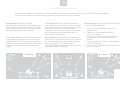
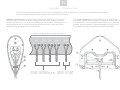
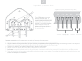
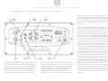
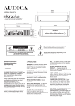
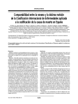
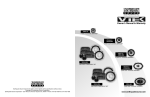
User Manual and
technical specifications
CX-SERIES
GB
3
GB
Welcome
Thank you for choosing AUDICA loudspeakers.
The CX-Series of AV products has been designed and engineered to the highest
standards, combining style with functionality and ergonomics. To extract the best
from your system please refer closely to this manual. It may also be necessary for
you to refer to your other components' user guides to prevent any damage or loss in
performance which may occur from incorrect installation.
Contents
Read this before you begin
-
-
-
-
-
4
System placement
-
-
-
-
-
5
Speaker connection
-
-
-
-
-
6
Subwoofer connection/setup -
-
-
-
-
8
Assembly
-
-
-
-
-
9
Specifications
-
-
-
-
-
42
4
Read These Notes Before Installation
1. GENERAL INFORMATION
4. PRECAUTIONS
The AUDICA CX-Series of loudspeakers consists of
three systems; CX-System 1, CX-System 2 and CXSystem 3. If you are not sure which is your system
then refer to page 42. All systems are passive and
require the use of a 5.1 AV amplifier or 5.1
DVD/Amplifier combination. For specific information on
your amplifier or DVD player refer to your
manufacturer's manual. Please read these instructions
carefully before installing your system and pay
attention to any cautions or recommendations outlined
in this document.
WARNING - To reduce the risk of electric shock do not
remove any panels or covers. There are no user
serviceable parts in this product.
2. UNPACKING YOUR SYSTEM
Care must be taken whilst unpacking your system that
no part is damaged or lost. For an inventory of what
should be supplied with your specific system please
refer to system specifications on page 42. Retain
packaging materials so the system can be re-packed
and shipped if necessary.
3. SERVICING
Do not attempt to service this product yourself as
opening covers or panels may expose you to
dangerous voltages or other hazards. Refer all
servicing to qualified personnel.
Where replacement parts are required be sure the
service technician has used replacements supplied by
the manufacturer or have the same characteristics as
the original part. Use of unsuitable parts could cause
fire, electric shock or other hazards and may void any
warranty or guarantee.
The technician must perform any safety checks to test
the performance of the product upon completion of any
repairs.
WARNING - To reduce the risk of fire or electrical
shock, do not expose this product to rain or moisture.
The product must not be exposed to dripping and
splashing and no object filled with liquids such as a
vase of flowers should be placed on the product.
No naked flame sources such as candles should be
placed on the product.
READ ALL INSTRUCTIONS before attempting to
install or use the product.
RETAIN INSTRUCTIONS for future reference.
HEAT - The product should be kept away from any
heat sources such as radiators, stoves or fires.
ACCESSORIES - Several accessories are provided or
are available specifically for Audica CX-Series
products. Audica cannot hold any responsibility for the
product being damaged whilst being used with third
party accessories such as speaker stands, equipment
racks or wall brackets. Contact your dealer to find out
more about Audica's range of dedicated CX-Series
accessories.
MOVING/TRANSPORTING THE PRODUCT - It is
recommended that the Subwoofer should be moved by
two people due to its weight and size. All product
should be packed in its original packaging for moving
from location to location, for example moving house.
POWER SOURCE - This product should only be
operated using the voltages marked on the Subwoofer
rear panel. If you are not sure of the details of your
home power supply then contact your dealer or local
power company.
Warning: The mains power switch for the subwoofer is
the device used to disconnect the unit from the mains
supply. This switch is located on the rear panel. To
permit free access to this switch, the apparatus must
be located in an open area without any obstructions,
and the switch must be freely operable
OVERLOADING - Never overload mains outlets,
extension cables or multi-way plug extensions as this
may cause fire or electric shock.
POWER CORD PROTECTION - Power supply cords
must be routed away from areas where they are likely
to be walked on or squashed by furniture. Also pay
attention to the placement of extension leads or multiway extension leads.
LIGHTNING - For added protection of the product
during lightning storms or extended periods of non use,
unplug your whole system from the mains outlet and
disconnect your antenna. This will protect your system
from damage due to lightning strikes and power
surges.
5. POWER SUPPLY NOTE
The Subwoofer is supplied with a power cable
terminated with a mains plug. Only replace the fuse
with one of the same specification.
6. GUARANTEE
Audica offer a two year parts and labour warranty.
If you need to return goods for exchange or repair then
it should be returned to your dealer in its original
packaging otherwise your warranty will not be valid.
5
GB
System Placement
It is important to place your speakers in the right position in relation to where you sit in the room. Follow the diagrams below
as closely as possible to maximise the surround sound performance of your speakers.
Front Speakers should be placed
symmetrically in relation to your display. Angle
them towards the point from which you listen.
For the best performance the speakers should
be placed close to the rearward wall.
Your Subwoofer can be placed anywhere in
your room as sub woofers are omni-directional.
We recommend that it is placed within the same
area as your speakers to ensure proper
integration. You must listen to your sub though
as some positions could drastically alter its
performance (see page 8).
The Centre Speaker should be placed ideally
underneath your display. If you have no room
underneath then it could be placed on top but
should be secured with sticky tack. The centre
should be facing outwards in line with your
display.
Rear Speakers can be difficult to place as you
often have no room behind where you choose to
sit. You can experiment with different positions
but, as a guideline, try to place them at
symmetric distances from your listening position
and slightly behind if possible.
General setup can be improved by following a
couple of simple guidelines;
1. Place your front speakers near to the
rearward wall.
2. Place your centre speaker centrally
under your display.
3. Try not to have any obstructions between
the speakers and your ideal listening
position.
4. Set the speakers to 'Small' in your amplifier
or DVD setup menu.
5. Use your own judgement and tastes to fine
tune the system.
6
Speaker GB
Connection
Follow the steps below to setup and connect your speakers to your AV equipment. If you are in doubt about any aspect of
your other equipment then please refer to that manufacturers manual.
Satellites and Towers should be wired up as shown (below left). To prevent
speakers being wired out of phase, always use the printed strand (3) for the
positive red terminal (1) on both the speaker and the amplifier. If the satellite is
wall mounted or sat on a flat surface then thread the wires to the rear of the
speaker using the metal clip pin provided (2)
The Centre Speaker should be wired up as shown (below).
To prevent speakers being wired out of phase, always use the
printed strand (3) for the positive red terminal (1) on both the
speaker and the amplifier. Dress the cables out of the rear of
the speaker through the aperture in the terminal panel.
Amplifier rear panel (actual panel may differ)
CEN
+
TO SPEAKERS
TO SPEAKERS
RR
+
TO SPEAKERS
RL
+
1
1
+
2
CX-C
FREQUENCY
FRÉQUENCE
70Hz-35KHz
TO SPEAKERS
MADE
IN P.R.C
MADE IN P.R.C
Fabriqué en R.P.C.
3
3
TO SOURCE
POWER HANDLING
PUISSANCE ADMISSIBLE
60W-120W
CX-System 1 - CX-LCR (FL,FR)
CX-System 2 - CX-S (FL,FR) CX-S (RL,RR)
CX-System 3 - CX-T (FL,FR) CX-S (FL,FR)
CX-System 1 - CX-LCR (CEN)
CX-System 2 - CX-C (CEN)
CX-System 3 - CX-C (CEN)
TO SPEAKERS
DESIGNED
IN THE EU
TO SPEAKERS
MODEL No. CX-S1
POWER HANDLING
60W-100W
FREQUENCY
80Hz-23KHz
IMPEDANCE
4 Ohms
FR
+
TO SPEAKERS
FL
+
7
GB
Speaker Connection
Amplifier rear panel (actual panel may differ)
1
IMPEDANCE
8 Ohms
CEN
TO SPEAKERS
TO SPEAKERS
+
TO SPEAKERS
TO SPEAKERS
TO SPEAKERS
TO SPEAKERS
FREQUENCY POWER HANDLING
80Hz-23KHz
60W-100W
RR
+
TO SPEAKERS
DESIGNED
IN THE EU
MADE IN P.R.C
MODEL No
CX-C1
RL
+
TO SPEAKERS
+ RH
+ CEN
TO SPEAKERS
+ LH
The LCR Speaker should be
wired up as shown (left). To
prevent speakers being wired out
of phase, always use the printed
strand (3) for the positive red
terminal (1) on both the speaker
and the amplifier. Dress the
cables out of the rear of the
speaker through the aperture in
the terminal panel.
FR
+
TO SPEAKERS
FL
+
CX-System 1- CX-LCR (FL, FR)
CX-S (RL, RR)
CX-System 1 - CX-LCR (CEN)
TO SOURCE
3
Speaker connection can be made easier and safer by following a few easy steps.
TO SOURCE
1. Always have your equipment turned off at the mains before connecting or disconnecting speakers.
2. Lay your cables out to the points where you plan to place your speakers before cutting them to length remembering to allow for the height of
stands or wall mounting. For best results, make sure the left and right cables are the same length.
3. Connect your cables to the speakers before fixing to stands or wall brackets.
4. Always connect the printed side of the cable to the positive or red terminal.
5. Only insert the exposed stripped metal into the terminal post. Inserting the cable too far may result in the plastic sleeve avoiding a proper
connection.
6. Check all connections at the speaker and amplifier end before turning on your system. Connecting the cables incorrectly could short out your
system and damage your equipment.
8
Subwoofer Connection and Setup
The diagram below explains the most effective way to connect your subwoofer.
200
250
X-OVER
(Hz)
7
3
5
100
60
LINE LEVEL
INPUT
AV
R
POWER
MODE
HIGH LEVEL INPUT
R
WARNING: TO REDUCE RISK OF FIRE OR ELECTRIC SHOCK,
DO NOT EXPOSE THIS PRODUCT TO RAIN OR MOISTURE.
WHEN SERVICING, USE ONLY IDENTICAL PARTS
AVERTISSEMENT: POUR DIMINUER LE RISQUE D’INCENDIE OU DE CHOC
ÉLECTRIQUE, NE PAS EXPOSER CE PRODUIT À LA PLUIE OU À L’HUMIDITÉ.
EN CAS DE RÉPARATION, N’UTILISEZ QUE DES PIÉCES IDENTIQUES.
AUTO
10
5
0
6
180°
0°
PHASE
L/LFE
L
AUDICA Ltd, England. Designed and engineered in the EU. Made in the P.R.C.
AUDICA Ltd, Angleterre. Conçu dans I’UE. Fabriqué en P.R.C.
1
The Phase Switch (1) changes the phase of
the sub woofer so that it works in phase with
the rest of the speakers in the system. Place
the subwoofer more than 1 metre away from
the front speakers and switch the phase
between 0° and 180°. When the subwoofer
sounds louder and fuller then it is in phase.
OFF
CX-SUB POWERED
SUBWOOFER
120V
50Hz
CAUTION
RISK OF ELECTRIC SHOCK
DO NOT OPEN
RISQUE DE CHOC ELECTRIQUE
NE PAS OUVRIR
ON
VOLUME
signal from your amplifier it will change to green.
After a period of no signal from your amplifier the
light switches back to red until a further signal is
received. This feature can be overridden by
placing the Power Mode switch (3) in the ON
position.
240V
60Hz
150 Watts
ON
POWER
FUSE TYPE
T 2.5A L/250V
DOUBLE INSULATION
4
2
If there is no difference in sound between the
two switch positions then the sub is placed in a
flat spot. If this is the case then move the sub
woofer to change the distance between it and
the front speakers. The Power Indicator
LED(2) will shine red when the power is
switched on. When the subwoofer receives a
The Line Level Input-LFE (4) is AUDICA's
preferred AV connection to the amplifier. Using
the cable provided, connect this to the Sub
woofer output on your AV amplifier or DVD
player. Use R and L if your amplifier output is
split left and right. . The Crossover control (5)
changes the pitch at which the subwoofer starts
to work. It is recommended that the crossover
point is set to the 'AV' setting on the dial when
used with the CX System. If you are using the
subwoofer with a non-Audica system then you
can change the crossover point to suit your
system. The Volume Control (6) Increases or
decreases the volume of your subwoofer in
relation to the other speakers in the system.
Start with the volume on 0 on the dial then turn it
up slowly until you can hear it. The subwoofer
should be able to be heard as part of the overall
sound and not overpower the rest of the system.
There is no rule for setting the volume on your
subwoofer so experiment with different music
and films to set it to your tastes. High Level
Inputs (7) can be used as the main input for a
subwoofer when used as part of a stereo setup
or if your amplifier does not have a dedicated
subwoofer output. You can connect it by taking a
signal from one of the front speakers by doubling
up the cables from the output terminal on the
amplifier.
9
Assembly of Speakers and Accessories
To attach the base to the CX-T floor
standing speaker (CX-System 3 only)
follow the diagram (right).
1.
Lay the speaker down on a soft
surface and offer the base plate up
to the bottom of the speaker.
2.
Make sure the threaded studs on the
speaker protrude through the
corresponding holes in the plate.
3.
Screw on the nuts and gently
tighten using the spanner provided.
DO NOT OVERTIGHTEN.
4.
For soft floor coverings we
recommend using the spikes. These
are fitted into threaded holes in the
base feet. The height of the spikes
can be adjusted from above using
the allen key provided. Alternatively,
for hard floor coverings you can use
the rubber feet in place of the
spikes.
5.
Finish by fitting the Spike Caps into
the holes on the top of the glass
base.
1,2
3,4
GB