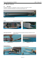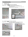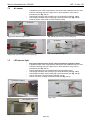
1
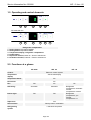
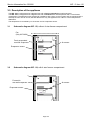
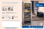
ATAG
KD8088AD
KD8102AD
KD8102BD
KD8140BD
Service Information No. 05/2006
IKP ..5. from -20
Contents
1.0
2.0
3.0
3.1
3.2
4.0
4.1
4.2
5.0
6.0
6.1
7.0
7.1
Operating and control elements
Functions at a glance
Description of the appliance
Schematic diagram IKP ..50, without 4-star freezer compartment
Schematic diagram IKP ..54, with 4-star freezer compartment
Control and functional components
Refrigerator compartment
Freezer compartment
Refrigeration circuit
Special features
Soft stop
Assembly instructions
Evaporator sensor
7.1.1 Appliances without 4-star freezer compartment
7.1.2 Appliances with 4-star freezer compartment
7.2
7.3
7.4
7.5
7.6
7.7
8.0
9.0
9.1
9.2
9.3
10.0
Air sensor
LED interior light
-Only IKP 2850- fan
Integral PCB
Door magnet
Support rails for sectioned glass shelves
Technical data
Service menu
Demo mode "d0"
Service mode "L"
Sensor test (temperature display) and door contact test "E"
Table of error codes
Page 2/16
3
3
4
4
4
5
5
6
6
7
7
8
8
8
8
9
9
10
11
13
13
14
15
15
15
16
16
Service Information No. 05/2006
IKP ..5. from -20
1.0 Operating and control elements
1
2
3
4
5
2
3
4
5
IKP 2850 with fan
1
6
Refrigerator compartment
1 : Setting button temperature higher
2 : Setting button temperature lower
3 : Temperature display, refrigerator compartment
4 : On/Off button
5 : SuperCool function, button lit = function switched on.
6 : Ventilation function, button lit = function switched on.
2.0 Functions at a glance
IKP 2850
IKP ..50
Electronic control system
Control:
Actual value display
Temperature
display:
Temperature alarm:
No
Door alarm:
No
Fan:
Defrosting:
Interior light:
IKP ..54
Yes
No
No
Automatic
Automatic
Refrigerator
compartment: automatic
Freezer
compartment: manual
Yes
Yes
Yes
SuperCool:
Service menu:
Start by button combination
Refrigerating
system:
1 standard compressor
Page 3/16
Refrigerator
compartment: yes
Freezer
compartment: no
Service Information No. 05/2006
IKP ..5. from -20
3.0 Description of the appliance
The IKP ..50 are refrigerators for integrated use with a freely suspended rear wall evaporator.
The IKP ..54 are refrigerators for integrated use with a foamed-in rear wall evaporator and a 4-star freezer
compartment. The appliances are prepared for installation with a door-on-door system and are equipped with a
soft stop function. Due to its size, the IKP 2850 as the only IKP appliance has a fan for uniform temperature
distribution.
The temperature is controlled by an air sensor and an evaporator sensor.
3.1
Schematic diagram IKP ..50, without 4-star freezer compartment
Fan
(Only IKP 2850)
Freely suspended
rear wall evaporator
Air sensor
Evaporator sensor
Fig. 3.1
3.2
Schematic diagram IKP ..54, with 4-star freezer compartment
Foamed-in
rear wall evaporator
Air sensor
Evaporator sensor
Fig. 3.2
Page 4/16
Service Information No. 05/2006
IKP ..5. from -20
4.0 Control and functional components
4.1
Refrigerator compartment
Electr. control system:
Series 6 electronic control system: integral PCB.
Setting range:
+2°C to +9°C
Display range:
2°C to 50°C
Door alarm:
No
Interior light:
Position:
Inside right.
Function:
- Is switched on as soon as refrigerator compartment door is
opened.
- Is switched off after door has been open for 15 minutes.
Attention:
230V applied to the LEDs.
Position:
In front panel.
Function:
Switches the interior light on when the door is opened.
Only IKP 2850:
Turns off the fan (if activated) when the door is opened.
Position:
In light housing.
Function:
- Switches the compressor off.
Position:
In IKP ..50: In the sensor pocket on the rear of the evaporator.
In IKP ..54: In sensor holder on compartment liner rear wall.
Function:
Switches compressor on.
Reed PCB:
Air sensor:
Evaporator sensor:
SuperCool:
With SuperCool the appliance switches to the coldest control setting for 6 hours.
In IKP ..54: The freezer compartment becomes correspondingly colder.
Defrosting:
Automatic during standstill phase of the compressor.
Fan:
(Only IKP 2850)
Position:
At the centre back of the ceiling of the compartment liner.
Function:
ON:
- Fan switch ON
and
- Compressor ON
and
- Refrigerator compartment door closed
OFF:
- Fan switch OFF
or
- Compressor OFF
or
- Refrigerator compartment door open
During start-up the fan is activated only from an evaporator sensor
temperature of +8°C and colder.
Compressor:
Function:
ON:
- Refrigerator compartment evaporator sensor switch-on
value
Note: On-delay time (8 mins.) must have elapsed.
OFF:
- Refrigerator compartment air sensor switch-off value
Page 5/16
Service Information No. 05/2006
4.2
IKP ..5. from -20
Freezer compartment
Electronic control
system:
See 4.1 Refrigerator compartment.
Setting range:
Dependent on refrigerator compartment setting
Display range:
No display
Compressor:
See 4.1 Refrigerator compartment -compressor-
5.0 Refrigeration circuit
Evaporator:
Injection point/
flow sequence:
Compressor:
IKP ..50:
Freely suspended evaporator.
IKP ..54:
Foamed-in rear wall evaporator + foamed-in
wound around freezer compartment evaporator.
IKP ..50:
Introduction of refrigerant in refrigerator compartment evaporator
top left.
IKP ..54:
Introduction of refrigerant in freezer compartment evaporator 1st
winding at the front, then transition to the refrigerator compartment
evaporator.
Entry into refrigerator compartment evaporator: top right.
Exit from refrigerator compartment evaporator into the suction line:
top left.
1 standard compressor.
On-delay time of 8 mins.
Page 6/16
Service Information No. 05/2006
IKP ..5. from -20
6.0 Special features
6.1
Soft stop
Integrated on the door, the SoftSystem cushions movement when the door is closed.
The door is closed automatically from an opening angle of approx. 30°.
Fig. 6.1/ 1 Soft stop mechanism
Cover:
Disengage and detach cover.
Fig. 6.1/ 3 Cover, front
Fig. 6.1/ 2 Cover, rear
Soft stop mechanism:
Unlock retaining spring and detach soft stop mechanism from the
spherical head.
Fig. 6.1/ 4 Detaching soft stop mechanism from
spherical head
Fixing bracket of
soft stop mechanism:
Fig. 6.1/ 5 Soft stop mechanism
detached
Undo screw and detach soft stop mechanism.
Fig. 6.1/ 6 Screw of hinge fixture
Fig. 6.1/ 7 Fixing bracket
Page 7/16
Service Information No. 05/2006
IKP ..5. from -20
7.0 Assembly instructions
7.1
Evaporator sensor
7.1.1
Appliances without 4-star freezer compartment
Evaporator sensor:
-
Remove glass shelves and glass shelf supports.
Undo screws of the evaporator suspension (see Fig.7.1.1/ 1)
Swing evaporator to the left.
Pull off the strip about 20 cm, starting from the bottom (see Fig. 7.1.1/ 2).
Pull evaporator sensor out of sensor pocket.
Evaporator sensor
Evaporator sensor position
Fig. 7.1.1/ 1
7.1.2
Fig. 7.1.1/ 2 Evaporator sensor
Appliances with 4-star freezer compartment
Evaporator sensor:
-
Unclip evaporator sensor cover at the marked point and remove it.
Undo screw of the evaporator sensor fastening (see Fig. 7.1.2/ 2)
Unclip evaporator sensor from the fastening plate.
Evaporator sensor position
Evaporator sensor cover
Fig. 7.1.2/ 1 Cover
Fig. 7.1.2/ 2 Position
Evaporator sensor
Fig. 7.1.2/ 3 Evaporator sensor
Page 8/16
Service Information No. 05/2006
7.2
IKP ..5. from -20
Air sensor
-
In appliances with 4-star compartment, first remove the evaporator sensor cover.
Unlock the locating lugs of the light cover in arrow direction, using a short
screwdriver (see Fig. 7.2/ 1).
Unlock light housing at rear locating lug in arrow direction (see Fig. 7.2/ 2)
Unlock light housing at front locating lug in arrow direction (see Fig. 7.2/ 3)
Unclip air sensor from holder on back of light housing.
Air sensor
Light cover
Fig. 7.2/ 1 Detaching light cover
Fig. 7.2/ 2 Light housing, rear locating lug
Air sensor
Fig. 7.2/ 3 Light housing, front locating lug
7.3
Fig. 7.2/ 4 Light housing back
LED interior light
-
Disconnect appliance from mains supply as 230V are applied to LEDs!
In appliances with 4-star compartment, first remove the evaporator sensor cover.
Unlock the locating lugs of the light cover in arrow direction, using a short
screwdriver (see Fig. 7.2/ 1).
Unlock LED lighting unit at marked locating lugs (see Fig. 7.3/ 1).
Unlock light housing at rear locating lug in arrow direction (see Fig. 7.2/ 2)
Unlock light housing at front locating lug in arrow direction (see Fig. 7.2/ 3)
Unlock connector in arrow direction (see Fig. 7.3/ 2)
Unlock connector coupling in arrow direction (see Fig. 7.3/ 1).
Connector coupling
Fig. 7.3/ 1
Fig. 7.3/ 2
LED lighting unit
Fig. 7.3/ 3 LED lighting unit
Page 9/16
Service Information No. 05/2006
7.4
IKP ..5. from -20
-Only IKP 2850- fan
-
Undo fastening screws of the fan (see Fig. 7.4/ 2).
Pull off connecting cable (see Fig. 7.4/ 3).
Unlock locating lugs of the fan cover (see Fig. 7.4/ 4) and remove fan cover in a
forward direction.
Lift fan motor out of the fan housing.
Fig. 7.4 / 1 Fan
Fig. 7.4/ 2 Fastening screws
Locating lugs
Fig. 7.4/ 3 Cable routing
Fig. 7.4/ 4 Fan cover
Fan casing
Fan motor
Fan cover
Fig. 7.4/ 5 Fan components
Page 10/16
Service Information No. 05/2006
7.5
IKP ..5. from -20
Integral PCB
Covers:
Disengage covers at the marked points.
Fig. 7.5/ 1
Front panel:
Unlock locating lugs at the left and right of the front casing.
Fig. 7.5/ 2
PCB carrier:
Draw out front casing in a forward direction and uncover the cables.
Fig. 7.5/ 3
Group connector:
Press down lock and pull off group connector.
Fig. 7.5/ 4
Page 11/16
Service Information No. 05/2006
Front panel:
IKP ..5. from -20
Release marked locks and remove front panel.
Fig. 7.5/ 5
PCB:
Release reed PCB and marked locks using a screwdriver and pull PCB
sideways out of the PCB carrier.
Fig. 7.5/ 6
Fig. 7.5/ 7
Page 12/16
Service Information No. 05/2006
7.6
IKP ..5. from -20
Door magnet
Magnet holder:
Press marked locating lugs together and detach magnet holder upwardly.
Magnet
Fig. 7.6/ 2
Fig. 7.6/ 1
7.7
Support rails for sectioned glass shelves
Rails:
These plastic rails support the sectioned glass shelves. The marking R for right and
L for left is impressed inside. The toothed profile has to rest against the underside
of the supporting ribs of the compartment liner.
Support rail
Toothed profile for
better fixation
Fig. 7.7/ 1
Fig. 7.7/ 2
Page 13/16
Service Information No. 05/2006
IKP ..5. from -20
8.0 Technical data
Interior light:
Wattage:
Voltage:
3 watts
230 volts
Fan:
(Only IKP 2850)
Wattage:
Voltage:
Speed:
8.5 watts
230 volts
1700 rpm.
Sensor values:
Air and evaporator sensor
Temperature °C
Resistance value kOhm
+35
+30
+25
+20
+15
+10
+5
0
-5
-10
-15
-20
-25
-30
-35
3.1
3.8
4.7
5.9
7.3
9.3
11.9
15.3
19.8
25.9
34.1
45.3
60.8
82.3
112.8
Page 14/16
Service Information No. 05/2006
IKP ..5. from -20
9.0 Service menu
The service menu may be used only by customer service technicians.
IKP 2850 with fan
9.1
Demo mode "d0"
•
Press SuperCool and On/Off simultaneously for 3 seconds.
•
"d1" or "d0", the SuperCool LED flash.
•
d1 = demo mode is deactivated. To activate the demo mode, press SuperCool.
•
d0 = demo mode is activated. To deactivate the demo mode, press SuperCool.
•
If no change is required, SuperCool must not be pressed, but On/Off.
• When the demo mode is active, compressor and fans are not activated.
Attention: The demo mode cannot be deactivated by power OFF/ON.
This is possible only via the service menu.
9.2
Service mode "L"
•
Press SuperCool and On/Off simultaneously for 3 seconds.
•
"d1" or "d0", the SuperCool LED flash.
•
Press "Up" once.
•
Press SuperCool, you are now in the service mode.
•
"rd" flashes.
•
Open and close door.
•
All segments and LEDs are lit.
•
Press all the buttons. Every press of a button is confirmed by a signal tone.
•
2 seconds signal tone. Control panel test concluded - load test active.
•
Display "L0".
•
All the loads can be individually addressed using "Up" or "Down".
- L0: No load addressed
- L2: Compressor
- L5: LED interior light
- L7: Fan (Only IKP 2850)
• End with On/Off.
Page 15/16
Service Information No. 05/2006
9.3
IKP ..5. from -20
Sensor test (temperature display) and door contact test "E"
• Press SuperCool and On/Off simultaneously for 3 seconds.
• "d1" or "d0", the SuperCool LED flash.
• Press "Up" twice. "E" flashes.
• Press SuperCool.
• The appliance is in sensor test mode and operates in the service mode.
All the sensors and their current temperature values can be displayed with "Up" and "Down".
- E1: Refrigerator compartment air sensor
- E2: Evaporator sensor for refrigerator compartment
- E9: Door contact (0= door closed, 1 = door open)
• End by pressing On/Off twice.
10.0 Table of error codes
Error code
Defective component
F1
Air sensor
F2
Evaporator sensor
FA, FC, Fd,
FP
F6, F7, F8,
F9, SE
Emergency operation
Without 4-star freezer compartment
10 min. ON, 40 min. OFF
With 4-star freezer compartment
20 min. ON, 40 min. OFF
Without 4-star freezer compartment
10 min. ON, 40 min. OFF
With 4-star freezer compartment
20 min. ON, 40 min. OFF
Only for factory testing.
Only for factory testing.
-
Page 16/16
AEP Home Products
Impact 54 – 6921 RZ
Postbus 249 – 6920 AE Duiven – Nederland