1
ATARI
400/800
Service Manual
CHAPTER
1 - GENERAL INFORMATION
1.1 Introduction
1.2 ATARI 400/800 Computer Console Description
1.3 How to use this Manual
1.3.1 General Information
1.3.2 Installation
1.3.3 System Operation
1.3.4 Functional Description
1.3.5 Maintenance
1.3.6 Spare Parts List and
Ordering/Reporting information
1.4 Changes to this Manual
1.4.1 Notice of Changes Page
1.4.2 List of Effective Pages
1.4.3 Reader Comment Form
1.5 Safety
1.6 Related documentation
1.7 ATARI 400/800 Computer Consoles
Physical Description
1.8 Optional Equipment
1.9 Specifications
CHAPTER
2 - ATARI 400/800 COMPUTER INSTALLATION
2.1 Introduction
2.2 Unpacking
2.3 Connecting the TV Switch Box
2.4 Connecting the Program Cassette Recorder
2.5 Connecting the AC Power Adapter
2.6 Inserting Program Cartridge
2.7 Connecting Television Monitor
2.8 Connecting the ATARI 810 and 815 Disk Drive
2.9 Connecting the ATARI 820 and 822 Printer
2.10 Using the ATARI 850 Interface Module
2.10.1 Connecting the ATARI 850 Interface Module
2.10.2 Connecting the ATARI 825 Printer
2.10.3 Connecting the ATARI 830 Acoustic Modem
CHAPTER 3 - SYSTEM OPERATION
3.1 Introduction
3.2 System Power-Up
3.2.1 System Power-Up without Disk Drive
3.2.2 System Power-Up with Disk Drive
3.3 Keyboard and Screen Editor Functions
3.4 Program Cartridge System Keys
3.5 Operation of Hand Controllers
3.6 ATARI 410 Program Cassette Recorder
3.6.1 Operation of the Program Recorder
3.6.2 Transfer a Program to Cassette Tape
3.6.3 Transfer a Program from Tape to Computer
CHAPTER 4 - FUNCTIONAL DESCRIPTION
4.1 Introduction
1-1
1-1
1-1
1-2
1-3
1-3
1-3
1-3
1-3
1-4
1-4
1-4
1-4
1-4
1-5
1-6
1-7
1-10
1-11
2-1
2-1
2-1
2-2
2-3
2-4
2-4
2-4
2-7
2-7
2-8
2-8
2-9
2-10
3-1
3-1
3-1
3-1
3-2
3-2
3-7
3-7
3-7
3-7
3-8
3-9
4-1
4-1
4.2 The ATARI 400 and 800 Computer Console Systems
4.2.1 Motherboard
4.2.2 Central Processing Unit
4.2.3 ROM Personality Board
4.2.4 RAM Memory pcb
4.2.5 Keyboard
4.2.6 Power Supply
4.2.7 Program Cartridge
4.3 Functional Block Diagram Discussion
4.3.1 Central Processing Unit
4.3.2 Motherboard Console System {400)
4.3.2.1 POKEY Integrated Circuit
4.3.2.2 Peripheral Interface Adapter (PIA)
4.3.2.3 KeyIn/KeyOut Integrated Circuits
4.3.2.4 Memory Map Decoder
4.3.2.5 I/O Decoder
4.3.3 Motherboard Console System (800)
4.3.3.1 Bidirectional Data Buffer
4.3.3.2 I/O Decoder
4.3.3.3 Composite Video
4.3.4 ROM Personality Board
4.3.5 RAM Memory Boards
4.3.6 Power Supply
4.3.7 Program Cartridge
CHAPTER 5 - MAINTENANCE
5.1 Introduction
5.2 Preventive Maintenance
5.2.1 PCB Contact Cleaning and Lubrication
5.2.2 Visually Inspecting the Computer Consoles
5.3 System Check-Out
5.3.1 Memo Pad Test
5.3.2 Shock Test
5.3.3 Picture Quality Test
5.3.4 Keyboard Test
5.3.5 Stand Alone Test (Diagnostic)
5.4 Troubleshooting Guide
5.4.1 Troubleshooting -- Procedure Number One
5.4.2 Troubleshooting -- Procedure Number Two
5.4.3 Troubleshooting -- Procedure Number Three
5.4.4 Integrated Circuit Replacement Procedures
5.4.5 Motherboard
5.5 Dissassembly, 400Computer Console
5.6 Disassembly, 800 Computer Console
5.7 Assembly, 400 Computer Console
5.8 Assembly, 800 Computer Console
CHAPTER 6 - SPARE PARTS LIST AND ORDERING/REPORTING INFORMATION
6.1 Introduction
6.2 Spare Parts List
4-1
4-1
4-2
4-3
4-3
4-4
4-4
4-4
4-4
4-5
4-7
4-8
4-9
4-12
4-12
4-13
4-14
4-14
4-14
4-14
4-14
4-16
4-16
4-17
5-1
5-1
5-1
5-2
5-3
5-3
5-3
5-5
5-5
5-6
5-7
5-18
5-19
5-21
5-23
5-23
5-27
5-30
5-33
5-40
5-43
6-1
6-1
6-1
FIGURES
Figure
Figure
Figure
Figure
Figure
Figure
Figure
Figure
Figure
Figure
Figure
Figure
Figure
Figure
Figure
Figure
Figure
Figure
Figure
Figure
Figure
Figure
Figure
Figure
Figure
Figure
Figure
Figure
Figure
Figure
Figure
Figure
Figure
Figure
Figure
Figure
Figure
Figure
Figure
Figure
Figure
Figure
Figure
Figure
Figure
Figure
Figure
Figure
Figure
Figure
Figure
Figure
Figure
1-1. The ATARI 400/800 Computer Consoles
1-2
1-2. Sample Notice of Changes Page
1-5
1-3. ATARI 400/800 Computer Console Systems
1-8
1-4. ATARI 400 Computer Console, Side View
1-9
1-5. ATARI 800 Computer Console, Side View
1-10
2-1. Conversion to 300 Ohm Antenna Input Impedance
2-3
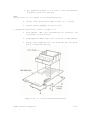
2-2. ATARI 400/800 Computer Consoles, Side View
2-5
2-3. 400/800 Consoles, Cartridge Door Open
2-6
2-4. ATARI Disk Drive Cable Connections
2-8
2-5. ATARI 40 Column Printer Cable Connections
2-9
2-6. ATARI 850 Interface Module Cable Diagram
2-10
3-1. The ATARI Keyboard
3-3
3-2. Special Graphics Using the CTRL Key
3-4
3-3. Special Graphics Using the ESC Key
3-5
3-4. SHIFT Keyboard and Key Combination
3-6
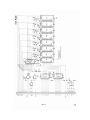
4-1. Major Functional Modules of the ATARI 400/800
4-18
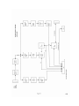
4-2. Block Diagram of the CPU Board
4-19
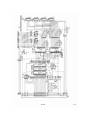
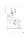
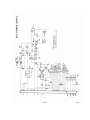
4-3. Schematic Diagram of the CPU Board
4-20
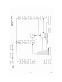
4-4. Atari 400 motherboard Block Diagram
4-21
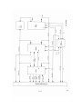
4-5a. Atari 400 motherboard schematic part 1
4-22
4-5b. Atari 400 motherboard schematic part 2
4-23
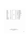
4-6. Pin Assignments of ATARI Custom Chips POKEY,
ANTIC and CTIA
4-24
4-7. Block Diagram of the Motherboard Console System (800) 4-27
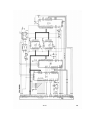
4-8a. Schematic Diagram of Motherboard Console System(800) 4-28
4-8b. Schematic Diagram of Motherboard Console System(800) 4-29
4-9. Block Diagram of the ROM Personality Board
4-30
4-10. Schematic Diagram of the ROM Personality Board
4-31
4-11. Block Diagram of the RAM Board (8K)
4-32
4-12. Schematic Diagram of the RAM Board (8K)
4-33
4-13. Block Diagram of the RAM Board (16K)
4-34
4-14. Schematic Diagram of the RAM Board (16K)
4-35
4-15. Block Diagram of the Power Supply (400)
4-36
4-16. Schematic Diagram of the Power Supply (400)
4-37
4-17. Block Diagram of the Power Supply (800)
4-38
4-18. Schematic Diagram of the Power Supply (800)
4-39
4-19. Block Diagram of a Program Cartridge
4-40
4-20. Schematic Diagram of a Program Cartridge
4-41
5-1. System Check-Out Flowchart
5-4
5-2. Stand Alone Test Special Tools
5-8
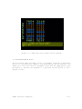
5-3. Any Video Test Screen Display
5-10
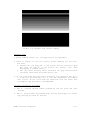
5-4. Graybar Test Screen Display
5-11
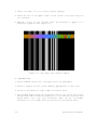
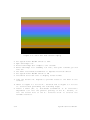
5-5. Color Bar Test Screen Display
5-12
5-6.400 Console Color Adjustment
5-13
5-7. 800 Console Color Adjustment
5-14
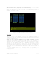
5-8. RAM Test Matrix Screen Display
5-15
5-9. PORT Test Error Table Screen Display
5-17
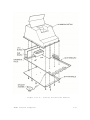
5-10. 400 Console, Assembled Without Casting
5-20
5-11. 800 Console, Assembled Without Casting
5-21
5-12. RAM Memory Board Locations, 8K
5-24
5-13. RAM Memory Board Locations, 16K
5-25
5-14. CPU Printed Circuit Board, Locations
5-26
5-15. 400 Console Motherboard, Locations
5-28
5-16. 800 Console Motherboard, Locations
5-29
Figure
Figure
Figure
Figure
Figure
Figure
Figure
Figure
Figure
Figure
Figure
Figure
5-17.
5-18.
5-19.
5-20.
5-21.
5-22.
5-23.
5-24.
5-25.
5-26.
5-27.
5-28.
400
400
400
400
400
800
800
800
800
800
800
800
Console,
Console,
Console,
Console,
Console,
Console,
Console,
Console,
Console,
Console,
Console,
Console,
Bottom Cover Screw Location
Top Cover Removal
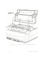
Keyboard Removal
Power Supply Removal
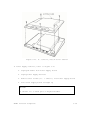
Module Assembly
Cartridge Door Assembly Removal
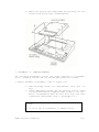
Bottom Cover Removal
Keyboard Removal
Module Assembly Removal
Power Supply Removal
CPU Printed Circuit Board Removal
Motherboard Removal
5-31
5-32
5-32
5-35
5-36
5-37
5-38
5-39
5-40
5-41
5-41
5-42
TABLES
Table 1-1.
Table 1-2.
Table 4-1
Table 4-2
Table 4-3
Table 5-1.
ATARI 400 Computer Console Specifications
ATARI 800 Computer Console Specifications
PIA Register Selection and Function
Memory Map Select Lines
I/O Decoder Select Lines
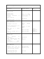
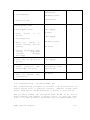
Troubleshooting Guide
1-11
1-12
4-10
4-12
4-13
5-18
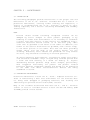
CHAPTER 1 - GENERAL INFORMATION
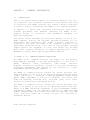
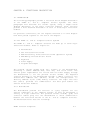
1.1
INTRODUCTION
This 400/800 System Service Manual is a reference guide for the service technician. The information presented in this manual, when used
in conjunction with ATARI training, will enable a service technician
to install, operate, and maintain the ATARI 400/800 Computer Systems.
In addition to basic user operating instructions, this manual
includes procedures that describe operating the ATARI 400/800
Computer Console in conjunction with peripheral equipment for
maintenance purposes.
This manual further describes the functional operation of the 400/800
ATARI Computer Consoles and provides detailed procedures for its
maintenance. This information will enable a service technician to
troubleshoot and repair the ATARI 400/800 Computer Consoles to the
replaceable integrated circuit level. None of the procedures included
require special test equipment or tools. This manual also provides
spare parts ordering information to replace expended units and/or
assemblies, and the fault reporting procedures required.
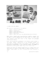
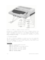
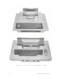
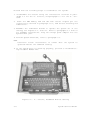
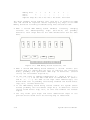
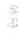
1.2 ATARI 400/800 COMPUTER CONSOLE DESCRIPTION
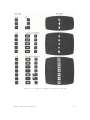
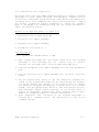
The ATARI 400/800 Computer Consoles, see Figure 1-1, are personal
microcomputers designed to provide entertainment, in the form of
games;
education,
using
interactive,
audio-visual,
education
programs; information, providing a serious tool for home and business
information management; plus perform all the functions of a fully
programmable general purpose computer.
The ATARI 400 Computer Console contains the central processor unit
(CPU) and memory in the form of the Operating System read-only-memory
( ROM ) and 8K (8 x 1 024 bytes) of user programmable random access
memory (RAM), expandable to 16K (16 x 1024 bytes). The Console also
holds the keyboard, cartridge slot, controller jacks, and a serial
I/O port for connecting to peripheral devices.
The ATARI 800 Computer Console contains the central processor unit
(CPU) a nd memory in the form of the Operating System read-onlymemory (10K ROM) and 8K-16K (standard) of user programmable randomaccessmemory (RAM), and two Expansion Sockets for additional RAM
modules (maximun 48K). The Console also holds the keyboard, cartridge
slots, controller jacks and a serial I/O port for connecting to
peripheral devices.
Atari Personal Computers
1-1
Figure 1-1. The ATARI 400/800 Computer Consoles
1.3 HOW TO USE THIS MANUAL
This manual is organized into six chapters:
Chapter
Chapter
Chapter
Chapter
Chapter
Chapter
1
2
3
4
5
6
General Information
Installation
System Operation
Functional Description
Maintenance
Spare Parts List and Ordering/Reporting Information
Each chapter contains only the information
function. If a given subject applies to more
the subject will be discussed in the chapter
other chapters would then refer to the
containing the subject.
needed to fulfill its
than one chapter, then
where it is most used;
chapter and paragraph
First- and second-level paragraphs in the manual contain unique 2and 3-digit numbers, respectively, in the paragraph heading. The
first digit is always the same as the number of the chapter. Thirdand forth-level paragraphs contain lower case letters and numbers in
parentheses, respectively, in the paragraph heading. Paragraghs are
referenced in text by their number (e.g., 5.4.2 a nd 5.4.9c).
Figures and tables are numbered sequentially on a chapter basis. The
first digit of a figure or table number is always the numbe r of the
chapter. Tables appear one time, following their first reference in
text.
1-2
System Service Manual
Figures also appear one time after their first reference in text,
unless repeating the figure is easier than having the reader refer
back.
1.3.1 General Information
This chapter contains a general description of the ATARI 400/800 Computer Consoles, a physical description of the system (dimensions,
weights, and operating specifications), and a summary of the peripheral equipment used with the system. All system operating features
and options are described.
This chapter also contains general information such as the scope of
the manual and how to use the information in it. Also, it provides
safety precautions unique to the ATARI 400/800 Computer Systems and a
listing of related documents.
1.3.2 Installation
Chapter 2 contains detailed procedures for unpacking, system setup
and initialization, checkout and repacking.
1.3.3 System Operation
Chapter 3 contains procedures for system power-up, using the keyboard
and screen editor functions, using program cartridge system keys, and
controllers and operating the program cassette recorder.
1.3.4 Functional Description
Chapter 4 provides a functional description of the ATARI 400/800 Computer Console systems. The functional description will be presented
using a functional block diagram discussion to the integrated circuit
level. This information is presented to familiarize the service technician with the ATARI 400/800 Computer Console as a system, thereby
providing him/her with a basis for troubleshooting system faults.
1.3.5 Maintenance
Chapter 5 presents preventive maintenance, troubleshooting, and
repair instructions. Preventive maintenance includes instructions for
normal cleaning and inspection tasks. The troubleshooting portion of
the chapter presents symptom probable-cause corrective action types
of tables. The repair portion of the chapter provides instructions
for replacing printed circuit assemblies, whole assemblies, and
specific integrated circuits in keeping with the ATARI maintenance
philosophy.
ATARI Personal Computers
1.3.6 Spare Parts List and Ordering/Reporting Information
1-3
Chapter 6 provides ATARI part numbers for the field replaceable units
of the 400/800 Computer Console system. The chapter also provides
information for ordering the parts through the nearest ATARI parts
distribution center. In addition chapter 6 provides information on
how to use the Fault Reporting System.
1.4 CHANGES TO THIS MANUAL
This manual will periodically be updated or changed to keep it
current with changes in the ATARI 400/800 Computer Console systems.
Changes normally start with ATARI Customer Support issuing a "Tech
Tips" that alerts the service technician to such things as changes in
maintenance procedures and critical problem areas. After either a
series of these Tech Tips are issued or one of an extremely critical
nature is issued, service manual change pages are published. These
pages are of the remove-the-old-and-insert-the-new type. A vertical
bar in the margin of the changed page indicates the revised material.
After about 20% of a manuals pages are changed, Customer Support
Publications reissues the entire manual.
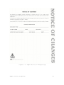
1.4.1 Notice of Changes Page
The Notice of Changes page, see Figure 1-2, contains instructions for
changing this manual. It will come with pages intended to replace
outdated pages in the manual. The Notice contains the affected page
number and the action required to make the changes. After making the
necessary changes, insert the Notice at the end of the manual to keep
a current record of changes.
1.4.2 List of Effective Pages
The List of Effective Pages on the back of this manual's title page
lists all the pages in this book, including the title page, the List
of Effective Pages, deleted pages, added pages, and foldout pages.
1.4.3 Reader Comment Form
ATARI Customer Support Publications Department created the Reader
Comment Form (at the back of this manual) to get feedback from the
service technician about our manuals. If you are in any way
dissatified with this publication, we want to hear from you. Tell us
about technically inaccurate information, gross typographical errors,
or missing information. If you know a way to improve a procedure,
please let us know that, too. When filling out the form, be specific
and give the page number and a line reference with paragraph number,
if possible.
1-4
System Service Manual
Figure 1-2. Sample Notice of Changes Page
ATARI Personal Computers
1-5
1.5 SAFETY
As with any electronic equipment, precautions consistent with all
standard industrial safety practices must be observed while maintaining the ATARI 400/800 Computer Console systems. A current of 10 mA
can put the human heart in fibrillation and a current of only 100 mA
can cause it to stop completely. Since human skin resistance is normally about 300 ohms, any voltage in excess of 30 volts ran be
lethal.
Notices are included throughout this manual to alert you to problem
areas or dangerous situations.
A WARNING statement will precede the text of a procedure that, if not
strictly observed, could result in injury or death of the service
technician.
A CAUTION statement will precede the text of a procedure that, if not
strictly observed, could result in damage to or destruction of equipment hardware or software.
A NOTE statement will highlight an essential operating or maintenance
procedure, condition, or clarifying fact. Notes will also be used to
provide information that, though not necessary, will be helpful to
understanding a concept or completion of a procedure.
1.6 RELATED DOCUMENTATION
This service manual provides only that information necessary for a
service technician to install, operate, and maintain the ATARI
400/800 Computer Console systems.
Other documents published by ATARI, other manufacturers, and publishing houses may be helpful to the service technician. The following
documents apply directly to the ATARI 400/800 Computer Consoles systems:
ATARI
ATARI
ATARI
ATARI
ATARI
ATARI
400 Operator's Manual
800 Operator's Manual
810 Disk Drive Operator's Manual
820 Printer Operator's Manual
400/800 Basic Reference Manual
BASIC
CO14768
CO14769
CO14760
CO14762
CO15307
CO14385
1-6
System Service Manual
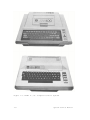
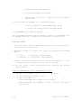
1.7 ATARI 400/800 COMPUTER CONSOLES PHYSICAL DESCRIPTION
The ATARI 400 and 800 Computer Consoles are general purpose microcomputers based upon the 6502 microprocessor. The ATARI 400/800 Consoles, see Figure 1-3, are the central processing units (CPU) for
their respective systems. Each console comes standard with a built in
keyboard. 8K/16K of RAM, ROM operating systems, connector jacks for
adding peripherals and hand controllers, and a 15 foot RF cable for
connection to a user's television set.
The controller jacks on the front of both the 400 and 800 Consoles
accept any of the three types of hand controllers available from
ATARI.
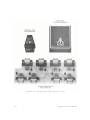
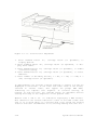
The side panel of the 400 Console, see
eral jack, power ON/OFF switch, and
switch is located on the ba ck of the
to channel 2 o r channel 3 transmission
Figure 1-4, contains a peripha power jack. A channel 2/3
console to switch the console
frequency.
The side panel of the 800 Console, see Figure 1-5, contains a monitor
jack, a peripheral jack, a channel 2/3 switch, a power ON/OFF switch,
and a power jack.
Both the 400 and 800 Console keyboards provide a full alphanumeric
character set, cursor controls, and special purpose keys. The alphabet keys when used in conjunction with the CTRL (Control) key become
special graphic symbols. To the right of the keyboard is the power ON
light and four special control switches. From top to bottom they are:
SYSTEM RESET - Interrupts whatever the computer is doing and restarts
the Operating System or Program Cartridge
OPTION - Interrupt used by the Program Cartridge to choose amoung the
variations within a game or program
SELECT - Interrupt used to select one of several games or
programs in the Program Cartridge
START - Interrupt used to Start the game or program selected from the
Program Cartridge
The AC Power Adapter provides the 9 Vac used by the 400 and 800 Computer Consoles. The AC Power Adapter plugs into a standard wall outlet and converts the 110V ac line voltage to the 9V ac required by
the Consoles. The power cord from the AC Power Adapter plugs into the
power jack on either the 400 or 800 Console.
The TV Switch Box allows the 400/800 Computer Console to be connected
to the normal 300 ohm RF antenna inputs on a typical television set.
The Proqram Cassette Recorder provides 400K bytes of storage (120
ATARI Personal Computers
1-7
Figure 1-3. ATARI 400/800 Computer Console Systems
1-8
System Service Manual
Figure 1-4. ATARI 400 Computer Console, Side View
minute cassette) for the Consoles. The Program Cassette Recorder
plugs into the peripheral serial I/O port. The Program Cassette
Recorder has two channels, a data channel for video display and an
audio channel. Prerecorded tape contains an audio track that allows
narration and music to accompany the tapes using the television
speakers. Programs recorded by the user onto cassette tape can only
record on the data channel. There are six control buttons on the
Program Cassette Recorder, from left to right they are:
1.
2.
3.
4.
5.
6.
7.
Record
Rewind
P1ay
Advance (fast forward)
Stop/Eject
Tape Counter Reset Button
Pause (Available on some models)
The "BASIC" Program Catridge provided as a standard feature with both
the 400 and 800 Computer Consoles contains the ATARI BASIC
Interpreter When plugged into the Console Cartridge Slot (one
cartridge slot in the 400 Console, left cartridge slot in the 800
Console) the user can write programs in 'BASIC' programming lanquage.
Programs written by the user are stored in the Console's RAM memory
and are erased when power is turned off. The BASIC Program Cartridge
is marked 'LEFT CARTRIDGE' indicating insertion in the left cartridge
slot only. An ATARI Educational System Program Cartridge and cassette
tapes are
ATARI Personal Computers
1-9
Figure 1-5. ATARI 800 Computer Console, Side View
provided as a standard feature with the 800 Computer Console. The
Program Cartridge when inserted in the Computer Cartridge slot provides a self-paced learning tool. The Program prompts the student
with instructions when to load additional information from the
Program Cassette Recorder.
1.8 OPTIONAL EQUIPMENT
The list of optional equipment is broken up into two catagories~
optional peripheral devices and accessory units. The following is a
list of the equipment in each of these catagories, some items not yet
available. call ATARI for details:
PERIPHERALS
ATARI
ATARI
ATARI
ATARI
ATARI
ATARI
ATARI
ATARI
1-10
410
810
815
820
822
825
830
850
Program Cassette Recorder
Disk Drive
Dual Disk Drive (Double Density)
Printer ( 40 Column Impact)
Thermal Printer (40 Column)
Printer ( 80 Column Impact)
Acoustic Modem
Interface Module
System Service Manual
ACCESSORIES
CX852
CX853
CX70
CX30-04
CX40-04
CX81
CX86
CX87
CX88
CX89
CX82
CAO14746
CA014748
C014854
C014026
CX4100
CX8100
CX8101
CX8104
CX8111
CX8201
8K RAM Memory Module
16K RAM Memory Module
ATARI Light Pen
Paddle Controller Pair
Joystick Controller Pair
ATARI I/O Data Cord ( 3 feet)
Printer Cable (included with ATARI 825)
Modem Cable (included with ATARI 830)
Interface Module Cable
Monitor Cable (Color Monitor)
Monitor Cable (B/W Monitor)
TV Switch Box
Power Adapter (included with ATARI 400, 800, 810, 850)
ATARI 8 20 Printer Ribbon
ATARI 820 Printer Paper (Roll Paper)
ATARI 410 Digital Cassette (Blank)
ATARI Blank Diskettes (5 per box)
ATARI 810 Master Diskette (1 per box)
ATARI 810 Master Diskette II (1 per box)
ATARI 810 Formatted Diskettes II (5 per box)
ATARI 815 Master Diskette (1 per box)
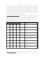
1.9 SPECIFICATIONS
This
paragraph
provides
the
operating
characteristics
and
specifications useful to a service technician for maintaining the
ATARI 400/800 Computer Console systems. All specifications and
characteristics are presented in Tables 1-1 and 1-2.
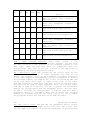
Table 1-1. ATARI 400 Computer Console Specifications
Console:
FCC approved with built-in RF m odulator.
CPU:
6502B Microprocessor; 1.78 MHz clock.
Color:
16 colors, each with 8 intensities.
Sound:
Four independent sound synthesizers for musical tones
or
game sounds, four octaves. Variable volume.
Internal speaker (in addition to audio through
television set).
Memory:
8K bytes of Random Access Memory (RAM) is included.
The ATARI 400 may be expanded to 16K at your service
center. lOK bytes ROM Operating System, expanded to
16K
with
user
installed
solid-state
Program
Cartridges.
Keyboard:
57 alphanumeric keys plus 4 function keys. Upper/
lower ca se, Inverse video. Full screen editing.
Four-way cursor control with 29 keystroke graphics.
ATARI Personal Computers
1-11
Table 1-1. ATARI 400 Computer Console Specifications (continued)
I/O: Serial input/output port for simple connection to
peripherals. Four controller jacks for joystick and paddle
controllers.
Lanquage: ATARI BASIC 8K ROM Program Cartridge is included.
Display:
Highest graphics resolution 320x192, 24 lines of 40
characters.
Power:
AC step-down transformer. UL approved.
Dimensions: 13.5 x 11.5 x 4.5 inches. 5.75 pounds.
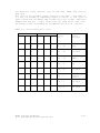
Table 1-2. ATARI 800 Computer Console Specifications
Console:
CPU :
Color:
FCC approved, with built-in RF modulator. Connects to
any television set.
6502B Microprocessor, 1.78 MHz clock
16 Colors, each with 8 intensities.
Sound:
Four independent sound synthesizers for musical tones
or game sounds, four octaves. ; ; Variable volume.
Internal speaker (in addition ; ; to audio th rough
televis ion se t). ; ;
Memory :
8 or 16K bytes of Random Acces s Memory (RAM) is
included. The ATARI 800 Console may be expanded to 48K
RAM with user-installed 8K or 16K ATARI Memory
Modules. The 800 Console includes a lOK ROM Operating
System. ROM may be expanded to
26K with userinstalled Program Cartridges.
Keyboard:
57 full-stroke alphanumeric keys plus 4 function keys.
Upper/lower case. Inverse video. Full screen editing.
Four way cursor control with 29 keystroke graphics.
I/O:
Serial input/output port for simple connection to
peripherals.
Four controller jacks for joystick and
paddle controller and light pen.
Language : ATARI BASIC 8K ROM Program Cartridge included.
Display:
Power:
Highest graphics resolution 320 x 192. 24 lines x 40
characters.
Three text modes.
AC step-down transformer. UL approved
Dimensions: 16 x 12.5 x 4.5 inches. 9.75 pounds.
1-12
System Service Manual
CHAPTER
2
INSTALLATION
-
ATARI
400/800
COMPUTER
CONSOLES
2.1 INTRODUCTION
The following paragraphs provide instructions on unpacking, system
set-up and check-out, adding peripheral devices,and repacking for
shipment.
2.2 UNPACKING
The ATARI 400/800 Computer Systems are a series of components which
function together with the user's television set to form a single
computer system.
The basic system consists of the following:
•
Computer Console
•
TV Switch Box
•
AC Power Adapter
•
2 Instruction Manual
Operators Manual
ATARI BASIC
•
Program Cartridge
•
ATARI Educational System ATAR I BAS IC La nguage
•
Ring Binder and Warranty Registration
Other configurations of the "basic" system are being put together at
ATARI. Call or write ATARI for the latest information.
Remove the accessory tray from the packing box and check that it contains all of the standard compone nts, see above. Remove the Console
with the foam end caps from the box. Remove the foam end caps and
polyethylene bag from the console. Save all your ATARI Console packaging materials for repacking and storage.
Inspect the Console and the accessories for any obvious shipping
WARNING!!
Keep all polyethylene bags away from small children!
ATARI Personal Computers
2-1
damages. If damage is found, note it on the waybill and require the
delivery agent to sign the waybill. Notify the transfer company immediately and submit a damage report to the transfer company. Be sure
to save the packing material for the transfer company's inspection.
2.3 CONNECTING THE TV SWITCH BOX
The TV Switch Box is designed to be permanently attached to the
user's television set and has an adhesive backing to hold it in place
on a smooth clean surface.
Disconnect the present antenna leads from the VHF terminals on the
back of the television set. Notice whether the antenna cable is the
round, 75 Ohm variety with a screw-on connector or the flat, twinlead 300 Ohm cable. Attach it to the matching 75 or 300 Ohm connector
labeled ANTENNA on the side of the TV Switch Box.
Attach the short, flat, twin-lead 300 Ohm cable labeled TV on the
bottom of the TV Switch Box to the VHF screw terminals on the
television. If the television antenna is of the 300 Ohm variety, the
TV Switch Box is installed.
If the television antenna is 75 Ohms, convert the television to
accept the 300 Ohm signal from the TV Switch Box. Refer to Figure 2-1
for instructions on how to convert the television to 300 Ohm antenna
input impedance.
When the COMPUTER - TV switch on the TV Switch Box is in the COMPUTER
position the television receives the RF signals from the ATARI Computer Console. Tune the television to channel 2 or 3, whichever is
weaker in your area. When the switch in the TV position, signals come
from the television antenna.
NOTE
Federal Communications Commission Require that you:
•
•
•
Avoid using any longer twin-lead wire from the TV Switch Box to the
television than that supplied with the TV Switch Box.
Avoid connecting the twin-lead wire from the TV Switch Box to any
te levis ion antenna or cable TV outlet.
Avoid attaching loose wires to the antenna terminals when the ATARI
Personal Computer products.
Any of the above may cause interference to nearby television sets and
is against Federal Communications Commission (FCC) regulat ions.
2-2
System Service Manual
Figure 2-1. Conversion to 300 Ohm Antenna Input Impedance
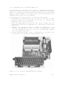
2.4 CONNECTING THE PROGRAM CASSETTE RECORDER
The ATARI 410 Program Cassette Recorder resembles an ordinary audio
cassette recorder. Its playback and recording levels have been permanently set at the correct volume for use with the ATARI Computer
Consoles.
Carefully unpack the Program Cassette Recorder from its container,
careful to save all packing material for storage and shipment.
Plug the data cord (permanently attached to the recorder) into the
jack labeled PERIPHERAL on the side panel of the ATARI Console, see
Figure 2-2.
ATARI Personal Computers 2-3
NOTE
When the Program Cassette Recorder is used in conjun ction with other
peripheral devices the Program Cassette Recorder has to be plugged
into to the I/O Connector jack on the other peripheral device (daisychained).
Plug the recorder power cord into the jack labeled AC on the side of
the recorder and into an ordinary wall socket.
ATARI Personal Computers
2-3
2.5 CONNECTING THE AC POWER ADAPTER
The AC Power Adapter supplies low voltage (9V AC) required by the
Main Power Switch on the side of the the Consoles. Check to see that
the computer consoles is OFF. Plug the AC Power Adapter into any 115
Vac outlet (ordinary house current). Plug the end of the AC Power
Adapter cable into the jack labeled POWER IN on the side panel of the
computer console, see Figure 2-2.
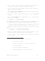
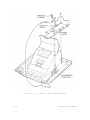
2.6 INSERTING PROGRAM CARTRIDGES
ATARI Program Cartridges contain programs that are permanently stored
in a ROM within the cartridge. To insert a Program Cartridge open the
Cartridge Door by depressing the lever marked PULL OPEN on either the
400 or 800 Consoles, see Figure 2-3. The door is held under tension
and should spring open. Hold the cartridge with the label toward you
so that it can be read. Push it firmly, straight down, into the slot.
It will snap gently into place. Single cartridges should always be
inserted in the left slot. They will be labeled LEFT CARTRIDGE on the
end opposite the opening. Double cartridges will be labeled LEFT CARTRIDGE and RIGHT CARTRIDGE. Insert them in the correct slot.
NOTE
The cartridge door containa a power interlock. In order to
preventdamageto the computer or the program cartridge, the
power is turned of f whenever the cartridge door is opened.
When the Program Cartridge is in correctly, the cartridge door will
close without touching the program cartridge.
2.7 CONNECTING TELEVISION MONITOR
The ATARI 800 Computer Console has the option of using a television
Monitor without the standard RF input cable, contains a monitor jack,
see Figure 2-2, which accepts the optional monitor cables available
from ATARI. Refer to Chapter 1, para. 1.8, Optional Equipment for the
model number of the monitor cables. Plug the monitor cable into both
the Console and the television monitor.
2-4
System Service Manual
Figure 2-2. ATARI 400/800 Computer Consoles, Side View
ATARI Personal Computers
2-5
Figure 2-3. 400/800 Consoles, Cartridge Door Open
2-6
System Service Manual
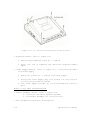
2.8 CONNECTING THE ATARI 810 AND 815 DISK DRIVE
The ATARI
of ATARI
(minimum)
four disk
810 and 815 Disk Drives may be used with many combinations
devices. However, the ATARI 800 Computer Console with 16K
of RAM memory is required to operate the disk system. Up to
drives may be connected to the system at a time.
Setting up the Disk Drive (Refer to Figure 2-4)
•
•
•
•
•
•
First verify that all switches (computer power and disk drive) are
OFF.
Plug AC Power Adapter into the wall plug, and its small plug into
the disk drive.
Plug one end of the CX 81 Data Cord furnished with the disk drive
into the plug labeled PERIPHERAL on the Console, and the other end
into either of the I/O CONNECTOR jacks on the back of the disk
drive unit.
Additional peripheral devices can be connected by using the unused
I/O CONNECTOR jack on the back of the disk drive.
If only one disk drive is to used, set the device code switch on
the back of the disk drive to position number 1. (See diagram on
back of drive).
If more than one disk drive is to be used, the switches should be
appropriately set. Yo u may find it useful to label the disk
drives by number for easy location of a particular unit.
NOTE
The device switch on each drive is normally set to 'position 1'
before shipment.
2.9 CONNECTING THE ATARI 820 AND 822 PRINTER
The ATARI 820 and 822 Printers provide 40 column printouts for the A
TARI 400 a nd 800 Personal Computer Systems.
Setting up the Printer (Refer to Figure 2-5)
•
•
•
Plug the power cord (permanently connected to the printers) into a
110-115 Vac outlet (with the Power switch OFF).
Plug the CX81 Data Cord in the serial I/O port. labeled PERIPHERAL
on the Console, or if another peripheral is in use, into the jack
labeled I/O CONNECTOR on that peripheral. Plug the data cord into
either jack labeled I/O CONNECTOR on the printer.
Inspect the ribbon (model 820) and paper for proper positioning and
useability, refer to the operator' s manual for the individual
printer.
ATARI Personal Computers
2-7
Figure 2-4. ATARI Disk Drive Cable Connections
CAUTION
Do not operate the printer without ribbon or paper or you
may damage the printer mechanism.
2.10 USING THE ATARI 850 INTERFACE MODULE
The ATARI 850 Interface Module expands the interface capabilities of
the ATARI Personal Computer Systems. The interface module connects to
the ATARI 400 and 800 Computer Consoles via an I/O CONNECTOR port
(two provided) and has four EIA RS232C compatible ports, an 8-bit
parallel output interface for connection to the ATARI 825 80 Column
Printer. Any of the serial ports can be used with the ATARI 830
Acoustic Modem. Refer to Figure 2-6 when connecting each of the
following devices.
2.10.1 Connecting the ATARI 850 Interface Module
The following steps detail the connection of the ATARI 850 Interface
Module to the ATARI 400/ 80 0 Computer Consoles :
•
•
Verify that the Power switch is OFF.
Plug the AC Power Adapter into an AC outlet (wall plug. 115Vac
nominal) and then plug the other end into the power recepticle on
the interface module.
2-8
System Service Manual
Figure 2-5. ATARI 40 Column Printer Cable Connections
•
Plug one end of the CX81 Data Cord provided into the plug labeled
PERIPHERAL on the Console~ and the other end into either of the
jacks labeled I/O CONI~ECTOR on the side of the interface module.
•
Disk drives or other peripheral devices that normally plug into
the Console PERIPHERAL jack can now be plugged into the second I/O
CONNECTOR port on the interface module.
•
Proceed with the connection of additionai peripheral devices before
applying power (Power switch ON) to the interface module.
2.10.2 Connecting the ATARI 825 Printer
The ATARI 825 Printer is an 80 column dot matrix printer that must be
connected to the ATARI 850 Interface Module. The printer connects to
the 8 bit parallel output interface port on the interface module
using the CX86 Printer Cable. Connect the printer as follows:
Check that the Power ON/OFF switch is in the OFF position.
•
Plug the CX86 Printer Cable into the parallel I/O port labeled
PARALLEL CONNECTOR on the interface module and the I/O CONNECTOR
port on the back of the printer.
•
Plug the Power Cord into a wall outlet (115 Vac nominal).
•
Refer to ATARI
procedures.
825
ATARI Personal Computers
Operator's
Manual
for
the
proper
power-up
2-9
Figure 2-6. ATARI 850 Interface Module Cable Diagram
2.10.3 Connecting the ATARI 830 Acoustic Modem
The ATARI 830 Acoustic Modem is a stand-alone acoustically coupled,
frequency shift keying (FSK) modem. It must be connected to the ATARI
400/800 Computer Consoles with the ATARI 850 Interface Module.
Connect the acoustic modem as follows:
•
Check to see that the Power ON/OFF switch is in the OFF position.
•
Plug the CX87 Modem Cable into one of the RS232C Interface ports
on the ATARI 850 Interface Module, and into the I/O CONNECTOR port
on the ATARI 830 Acoustic Modem.
• Plug the AC Power Adapter into a wall outlet (115 Vac nominal) and
plug the power cable into the power receptacle on the acoustic
modem.
•
Refer to the ATARI 830 Acoustic Modem Operator's Manual
information on proper set-up and operation of the modem.
ATARI Personal Computers
for
2-10
CHAPTER 3 - SYSTEM OPERATION
3.1 INTRODUCTION
This chapter will cover the procedures required for system power-up,
using the keyboard and screen editor functions, using Program Cartridge system keys, operating the hand controllers, and operating the
ATARI 410 Program Cassette Recorder.
3.2 SYSTEM POWER-UP
Two modes of system power-up exist for the ATARI 400/800 Personal
Computer Systems; power-up with disk drives and power-up without disk
drives. Before continuing with system power-up ensure that you have
unpacked and set-up your system according to the instructions
outlined in Chapter 2, System Installation.
3.2.1 System Power-Up Without Disk Drive
The following steps detail the procedures required to power-up an
ATARI 400 or 800 Personal Computer System without an attached Floppy
Disk Drive. These procedures assume that the system has been set-up
according to the instructions contained in Chapter 2, System
Installation.
Without Program Cartridge.
To power-up the system without a Program Cartridge requires only that
the system be connected to all devices correctly, and the System
Power-ON switch is set to ON. After a few seconds, the screen will
display the "ATARI COMPUTER - MEMO PAD" logo. The Memo Pad Logo
indicates that the system has run a self-test, with no failures, and
is ready to accept information from the Keyboard.
With Proqram Cartridge.
To power-up the system with the Program Cartridge installed, requires
only that the system be connected to all devices correctly, and the
System Power-ON switch is set to ON. After a few seconds, the screen
will display a prompt depending upon the Program Cartridge, ie., the
BASIC Cartridge prompts you with a "READY" written on the screen.
Some Program Cartridges might require you to press the START key or
load a program from the Program Cassette Recorder. The screen display
will prompt you with the correct action for you to take.
ATARI Personal Computers
3-1
Before 'loading' the program contained on the Program Cartridge the
Console Operating System, contained in ROM, has already run a self
test and found the system to be operating properly.
Anytime the Cartridge Door is raised to change the Program Cartridge
or add/remove a cartridge, the system Interlock switch shuts off
power to the Console. The power automatically returns when the door
is shut, and the system repeats the power-up sequence (in the process
clearing all information stored in RAM Memory).
3.2.2 System Power-Up With Disk Drive
The system power-up sequence with an attached Floppy Disk Drive
requires more attention to following the exact sequence of instructions. The following procedures assume that the system has been connected according to the instructions outlined in C hapter 2, System
Installation.
Proceed as follows:
1. Connect the system devices according to the instructions outlined
in Chapter 2.
2. Power-up the peripheral devices according to the instructions in
their respective Operators Manuals.
3. When the Busy Light turns O FF, insert the Master Diskette (Disk
File Manager) into the Floppy Disk Drive no. 1, and close disk
door.
4. If applicable insert the Program Cartridge in the Cartridge slot.
and close Cartridge door.
5. Set the System Power switch to ON. The system automatically
'boots' the program from the Master Diskette.
6. The prompt that appears on the screen will depend upon the Program
Cartridge or lack of Program Cartridge. The BASIC Program Cartridge will display the 'READY' prompt. Entering 'DOS' on the
Keyboard will display the Disk Operating System Menu.
8. Once the Disk File Manager has been read from the Master Diskette,
the Master Diskette can be removed from the Floppy Disk Drive. The
program now resides in RAM memory.
3.3 KEYBOARD AND SCREEN EDITOR FUNCTIONS
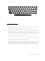
The ATARI Personal Computer Keyboard, see Figure 3-1, closely resembles an ordinary typewriter, but has been designed with additional
flexibility to provide the ATARI user with the most efficient set of
symbols for each Computer Console application. In addition, each key
has the capacity
3-2
System Service Manual
to be redefined by
Cartridge or program.
instructions
from
an
individual
-
Program
The following paragraphs define the use and application of each of
the keys.
Figure 3-1. The ATARI Keyboard
•
•
•
•
•
•
CAPS/LOWR - Pressing this key once, puts the Keyboard in the
uppercase/lowercase mode, requiring the use of the SHIFT key to get
uppercase letters and special characters. Pressing the key once
again, puts the Keyboard in the all uppercase mode.
SHIFT - Pressing either of the SHIFT keys and holding it down
(while in the lowercase mode) while pressing another key will
produce the uppercase letters or the character shown on the upper
half of the keytop on the actual keyboard. Figure 3-4 shows the
characters that will be produced by the SHIFT and key combination
ATARI LOGO - The ATARI Logo key switches characters into inverse
video. Press it again to go back to normal display.
CTRL - The control key CTRL functions as a second type of shift.
When depressed in conjunction with another key a completely new set
of graphics appears on the screen. Figure 3-2 shows what the
combination of the CTRL key and other keys will produce on the
screen.
ESC - The ESC (escape) key disab les the cursor control movements
and prints a graphic character on the screen instead. Figure 3-3
shows what the combination of the ESC key and o ther keys displays
on the screen.
BREAK - The BREAK key interrupts the computer while it is busy
following instructions.
ATARI Personal Computers
3-3
Figure 3-2. Special Graphics Using the CTRL Key
• RETURN - The RETURN key has three functions. First, if moves the
cursor to the left margin and down one line on the screen. Second,
RETURN marks the end of a logical line for the computer. Third,
RETURN activates the computer. The specific action taken depends on
the software.
• CLR-SET-TAB - This key operates much like the TAB key on a regular
typewriter. SHIFT and CLR-SET-TAB set a TAB stop at the cursor
position. CTRL and CLR-SET-TAB clear the TAB stop u nder the
cursor. CLR-SET-TAB by itself spaces the cursor over to the next
TAB stop. This key operates on logical lines so you can tab at any
position up to the 116 th character.
3-4
System Service Manual
Figure 3-3. Special Graphics Using the ESC Key
ATARI Personal Computers
3-5
Figure 3-4. SHIFT Keyboard and Key Combination
Screen Editinq Functions
•
SHIFT CLEAR or CTRL CLEAR - When held down simultaneously erases
all characters on the screen and moves the cursor to the home
position at the upper left corner of the screen.
•
CTRL and the UP arrow, DOWN arrow, RIGHT arrow, LEFT arrow - These
cursor control functions move the cursor on the screen in the
direction shown by the arrows on the keytops. When you move the
cursor over a letter, that letter is shown in inverse video on the
screen. When you move the cursor away from it using the cursor
controls the letter is unchanged. If you put the cursor over a
character, and then push another character key, the new character
will replace the one previously shown.
•
SHIFT and INSERT - This combination of keys creates a space for a
new line by rnoving the logical line containing the cursor and all
lines below it down one line. The information on the bottom line
of the screen that is pushed off will be lost.
CTRL and INSERT - This combination of keys creates a space for a
new character by moving the character under the cursor to the
right. The rest of the line also shifts to the right. The cursor
remains on the space which is now available for the new character.
•
3-6
System Service Manual
•
•
•
DELETE BACK S - This key erases each character as the cursor moves
back one space at a time. The whole line stays the same length.
SHIFT and DELETE BACK S - This combination of keys removes one
whole logical line. If there are lines below the deleted line they
will all move up one line leaving a new blank line at the bottom
of the screen.
CTRL and DELETE BACK S - This combination erases the character
under the cursor by moving all the characters to the right of the
cursor one space to the left. The line becomes shorter.
3.4 PROGRAM CARTRIDGE SYSTEM KEYS
The four keys to the right of the Keyboard allow the operator to
select different starting positions within a Program Cartridge. Each
starting position is the beginning of a game or application stored
within a single Program Cartridge.
Push SYSTEM RESET to stop the computer and restart from the beginning
of a Program Cartridge. Push SELECT to see the initial screen at the
beginning of the next game or application. Push OPTION to choose
among the variations possible within a game or application. After you
have made your choices with the SELECT and OPTION keys, push START to
begin the action.
3.5 OPERATION OF HAND CONTROLLERS
Many of the Program Cartridges available from ATARI use the Hand
Controllers to move images on the display screen. All hand
controllers are identical and can plug into any of the Controller
jacks on the front of the Consoles. Each Hand Controller has one
button and eight possible stick positions. The "stick" or "paddle"
can be moved in a 360 degree circle and can be used by the program to
position the screen.
3.6 ATARI 410 PROGRAM CASSETTE RECORDER
The ATARI 410 Program Cassette Recorder resembles an ordinary audio
cassette tape recorder. Its playback and recording levels have been
permanently set at the correct volume for use with the ATARI Personal
Computers. Set up the 410 Program Cassette Recorder according to the
instructions contained in Chapter 2, System Installation.
3.6.1 Operation of the Program Recorder
The following steps explain the use of each of the control keys on
the program recorder.
ATARI Personal Computers
3-7
•
Press STOP
cassette.
•
Insert a cassette into the aperture, with the tape surface toward
you and close door.
•
Press REWIND to move to the beginning of the tape (the tape will
stop automatically at end of tape, press STOP EJECT once to
disengage REWIND).
Press the tape COUNTER reset button until the counter shows 000. As
the tape advances, this counter will show the approximate location
on the cassette tape. Use this number to find programs stored in
the middle of the tape. Before storing a program beyond the
beginning of a tape, note the counter number for later reference.
•
EJECT
to
open the
cassette
door and
disengage
the
•
Press ADVANCE to move tape forward to the location of a program
(indicated by the Tape Counter) if necessary, then press STOP
EJECT.
•
Press PLAY to ready the recorder for starting signal from computer.
NOTE
Do not press the ADVANCE key while rewinding the cassette tape,
also do not press the REWIND key while advancing tape, either
action will stretch the casette tape.
3. 6. 2 Transfer a Program to Cassette Tape
The following steps detail the procedures required to transfer programs from the Computer Console RAM memory to the Program Recorder
cassette tape. (Refer to the BASIC Reference Manual for additional
command information):
1. Insert a blank cassette tape into the Program Recorder with the
recording surface toward you and the label so that it can be
read. (Side one of the cassette tape will now be recorded on, to
record on side two of the cassette tape, turn tape over and
reinsert).
2. Press REWIND and wait until the tape stops.
3. Press the Tape Counter Reset button until it reads 000.
4. Press STOP EJECT once (not hard enough to eject tape).
5. On the Computer Console Keyboard type: CSAVE, RETURN. You will
hear two beeps.
6. Press RECORD and PLAY simultaneously on the Program Cassette
3-8
System Service Manual
Recorder. Now press RETURN on the keyboard again. A series of
tones indicates that the Program Recorder is under control of the
Computer. The Program Recorder will erase the beginning of the
tape surface for approximately eighteen seconds, and copy the program from RAM onto the cassette tape, then stop.
7. To record more than one program on a cassette tape repeat steps 5
and 6 until all programs are recorded. Be sure to record the
starting tape counter number for each of the programs recorded.
NOTE
It is good programming technique to create a backup cassette tape for
each of your recorded cassette tapes.
8. Press STOP EJECT on the Program Recorder.
3.6.3 Transfer a Program from Tape to Computer
The following steps detail the procedures required to transfer a program recorded on a cassette tape to the RAM memory of a Computer Console.
1. Insert the prerecorded cassette tape into the Program Recorder
with the recording surface toward the front and the label so that
it can be read.
2. Press REWIND and wait until the tape stops.
3. Press STOP EJECT once (not hard enough to eject cassette).
4. Press the Tape Counter Reset button until it reads 000.
5. Use the ADVANCE key to position the cassette tape at the beginning
of the stored program (refer to record you made in step 7, above).
6. On the Computer Console keyboard type: CLOAD and press RETURN. You
will hear one beep.
7. Press PLAY on the Program Recorder. Then press RETURN on the keyboard. A series of tones from the computer indicates that the
program is being transferred.
8. When the tape stops, the program has been transferred from the
cassette tape to the computer.
9. Press STOP EJECT on the Program Recorder.
ATARI Personal Computers
3-9
CHAPTER 4. FUNCTIONAL DESCRIPTION
4.1 INTRODUCTION
The following paragraphs provide a fuctional block diagram discussion
of the ATARI 400 and 800 Computer Console Systems. The first
paragraphs will describe the overall system, using a simple block
diagram discussion of the major fuctional modules. Later sections
provide a more detailed discussion of each of these major functional
modules.
For greatest convenience, all the Figures referred to in this Chapter
have been placed together at the end of the Chapter.
4.2 The ATARI 400 and 800 Computer Console Systems
The ATARI 400 and 800 Computer Consoles are made up of seven major
functional modules. Refer to Figure 4.1.
•
•
•
•
•
•
•
Motherboard
CPU Printed Circuit Board
ROM Personality Printed Circuit Board (Operation System)
RAM Memory Printed Circuit Board
Keyboard
Power Supply
Program Cartridges
The printed circuit boards plug into sockets on the Motherboard,
utilizing a common Address Bus, Data Bus, and clock lines. The
various power requirements are routed from the Power Supply through
the Motherhoard to all the printed circuit boards. The Keyboard
connects directly to the Motherhoard through a ribbon oonnector. The
sixteen-Line Address bus (AO-A15) allows the microprocessor to
directly address 65,536 (64K) memory locations. The eight line Data
bus (DO-D7) provides the communication and data path beween the
various functional modules.
4.2.1 Motherboard
The Motherboard perfoms the function of tying together all the
various components of the computer system, as well as performing a
variety of logic fumctions. All printed circuit boards, (pcb) and
connector cables plug into the Motherboard to allow communication
between the functional blocks of the 400 and 800 Computer Consoles.
The Motheraoard also does the following:
ATARI Personal Computers
4-1
•
Generates 3.58 MHz Master Clock for the CPU printed circuit
board.
•
•
Generates Power-On Reset for the CPU printed circuit board.
Performs parallel/serial data conversion between the CPU
printed circuit board and the peripherals.
•
Provides driving circuitry for the Key-Press signal from the
CPU printed circuit board to the Console Speaker.
•
Converts signals from the various hand
recognizable data for the microprocessor.
•
Buffers and drives the data lines between the CPU printed
circuit board, the RAM Memory pcb(s), and the remainder of
the system.
•
Performs the first Memory Map decoding of the possible 64K
address locations to 8K blocks for the microprocessor.
•
Generates control signals for the peripheral devices.
•
Receives video data from the CPU printed circuit board,
converts it to a composite video and routes it to the Power
Supply pcb.
•
Combines the sound from the computer system and the audio
track of prerecorded cassettes.
•
Develops the sound subcarrier for the television audio as
part of the composite video.
controllers
into
4.2.2 Central Processing Unit
The Central Processing Unit (CPU) printed circuit board (pcb)
performs the function of controller for the entire Console system.
The CPU pcb contains the 6502 Microprocessor, the ANTIC chip (a
specialized microprocessor) and the CTIA chip, which generates the
video signals for the system. The CPU pcb controls the Console system
and its peripheral devices through address lines (to select which
device it needs to communicate with) and data lines (to transmit or
receive data from a selected device) common to the entire system.
Operating instructions for the microprocessor come from the ROM
Operating System on the Personality pcb. Additional functions of the
CPU pcb are:
4-2
System Service Manual
•
•
Receives Master Clock from Motherboard and generates Phase 1 (Φ1
or Ph 1) and Phase 2 (Φ2 or Ph 2) clocks used to synchronize the
entire system.
Transmits "Refresh" signal at least every 2 milliseconds to refresh
the dynamic RAM memory chips on the RAM Memory pcb.
•
Receives the four "trigger" lines from the fire button of the hand
controller accessories.
•
Receives the lines from the four control switches to the right of
the Keyboard:
Option - Selects a variation of the Program Cartridge
Select - Selects a different portion of the Program Cartridge
Start - Starts a program (usually on the Program Cartridge)
System Reset - Resets the system
•
Generates video signals to be processed by the Motherboard before
being sent to R.F. Module on the Power Supply pcb.
4.2.3. ROM Personality pcb
The ROM Personality pcb contains in read-only memory (ROM), the
program of operating instructions for the microprocessor. Two 4K ROMs
contain the Operating System, and one 2K ROM contains arithmetic
functions for use with BASIC programming. Information is retreived
from the ROMs by addressing a particular location on the ROM using
the Address bus. The data contained in that location is placeed on
the Data Bus to be read by the microprocessor.
The ROM Personality pcb also provides the Chip Select signals used to
select the various LSI chips throughout the Console system and for
the bidirectional data buffers on the Motherboard.
4.2.4 RAM pcb
The RAM (Random Access or Read/Write Memory) pcb performs the
function of temporary data storage for the System. The RAM is dynamic
RAM, requiring refresh, and comes in 8K or 16K versions.
Each RAM chip on the RAM pcb has only seven address lines. To address
16K separate locations requires fourteen address lines. To accomplish
this, a fourteen-bit address is sent to the address demultiplexer,
which first passes the lower seven bits to the RAM chips as a Row
Address.
ATARI Personal Computer
4-3
After an appropriate delay, the highest seven bits are passed as a
Column Address. Data is then either put in or taken out of the
location selected. Direction of data flow is determined by the
Read/Write line.
Refresh occurs at least every 2 milliseconds. The refresh signal is
generated on the CPU printed circuit board.
4.2.5 Keyboard
The keyboard generates alphanumeric characters as well as special
graphic symbols. The keyboard allows the operator to communicate with
the
Console
system
for
writing
programs
or
responding
to
preprogrammed cassettes or cartridges. The keyboard consists of
fifty-seven normally open switches. They are scanned at a rapid rate
and when a switch is found closed, that scan pattern is sent to the
microprocessor for encoding.
4.2.6 Power Supply
The Power Supply printed circuit board receives 9 Vac from an
external power adapter (transformer) and provides +5 Vdc, +12 Vdc,
and -5 Vdc for the Console system. The Power ON/OFF switch is mounted
on the Power Supply pcb and removes input power by opening the 9 Vac
line. An additional interlock switch removes power from the system
when the operator opens the top panel to install or remove Program
Cartridges.
The RF Module also resides on the Power Supply pcb. The RF Module
generates the RF output for the video screen from the composite video
signals received from the Motherboard, and is switchable to
television channel 2 or 3.
Voltages:
+5 Vdc A - Supply voltage for the logic pcbs
+5 Vdc B - Specially filtered for the video circuitry
+12 Vdc and -5 Vdc - Supply voltage for the dynamic RAM memory chips
4.2.7 Program Cartridge
The Program Cartridge performs the function of permanently storing
the microprocessor instructions for a particular application, e.g., a
game or
check book balancing program. It consists of two 4K ROM chips mounted
on an enclosed printed circuit board. Information is retreived from
the ROM chips by addressing the memory locations assigned to the
Program Cartridge slot(s). The data in the memory locations is then
placed on the Data bus lines.
4.3 FUNCTIONAL BLOCK DIAGRAM DISCUSSION
The following paragraphs provide a detailed functional block diagram
discussion of the 400 and 800 Console Systems.
4-4
System Service Manual
4.3.1 Central Processing Unit Board (CPU Board)
The Central Processing Unit (CPU) pcb contains the 6502 CPU (or MPU)
CHIP (A303), the CTIA chip (A301), the ANTIC chip (A302), tri-state
address buffers (Z303 & Z304), and the Clock Generator (Z302A and
Z302B). See Figures 4-2 and 4-3.
CPU 6502 Integrated Circuit. The 6502 microprocessor contains
registers flags, interconnections, arithmetic logic, and control
logic which recognize operation codes. The salient characteristics of
the 6502 microprocessor are summarized as follows:
•
Byte-oriented structure
•
•
•
•
•
•
•
•
151 opcodesDecimal or binary arithmetic modes
Seven addressing modes
True indexing
Stack pointer
Two interrupt levels
64K address range
Integral clock circuit
Single 5-volt dc power requirement
Figure 4-3 shows pin assignment of the
functions of the pins are given below.
6502
microprocessor.
The
AB0-AB15 Address Bus. The Address Bus signals on the 6502 MPU are
push-pull drivers capable of driving one standard TTL load and 130
picofarads of capacitance. The address placed on the Address Bus is
determined by the Program Counter in the 6502 MPU or a stored address
in RAM memory, specified by the program instruction. The ANTIC chip
also puts addresses on the system Address Bus, sharing control of the
bus with the 6502 MPU.
DB0-DB7 Data Bus. Pins 26 through 33 are connected to the
bidirectional Data Bus. Each of these pins is connected to both an
input and an output buffer. The output buffer is in three-state high
impedance (isolated)
condition except when data transfer out takes place. All data
transfers take place during the Phase 2 clock pulse. During Phase 1
the Data Bus is in the isolated high impedance condition. The Data
Bus output buffer is a push-pull driver, like the Address Bus driver,
and is capable of driving a TTL load. The data on this bus from an
external support chip must be stable before the end of the Phase 2
clock pulse.
ATARI Personal Computers
4-5
R/W Read/Write. The R/W Line allows the microprocessor to control the
direction of data transfer among system components. When the voltage
level is high the R/W line is reading from the Data Bus into the
microprocessor. When the voltage level is low it is commanding an
external device to write the present contents of the Data Bus into a
peripheral support chip or memory. All transitions on this line occur
during Phase 1, which allows control of data transfers during Phase
2.
RDY - Ready. The RDY input permits delay of execution of any machine
cycle during which the RDY line is held low. If the Ready (RDY) line
goes from high to low during a Write cycle the processor will execute
that cycle and will stop in the next Read cycle.
SYNC - Synchronzing Signal. The SYNC signal is an output signal
produced when the 6502 microprocessor is fetching an opcode. This
line goes high during Phase 1, and stays high for the remainder of
the cycle. If the RDY line is pulled low during Phase 1 of a SYNC
high cycle, single-step operation of the 6502 microprocessor can be
achieved.
SO - Set Overflow. The SO line is an output line that sets the
Overflow bit in the Status Register. The Overflow bit is set to a
logic one {high) on a high to low transition on this pin.
RES - Reset. The Reset line is used to initialize the microprocessor
during power-up. As the Power Supply is turned on the RES line is
held low, resetting internal registers. When the line goes high the
processor will delay six Phase 1 to Phase 2 cycles. After the RES
delay the processor will fetch instructions from memory locations
FFFC and FFFD.
NMI - Non-maskable Interrupt. The Non Maskable Interrupt (NMI) input
interrupts the processor after it has completed the instruction being
executed when the NMI line was pulled low. The NMI interrupt cannot
be masked by the processor to prevent recognition of this interrupt.
The processor will not detect another NMI until this line has gone
high and then back to low. The NMI signal must be low for at least
two clock cycles in order to be recognized. The following steps take
place when an NMI signal is recognized:
•
•
•
The values in the Program Counter and the processor Status register
are pushed on the stack into three successive locations determined
by the value of the stack pointer when NMI is detected.
Locations FFFA and FFFB will be read to vector the processor to a
subroutine to handle the interrupt.
The Interrupt mask in the processor Status register is set to a
one, disallowing a maskable interrupt.
The microprocessor will be returned to its original condition upon
reading a RTI instruction in the interrupt handler subroutine.
4-6
System Service Manual
IRQ - Interrupt Request. The IRQ request input is similar to the NMI
signal. Unlike the NMI signal, the IRQ input can be controlled by bit
2 of the Program Status register, the interrupt mask bit {I). If the
flag bit I is a logic one, signals on the IRQ input will be
disregarded. The IRQ line is level-sensitive, not edge-sensitive. The
processor will be interrupted as long the flag bit I is low and IRQ
is low. The processor performs the same steps as an NMI operation,
with different locations for the vector address (FFFE and FFFF). The
processor will be returned to its original condition upon reading a
RTI instruction in the interrupt handler subroutine.
ANTIC and CTIA Integrated Circuits.
The primary function of the ANTIC integrated circuit is to fetch data
from memory, independent of the processor, for display on the video
screen. Direct Memory Access (DMA), is used by the ANTIC chip to
retreive data from memory. The ANTIC chip requests the use of the
Address Bus and the Data Bus by sending a HALT signal to the
microprocessor, causing the processor to become "Tri-State" during
the next computer cycle. The ANTIC then addresses and reads from
memory the data for placement on the video screen. Once initiated,
the DMA is completely and automatically controlled by the ANTIC chip
without need for further microprocessor intervention.
In addition to the display DMA, the ANTIC chip also generates DMA
addresses for the refresh (REF signal) of the system dynamic RAM
memory. The ANTIC chip steals cycles from the 6502 processor to do
memory refresh and fetch graphics data when needed. Each byte of data
fetched from memory requires one machine cycle. Memory refresh takes
nine cycles out of every video display line, unless pre-empted by a
high resolution graphics mode. Memory refresh continues during
vertical blank. Once memory refresh starts on a line, it occurs every
four cycles unless pre-empted by DMA.
Graphics data retreived from memory, via the ANTIC DMA process, is
routed to the CTIA graphics registers. A color-luminance register is
contained on the CTIA chip and as the serial graphic data passes
through the CTIA chip it is "impressed" with color and luminance
values contained in these registers, before being sent to the video
display. Priority is assigned to all objects by the CTIA chip before
the serial graphics data is sent to the video display.
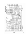
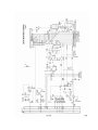
4.3.2 Motherboard Console System (400)
The 400 Console Motherboard contains the POKEY chip (A101), the PIA
chip (A102), the ROM Personality chips (A103, A104, A105), the
Keyboard Key-In/Key-Out analog multiplexers, the Memory Map Decoder
(Z103), the controller jacks (J101 through J104), the CPU connector
jack (J110), and the Keyboard connector jack (J105). See Figures 4-4
and 4-5.
ATARI Personal Computers
POKEY Integrated Circuit
4-7
The POKEY integrated circuit provides the interface between the
Keyboard, Serial I/O ports, and the microprocessor. Also contained
within the chip are four semi-independent audio channels, each with
its own f requency, noise, and volume control. Figure 4-6 shows pin
assignments of the POKEY chip, and the functions of the pins are
given below.
D0 - D7 Data Bus. The Data Bus lines (8 bits) are used to input and
output information between the POKEY chip and the microprocessor. The
Data Bus lines are routed to the processor through bidirectional
tristate buffers.
CS0 Chip Select. This signal originates on the ROM Personality pcb,
and is used by the microprocessor to select the POKEY chip. The POKEY
chip is selected when this line goes low.
AUD Audio Signąl. Four sound registers are located in the POKEY chip.
The output of these registers are used to develop the audio signal.
A0 - A3 Address Bus. These address lines are used in conjunction with
the Chip Select (CS0) line to address parts of the POKEY chip.
KR2. This input line is held low during the selection of certain
keys. The keys that take this line to an active low are the Break,
Control, and both shift keys.
KR1. This line goes low to indicate that a key has been found
depressed during a Keyboard scan. The value on pins K0 - K5 when KR1
goes low is sent to the microprocessor to determine the key
depressed.
K0 - K5. The value on these pins increments as the Keyboard is
scanned.
The value indicates a Keyboard key position.
P0 - P7. Two lines correspond to each of the four connector ports on
the front of the Console. Each line is an analog input into the POKEY
chip which converts this analog signal into an eight-bit binary code.
R/W - Read/Write. When R/W goes low (logic0) data is transferred from
the microprocessor Write operation) to the POKEY chip. When R/W goes
high (logic 1) data is transferred from the POKEY chip (Read
operation) to the microprocessor.
Ph 2 or Φ2 - Clock Input. Phase 2 of Master Clock is used by the
Pokey chip to generate its own internal timing.
SID - Serial Input Data. Serial Data from devices such as the Program
Recorder and the Floppy Disk Drive are input on this line.
SOD - Serial Output Data.
devices on this line.
4-8
Data is
output serially to peripheral
System Service Manual
Clocks OCLK and BCLK. These clocks are used as timing control signals
for the input and output of data.
IRQ Interrupt Request. The Interrupt Request line is used by the
POKEY chip to initiate communication with the microprocessor. Setting
this line low interrupts the processor and forces the processor to
service the POKEY chip.
Peripheral Interface Adapter (PIA).
The Peripheral Interface Adapter (6520) has two 8-bit programmable
I/O ports and two controller bits for each port, for a total of ten
lines per port. The two control lines for each port are used to
accomplish the handshaking during the exchange of data on the eight
data Iines. The external output lines are described in the following
paragraphs :
D0-D7, Data Bus. The eight-bit bidirectional Data Bus transfers data
to the PIA chip during an input operation, and to the peripheral
ports A and B during an output operation.
PA0-PA7, Port A Lines. The eight-bit peripheral port A lines are
programmed lines which can serve both input and output operations.
The data direction register determines the direction data is
transferred. A logic 1 (high) at pin CA2 specifies an output
operation and a logic 0 (low)specifies an input operation.
PB0-PB7, Port B Lines. The eight-bit peripheral port B lines are
programmed lines which can serve both input and output operations.
The data direction register determines the direction of data
transfer. A logic 1 (high) at pin CB2 specifies an output operation
and a logic 0 (low) specifies an input operation.
VCC, VSS. VCC is the
integrated circuit.
+5V dc
supply, and
VSS is ground
for the
Ph 2 or Φ2 - Phase 2 Clock. This signal is the Phase 2 clock signal
generated at the microprocessor. It is used to synchronize operations
using the Data Bus.
RSO, RS1 - Register Select. The two Register Select lines, along with
bit 2 of the Control Register and R/W bit, determine the data path
and function. Selection combinations are shown in Table 4-1.
R/W - Read/Write. This line is high for a Read operation and goes low
for a Write operation. R/W, together with 2, RS, and CS control the
operation of the PIA chip.
CS0, CS1, CS2 - Chip Selects. These inputs are used to select the PIA
chip. CS0 and CS1 must be high and CS2 low in order to select the PIA
chip.
ATARI Personal Computers
Table 4-1. PIA Register Selection and Function
4-9
RS0
RS1
RwW
CRA2
CRB2
Function
0
0
X
0
X
Read or Write
Register A
Data
0
0
0
1
X
Write into
Register A
0
0
1
1
X
Read from A-side input pins PA0 PA7
0
1
X
X
X
Read or Write Control Register A
1
0
0
X
1
Write into
Register B
1
0
X
X
0
Read or Write
Register B
1
0
1
X
1
Read from B-side input pins PB0PB7
1
1
X
X
X
Read or Write Control Register B
Peripheral
Peripheral
Data
Direction
interface
Interface
Direction
IRQA - IRQB Interrupt Requests. These lines connect to the
microprocessor IRQ line to provide interrupt requests. The IRQ lines
are open-collector so that several can be connected together to the
same input. When the PIA chip wants to communicate with the
microprocessor this line is set low. Control of the IRQ lines is
determined by the Control Registers A and B.
CA1 - CA2 Control lines. CAl and CA2 are the control lines for the
peripheral devices. CA1 is an input interrupt only from an I/O
device. The interrupt can be set by a negative or positive transition
of the input signal as determined by the Control Register A. Setting
the interrupt request line IRQA by CA1 is also controlled by CRA. CA2
can be used either as an input or output control line. In one output
mode CA2 generates a pulse each time data is read by the processor.
The pulse can be used to input sequential data. In a second output
mode CA2 is used in conjunction with CA1 to provide the "handshake"
between the microprocessor and the peripheral device. The CA1 input
is used to interrupt the microprocessor to indicate that data from a
peripheral device is available. When the processor has finished
reading the available data the CA2 output line is set low to signal
the peripheral device that new data can be made available.
4-10
System Service Manual
CB1, CB2 Control Lines. CB1 and CB2 are peripheral device control
lines. CB1 is used as an input control line only. CB1 control line
can set IRQB on a negative or positive transistion as determined by
Control Register B. CB2 can operate both as an input or output
control line. CB2 can be used in conjunction with CB1 to provide the
"handshake" between the microprocessor and a peripheral device. Each
time the microprocessor writes data to the PIA output register, CA2
control line is set high to signal the peripheral device. When the
data is read by the peripheral device it signals the microprocessor
by setting CB1 control line high.
RESET. Setting this line low resets all the registers in the PIA. It
also inhibits false outputs on the Port or Data Lines.
Input/Output Data Transfers.
The following paragraphs detail the procedures involved in typical
Input/Output operations.
Transfer of data to a peripheral device is performed by first writing
data to the PIA. The data is then put on the peripheral output line
for use by the peripheral device. The "handshake" procedure for the
output of data to a peripheral device is as follows:
1)
The microprocessor signals the peripheral device that data
isavailable on the Data Out line (SOD) by setting the CA1
control line high.
2)
The peripheral device reads the data and signals the
microprocessor that the data has been read by setting the CB
1 control line high.
3)
The microprocessor can either make new data available to the
peripheral device, and the cycle would be repeated, or the
transfer of data can be terminated.
The peripheral input port on the PIA chip is used to transfer data to
the microprocessor. The data from the peripheral device is made
available on the input Data Bus.
1)
The "handshake" procedure for the transfer of data from a
peripheral device to the input port is as follows:
2)
The CA1 line goes high to interrupt the microprocessor to
indicate that data is available on the peripheral I/O
port.The microprocessor reads the data on the input data
line (SID) on the POKEY chip.
3)
When the microprocessor has finished reading the available
data it signals the peripheral device by setting the CS2
line low.
ATARI Personal Computers
4-11
4.3.2.3 Key-IN Key-OUT Integrated Circuits. These two 4051 (Z101 and
Z102) integrated circuits are used to scan the Keyboard for input
data on the 400 and 800 Computer Consoles. The 4051 integrated
circuits are analog multiplexers controlled by the input lines A, B,
C and X. A binary count between 0 and 7 is applied to the input lines
A, B, and C (pins 9, 10, and 11) to select one of the output lines,
XO - X7. The eight possible inputs on each 4051 chip allows a maximum
of 64 keys to be scanned (the 400 and 800 keyboards both contain 57
keys). When a key is scanned and found depressed, the output line X
(pin 3) goes low to signal the POKEY chip to stop the count. The
value present on lines K0 through K5 of the POKEY chip is sent to the
microprocessor. The microprocessor uses a "look-up" table to
determine the Keyboard character depressed.
4.3.2.4 Memory Map Decoder. The Memory Map Decoder integrated circuit
(Z103) on the 400 Motherboard is a one-of-ten decoder. Four input
lines (pins 12, 13, 14, and 15) determine which output line is
selected. The 400 Console only uses three of the input lines (pin 12
being grounded) for a total of eight selected output lines (S0 - S7).
Refer to Table 4-2 for the line selected for each input combination.
TABLE 4-2. Memory Map Select Lines
Signal/Pin
Active
GND12 A15/13 A14/14 A13/15 line
Device
L
L
L
L
1 - S0
8K RAM
L
L
L
H
2 - S1
8K RAM
L
L
H
L
3 - S2
8K RAM
L
L
H
H
4 - S3
8K RAM
L
H
L
L
5 - S4
8K RAM/CARTRIDGE L, R
L
H
L
H
6 - S5
8K RAM/CARTRIDGE L
L
H
H
L
7 - S6
2K ROM
L
H
H
L
7 - S6
I/O DECODER (Z105)
L
H
H
H
9 - S7
4K ROM "E" and "F"
4-12
System Service Manual
4.3.2.5 I/O Decoder. The I/O Decoder integrated circuit (Z105) is a
one-of-eight decoder/demultiplexer. The I/O Decoder is used to select
the different output devices, such as PIA chip, POKEY chip and the
CTIA chip.
Only four of the possible output selections are used. ( See Table 43. ) The I/O Decoder is enabled by inputs on pins 4, 5, and 6; pin 4
input coming from the Memory Map Decoder (S6); pin 5 input coming the
Address Bus and pin 6 input coming from the Chip Select (CS) line.
The Binary Decode is provided by the Address Bus (A08, A09 and A10).
Table 4-3. I/O Decoder Select Lines
Enable/Pin
A
A
1
1
2
1
6
5
S
6
4
Binary
A
1
0
3
Decode
A
A
9
8
2
1
H
L
L
L
L
L
Y0 - 15
CTIA
H
L
L
L
L
H
Y1 - 14
Not Used
H
L
L
L
H
L
Y2 - 13
POKEY
H
L
L
L
H
H
Y3 - 12
PIA
H
L
L
H
L
L
Y4 - 11
Not Used
H
L
L
H
L
H
Y5 - 10
External
Select
Y6 - 9
Not Used
Y7 - 8
Not Used
ATARI Personal Computers
4.3.3 Motherboard Console System (800)
Active
Pin
Device
Selected
4-13
The 800 Console Motherboard contains the POKEY chip (A101), the PIA
chip (A102), the Keyboard Key-In/Key-Out analog multiplexers (Z103
and Z104), the I/O Decoder (Z101), Bidirectional Data Buffers (Z105
and Z106), the
controller jacks (J101 through J104), the Keyboard connector jack
(J106), the left and right Program Cartridge jacks (J108 and J109),
the CPU connector jack (J101), the ROM Personality connector jack
(J107), and the
RAM Memory connector jacks (J102, J103, and J104). See Figures 4-7
and 4-8.
Refer to the descriptions provided in paragraph 4.3.2, Console
Motherboard (400), for items similar in both the 400 and 800 Console
Motherboards. The following paragraphs will describe those items
unique to the 800 Console Motherboard.
4.3.3.1 Bidirectional Data Buffer
The Bidirectional Data Buffers (Z105 and Z106) are 74LS243 quad
transceivers, commonly referred to as tristate buffers. Tristate
refers to the three states that can occur in the device; the first
state, pin 1
going high and pin 13 staying low, allows data to flow through the
data buffer in the direction of the CPU; the second state, pin 13
going high and pin 1 staying low, allows data to flow through the
data buffer in the direction of the POKEY chip, the PIA chip and the
Personality pcb; the third state, with pin 1 and pin 13 both staying
low, creates a high impedance condition in the data buffers and
allows other devices to transmit data on the Data Bus lines. This
high impedance state also isolates the CPU and the RAM pcbs from
noise generated from a device using the Data Bus lines.
4.3.3.2 I/O Decoder
The I/O Decoder integrated circuit (Z1010) is a one-of-eight
decoder/demultiplexer. Refer to the description provided in Section
4.3.2. The I/O Decoder is the same in the 400 and 800, but is labeled
Z101 in the 800 console and Z105 in the 400 Console.
4.3.3.3 Composite Video
The 400 and 800 Motherboards route the Composite video signals (COMP
CHROMA, COMP LUM, MOD, and COMP VIDEO) to the Power Supply to build
the RF video output.
4.3.4 ROM Personality Board
The ROM Personality printed circuit board plugs into connector jack
J107 and occupies memory Iocations D800 through FFFF. The Personality
board contains the operating system on three ROM chips, two 4K chips
and one 2K chip ( See Figures 4-9 and 4-10). The two 4K ROM chips
4-14
System Service Manual
(A401 and A403) contain the I/O subsystem, interrupt processing,
initialization, Power-Up and Reset. The 2K ROM chip (A402) contains
the floating point arithmetic package.
I/O Subsystem. The I/O subsystem contained in the ROM Operating
System provides a high-level interface between the user programs and
the Console and peripheral hardware. All peripheral devices capable
of dealing with character data have symbolic names (such as K, D, P,
E) and may be accessed using a Central I/O (CIO) routine.
Interrupt Processing. All hardware interrupts are handled by the
interrupt subsystem in the Operating System. Vectored addresses
contained in RAM memory point to subroutines in ROM to handle each
type of interrupt.
Initialization. There are two levels of initialization provided by
the system, Power-Up and Reset. Power-Up initialization is performed
each time the system power is turned on, and Reset initialization is
performed each time the Reset key is pressed.
Whenever system power is turned on, the Operating System examines and
notes the configuration of the unit. The Operating System performs
the following actions at Power-Up:
•
Determines the highest RAM address
•
Clears all RAM to zeroes
•
Establishes all RAM interrupt vectors
•
Initializes the ROM Cartridges
•
Sets-up the video screen (24 x 40 text mode)
•
Boots the cassette if desired
•
Checks ROM Cartridge for disk boot instructions
•
Boots the disk if desired and a disk drive is attached
•
Transfers control to
"blackboard" program.
the
ROM
cartridge,
booted
program,
or
Whenever the Reset key is pressed, the Operating System performs
some, but not all, of the functions performed at Power-Up. The
Operating System performs the following actions after the Reset key
is pressed:
•
Clears the Operating System portion of RAM memory
•
Re-establishes all RAM interrupt vectors
•
Formats the Handler Address table
•
Initializes the ROM Cartridges
ATARI Personal Computers
4-15
•
Sets-Up the video screen for 24 x 40 text mode
•
Transfers control to
"blackboard" program
the
ROM
Cartridge,
booted
program,
or
The remaining 2K of Operating System ROM is a floating point program
which is not used by the other parts of the Operating System itself,
but is available to non-resident programs such as BASIC, Calculator,
Pascal, etc. The floating point numbers are stored as ten BCD digits
of mantissa plus a one-byte exponent. The following routines are
among those found in the ROM program:
•
ASCII to floating point and floating point to ASCII conversion
•
Integer to floating point and floating point to integer conversion
•
Floating point add, subtract, multiply, and divide
•
Floating point log, exponent, and polynomial evaluation
•
Floating point number clear, load, store and move
4.3.5 RAM Memory Boards
The ATARI 400 and 800 Computers come equipped with either 8K or 16K
RAM memory boards. The 8K and 16K RAM memory boards are the same
except for the 8K or 16K ememory chips and the addition of connector
jumpers on the 8K RAM memory boards. (See Figures 4-11, 4-12, 4-13,
and 4-14.) To address 8K of memory requires thirteen bits, and to
address 16K of memory requires fourteen bits. The 8K RAM Memory board
contains jumpers that are connected depending upon which RAM chip is
installed on the board. The jumper makes up one bit of the thirteenbit address. Figure 4-12 contains a jumper table detailing which
connection to make for each type of RAM memory chip.
4.3.6 Power Supply
The 400 and 800 Power Supply have identical circuitry, with a few
exceptions. (See Figures 4-15 through 4-18). The Console Power
Supplies receive 9Vac (J204 and J206, 400 and 800 respectively) from
the external power adapter (transformer) and provides +5Vdc, +12Vdc,
and -5Vdc for the Console. Both the 400 and 800 Power Supplies have
two power ON/OFF switches, S202 and S203 for the 400 Console, and
S201 and S202 for the 800 Console. S202 and S201, respectively, are
Power Interlock switches. Whenever the Program Cartridge door is
opened the Power Interlock switch removes power from the system.
4-16
System Service Manual
The RF signal is generated in both the 400 and 800 Power Supplies
from the MOD signal received from the Motherboard. It is routed
through the A203 integrated circuit to develop the RF output (J203).
A peripheral connector jack, J202 for the 400 Console and J204 for
the 800 Console, provides the serial data-in/data-out port for the
system. Devices are ”daisy chained” together from this one output
port. Each peripheral device is identified by a unique address,
enabling all devices to reside on one output port.
Also contained on the 800 Power Supply board is the Monitor connector
jack (J205). Present at J205 is the Composite video signals to drive
a video monitor. The 800 Power Supply board also contains switches
S204 through S207. These switches are the System Reset, Option
Select, Game Select, and Game Start, respectively.
4.3.7 ROM Cartridge
The ATARI ROM Cartridge contains two ROM chips designed to provide a
specific program application. See Figures 4-19 and 4-20. The 6502
microprocessor reads the information contained within the ROM chips
by addressing memory locations BFFF through 8000. When the ROM
Cartridges are inserted in the Motherboard they disable the RAM
Memory address locations 8000 to BFFF, in 8K increments. The "left"
ROM Cartridge overlays memory locations A000 to BFFF, and the "right"
ROM Cartridge overlays locations 8000 to 9FFF.
ATARI Personal Computers
4-17
CHAPTER 5 - MAINTENANCE
5.1 INTRODUCTION
The following paragraphs provide instructions on the proper care and
maintenance of the 400/800 Consoles. Included will be a section on
preventive maintenance, covering normal cleaning and inspection; a
section on troubleshooting the 400/800 Consoles to detect an error
causing component; and a section containing disassembly and assembly
instructions.
NOTE
Printed circuit boards containing integrated circuits can be
damaged by static charges in their plastic packaging or by
handling in normal work environments. It is necessary to establish
a static free work station. A work station for assembling staticsensitive materials should consist of an anti-stat poly table
cover that is grounded to the metal on the table. In addition, the
worker at the station should also be grounded, with a wrist strap,
to the metal portion of the table. Note that the wrist grounding
straps affect only the body of the service person, not the
clothing. Therefore, short sleeves are preferred. If long sleeves
are worn, they should be covered by an antistat gauntlet.
On static-sensitive work surfaces, all plastics except anti-static
ones should be forbidden. Vinyl or mylar shop carriers pulled from
a stack and laid casually on a board can destroy it. Styrene
desoldering devices generate large static charges, particularly
when triggered. Practically all plastic and plastic related
materials generate tremendous charges and should not be permitted
in the same room where static-sensitive devices are being
assembled or stored.
5.2 PREVENTIVE MAINTENANCE
Preventive maintenance on both the 400 and 800 Computer Consoles consists of maintaining a dust free environment for the Consoles when
not being used (wrapped in packaging material) and cleaning and
lubricating the printed circuit board (PCB) contacts.
Many of the troubles encountered with both the 400 and 800 Consoles
consist of loose or corroded contacts on both the CPU and memory (ROM
and RAM) printed circuit boards.
ATARI Personal Computers
5-1
5.2.1 PCB Contact Cleaning and Lubrication
The following steps detail the procedures required to clean and
lubricate the PCB contacts on the CPU and memory PCBs once they have
been removed from the motherboard. Refer to paragraphs 5.5 and 5.6
for disassembly instructions and paragraphs 5.7 and 5.8 for assembly
instructions.
Tools Required
o
o
o
o
o
Board C leaning B rush
Lubriplate (DS-ES Lubricant)
ZEP Safety Solvent or Isopropyl Alcohol
Dust Free Cloth
Acid Brush
Procedure
1. Inspect the PCB contacts for flux, dirt, foreign material and
deeply serated contact fingers.
2. Moisten the dust free cloth in the ZEP solvent and clean the finger contacts on the PCB, ensure that both sides of the contacts
are clean of residual lubricant.
N O T E
Avoid touching the contacts on the PCB after cleaning.
3. If corrosion or residue remains on the contacts it will be necessary to clean the contacts further using the board cleaning brush.
The proper procedure is as follows:
o After moistening the board cleaning brush with ZEP cleaning solvent
firmly brush the contacts on the PCB, four to six strokes will do.
Care must be taken to avoid contact between the brush and any
other portion of the printed circuit board.
o Again clean the finger contacts of the PCB with the dust-free
cloth.
4. Dip acid brush in lubriplate.
5. Apply even coating of lubriplate to contact fingers on both sides
of PCB. The coating of lubriplate should be thick enough to
obscure visibility of contact fingers. Avoid spreading lubriplate
on areas other than the contact fingers.
6. The printed circuit board is now ready to be firmly seated back in
the Console motherboard.
5-2
System Service Manual
5.2.2 Visually Inspecting the Computer Consoles
As part of the preventive maintenance procedures visually inspect the
Computer Consoles for damage and abuse.
1. Inspect the Controller jacks and Peripheral jacks for broken or
bent pins.
2. Check RF cable for cracks in the insulation or bare (pinched)
areas.
3. Open Cartridge Door and check cover closed Interlock switch. With a
small blade screwdriver press the plunger down. Release plunger and
observe return to normal position.
4. Inspect Cartridge slot for foreign objects or damage.
5. Inspect power jack for bent or damaged pin.
If any damage is found repair the defective unit according to the
instructions outlined in the disassembly and assembly paragraphs of
this chapter.
5.3 SYSTEM CHECK-OUT
The following paragraphs detail the standard check-out procedures
used to determine the operational status of the 400/800 Computer
Consoles. Refer to Figure 5-1, System Check-Out Flowchart. which
depicts the typical paths followed by a service person. Figure 5-1
can be used as a guide in interpreting maintenance on the 400/800 C
omputer Consoles.
5.3.1 Memo Pad Test
This test is performed everytime the 400/800 Computer Console is
either powered up (turned ON) or when the System Reset switch is
depressed. This is a Console Self-Test contained in the Operating
System (10K ROM) of the 400/800 Computer Consoles.
After the Power ON/OFF switch is set to ON, the Operating System performs a self-test and displays the ”ATARI COMPUTER - MEMO PAD” logo
to indicate a passing condition. If the system fails to respond with
the correct indication, repeat the System Power-Up sequence for a
second time, refer to Chapter 2 for instructions. If the system still
fails to display the Memo Pad Logo or if the screen displays any of
the following symptoms, refer to paragraph 5.4, Troubleshooting, for
instructions.
o
o
o
o
o
o
Green Screen
Black Screen ( Power Indicator ON)
Power Indicator NOT ON.
Random Characters appear on Screen
Character begins scrolling across Screen
Unit ‘Locks-Up’. Memo Pad Logo does not appear, Screen correct
color shade (not green, not black).
ATARI Personal Computers
5-3
Figure 5-1. System Check-Out Flowchart
5-4
System Service Manual
If the system displays the correct Memo Pad Logo and appears correct
according to the preceeding criteria, continue to the Shock Test.
5.3.2 Shock Test
The Shock Test is intended to verify the correct seating of RAM, ROM
and CPU PCBs in the motherboard. If incorrectly seated the system
could act irratically.
This test is to be run after successfully completing the hiemo Pad
Test.
NOTE
Ensure that no Program Cartridge is in the cartridge slot.
This can give you invalid failure indications.
Proceed as Follows:
1. With System Power switch ON, lift Console unit approximately two
to three inches above the table.
2. Release Console unit allowing it to free fall to the table.
3. Repeat steps 1 and 2, three times observing the television screen
for any of the failure conditions listed below. If failure indications do occur, set the System Power ON/OFF switch to OFF and
refer to paragraph 5.4, Troubleshooting, for instructions.
•
Green Screen
•
Random characters appear on Screen
•
Screen changes color
If the system displays none of the preceeding faults, continue to the
Picture Quality Test.
5.3.3 Picture Quality Test
The Picture Quality Test is a visual inspection of the television
screen to determine picture quality. Adjust the fine tuning on the
television screen (automatic fine tuning must be OFF) for channel 2
or 3, whichever channel the Console is switched.
Observe the television screen, in the Memo Pad mode, for any of the
following conditions:
•
Herringbone pattern
•
Snowy Picture
ATARI Personal Computers
5-5
•
Picture blurred
•
White dot patterns on screen, usually appear as vertical dotted
lines.
If any of the preceeding conditions are observedr refer to paragraph
5.4, Troubleshooting.
5.3.4 Keyboard Test
This test verifies
conduct this test,
Test, should have
displaying the Memo
the proper operation of the system Keyboard. To
the preceeding tests, Memo Pad Test and Shock
been successfully run and the system should be
Pad Logo.
The following steps constitute the Keyboard Test:
1. Type each of the character keys and observe their correct display
on the television screen.
2. Press the RETURN and BREAK keys observing the carriage return and
line feed.
3. Press the TAB key observing the cursor advancing ten (10) spaces.
4. Press the
screen.
'ESC'
key
twice
to
display
"Ec'
on
the
television
5. Press the spacebar to move cursor right one space.
6. Press 'DELETE /BACK S' to move cursor left one space.
7. Press 'CAPS/LOWER', then type
alphabet on television screen.
alphabet
to
display
lower
case
8. Hold 'SHIFT' key down and press any alphabet character to display
upper case alphabet character on television screen.
9. Press the inverse video key (key with ATARI logo) then type any
character to check inverse video feature.
10. Hold down 'CTRL' (Control) key and press '↓' key and observe that
the cursor moves down on the television screen. Use the 'CTRL' key
and the cursor control keys to move the cursor upr right and left.
11. Press the 'SYSTEM RESET' key to clear the television screen and
display the Memo Pad Logo.
If any of the above keyboard tests fail refer to paragraph 5.4,
Troubleshooting. If the system displays none of the preceeding
faults, continue to the Stand Alone Test.
5-6
System Service Manual
5.3.5 Stand Alone Test (Diagnostic)
The Stand Alone Test uses ATARI supplied diagnostic software (Program
Cartridge) to check system operation and integrity. Complete all of
the previous individual System Check-Out tests before preceeding with
the Stand Alone Test. Complete the entire Stand Alone Test, logging
all failure conditionst before attempting to repair any failure.
Refer to paragraph 5.4, Troubleshooting, for the correct procedure to
repair any detected failure.
Special Tools Reguired (Refer to Fiqure 5-2)
•
Stand Alone Test Program Cartridge
•
Controller Port Jumper Assembly
•
Peripheral Port Jumper Assembly
•
Screwdriver flat-blade no. 1
Test Procedures:
1. Set System Power ON/OFF switch to OFF.
2. Open Program Cartridge door and insert Stand Alone Test Program
Cartridge in left cartridge slot (800 Console only, 400 Console
only has one cartridge slot). Close Program Cartridge door.
3. Plug the Peripheral Port Jumper Assembly into the side peripheral
port.
4. Plug the Controller Port Jumper Assembly into the front controller
ports.
5. Set the System Power switch to ON. The diagnostic program Contained in the Program Cartridge will be executed and the diagnostic screen display will appear. If the Console fails to execute
the diagnostic program and displays a System Error and a buzzer
sounds, turn the System Power switch to OFF and reinsert the Program Cartridge. Repeat System Power-Up, if the Console fails to
execute the diagnostic program after three attempts refer to paragraph 5.4, Troubleshooting, for further instructions.
6. Each diagnostic test contained on the Program Cartridge is
selected by a 'command letter'. The following is a list of the
'command letters'.
ATARI Personal Computers
5-7
Figure 5-2. Stand Alone Test Special Tools
5-8
System Service Manual
•
D = Display Options
P
E
S
C
=
=
=
=
Pass/Fail
Display Error Table
S ing1Q Run of Test
Continuous Run of Test
•
A = Any Video Test
•
G = Graybar Test
•
C = Colorbar Test
•
R = RAM Test (Tests Up to 32K)
•
P = Port Test (Used in Conjunction with Port Jumpers)
•
T = Tone Test (4 Registers - 8 Tones each)
Proceed with each of the following tests, noting any errors that
occur.
Display Option
The test procedures and results can be varied by entering Display
Option commands. To enter the commands you must first type 'D' and
carriage return (or spacebar) to enter the D isplay Option Mode. Once
in the Display Option Mode the screen will prompt you to enter the
test format, either a PASS/FAIL indication or an E RROR TABLE
display.
Enter:
P = PASS/FAIL Indication
E = ERROR TABLE Display
Next the scree~n will prompt you to enter the test moder either
SINGLE TEST or CONTINUOUS TESTING.
Enter:
S = SINGLE TEST
C = CONTINUOUS TESTING
These special options are only used with the RAM Memory and Port
Tests.
VIDEO TESTS
The video test consists of a series of three tests designed to check
video display, color adjustment, and screen luminosity.
A = ANY VIDEO TEST
ATARI Personal Computers
1. Enter Command Letter 'A', carriage return (or spacebar).
5-9
2. Refer to Figure 5-3, for correct screen display.
•
Check the V’s in the upper right of the screen to be sure they are
not inverted.
•
Observe if any of the vertical bars are missing or appear in a
different sequence than Figure 5-3
Figure 5-3. Any Video Test Screen Display
G = GRAYBAR TEST
1. Enter Command Letter 'G', carriage return (or spacebar).
1. Refer to Figure 5-4 for screen display appropriate to this test.
•
Screen is divided into eight equal horizontal bars.
•
The shading begins with the horizontal bar at the top of the screen
being black and increments gradually to the bottom horizontal bar
being white. The top four horizontal bars can be noticeably
different in color shade than the bottom four horizontal bars.
5-10
System Service Manual
Figure 5-4. Graybar Test Screen Display
COLORBAR TEST
1. Enter Command Letter ‘C’, carriage return (or spacebar)
2. Refer to Figure 5-5 for the correct screen display for the Color
Bar Test.
• Between the top gray bar on the screen and the reference gray
bar near the bottom of the screen are fifteen color bars
developińg a rainbow effect.
• The color bars directly above and below the gray reference bar
should be identicalr both bars green tint.
3. If the color bars directly above and below the reference bar are n
ot identical proceed with the C olor Bar Adjustment procedures
that follow. If the color bars are identical then the Video Test
is Complete and proceed to the RAM TEST.
Colorbar Adjustment Procedure
1. The 400 Console should remain powered-up and the Color Bar Test
entered.
2. The 800 Console must be powered down and the Cartridge Door assembly removed, proceed as follows:
ATARI Personal Computers
5-11
Figure 5-5. Color Bar Test Screen Display
•
•
•
•
•
•
•
Set System Power ON/OFF switch to OFF.
Open Cartridge Door
Rotate Cartridge door clamps to the outside
Raise Cartridge Door assembly 1/4 inch, then pull towards you and
lift off
Use small flat-blade screwdriver to depress Interlock switch
Set System Power ON/OFF switch to ON
Initialize Color Bar test to display screen format
3. Turn the Console 180 degrees to provide access to the back of the
Console.
4. Refer to Figure 5-6 for the 400 ConsoleT and to Figure 5-7 for the
800 Console when performing the following steps.
•
Insert a small (No. 1) flat-blade screwdriver or an electronic
adjustment tool into the plastic grating of the 400 Console, or
into the access hole of the 800 Consolet until it conta~ts the
variable resistor.
5-12
System Service Manual
•
Adjust the
identical.
variable
resister
until
the
two
color
bars
are
5. Once adjusted, reassemble the 800 Console and proceed to the RAM
Test. If unable to adjust the color bars refer to paragraph 5.4,
Troubleshooting.
Figure 5-6. 400 Console Color Adjustment
RAM TEST
The RAM Test utilizes six different tests to verify the operation of
the RAM Memory boards. The RAM Test checks the RAM memory in 8K
blocks. The number of 8K blocks is entered as part of the command
sequence. If you enter a number indicating less memory than actually
installed the diagnostic program will only check the memory
indicated. A maximum of 32K of RAM memory can be checked. In order to
check additional memory it will be necessary to swap tested memory
with untested memory.
Before running the RAM Test it is necessary to determine the type of
display format and mode for the test. Default setting for the display
format is a PASS/FAIL indication. Default setting for the test mode
is a single test. RAM Memory boards should pass three complete series
of diagnostic tests before acceptance. Typically a RAM Test is run as
follows :
ATARI Personal Computers
5-13
Figure 5-7. 800 Console Color Adjustment
1.
3.
3.
4.
5.
Enter Command Letter 'D', carriage return (or spacebar), to
Display Options.
Enter Command Letter 'E', carriage return (or spacebar), to display Error Table.
Enter Command Letter 'C', carriage return (or spacebar), to enable
continuous testing.
Enter Command Letter 'C', carriage return (or spacebar), to select
RAM Test.
Enter number of 8K memory blocks; 1 = 8K, 2 = 16K, 3 = 24K, 4 =
32K, carriage return (or spacebar).
In approximately ten seconds a matrix similiar to Figure 5-8 will be
displayed on the screen. In the lower four video lines on the screen,
outlined in reverse video, will appear the prompt RAM TEST,
indicating one complete test sequence. To continue testing, do
nothing. To stop the test, hit carriage return (or spacebar) and the
testing will stop at the completion of the present test.
Observe rows D and E for '1' indicatorr signifying a RAM failure.
Also observe if the failure indication occurs in the same column each
test or if it moves about. If a failure does occur record the failing
location and rerun the RAM Test in its entirety making sure that the
5-14
System Service Manual
RAM 8K memory block size was correctly specified. If the failure
still exists refer to paragraph 5.4, Troubleshooting.
Repeat the RAM Test for each of the 8K or 16K RAM memory boards or
modules, in excess of 32K.
Figure 5-8. RAM Test Matrix Screen Display
PORT TEST
This is a test of the ability of the 400/800 Computer Consoles to
communicate with the outside world through the Hand Controller ports
and the Peripheral port.
Check to see that the Peripheral Port Jumper Assembly and the
Controller Port Jumper Assembly are securely inserted in their
respective ports.Before running the PORT Test it is necessary to
determine the type of display format and test mode desired. Default
setting for the display format is a PASS/FAIL indication. Default
setting for the test mode is a single test. (If the Display Options
have already been changed from the default settings, ie., RAM Test,
they need not be reestablished). Typically a PORT Test proceeds as
follows:
1. Enter Command
Display Options.
Letter
ATARI Personal Computers
'D',
carriage
return
(or
spacebar),
to
5-15
2. Enter Command Letter 'E', carriage return (or spacebar), to display Error Table on screen.
4. Enter Command Letter 'C', carriage return (or spacebar), to initiate continuous testing.
2. Enter Command Letter 'P', carriage return (or spacebar), to initiate PORT Test.
Almost immediately a matrix similiar to Figure 5-9 will be displayed
on the screen. In the lower four video lines on the screenr outlined
in reverse video, will appear the prompt PORT TEST, indicating one
complete test sequence. To continue testings do nothing. To stop the
test, hit carriage retnrn (or spacebar) and the testing will stop at
the completion of the present test.
The Error Table displayed should be all zeroes, if a one (1) a ppears
in any portion of the matrix an error condition exists. Record the
error location and refer to paragraph 5.4, Troubleshooting.
NOTE
A blinking one (1) in position A-5 of the Error Table may not
signify an error condition. A software error exists in the
Stand Alone Test Program. The signal in question is the motor
control line and will be more thoroughly tested in the Program
Cassette Recorder Test.
TONE TEST
The TONE Test checks the sound generation Circuits of the Consoles
and each of the four sound registers for tone and volume control. The
volume on the television set should be set in the middle of the range
for this test. The TONE Test must be run in its entirety for each of
the four sound registers.
Proceed as follows:
1. Enter Command Letter 'T', carriage return (or spacebar), to initiate TONE Test.
2. Enter sound register number (1 to 4) to be tested when prompted by
the screen display.
Eight tones are generated in succession, starting with the highest
pitch down to the lowest. The first three tones are very high frequencies and may be inaudible to some people. Each tone starts at
maximum volume and 'fades' to minimum volume.
The complete TONE Test, steps 1 and 2, should be run for each of the
our sound registers.
5-16
System Service Manual
Figure 5-9. PORT Test Error Table Screen Display
5.4 TROUBLESHOOTING GUIDE
The following table provides a list of possible failures at different
points in the power-up sequence and preceeding test procedures. The
table will list the failure, probable cause and the appropriate test
procedure to isolate the problem to a printed circuit board or integrated circuit.
ATARI Personal Computers
5-17
Table 5-1. Troubleshooting Guide
Description
Possible failure
Test
Procedure
MEMO PAD TEST
•
•
•
•
•
Green Screen
Black Screen
Random
Characters
Screen
Unit Locks Up
on
Loose
or
dirty
contacts with RAM
or CPU boards
1
Motherboard
2
Character begin scrolling
across screen
VISUAL INSPECTION
•
Damaged or bent pins
•
Cover Closed switch will
not work properly
•
•
RF Cable
damaged
cut
Bare or pinched
RF cable
or
Replace
board
damaged
2
Plunger
Supply
or
Power
badly
Replace RF Cable
area
on
2
Replace RF Cable
Replace
immediately
Replace
immediately
KEYBOARD TEST
•
•
•
Key
depressed
not
displayed
Key depressed not same
key
that
appeaes
on
screen
Characters
begin
scrolling across screen
Motherboard
Or
Keyboard
2
STAND ALONE TEST
•
•
•
•
System
Error
(can
not
power-up with Stand Alone
Test Cartridge inserted)
Fails Any Video Test
Fails Color Bar test
Fails Gray Bar test
Cartridge Guide
RAM Memory Board
2
CPU Board
2
•
Fails Port test
•
Fails RAM Test
•
Fails Tone Test
Motherboard
2
RAM Memory Board
2
Motherboard
2
Power Supply
3
RF Cable
3
Power Supply
3
RAM Memory Board
3
CPU Board
3
PICTURE QUALITY TEST
•
Herringbone screen
•
Snowy
picture
picture
or
no
•
Blurred picture
•
White
Dot
Pattern
on
screen (usually vertical
pattern)
•
Picture upside-down when
running
programmed
software.
(Program
Cartridge)
•
Power LED not ON and no
picture
Power Supply
2
•
Screen oscillation wgen
using Paddle Controller
Motherboard needs
Engineer fix
2
•
Will
not
perform
calculations
CPU Board
2
math
5.4.1 Troubleshooting -- Procadure Number One
This troubleshooting procedure is intended to be followed when the
Console System fails to power-up correctly. Symptoms include Green
Screen, Black Screen, Random Characters on Screen, or Unit Lock-Up.
This procedure assumes that the System Power ON LED is lit and the
screen exhibits some symptom of Console control. If these two conditions do not exist proceed to Troubleshooting - Procedure Number Two.
ATARI Personal Computer
5-19
Proceed with the following steps to troubleshoot the system:
1. Disassemble the Console using the instructions outlined in paragraph 5.5 for the 400 Console, and paragraph 5.6 for the 800 Console.
2. Clean the RAM Memory PCB and CPU PCB contact fingers per the
instructions outlined in paragraph 5.2.1, PCB Contact Cleaning and
Lubrication.
3. Assemble the
casting, see
for assembly
System Power
individual boards to operate the system out of the
Figures 5-10 and 5-11. Refer to paragraphs 5.7 and 5.8
instructions. Plug low voltage power adapter into the
jack.
4. Perform System Check-Out, refer to paragraph 5.3.
NOTE
Television screen interference is normal
operated without the aluminum casting.
when
the
system
is
4. If the system will not power-up properly, proceed to Troubleshooting Procedure Number Two.
Figure 5-10. 400 Console, Assembled Without Casting
5-20
System Service Manual
5.4.2 Troubleshooting - Procedure Number Two
This procedure in conjunction with Table 5-1, Troubleshooting Guide,
is used to isolate the failure to a specific printed circuit board.
Table 5-1, provides the most probable failing PCB for the described
problem. This procedure will help isolate the failing PCB if the
suggested faulty PCB is not the problem.
Proceed with the following steps to isolate the faulty PCB:
1. Disassemble the Console using the instructions outlined in ATARI
Personal Computers 5-21,paragraph 5.5 for the 400 Consoler and
paragraph 5.6 for the 800 Console.
2. Clean the RAM Memory PCB and CPU PCB contact fingers per the
instructions outlined in paragraph 5.2.1, PCB Contact Cleaning and
Lubrication.
3. Assemble the individual boards to operate the system out of the
casting, see Figures 5-10 and 5-11. Refer to paragraphs 5.7 and
5.8 for assembly instructions. Plug low voltage power adapter
into the System Power jack.
4. Perform System Check-Out, refer to paragraph 5.3. Continue from
this point if the system fails System Check- Out.
Figure 5-11. 800 Console, Assembled Without Casting
ATARI Personal Computers
5-21
The following is a list of guidelines to aid in the troubleshooting
of faulty printed circuit boards:
•
•
•
•
•
Use only known good spares for substitution.
After each printed circuit board is suhstitutedr retest system to
determine if the problem has been Corrected.
Leave the substituted printed circuit board in the system until the
defective part is identified.
Ensure that the System Power is OFF before substituting printed
circuit boards.
Place defective part back into system and recheck to verify failure
detection
5. Replace the printed circuit board listed in the Possible Failure
column of Table 5-1, and run System Check-Out to determine if the
p roblem still exists.
If the problem is corrected by replacing the suggested printed
circuit b oard refer to paragraph 5.4.4, Integrated Circuit
Replacement Procedures. If the problem has not been eliminated, leave
the substituted board in the system, identify the removed board for
future replacement, and proceed to step 6.
6. Use the following replacement sequence to 'shot-gun' the problem
if the suggested failing printed circuit board did not eliminate
the problem.
•
•
•
•
•
•
Power Supply Printed Circuit Board
CPU Printed Circuit Board
RAM Memory Board
ROM Operating System Board (800 System only)
Motherboard
Keyboard
If the problem is corrected by replacing the suggested printed
circuit
board
refer
to
paragraph
5.4.4,
Integrated
Circuit
Replacement Procedures. If the problem has not been eliminated, leave
the substituted board in the system, identify the removed board for
future replacement, and proceed to the next suggested replacement
board.
5-22
System Service Manual
5.4.3 Troubleshooting - Procedure Number Three
This
paragraph
describes
the
procedures
required
to
correct
‘poor’picture quality. Poor picture quality is usually a result of a
damaged RF Cable, defective power supply or motherboard. If the
Aluminium Casting has been removed it is necessary test, refer to
paragraphs 5.7 and 5.8 for the correct replacement procedures.
REPLACE RF CABLE
1. Remove top cover per Disassembly instructions, refer to paragraphs
5.5 and 5.6.
2. Unplug the RF Cable from the Power Supply jack and the TV Switch
Box.
3. Plug spare RF Cable in Power Supply jack and the TV Switch Box.
4. Perform System Check-Out procedure, paragraph 5.3, to determine if
problem has been corrected.
If replacing the RF Cable has corrected the problem, install the new
RF Cable according to the instructions outlined in paragraphs 5.7 and
5.8. If the RF Cable was not the problem, leave the substituted RF
Cable in the system, tag the existing RF Cable for future
replacement, and proceed to Power Supply Replacement.
POWER SUPPLY REPLACEMENT
1. Remove Power Supply from the system using procedures outlined in
paragraphs 5.5 and 5.6. If it was necessary to remove the Keyboard during the removal of the Power Supply reinstall the Keyboard before replacing the Power Supply.
2. Install new Power Supply in the system using procedures outlined
in paragraphs 5.7 and 5.8.
3. Run the System Check-Out procedures to determine if the problem
still exists: refer to paragraph 5.3.
4. If the problem has been eliminated, leave the substituted Power
Supply in the system, reconnect the original RF Cable and run the
System Check-Out procadures again to determine if the problem has
been entirely corrected.
If replacing the Power Supply did not correct the 'poor' picture
quality problem, refer to Troubleshooting - Procedure Number Two.
5.4.4 Integrated Circuit Replacement Procedures
The results recorded during the System Check-Out procedures can pin-point a failing integrated circuit on a printed circuit board. Indications from the System Check-Out can point to failing integrated
circuits on three
ATARI Personal Computers
5-23
separated printed circuit boards, the motherboard, the CPU PCB, and
the RAM Memory PCB. Previous Troubleshooting paragraphs, Procedures
One, Two, and Three have already isolated a failing printed circuit
board. The following paragraphs will provide additional information
to isolate the failing integrated circuit (Chips).
RAM MEMORY BOARD
The test results and chip replacement procedures are the same for
either the 8K or 16K RAM Memory boards. Chip replacement for both the
8K board and 16K board will be the same, all boards will be repaired
with 16K chips.
This procedure assumes that the RAM Memory board has already been
cleaned and lubricated according to the procedures outlined in paragraph 5.2.1. If this has not been doner do so at this time, and rerun
the System Check-Out to verify a failing RAM Memory board.
Before beginning to replace chips, check both 74LS158 chips
(Z503 and Z504) to ensure that they are identical, refer to
Figures 5-12 and 5-13 for reference:
•
•
Same Date Codes
Same Manufacturer
Figure 5-12. RAM Memory Board Locations, 8K
Review the notes you made during the RAM TEST, rows D and E of the
test indicate which RAM chip was failing during the test, for
example:
ATARI Personal Computers
5-24
Memory Bits
7
6
5
4
3
2
1
0
Row D
1
0
0
0
0
0
0
0
Row E
0
0
0
0
0
0
0
0
Replace Chip Z506 Z505 Z507 Z509 Z508 Z510 Z511 Z512
The above example would indicate that chip Z505 is failing the RAM
Test and should be replaced. Before replacing any chips on the RAM
Memory board the following troubleshooting hints should be read.
•
When a failed RAM Memory board exhibits constantly changing
failures
the demultiplexing chips (Z503-Z504)
are probably
defective. Both chips must be the same manufacturer and the same
date.
Figure 5-13. RAM Memory Board Locations, 16K
•
When a
failure
mode),
choice,
•
If the test fails at address hexadecimal 4000 (Rows B and C: 0100
0000 0000 0000) a nd the data read back is hexidecimal 40 (Rows D
and E: 0100 0000), the same as the high order address byte, the
board under test is probably never being enabled. The Board Select
chip, Z501, could be defective.
•
If the RAM Memory board being tested crashes the system (Green
Screen) probably the Data Buffer chipr Z502, is defective. Second
choice, Board Select chip, Z501, as this also handles the refresh
signal.
•
Use only known good chips and leave substituted chips in
printed circuit board until the failing chip is identified.
5-25
failed RAM Memory board exhibits a 'Solid' failure (the
does not change when the unit is tested in the continuous
probably that particular RAM chip is defective. (Second
the Data Buffer chipr Z502).
the
System Service Manual
•
Test printed circuit board in system after each chip is replaced to
determine if failure continues.
•
Before a chip is changed or a board is added or removed to/from the
system, power the system down.
CPU Printed Circuit Board
The CPU printed circuit board contains seven chips that provide the
'brains' of the system, see Figure 5-14. Each of the chips is
explained brieflyr to enable selecting the correct chip to replace.
If the selection of a chip does not correct the problem, then replace
the chips in the order that they are presented.
Figure 5-14. CPU Printed Circuit Board, Locations
•
•
•
•
•
•
•
•
A303 - This is the 6502B Microprocessing Unit.
A301 - This is the CTIA chip, which is used to generate all video
and sync signals for the television screen. The PORT Test indicates
a defective CTIA chip by displaying a '1' in Row F, any position.
A302 - This is the ANTIC chip, which is used for both control of
the CTIA and refresh operations on the dynamic RAM memory.
Z303, Z304 - These are 74LS244 chips used as one direction tristate buffer for MPU address lines.
Z302 - This is a 7474 chip used to generate phase 1 and 2 clocks as
well as processing HALT commands.
Z301 - This is a 74LS02 chip used to help in the generation of the
phase 1 and 2 clocks, helps with the processing of HALT commands
and Read/Write signals.
Use only known good chips and leave substituted chips in the
printed circuit board until the failing chip is identified.
Test printed circuit board in system after each chip is replaced to
determine if failure continues.
ATARI Personal Computers
5-26
•
Before a chip is changed or a board is added to or removed from the
system, power the system down.
5.4.5 Motherboards
The 400 and 800 Motherboards contains several integrated circuits
with many diverse functions. Each of the integrated circuits is
explained briefly, to let you choose the correct chip to replace. If
the replacement of a chip does not correct the problem, then replace
the chips in the order that they are presented. Refer to Figures 5-15
and
5-16.
400 Motherboard
•
•
•
•
•
•
•
•
•
A101 - Used to control POT lines, audio signal, keyboard
information lines as well as printer and floppy control lines
(POKEY chip).
The PORT Test indicates a defective POKEY chip by displaying a '1'
in Rows G, H, I, or J in any position.
A102 - Used to control joystick lines, and Program Cassette
Recorder control lines (PIA chip).The PORT Test indicates a PIA
chip by displaying a '1' in Rows A, B, C, D, or E in any position.
Z102 - Used to receive data from POKEY chip, translate the
information and send it to the keyboard.
Z101 - Used to receive data from the keyboard, translate the
information, and send it to the POKEY chip.
Z104 - Used to decode RASTIME and R/'4V Late signals.A111 - Used as
buffers for video and lum lines. Also part of the Power ON Reset
Circuit.
Z103, Z015 - Used to decode Memory Map for computer.
A103, A104, A105 - Used to hold Operating System and some BASIC
Language programs.Use only known good chips and leave substituted
chips in the printed circuit board until the failing chip is
identified.
Test printed circuit board in system after each chip is replaced to
determine if failure continues.
Before a chip is changed or a board is added or removed to/from the
system, power the system down.
5-27
System Service Manual
Figure 5-15. 400 Console Motherbqard~ Locations
ATARI Personal Computers
5-28
Figure 5-16. 800 Console Motherboard, Locations
800 Motherboard
•
A101 POKEY chip - Used to control POT lines, audio signal, keyboard
information lines as well as printer and floppy control lines.
The PORT Test indicates a defective POKEY chip by displaying '1'
in Rows G, H in any position.
•
A102 PIA chip - Used to control joystick lines, and Program
Cassette Recorder control Lines.
The PORT Test indicates a PIA chip by displaying a ' 1' in Rows,
A, B, C, D, or E in any position.
5-29
System Service Manual
•
Z103 - Used to receive data from POKEY chip, translate
information, send data to keyboard (Outputs from POKEY).
•
Z104 - Receive data from keyboard, translate data, send data to
POKEY chip (Inputs to POKEY).
•
Z102 - Used to develop READ/WRITE early and late signals. Used to
decode MEMORY MAP for computer.
•
A103, A104 - Buffer for video and lum lines - Part of POWER-RESET
circuit.
•
Z101 - Develop MEMORY MAP for computer.Z105, Z106 - Bi-directional
buffers for data lines.
the
5.5 DISASSEMBLY, 400 COMPUTER CONSOLE
This paragraph describes the procedures required to disassemble the
400 Computer Console. Proceed after reading the following notes.
1. Be very careful about mixing screws. The Plastic and aluminum
parts will easily strip if the wrong size screw is used.
2. Excessive torque on screws will strip the plastic and aluminum
parts:
• Plastic - 6 inch pounds torque maximum.
• Aluminum - 10 inch pounds torque maximum.
3. Protect the plastic surfaces of the console by working on a soft
surface when the console is turned over, bottom up.
4.
Use all static
circuit board.
control
precautions
when
handling
any
printed
Access to Keyboard and Power Supply:
1. Top cover removal, refer to Figures 5-17 and 5-18
•
Set unit on its back
•
Remove 4 screws (no. 6 20x1/2) from bottom cover
•
Set unit upright
•
Unhook Top Cover from Keyboard
•
Open Cartridge Door o Lift Top Cover off
ATARI Personal Computers
5-30
Figure 5-17. 400 Console, Bottom Cover Screw Location
2. Keyboard removal, refer to Figure 5-19
•
Remove single Keyboard screw (no. 6 32x1/4)
•
Raise left end of Keyboard and disconnect Keyboard Ribbon
Cable
3. Power Supply Removal, refer to Figure 5-20 o Disconnect RF Cable
from Power Supply
•
Remove two screws (no. 6 32x3/8) from Power Supply
•
Gently pull Power Supply away from casting 1/4 inch and lift
out the Interlock Switch plunger
•
Lift Power Supply straight up off the Motherboard connector
pins.
Access to CPU, RAM, and Motherboard:
1. Module Assembly removal, refer to Figure 5-21
• Disconneet and remove Speaker assembly
• Lift Module Assembly out of Bottom Cover
2. CPU and RAM Printed Circuit Board Removal
5-31
System Service Manual
Figure 5-18. 400 Console, Top Cover Removal
Figure 5-19. 400 Console, Keyboard Removal
ATARI Personal Computers
5-32
•
Close and latch Cartridge Door
•
Set Module Assembly on its back
•
Remove eight screws (no. 6 32x3/8) from Bottom Shield
and lift off
4. Lift Motherboard assembly out of Aluminum Casting
•
Gently unplug CPU and/or RAM Memory board
•
Unhook and remove plastic Cartridge Guide
5.6 DISASSEMBLY, 800 Computer Console
This paragraph describes the procedures required to disassemble the
800 Computer Console. Proceed after reading the following notes.
COMPUTER CONSOLE
1. Be careful about mixing screws. The plastic and aluminum parts if
the wrong size screw is used.
2. Excessive torque on screws will strip the plastic and aluminum
parts.
•
•
Plastic - 6 i.nch pounds torque maximum
Aluminum - 10 inch pounds torque maximum
3. Protect the plastic surfaces Qf the console by working on a soft
surface when the console is turned over on its back.
4.
Use all static
circuit board.
control
precautions
whan
handling
any
printed
Access to RAM Memory boards and ROM Memory board
1. Cartridge Door assembly removal, refer to Figure 5-22
• Set System Power switch to OFF.
• Open Cartridge Door
• Rotate Cartridge Door clamps to the outside
• Raise Cartridge Door assembly 1/4 inch, then pull towards you
and lift off
5-33
System Service Manual
2. RAM Memory Module and ROM Memory Module removal
Lift out RAM Memory Modules
Lift out ROM Memory Modules
Access to Power Supply and Keyboard Assembly
1. Bottom Cover removalr refer to Figure 5-23 o Se t sys tem on its
back
•
Remove the five screws (no. 6 32x3/8) from Bottom Cover
•
Tilt back-end of Bottom Cover up and toward you to remove
2. Printed Circuit Board Removal, refer to Figure 5-25
3. Keyboard removal, refer to Figure 5-24
•
Remove four screws (no. 6 32x5/8) from four corners of Keyboard
•
Lift Keyboard out of Top Cover
NOTE
Use all static
circuit boards.
protection
precautions
when
handling
printed
•
Remove two screws (nq. 6 32x3/8) from aluminum casting flange.
•
Remove single screw (no. 6 32x3/8) from Power Supply board
(lower left hand corner)
•
Disconnect Speaker cable and set Speaker aside.
•
Raise front-end Qf Module Assembly one inch out of Top Cover
and disconnect Keybnard cable.
•
Rotate Cartridge Door latches to the inside to clear Top Cover.
•
Lift Module Assembly out of Top Cover
ATARI Personal Computers
5-34
Figure 5-20. 400 Console, Power Supply Removal
5-35
System Service Manual
Figure 5-21. 400 Console, Bottom Cover Removal
ATARI Personal Computers
5-36
Figure 5-22. 800 Console, Cartrige Door Assemly Removal
5-37
System Service Manual
Figure 5-23. 800 Console, Bottom Cover removal
4. Power Supply removal, refer to Figure 5-26
•
Unplug RF Cable from Power Supply board
•
Unplug Power Supply Harness
•
Remove three screws (no. 6 32x5/16) from Power Supply board
•
Lift Power Supply board straight up
CAUTION
Be careful not to bend pins of Keyboard Cable
ATARI Personal Computers
5-38
Figure 5-24. 800 Console, Keyboard Removal
5. Access to CPU Printed Circuit Board, refer to Figure 5-27
•
•
•
•
Set Module Assembly on its back
Remove nine screws (no. 6 32x5/8) from Lower Shield
Lift Motherboard and Lower Shield out of aluminum
casting
Remove CPU printed circuit board
6. Access to Motherboard, refer to Figure 5-28
•
•
Carefully slide screwdriver underneatn Motherboard next
to nylon clip. Gently raise handle of screwdriver,
prying off. Repeat operation for other three nylon
clips.
Lift Motherboard off Lower Shield
CAUTION
Be careful not to bend any of the pins on the
Motherboard Connector
5-39
System Service Manual
•
Remove the plastic Cartridge Guide by unhooking the four
latches from bottom side of Motherboard.
Figure 5-25. 800 Console, Module Assembly Removal
5.7 ASSEMBLY, 400 COMPUTER CONSOLE
The following paragraphs outline the steps required to re-assemble
the 400 Computer Console and its related printed Circuit boards.
1. Module Assembly re-assembly, refer to Figure 5-21
•
•
Snap Cartridge Guide into Motherboard (only goes one
way)
Insert RAM Memory bQard and CPU printed circuit board
into Motherboard with compQnent side of PCB to the rear.
Before re-assembling PCBs be sure that they have been
cleaned and lubricatedr refer to paragraph 5.2.1.
CAUTION
Do not allow tip of screwdriver to damage traces
ATARI Personal Computers
5-40
Figure 5-26. 800 Console, Power Supply Removal
Figure 5-27. 800 Console, CPU Printed Circuit Board Removal
5-41
System Service Manual
•
Set Aluminum Casting on its back, invert Motherboard
and gently lower into Casting.
NOTE
CPU PCB must fit into guides in the Aluminum Casting
•
Install Lower Shield with eight screws (no. 6 32x3/8)
•
Install Module Assembly in Bottom Cover
2. Keyboard Installation, refer to Figure 5-19
•
Plug Speaker cable into Motherboard (no polarity) and
set Speaker in Bottom Cover
•
Plug Keyboard ribbon cable into connector on Motherboard
•
Gently lower Keyboard over the Power-ON LED and guide
posts on Aluminium Casting
Figure 5-28. 800 Console, Motherboard Removal
ATARI Personal Computers
5-42
3. Power Supply installation, refer to Figure 5-20
•
Align Power Supply over Motherboard connector pins and
Bottom Cover guide posts and gently press down.
•
Install Interlock Switch Plunger into Aluminum Casting.
Make sure the lower end of the Plunger is positioned
over the Interlock switch and the Plunger shaft rides in
its' notch in the Power Supply Heat Sink.
•
Install two Power Supply mounting screws (no. 6 32x3/8)
CAUTION
Ensure that the RF Cable is not trapped under the
Module Assembly
•
Route the RF Cable through its' slot in the Power Supply
board and plug into Power Supply jack.
Install single Keyboard mounting screw (n o. 6 32x1/4)
4. Top Cover installation, refer to Figures 5-17 and 5-18.
•
•
•
•
•
Open Cartridge Door
Slide Top Cover down over the open Cartridge Door and
Power-On LED.
Guide the Top Cover locator pins into the Keyboard holes
and snap the Top Cover hook under the Keyboard.
Close the Cartridge Door and set system on its' back
Align Top and Bottom Covers and install four screws (no.
6 20x1/2) into Bottom Cover.
5.8 ASSEMBLY, 800 COMPUTER CONSOLE
The following paragraphs detail the procedures required to reassemble the 800 Computer Console and its' associated printed circuit
boards.
1. Keyboard installat.ion~ refer to Figure 5-24
•
5-43
Lay Top Cover on its' back with Keyboard in Top Cover o
Install four mounting sCrews (no. 6 32x5/8)
System Service Manual
NOTE
Check spacebar and keys to make sure they are not binding before
proceeding to next step
2. Motherboard installation, refer to Figure 5-28
•
•
Snap
plastic
Cartridge
Guide
into
top
side
of
Motherboard
With Motherboard right side up, snap onto four nylon
clips on Lower Shield. Make sure all four clips are
firmly seated.
3. CPU Printed Circuit board installationr refer to Figure 5-27
•
•
•
Plug in CPU printed circuit board. Make sure component
side of board faces away from plastic Cartridge Guide
and is firmly seated.
Set Aluminum Casting on its' back
Turn Motherboard upside down, set Motherboard and Lower
Shield into Aluminum Casting
CAUTION
Ensure CPU printed circuit board sits in its slot in the
Aluminium Casting
•
•
Install nine screws (no. 6 32x5/8) in Lower Shield
Set system on its feet.
4. Power Supply installation, refer to Figure 5-26
•
Carefully
connector
•
Set Power Supply over guide pins on Aluminum Casting and
gently press down
•
Insert three screws (no. 6 32x5/16) in Power Supply
board
•
Reconnect Power Supply harness
line
ATARI Personal Computers
up
Motherboard
pins
to
Power
Supply
5-44
CAUTION
Plug in Power Supply harness cable with orange or
purple wire towards Aluminium Casting
•
Plug RF Cable, short tipped end, into Power Supply jack.
5. Module Assembly installation into Top Cover, refer to Figure 5-25
•
Set Top Cover on its back
•
Invert Module Assembly and lower into Top Cover. Rotate
Cartridge Door latches to the inside to clear Top Cover.
CAUTION
Make sure RF Cable is not trapped between Power
Supply board and Top Cover standoff (upper left
screw hole)
•
•
•
•
Raise Motherboard one inch out of Top Cover and plug in
Keyboard harness
Install two screws (no. 6 32x3/8) in Aluminium Casting
into Top Coverr front holes only
Set Speaker into recepticle, foam side down
Connect speaker cable to jack (no polarity)
6. Bottom Cover installation, refer to Figure 5-23
5-45
•
Align Bottom Cover with four Hand Controller Ports
•
Seat Firmly all the way aroundr making sure RF Cable
exits through its' hole and is not trappPd between the
covers.
•
Install five screws (no. 6 32x3/8) in Bottom Cover
•
Set sytem on its' feet
System Service Manual
7. RAM Memory and ROM Memory Modules installation
•
Install ROM Memory Module, in slot closest to Keyboard
•
Install RAM Memory Modules (maximum of three)
8. Cartridge Door assembly installation, refer to Figure 5-22
•
Set Cartridge Door assembly down on Top Cover and slide
to the rear to engage tćm slots in the Aluminum Casting
•
Lock Cartridge Door assembly down with the two clamps
next to the Program Cartridge slots.
ATARI Personal Computers
5-46
CHAPTER 6
SPARE PARTS LIST AND ORDERING/REPORTING INFORMATION
6.1 INTRODUCTION
The following paragraphs will provide a list of the minimum spare
parts kits that are to be maintained at an authorized Service Center.
Also provided will be information for ordering additional parts
through the nearest ATARI parts distribution center. Information will
also be presented to explain the procedures required to correctly
fill out the Part Repair Tag, for both Warranty work and Non-Warranty
work.
6.2 SPARE PARTS LIST
The following is a list of the minimum spare parts that are to be
maintained at an authorized Service Center:
Description
Quantity
Part No.
Modules
800
400
800
400
CPU
lOK
16K
8K
Motherboard
M otherboard
Power Supply
Power Supply
Printed Circui.t Board
ROM Printed Circuit Board
RAM Printed Circuxt Roard
RAM Pri.nted Circuit 8oard
CAO14829
CAO14807
CAO14171
CAO14155
CAO14800
CAO14090-01
CAO14802
CAO14802
1
1
2
2
2
1
2
1
Components - Integrated Circuits
6502 MPU
CTIA
ANTIC
Custom ROM
Custom ROM
Custom ROM
POKEY
6520
16K RAM
74LS42
CD4051
CD4050
74LS10
74LS138
74LS02
7474
ATARI Personal Computers
CO14377
CO12295
CO 12296
CO 12499
CO 12599
CO 12399
CO 12294
CO 14795
CO 14331
CO 14361
CO14336
CO 10816
CO 14339
CO 14344
CO 14340
CO 14311
4
2
2
2
2
2
2
4
6
4
6
4
4
4
4
4
6-1
ATARI Personal Computers 6-1
Description
Part No.
Quantity
C omponents - Integrated Circuits (Cont.)
74LS244
74LS158
74LS00
74LS09
Transistor Array
74LS243
74LS32
CO14313
CO14345
CO14341
CO14341
CO10174
CO14347
CO14362
4
4
4
4
4
4
4
Components - Other
Operators Manual
800
Operators Manual
400
Keyboard 800
Keyboard 400
RF Cable
Speaker Assembly
Power Adapter
C rystal 3.579575
Switch, Interlock
Voitage Regulator
(5V)
Voltage Regulator
(12V)
Module RF ' B'
400 Miscellaneous
Parts Kit
800 Miscellaneous
Parts
410 Program Cassette Recorder
CO14769
CO14768
CAO12952-01
CAO14031
CAO14851
CAO11840
CAO14748
CO10177
CO14387
CO14349
CO14348
CAO12174
2
2
1
1
5
4
2
2
10
5
5
5
1
2
Diagnostic Test
Stand Alone Test Cartridge
Serial Port Jumper Assembly
Controller Port Jumper Assembly
TE15644
TE15639
TE15638
1
1
1
Supplies
Board Cleaning Brush
Aud Brush
Lubriplate DS-ES
Dust Free Cloth
1
1
1
1
Torque Seal
1
6-2
System Service Manual
INDEX
A
AC Power Adapter,
1-7
Any Video Test, 5-9
Assembly, 400 Computer Console, 5-40
Assembly, 800 Computer Console, 5-44
ATARI LOGO, 3-3
ATARI 400/800 Computer Console Description, 1-1
ATARI 400/800 Computer Consoles Installation, 2-1
ATARI 400/800 Computer Consoles Physical Description, 1-7
ATARI 410 Program Cassette Recorder, 3-7
B
BASIC Program Cartridge, 1-9
BREAK, 3-4
C
CAPS/LOWR, 3-3
CAUTION Statement, 1-6
Changes to this Manual, 1-4
CLR-SET-TAB, 3-4
Colorbar Adjustment, 5-11
Colorbar Test, 5-10
Connecting Television Monitor, 2-4
Connecting the AC Power Adapter, 2-4
Connecting the ATARI 810 and 815 Disk Drive, 2-7
Connecting the ATARI 820 and 822 Printer, 2-7
Connecting the ATARI 825 Printer, 2-10
Connecting the ATARI 830 Acoustic Modemr 2-10
Connecting the ATARI 850 Interface Module, 2-9
Connecting the Program Cassette Recorderl 2-3
Connecting the TV Switch Box, 2-2
Controller Port Jumper, 5-7
CTRL, 3 -4
D
Disassembly, 400 Computer Console, 5-30
Disassembly, 800 Computer Console, 5-33
Disk File Manager, 3-2
Display Option, 5-9
E
ESC, 3-4
ATARI Personal Computers
I-1
F
Functional Description, 1-3, 4-1
G
General Information, 1-l, 1-3
Graybar Test, 5-10
H
How to Use This Manual, l-2
I
Inserting Program Cartridges, 2-4
Installation, 1-3
Integrated Circuit Replacement Procedures, 5-24
Introduction, 1-l, 2-1, 3-1, 5-l, 6-1
K
Keyboard and Screen Editor Functions, 3-2
Keyboard Test, 5-6
L
List of Effective Pages, 1-4
Maintenance, 1-3, 5-1
Memo Pad Test, 5-3
Motherboard, 5-28
N
NOTE Statement, 1-6
Notice of Changes Page, 1-4
O
Operation of Hand Controllers, 3-7
Operation of the Program Recorder, 3-7
OPTION, 3-7
Optional Equipment, 1-10
P
Paragraph Headings, 1-2
PCB Contact Cleaning and Lubricationr Peripheral Port Jumper, 5-7
Picture Quality Test, 5-5
Port Test, 5-15
Power Supply Replacement, 5-24
Preventive Maintenance, 5-1
Program Cartridge, 3-1
Program Cartridge System Keys, 3-7
Program Cassette Recorder, 1-9
I-2
System Service Manual
R
RAM Test, 5-13
Reader Comment Form, 1-4
Related Documentation, 1-6
Replace RF Cable, 5-23
RETURN, 3-4
S
Safety, 1-6
Screen Editing Functions, 3-5
SELECT, 3-7
SHIFT, 3-3
Shock Test, 5-5
Spare Parts List, 6-1
Spare Parts List and Ordering/Reporting Information
Special Tools Required, 5-7 Specifications, 1-11
Stand Alone Test (Diagnostic), 5-7
START, 3-7
Static Free Work Station, 5-1
System Check-Out, 5-3
System Operation, 1-3, 3-1
System Power-Up, 3-1
System Power-Up With Disk Drive, 3-2
System Power-Up Without Disk Drive, 3-1
SYSTEM RESET, 3-7
T
Tech Tips, 1-4
Test Equipment, 1-1
Tone Test, 5-16
Transfer a Program to Cassette Tape, 3-8
Transfer a Program from Tape to Computer, 3-9
Troubleshooting – Procedure Number One, 5-20
Troubleshooting – Procedure Number Three, 5-23
Troubleshooting - Procedure Number Two, 5-21
Troublestnuoting Guide, 5-17
TV Switch Box, 1-7
U
Unpacking, 2-1
Using the ATARI 850 Interface Module,
2-8
V
Video Tests, 5-9
Visually Inspecting the Computer Gonsoles, 5-3
ATARI Personal Computers
I-3
W
WARNING Statement, 1-6
With Program Cartridge, 3-1
Without Program Cartridge, 3-1
Revised & updated by jer
I-4
2013-28-03
System Service Manual