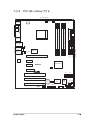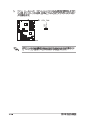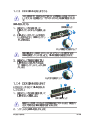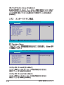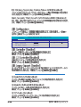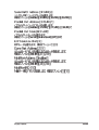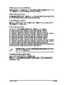
1
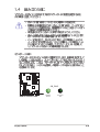
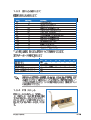
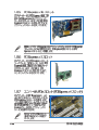
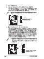
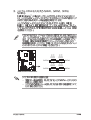
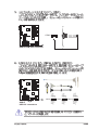
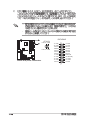
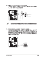
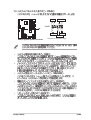
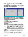
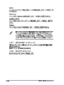
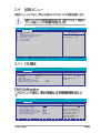
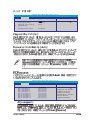
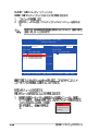
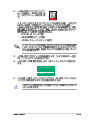
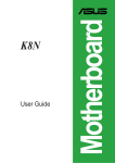
Motherboard
A8N-E
Checklist
Copyright© 2005 ASUSTeK COMPUTER INC. All Rights Reserved.
ii
iii
Features
Safeguards
iv
v
®
®
vi
Federal Communications Commission Statement
This device complies with Part 15 of the FCC Rules. Operation is subject to
the following two conditions:
• This device may not cause harmful interference, and
• This device must accept any interference received including interference
that may cause undesired operation.
This equipment has been tested and found to comply with the limits for a
Class B digital device, pursuant to Part 15 of the FCC Rules. These limits are
designed to provide reasonable protection against harmful interference in a
residential installation. This equipment generates, uses and can radiate radio
frequency energy and, if not installed and used in accordance with
manufacturer’s instructions, may cause harmful interference to radio
communications. However, there is no guarantee that interference will not
occur in a particular installation. If this equipment does cause harmful
interference to radio or television reception, which can be determined by
turning the equipment off and on, the user is encouraged to try to correct
the interference by one or more of the following measures:
• Reorient or relocate the receiving antenna.
• Increase the separation between the equipment and receiver.
• Connect the equipment to an outlet on a circuit different from that to
which the receiver is connected.
• Consult the dealer or an experienced radio/TV technician for help.
The use of shielded cables for connection of the monitor to the graphics
card is required to assure compliance with FCC regulations. Changes or
modifications to this unit not expressly approved by the party
responsible for compliance could void the user’s authority to operate
this equipment.
Canadian Department of Communications Statement
This digital apparatus does not exceed the Class B limits for radio noise
emissions from digital apparatus set out in the Radio Interference
Regulations of the Canadian Department of Communications.
This class B digital apparatus complies with Canadian ICES003.
vii
viii
ix
x
®
™
®
™
™
\
®
™
®
™
™
®
®
®
™
1
1-1
®
1-2
™
®
™
™
™
®
®
®
®
™
™
" "
®
" "
1-3
®
®
1-4
®
™
™
®
®
1-5
1-6
SB_PWR
A8N-E
®
A8N-E Onboard LED
ON
Standby
Power
OFF
Powered
Off
1-7
A8N-E
1-8
24.5cm (9.6in)
PS/2KBMS
T: Mouse
B: Keyboard
CHA2_FAN CPU_FAN
ATX12V
AUX
FLOPPY
PWR_FAN
SEC_IDE
FP_AUDIO
PCIEX16_1
PCIEX1_1
PCIEX1_2
nForce4 ultra
A8N-E
CHIP_FAN
PCIEX4_1
®
PCI1
SATA4
SATA3
SATA2
SATA1
PCI2
CR2032 3V
Lithium Cell
CMOS Power
CLRTC
Super
I/O
4Mb
BIOS
ACL850
EATXPWR
Marvell
88E1111
Top:Line In
Center:Line Out
Bottom:Mic In
30.5cm (12.0in)
CD
PRI_IDE
Top:Rear Speaker Out
Center:
Side Speaker Out
Below:
Center/Subwoofer
DDR DIMM_B2 (64 bit,184-pin module)
LAN1_USB34
DDR DIMM_B1 (64 bit,184-pin module)
USB12
DDR DIMM_A2 (64 bit,184-pin module)
DDR DIMM_A1 (64 bit,184-pin module)
Socket 939
SPDIF_O2
PARALLEL PORT
SPDIF_O
PCI3
USB78
SB_PWR
USB56
USB910
GAME
CHA1_FAN
CHASSIS
PANEL
COM1
1-9
™
A8N-E
®
A8N-E CPU Socket 939
1-10
™
™
1-11
™
1-12
™
1-13
GND
+12V
Rotation
CPU_FAN
A8N-E
®
A8N-E CPU fan connector
1-14
DIMM_B2
DIMM_B1
DIMM_A2
DIMM_A1
A8N-E
®
A8N-E 184-pin DDR DIMM sockets
1-15
DIMM
A
256MB
512MB
256MB
512MB
256MB
512MB
256MB
512MB
1024MB
256MB
512MB
256MB
256MB
512MB
512MB
256MB
512MB
256MB
512MB
256MB
512MB
1024MB
256MB
512MB
1-16
KINGSTON
KINGSTON
KINGSTON
KINGSTON
KINGSTON
KINGSTON
KINGSTON
KINGSTON
KINGSTON
SAMSUNG
SAMSUNG
SAMSUNG
SAMSUNG
SAMSUNG
SAMSUNG
MICRON
MICRON
Infineon
Infineon
CORSAIR
CORSAIR
CORSAIR
Hynix
Hynix
KVR400X64C3A/256
KVR400X64C3A/512
KVR400X72C3A/256
KVR400X72C3A/512
KVR400X64C3A/256
KVR400X64C3A/512
KVR400X64C3A/256
KVR400X64C3A/512
HYB25D512800BE-5B
M381L3223ETM-CCC
M381L6423ETM-CCC
M368L3223ETM-CCC
M368L3223FTN-CCC
M368L6423FTN-CCC
M368L6523BTM-CCC
MT8VDDT3264AG-40BCB
MT16VDDT6464AG-40BCB
HYS64D32300HU-5-C
HYS64D64320HU-5-C
CMX256A-3200C2PT
VS512MB400
TWINX2048-3200C2
HYMD232645D8J-D43
HYMD264646D8J-D43
Hynix
Hynix
Mosel
Mosel
Infineon
Infineon
KINGSTON
KINGSTON
N/A
SAMSUNG
SAMSUNG
SAMSUNG
SAMSUNG
SAMSUNG
SAMSUNG
MICRON
MICRON
Infineon
Infineon
Winbond
VALUE seLecT
N/A
Hynix
Hynix
SS
DS
SS
DS
SS
DS
SS
DS
DS
SS
DS
SS
SS
DS
SS
SS
DS
SS
DS
SS
DS
DS
SS
DS
HY5DU56822BT-D43
HY5DU56822BT-D43
V58C2256804SAT5(ECC)
V58C2256804SAT5(ECC)
HYB25D256800BT-5B
HYB25D256809BT-5B
D3208DL2T-5
D328DIB-50
KVR400X64C3A/1G
K4H560838E-TCCC(ECC)
K4H560838E-TCCC(ECC)
K4H560838E-TCCC
K4H560838F-TCCC
K4H560838F-TCCC
K4H510838B-TCCC
MT46V32M8TG-5BC
MT46V32M8TG-5BC
HYB25D256800CE-5C
HYB25D256800CE-5C
W942508BH-5
VS32M8-5
N/A
HY5DU56822DT-D43
HY5DU56822DT-D43
•
•
•
•
•
•
•
•
•
•
•
•
•
•
•
•
•
•
•
•
•
•
•
B
C
•
•
•
•
•
•
•
•
•
•
•
•
•
•
•
•
•
•
•
•
•
•
•
•
•
•
•
•
•
•
•
•
•
•
•
•
•
•
•
•
•
•
•
2
1
1
2
1
1
1-17
1-18
1-19
1-20
CLRTC
A8N-E
1 2
2 3
®
Normal
(Default)
Clear CMOS
A8N-E Clear RTC RAM
1-21
1
3
2
4
5
6
7
8
14
13
12
11
®
10
9
®
™
ACT/LINK SPEED
LED
LED
LAN port
1-22
1-23
FLOPPY
NOTE: Orient the red markings on
the floppy ribbon cable to PIN 1.
A8N-E
®
PIN 1
®
PRI_IDE
A8N-E
SEC_IDE
A8N-E Floppy disk drive connector
PIN 1
A8N-E IDE connectors
1-24
NOTE: Orient the red markings
(usually zigzag) on the IDE
ribbon cable to PIN 1.
A8N-E
®
SATA2
GND
RSATA_RXP1
RSATA_RXN1
GND
RSATA_TXN1
RSATA_TXP1
GND
GND
RSATA_RXP2
RSATA_RXN2
GND
RSATA_TXN2
RSATA_TXP2
GND
GND
RSATA_RXP3
RSATA_RXN3
GND
RSATA_TXN3
RSATA_TXP3
GND
GND
RSATA_RXP4
RSATA_RXN4
GND
RSATA_TXN4
RSATA_TXP4
GND
®
™
SATA4
SATA3
SATA1
A8N-E SATA connectors
1-25
GND
+12V
Rotation
CPU_FAN
PWR_FAN
CHIP_FAN
A8N-E
CPU_FAN
GND
+12V
Rotation
CHA2_FAN
CHA2_FAN
PWR_FAN
GND
+12V
Rotation
®
A8N-E Fan connectors
1-26
CHIP_FAN
GND
+12V
Rotation
CHA1_FAN
CHA1_FAN
GND
+12V
Rotation
1
A8N-E
USB 2.0 connectors
USB56
1
1
USB+5V
USB_P9USB_P9+
GND
USB78
USB+5V
USB_P5USB_P5+
GND
®
USB+5V
USB_P10USB_P10 +
GND
NC
USB+5V
USB_P6USB_P6+
GND
NC
USB+5V
USB_P8USB_P8+
GND
NC
A8N-E
USB+5V
USB_P7USB_P7+
GND
COM1
PIN 1
®
A8N-E COM port connector
A8N-E
USB910
1-27
ATX12V
+12V DC GND
+12V DC GND
A8N-E
®
A8N-E ATX power connectors
1-28
EATXPWR
+3 Volts
-12 Volts
Ground
PSON#
Ground
Ground
Ground
-5 Volts
+5 Volts
+5 Volts
+5 Volts
Ground
+3 Volts
+3 Volts
Ground
+5 Volts
Ground
+5 Volts
Ground
Power OK
+5V Standby
+12 Volts
+12 Volts
+3 Volts
Left Audio Channel
Ground
Ground
Right Audio Channel
CD
(black)
A8N-E
®
AUX
(white)
Right Audio Channel
Ground
Ground
Left Audio Channel
+5V
J2B1
J2CX
MIDI_OUT
J2CY
J2B2
MIDI_IN
A8N-E Internal audio connectors
A8N-E
®
A8N-E Game connector
+5V
J1B1
J1CX
GND
GND
J1CY
J1B2
+5V
GAME
1-29
Chassis Signal
GND
+5VSB_MB
A8N-E
®
CHASSIS
(Default)
A8N-E Chassis intrusion connector
FP_AUDIO
BLINE_OUT_L
A8N-E
®
BLINE_OUT_R
+5VA
AGND
A8N-E Front panel audio connector
1-30
Line out_L
NC
Line out_R
MICPWR
MIC2
SPEAKER
+5V
Ground
Ground
Speaker
PLED-
PLED+
PLED
®
IDE_LED
Reset
Ground
A8N-E
PWR
Ground
IDE_LED+
IDE_LED-
PANEL
RESET
PWRSW
* Requires an ATX power supply.
A8N-E System panel connector
1-31
1-32
2
2-1
®
format A:/S
®
®
®
®
®
2-2
D:\bootdisk\makeboot a:
AwardBIOS Flash Utility for ASUS V1.01
(C) Phoenix Technologies Ltd. All Rights Reserved
For NF-KC804-A8N-E-00
DATE: 11/18/2004
Flash Type - SST 49LF004A/B /3.3V
File Name to Program:
Message: Please input File Name!
2-3
AwardBIOS Flash Utility for ASUS V1.01
(C) Phoenix Technologies Ltd. All Rights Reserved
For NF-KC804-A8N-E-00
DATE: 11/18/2004
Flash Type - SST 49LF004A/B /3.3V
File Name to Program: 1001.bin
Message: Do You Want To Save Bios (Y/N)
AwardBIOS Flash Utility for ASUS V1.01
(C) Phoenix Technologies Ltd. All Rights Reserved
For NF-KC804-A8N-E-00
DATE: 11/18/2004
1234567890123456789012345678901
1234567890123456789012345678901
1234567890123456789012345678901
1234567890123456789012345678901
123
123
123
123
123
123
123
123
123
Warning: Don’t Turn Off Power Or Reset System!
AwardBIOS Flash Utility for ASUS V1.01
(C) Phoenix Technologies Ltd. All Rights Reserved
For NF-KC804-A8N-E-00
DATE: 11/18/2004
Flash Type - SST 49LF004A/B /3.3V
File Name to Program: 1001.bin
Flashing Complete
Press <F1> to Continue
123
123
123
123 Write OK
F1 Reset
2-4
123
123
123
123 No Update
123
123
123
123 Write Fail
AwardBIOS Flash Utility for ASUS V1.01
(C) Phoenix Technologies Ltd. All Rights Reserved
For NF-KC804-A8N-E-00
DATE: 11/18/2004
Flash Type - SST 49LF004A/B /3.3V
File Name to Program: 1001.bin
Save current BIOS as:
Message:
AwardBIOS Flash Utility for ASUS V1.01
(C) Phoenix Technologies Ltd. All Rights Reserved
For NF-KC804-A8N-E-00
DATE: 11/18/2004
Flash Type - SST 49LF004A/B /3.3V
File Name to Program: 1001.bin
Checksum: DAD6H
Save current BIOS as: old.bin
Message: Please Wait!
AwardBIOS Flash Utility for ASUS V1.01
(C) Phoenix Technologies Ltd. All Rights Reserved
For NF-KC804-A8N-E-00
DATE: 11/18/2004
Flash Type - SST 49LF004A/B /3.3V
File Name to Program: 1001.bin
Now Backup System BIOS to
File!
1234567890123456789012345678901
1234567890123456789012345678901
1234567890123456789012345678901
Message: Please Wait!
2-5
Award BootBlock BIOS v1.0
Copyright (c) 2000, Award Software, Inc.
BIOS ROM checksum error
Detecting IDE ATAPI device...
Award BootBlock BIOS v1.0
Copyright (c) 2000, Award Software, Inc.
BIOS ROM checksum error
Detecting IDE ATAPI device...
Found CDROM, try to Boot from it... Pass
2-6
Award BootBlock BIOS v1.0
Copyright (c) 2000, Award Software, Inc.
BIOS ROM checksum error
Detecting IDE ATAPI device...
Award BootBlock BIOS v1.0
Copyright (c) 2000, Award Software, Inc.
BIOS ROM checksum error
Detecting IDE ATAPI device...
Found CDROM, try to Boot from it... Fail
Detecting floppy drive A media...
2-7
Insert Disk then press Enter or ESC to continue POST
AwardBIOS Flash Utility for ASUS V1.01
(C) Phoenix Technologies Ltd. All Rights Reserved
For NF-KC804-A8N-E-00
DATE: 11/18/2004
Flash Type - SST 49LF004A/B /3.3V
File Name to Program:
Message: Please wait...
2-8
®
®
2-9
®
2-10
®
2-11
2-12
Main
Advanced
Phoenix-Award BIOS CMOS Setup Utility
Power
Boot
Exit
System Time
System Date
Language
15 : 30 : 36
Wed, Nov 5 2004
[English]
Legacy Diskette A:
[1.44M, 3.5 in.]
Primary IDE Master
Primary IDE Slave
Secondary IDE Master
Secondary IDE Slave
First SATA Master
Second SATA Slave
Third SATA Master
Fourth SATA Slave
HDD SMART Monitoring
[ST321122A]
[ASUS CDS520/A]
[None]
[None]
[None]
[None]
[None]
[None]
[Disabled]
Installed Memory
256MB
F1:Help
ESC: Exit
↑↓ : Select Item
-/+: Change Value
→←: Select Menu Enter: Select Sub-menu
→←
Select Menu
Item Specific Help
Change the day, month,
year and century.
F5: Setup Defaults
F10: Save and Exit
2-13
2-14
Main
Advanced
Phoenix-Award BIOS CMOS Setup Utility
Power
Boot
Exit
System Time
System Date
Language
15 : 30 : 36
Wed, Nov 5 2004
[English]
Legacy Diskette A:
[1.44M, 3.5 in.]
Legacy Diskette A:
Primary IDE Master
[ST321122A]
..... [ ]
Primary IDE Slave Disabled [ASUS CDS520/A]
360K , 5.25
in.
..... [ ]
Secondary IDE Master
[None]
in.
..... [ ]
Secondary IDE Slave 1.2M , 5.25
[None]
in.
..... [ ]
First SATA Master 720K , 3.5[None]
in.
..... [ ]
Second SATA Slave 1.44M, 3.5[None]
in.
..... [ ]
Third SATA Master 2.88M, 3.5[None]
Fourth SATA Slave
[None]
HDD SMART Monitoring
[Disabled]
↑↓ :Move ENTER:Accept ESC:Abort
Installed Memory
256MB
F1:Help
ESC: Exit
↑↓ : Select Item
-/+: Change Value
→←
→←: Select Menu Enter: Select Sub-menu
Select Menu
Item Specific Help
Specifies the capacity
and physical size of
diskette drive A.
F5: Setup Defaults
F10: Save and Exit
2-15
Main
Advanced
Phoenix-Award BIOS CMOS Setup Utility
Power
Boot
Exit
System Time
System Date
Language
15 : 30 : 36
Wed, Nov 5 2004
[English]
Legacy Diskette A:
[1.44M, 3.5 in.]
Primary IDE Master
Primary IDE Slave
Secondary IDE Master
Secondary IDE Slave
First SATA Master
Second SATA Slave
Third SATA Master
Fourth SATA Slave
HDD SMART Monitoring
[ST321122A]
[ASUS CDS520/A]
[None]
[None]
[None]
[None]
[None]
[None]
[Disabled]
Installed Memory
256MB
F1:Help
ESC: Exit
↑↓ : Select Item
-/+: Change Value
→←: Select Menu Enter: Select Sub-menu
→←
[Français] [German] [English]
2-16
Select Menu
Item Specific Help
Change the day, month,
year and century.
F5: Setup Defaults
F10: Save and Exit
Phoenix-Award BIOS CMOS Setup Utility
Main
Primary IDE Master
Select Menu
PIO Mode
UDMA Mode
[Auto]
[Auto]
Primary IDE Master
Access Mode
UDMA Mode
[Auto]
[Auto]
[Auto]
Capacity
13579 MB
Cylinder
Head
Sector
Transfer Mode
26310
16
63
UDMA 4
F1:Help
ESC: Exit
↑↓ : Select Item
-/+: Change Value
→←: Select Menu Enter: Select Sub-menu
→←
Item Specific Help
Press [Enter] to
select
F5: Setup Defaults
F10: Save and Exit
2-17
2-18
Phoenix-Award BIOS CMOS Setup Utility
Main
Primary IDE Master
Select Menu
Extended Drive
Access Mode
[Auto]
[Auto]
Capacity
xxxxx MB
Cylinder
Head
Precomp
Landing Zone
Sector
xxxxx
xx
xx
xx
xx
F1:Help
ESC: Exit
↑↓ : Select Item
-/+: Change Value
→←: Select Menu Enter: Select Sub-menu
→←
Item Specific Help
Press [Enter] to
select
F5: Setup Defaults
F10: Save and Exit
2-19
2-20
Main
Advanced
Phoenix-Award BIOS CMOS Setup Utility
Power
Boot
Exit
CPU Configuration
PCIPnP
Onboard Device Configuration
JumperFree Configuration
LAN Cable Status
PEG Link Mode
Instant Music
F1:Help
ESC: Exit
Select Menu
Item Specific Help
Press Enter to Set
↑↓ : Select Item
-/+: Change Value
→←: Select Menu Enter: Select Sub-menu
→←
F5: Setup Defaults
F10: Save and Exit
Phoenix-Award BIOS CMOS Setup Utility
Advanced
CPU Configuration
CPU Type
AMD Athlon(tm) 64 FX-55 Processor
CPU Speed
3400MHz
Cache RAM
512K
DRAM Configuration
Hyper Transport Frequency
[Auto]
AMD K8 Cool’n’Quiet control
[Auto]
Select Menu
Item Specific Help
DRAM timing and
control
Phoenix-Award BIOS CMOS Setup Utility
Advanced
DRAM Configuration
Max Memclock (MHz)
1T/2T Memory Timing
CAS# latency (Tcl)
RAS# to CAS# delay (Trcd)
Min RAS# active time (Tras)
Row precharge Time (Trp)
Master ECC Enabled
[Auto]
[Auto]
[Auto]
[Auto]
[Auto]
[Auto]
[Disabled]
Select Menu
Item Specific Help
Place an artificial
memory clock limit on
the system. Memory is
prevented from
running faster than
this frequency.
2-21
’ ’
‘ ’
2-22
Phoenix-Award BIOS CMOS Setup Utility
Advanced
Frequency/Voltage control
x
Plug & Play O/S
Init Display First
[No]
[PCI Slot]
Resources Controlled By
IRQ Resources
[Auto]
PCI/VGA Palette Snoop
[Disabled]
Select Menu
Item Specific Help
Phoenix-Award BIOS CMOS Setup Utility
Advanced
IRQ Resources
IRQ-3 assigned to
IRQ-4 assigned to
IRQ-5 assigned to
IRQ-7 assigned to
IRQ-9 assigned to
IRQ-10 assigned to
IRQ-11 assigned to
IRQ-12 assigned to
IRQ-14 assigned to
IRQ-15 assigned to
[PCI
[PCI
[PCI
[PCI
[PCI
[PCI
[PCI
[PCI
[PCI
[PCI
Select Menu
Device]
Device]
Device]
Device]
Device]
Device]
Device]
Device]
Device]
Device]
Item Specific Help
Legacy ISA for devices
compliant with the
original PC AT bus
specification, PCI/ISA
PnP for devices
compliant with the
2-23
Phoenix-Award BIOS CMOS Setup Utility
Advanced
Onboard Device Configuration
IDE Function Setup
NVRAID Configuration
USB Configuration
Onboard NV LAN
Onboard LAN Boot ROM
AC97 Audio
Serial Port1 Address
Parallel Port Address
Parallel Port Mode
ECP MOde Use DMA
Game Port Address
Midi Port Address
x Midi Port IRQ
F1:Help
ESC: Exit
Select Menu
Item Specific Help
[Enabled]
[Disabled]
[Enabled]
[3F8/IRQ4]
[378/IRQ7]
[ECP+EPP]
[3]
[201]
[Disabled]
10
↑↓ : Select Item
-/+: Change Value
→←: Select Menu Enter: Select Sub-menu
→←
F5: Setup Defaults
F10: Save and Exit
Phoenix-Award BIOS CMOS Setup Utility
Advanced
Onboard Device Configuration
OnChip IDE Channel0
OnChip IDE Channel1
IDE DMA transfer access
Serial Port 1, 2
SATA DMA transfer
Serial Port 3, 4
SATA2 DMA transfer
IDE Prefetch Mode
2-24
[Enabled]
[Enabled]
[Enabled]
[Enabled]
[Enabled]
[Enabled]
[Enabled]
[Enabled]
Select Menu
Item Specific Help
Phoenix-Award BIOS CMOS Setup Utility
Advanced
NVRAID Configuration
x
x
x
x
x
x
x
x
RAID Enabled
IDE Primary Master RAID
IDE Primary Slave RAID
IDE Secondary Master RAID
IDE Secondary Slave RAID
First SATA Master RAID
Second SATA Master RAID
Third SATA Master RAID
Fourth SATA Master RAID
[Disabled]
Disabled
Disabled
Disabled
Disabled
Disabled
Disabled
Disabled
Disabled
Select Menu
Item Specific Help
2-25
Phoenix-Award BIOS CMOS Setup Utility
Advanced
USB Configuration
USB Controller
USB2.0 Controller
USB Legacy support
®
2-26
[Enabled]
[Enabled]
[Enabled]
Select Menu
Item Specific Help
2-27
Phoenix-Award BIOS CMOS Setup Utility
Advanced
JumperFree Configuration
x
x
x
x
x
x
x
2-28
Overclock Profile
Overclock Options
N.O.S. Option
CPU Frequency
PCI Express Clock
DDR Voltage
CPU Multiplier
CPU Voltage
[Auto]
Disable
Disable
200.00
100Mhz
Auto
Auto
Auto
Select Menu
Item Specific Help
2-29
Phoenix-Award BIOS CMOS Setup Utility
Advanced
JumperFree Configuration
POST Check LAN Cable
[Disabled]
Pair
1-2
3-6
4-5
7-8
Status
Open
Open
Open
Open
Select Menu
Item Specific Help
Length
N/A
N/A
N/A
N/A
Phoenix-Award BIOS CMOS Setup Utility
Advanced
JumperFree Configuration
PEG Link Mode
PEG Root Control
PEG Buffer Length
2-30
[Auto]
[Auto]
[Auto]
Select Menu
Item Specific Help
Phoenix-Award BIOS CMOS Setup Utility
Advanced
JumperFree Configuration
x
Instant Music
Instant Music CD-ROM Drive
[Disabled]
Primary Master
Select Menu
Item Specific Help
If enabled, power up
by PS/2 keyboard
function will be
disabled.
2-31
Main
Advanced
Phoenix-Award BIOS CMOS Setup Utility
Power
Boot
Exit
ACPI Suspend Type
ACPI APIC support
APM Configuration
Hardware Monitor
F1:Help
ESC: Exit
2-32
[S1&S3]
[Enabled]
↑↓ : Select Item
-/+: Change Value
→←: Select Menu Enter: Select Sub-menu
→←
Select Menu
Item Specific Help
Select the ACPI state
used for System
Suspend.
F5: Setup Defaults
F10: Save and Exit
Phoenix-Award BIOS CMOS Setup Utility
Power
APM Configuration
x
x
Restore on AC Power Loss
[Disabled]
PWR Button < 4 secs
[Instant Off]
Power On By PCI Devices
[Disabled]
Power On By External Modems [Disabled]
Power-On by RTC Alarm
[Disabled]
Date (of Month)
0
Resume Time (hh:mm:ss)
0 :0 : 0
Power Up By PS/2 Mouse
[Disabled]
Power Up By PS/2 Keyboard
[Disabled]
F1:Help
ESC: Exit
↑↓ : Select Item
-/+: Change Value
→←: Select Menu Enter: Select Sub-menu
→←
Select Menu
Item Specific Help
Press [ENTER] to
select whether or not
to restart the system
after AC power loss.
F5: Setup Defaults
F10: Save and Exit
2-33
2-34
Phoenix-Award BIOS CMOS Setup Utility
Power
Hardware Monitor
x
Q-Fan Controller
Vcore Voltage
3.3V Voltage
5V Voltage
12V Voltage
[Disabled]
1.50V
3.31V
4.94V
11.26V
CPU Temperature
M/B Temperature
CPU FAN Speed
CHA1 FAN Speed
CHIP FAN Speed
CPU Target Temperature
48ºC
38ºC
4962 RPM
0 RPM
5443 RPM
72ºC
F1:Help
ESC: Exit
↑↓ : Select Item
-/+: Change Value
→←: Select Menu Enter: Select Sub-menu
→←
Select Menu
Item Specific Help
Press [Enter] to
enable or disable
F5: Setup Defaults
F10: Save and Exit
2-35
Main
Advanced
Phoenix-Award BIOS CMOS Setup Utility
Power
Boot
Exit
Boot Device Priority
Removable Drives
Hard Disk Drives
CDROM Drives
Boot Settings Configuration
Security
F1:Help
ESC: Exit
Select Menu
Item Specific Help
↑↓ : Select Item
-/+: Change Value
→←: Select Menu Enter: Select Sub-menu
→←
F5: Setup Defaults
F10: Save and Exit
Phoenix-Award BIOS CMOS Setup Utility
Power
Boot Device Priority
1st
2nd
3rd
4th
2-36
Boot
Boot
Boot
Boot
Device
Device
Device
Device
[Removable]
[Hard Disk]
[CDROM]
[Disabled]
Select Menu
Item Specific Help
Select your boot
device priority
Phoenix-Award BIOS CMOS Setup Utility
Boot
Removable Drives
1. Floppy Disks
Select Menu
Item Specific Help
Phoenix-Award BIOS CMOS Setup Utility
Boot
Hard Disk Drives
1. 1st Master: XXXXXXXXX
2. Bootable Add-in Cards
Select Menu
Item Specific Help
Phoenix-Award BIOS CMOS Setup Utility
Boot
CDROM Drives
1. 1st Slave: XXXXXXXXX
Select Menu
Item Specific Help
2-37
Phoenix-Award BIOS CMOS Setup Utility
Boot
Boot Settings Configuration
x
x
Case Open Warning
Quick Boot
Boot Up Floppy Seek
Bootup Num-Lock
Typematic Rate Setting
Typematic Rate (Chars/Sec)
Typematic Delay (Msec)
OS Select For DRAM > 64MB
Full Screen LOGO
Halt On
F1:Help
ESC: Exit
2-38
[Enabled]
[Enabled]
[Enabled]
[On]
[Disabled]
6
250
[Non-OS2]
[Enabled]
[All Errors]
↑↓ : Select Item
-/+: Change Value
→←: Select Menu Enter: Select Sub-menu
→←
Select Menu
Item Specific Help
Press [Enter] to
enable or disable.
F5: Setup Defaults
F10: Save and Exit
™
Phoenix-Award BIOS CMOS Setup Utility
Boot
Boot Settings Configuration
Supervisor Password
User Password
Password Check
Clear
Clear
[Setup]
Select Menu
Item Specific Help
2-39
PASSWORD DISABLED !!!
Press any key to continue...
2-40
Main
Advanced
Phoenix-Award BIOS CMOS Setup Utility
Power
Boot
Exit
Exit & Save Changes
Exit & Discard Changes
Load Setup Default
Discard Changes
F1:Help
ESC: Exit
↑↓ : Select Item
-/+: Change Value
→←: Select Menu Enter: Select Sub-menu
→←
Select Menu
Item Specific Help
This option save data
to CMOS and exiting
the setup menu.
F5: Setup Defaults
F10: Save and Exit
2-41
2-42
3
ASUS A8N-E
3-1
®
®
3-2
®
®
®
™
®
®
’ ’
‘ ’
ASUS A8N-E
3-3
®
™
®
3-4
®
®
®
®
®
‘ ’
®
‘ ’
ASUS A8N-E
3-5
®
®
’
®
’
®
®
3-6
™
ASUS A8N-E
3-7
3-8
™
ASUS A8N-E
3-9
3-10
®
®
®
®
®
™
ASUS A8N-E
3-11
®
'
®
®
3-12
®
ASUS A8N-E
3-13
3-14
®
ASUS A8N-E
3-15
3-16
ASUS A8N-E
3-17
®
®
™
™
™
®
™
™
™
™
™
®
®
™
®
™
3-18
™
™
™
™
ASUS A8N-E
3-19
™
™
™
3-20
®
ASUS A8N-E
™
3-21
3-22
®
®
®
ASUS A8N-E
®
3-23
®
®
NVIDIA RAID Utility Oct 5 2004
- Define a New Array RAID Mode: Striping
Striping Block:
Free Disks
Loc
Disk Model Name
Array Disks
Loc
Disk Model Name
1.0.M
1.1.M
2.0.M
2.1.M
XXXXXXXXXXXXXXXXXX
XXXXXXXXXXXXXXXXXX
XXXXXXXXXXXXXXXXXX
XXXXXXXXXXXXXXXXXX
Optimal
[→] Add
[←] Del
[F6] Back
[F7] Finish
[TAB] Navigate
[↑↓] Select
[ENTER] Popup
®
Mirroring
Striping
Stripe Mirroring
Spanning
3-24
↑
8K
16K
32K
64K
128K
↓
Optim↓
Clear disk data?
[Y] YES
ASUS A8N-E
[N]
3-25
NVIDIA RAID Utility Oct 5 2004
- Array List Boot
Id
Status
Vendor
Array Model Name
No
4
Healthy
NVIDIA
MIRROR
[Ctrl-X]Exit
[↑
↑↓ ]Select
[B]Set Boot
XXX.XXG
[N]New Array
[ENTER]Detail
Array 1 : NVIDIA MIRROR XXX.XXG
- Array Detail RAID Mode: Mirroring
Striping Width: 1
Adapt
Channel
M/S
Index
Disk Model Name
Capacity
2
1
1
0
Master
Master
0
1
XXXXXXXXXXXXXXXXX
XXXXXXXXXXXXXXXXX
XXX.XXGB
XXX.XXGB
[R] Rebuild
3-26
Striping Block: 64K
[D] Delete
[C] Clear Disk
[ENTER] Return
Array 1 : NVIDIA MIRROR XXX.XXG
- Select Disk Inside Array RAID Mode: Mirroring
Striping Width: 1
Striping Block: 64K
Adapt
Channel
M/S
Index
Disk Model Name
Capacity
2
1
1
0
Master
Master
0
1
XXXXXXXXXXXXXXXXX
XXXXXXXXXXXXXXXXX
XXX.XXGB
XXX.XXGB
[↑↓] Select [F6] Back
[F7] Finish
Rebuild array?
[ENTER] OK
ASUS A8N-E
[ESC] Cancel
3-27
Array 1 : NVIDIA MIRROR XXX.XXG
- Array Detail RAID Mode: Mirroring
Striping Width: 1
Striping Block: 64K
Adapt
Channel
M/S
Index
Disk Model Name
Capacity
2
1
1
0
Master
Master
0
1
XXXXXXXXXXXXXXXXX
XXXXXXXXXXXXXXXXX
XXX.XXGB
XXX.XXGB
[R] Rebuild
[D] Delete
[C] Clear Disk
Delete this array?
[Y] YES
3-28
[N] No
[ENTER] Return
Array 1 : NVIDIA MIRROR XXX.XXG
- Array Detail RAID Mode: Mirroring
Striping Width: 1
Striping Block: 64K
Adapt
Channel
M/S
Index
Disk Model Name
Capacity
2
1
1
0
Master
Master
0
1
XXXXXXXXXXXXXXXXX
XXXXXXXXXXXXXXXXX
XXX.XXGB
XXX.XXGB
[R] Rebuild
[D] Delete
[C] Clear Disk
[ENTER] Return
Clear disk data?
[Y] YES
ASUS A8N-E
[N]
3-29
®
®
®
\
3-30
\
\
\
" "
’
®
®
ASUS A8N-E
3-31
' '
' '
' '
®
®
' '
3-32