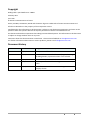
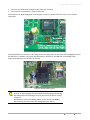
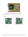
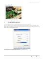
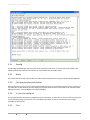
1
Amino Technical Note 005 Debug Cable – Quick Reference February 2011 i CONTENTS INDEX © Amino Communications Ltd. 2011 CONFIDENTIAL Copyright Debug Cable ‐ Quick Reference –TN005 February 2011 Issue 109 © Amino Communications Ltd. 2011 Amino, AmiNET, AssetHouse, Mood and the Amino logo are trademarks of Amino Communications Ltd. All other trademarks are the property of their respective owners. Confidentiality: the information in this document is subject to non‐disclosure agreements and must not be passed to other third parties without the express permission of Amino Communications Ltd. This document describes components that undergo continual development. The information in this document is subject to change without notice at any time. Comments about the documentation are welcome. Please submit feedback to [email protected]. For further information about Amino or Amino products, please e‐mail [email protected]. Document history Version Date issued Changes 109 11/02/11 Added picture of flexicable. 108 14/01/11 Additional information added for modifying and locating the debug header, in particular when a case is fitted. 107 23/12/10 A129 and H140 pictures added. 106 5/10/10 A130Hv2 picture amended as debug position incorrectly shown. 105 13/09/10 Mood information added. Document changed to new Company format. © Amino Communications Ltd. 2011 CONFIDENTIAL INDEX CONTENTS ii iii CONTENTS INDEX © Amino Communications Ltd. 2011 CONFIDENTIAL Debug Cable – Quick Reference This document decribes how to set up and use the Amino debug cable on the AmiNET and Mood set‐top boxes (STBs). The debug cable is essential when testing an STB to aid in the rapid diagnosis of faults and unexpected behaviour. It is applicable to the following versions of STB: AmiNET Mood A103 Mood 400‐002 A110 Mood 400‐020 A110H Mood 400‐022 A125 Mood 400‐030 A129 A130EU/US Mood 400‐032 A130H M540 A130EU/USv2 A130Hv2 A130 A140 H140 A500 A530EU/US A540 1 The Debug Cable 1.1 Aminet x3x and Mood400‐002/020/022 STBs The Amino debug cable (part number 500‐745) has a black connector, a light grey plastic breakout box and a DB9 serial connector. It is also supplied with a debug header ‐ a black connector with 4 pins. © Amino Communications Ltd. 2011 CONFIDENTIAL INDEX CONTENTS 1 DEBUG CABLE – QUICK REFERENCE 1.2 Aminet x4x and Mood400 030/032 STBs The Amino flexi‐cable assembly (part number 512‐857‐00‐00‐CABL‐BP) has a black header and a 4‐way flexible cable attached. The flexible cable will normally be white or light blue but may vary depending on the supplier. 2 AmiNET STBs 2.1 Connecting the debug header to Aminet x3x STBs Fitting a debug header to an AmiNET x3x STB is a fairly simple process. Before you start you will need: • A Philips head screwdriver. • A debug header. • (Optional) A soldering iron and some solder. Firstly remove the screws on the rear of the unit (and on the A500, disconnect the two cables) and then slide the PCB backwards out of the case. The debug header fits into 4 holes on the circuit board. On each version of STB the location of the header holes is different ‐ see Locating the debug header positions ‐ Aminet x3x STBs for the locations. On every STB except the A530 (see the note below), the silk screen will be as shown in Figure 1. The two features to note are: 2 CONTENTS INDEX © Amino Communications Ltd. 2011 CONFIDENTIAL DEBUG CABLE – QUICK REFERENCE • there are two white marks along one side of the silk screening • the end pin is surrounded by a square solder pad. These features are both highlighted in red in Figure 1 and are a useful indication of the correct header orientation. Figure 1: Example header location The debug header has two slots on one edge. These slots align with the two white marks highlighted on the pcb silkscreen. In addition, the square pad indicates the position for the red wire of the debug cable. Insert the header pins into the holes on the pcb. . Figure 2: Debug cable in place NOTE If the header and cable are placed the wrong way round the box will not boot up, no LEDs will light, and there will be no debug output. Removing the debug cable and inserting it correctly will return the box to normal operation. Remember to remove the debug cable from the set‐top box before disconnecting the other end of the debug cable from the PC. © Amino Communications Ltd. 2011 CONFIDENTIAL INDEX CONTENTS 3 DEBUG CABLE – QUICK REFERENCE It is not strictly necessary to solder the debug header in place if it is inconvenient for you to do so. However, the header pins are not a tight fit in the holes in the pcb so if you do not solder the header in place, you may have to apply a slight pressure on the header to ensure good electrical connectivity. 2.1.1 Modifying and routing the debug header Extending the header pins The debug header can be modified using ‘Molex’* headers (or equivalent). Attaching these headers as shown in Figure 3 gives longer pins for insertion, and the plastic frame can be used to provide some compression force to hold the header in place if it is not soldered. *Molex 0.1” 4 way header, square pin, part number: 22‐27‐2041. Available from http://uk.farnell.com/ Attaching a ribbon cable In some circumstances (for example, a test laboratory) you may need to use the debug facility with the STB case fitted. It is possible to solder a ribbon cable onto the pcb where the debug header would normally be fitted, and then route this cable outside the case. NOTE If you solder a ribbon cable between the debug header and the pcb, ensure you connect the cable ‘pin to pin’. For example, use the red wire between the header pin and the square solder pad which it would normally be fitted into, then connect the remaining cables in the correct order. Routing the ribbon cable (x3x STBs) To route the cable out of the STB and allow you to refit the cover, we suggest you feed the ribbon cable through one of the holes in the back plate that are used when the STB is mounted vertically. 4 CONTENTS INDEX © Amino Communications Ltd. 2011 CONFIDENTIAL DEBUG CABLE – QUICK REFERENCE 2.2 Locating the debug header positions ‐ Aminet x3x STBs The pictures below highlight where to find the debug connector on the different versions: AmiNET103 © Amino Communications Ltd. 2011 CONFIDENTIAL AmiNET110 INDEX CONTENTS 5 DEBUG CABLE – QUICK REFERENCE AmiNET110H AmiNET125 AmiNET130EU/US AmiNET130H AmiNET130EU/USv2 AmiNET130Hv2 6 CONTENTS INDEX © Amino Communications Ltd. 2011 CONFIDENTIAL DEBUG CABLE – QUICK REFERENCE AmiNET130M AmiNET500 AmiNET530EU/US (see note below) NOTE 2.3 On the A530EU/US it is easier to connect the debug cable to the ‘underside’ of the PCB. When the casing is removed this is the side of the PCB that is exposed but is not the side showing the silk screen. However, the end pin of the debug header position is still marked with a square solder pad. Connecting the debug cable to Aminet x4x STBs On the x4x series STBs you can use the standard flexi‐cable adaptor provided by Amino to extend the cable. This can be threaded through the back plate alongside the RJ45 connector so that the STB can be used with the case fitted but still with debug facilities available. © Amino Communications Ltd. 2011 CONFIDENTIAL INDEX CONTENTS 7 DEBUG CABLE – QUICK REFERENCE 8 CONTENTS INDEX © Amino Communications Ltd. 2011 CONFIDENTIAL DEBUG CABLE – QUICK REFERENCE 2.4 Locating the debug header positions ‐ Aminet x4x STBs AmiNET A140 and A129 AmiNET A540 AmiNET H140 3 Mood STBs 3.1 Connecting the debug cable to Mood STBs Fitting a debug cable to a Mood STB is a simple process. Before you start you will need: • A Philips head screwdriver or a T‐10 torx head screwdriver depending on the model • A debug header. Remove the cover retaining screws on the unit and slide the cover backwards and off the STB. The header position is in a different place on each of the 002, 020 and 022 STBs. The header type on the 030 and 032 STBs is the flexi‐cable type as on the AmiNET x4x series STBs . © Amino Communications Ltd. 2011 CONFIDENTIAL INDEX CONTENTS 9 DEBUG CABLE – QUICK REFERENCE 3.2 Locating the debug header positions ‐ Mood STBs The pictures below highlight where to find the debug connector on each version. NOTE The header fitted to the Mood STBs 002, 020, 022 is not polarised, so it is possible to fit the debug cable the wrong way round. For these versions, in each picture the arrow indicates the position of the red wire in the debug cable. Remember to remove the debug cable from the set‐top box before disconnecting the other end of the debug cable from the PC. Mood 400‐002 Mood 400‐020 Mood 400‐022 Mood 400‐030 10 CONTENTS INDEX © Amino Communications Ltd. 2011 CONFIDENTIAL DEBUG CABLE – QUICK REFERENCE Mood 400‐032 (Serial ATA cable removed for clarity) 4 Using the Debug Cable To use the Amino debug cable connect the DB9 plug to the serial port on your PC. Open your terminal software, for example, Minicom or Hyperterminal and connect at 115200 bps, 8 bits,1 stop bit, NO parity and NO flow control.Your terminal window should now show the debug output from your STB and allow you to log in to the console. The standard Amino username and password are root and root2root. © Amino Communications Ltd. 2011 CONFIDENTIAL INDEX CONTENTS 11 DEBUG CABLE – QUICK REFERENCE 5 Useful Commands This section details some useful commands that can be run using the debug cable in either IntActOS or Linux. IntActOS is a simple Operating System that is started when the STB is booted. It enables the programming of code images and launches Linux, the STBs main operating system. The debug cable can also be used to view the debug messages which appear on the console as part of the normal operation of the STB. For example, you will be able to immediately see the status of all stages of a software upgrade, see the status of the video engine when playing a clip, and track down problems with PID detection, among other things. 5.1 IntActOS To enter IntActOS 1. Connect the debug cable and power on the STB 2. At the “Hit ENTER to stop normal operation ...” prompt, press Enter to enter IntActOS. The prompt I> will appear as shown below. The following list of useful commands are not case sensitive. 5.1.1 Show All The show all command shows the values stored in the NOR flash. For example: I>show all Locked : 00 BoxID : 701306D000085 BoardRev : 2 VideoMode : 1 OutFormat : 2 12 CONTENTS INDEX © Amino Communications Ltd. 2011 CONFIDENTIAL DEBUG CABLE – QUICK REFERENCE RFChan : 167 RFMode : 0 RFFreqTbl : 0 CAID : F0F0F0F0 NDSSoftwareVersion : 00000000 NDSDriverVersion : 00 ManufacturerID : 1D STBModelType : 01 HardwareVersion : 01 MACaddress : 00:02:02:0C:91:E0 Ethernet : 0 UseDHCP : Y IPaddress : 0.0.0.0 Gateway : 0.0.0.0 Netmask : 0.0.0.0 TimeServer : 0.0.0.0 DNS : 0.0.0.0 McastAdr : 0.0.0.0 McastPort : 0 I> 5.1.2 Format The format command is used to completely erase the NAND flash and therefore any software loaded onto the box. This will put the box into a multicast aware state, ready to receive a new software image from a multicast (middleware) server. 5.1.3 Reset The reset command is used to exit from IntActOS. 5.1.4 Help Shows all the available commands. 5.2 Linux This section has a brief list of useful commands that will help you gather information about the STB. Most of these are standard Linux commands. Once the box has booted up fully into Linux, the console will show the message “Please press Enter to activate this console.” Pressing Enter prompts you for the username and password (root and root2root) © Amino Communications Ltd. 2011 CONFIDENTIAL INDEX CONTENTS 13 DEBUG CABLE – QUICK REFERENCE 5.2.1 Ifconfig The ifconfig command tells you the status of the interfaces on the box, it will tell you the IP address and subnet mask of the interface and statistics on transmitted and received packets. 5.2.2 Route This command shows the routing table. The most useful information here is generally the default gateway. 5.2.3 Cat /proc/sys/dev/eth0/lnkfail Running the command cat /proc/sys/dev/eth0/lnkfail will return a 1 if the Ethernet link is down, and 0 if it is up. Other files in this directory are also useful, for example aspeed returns the speed of the interface while afduplx will return 1 for full duplex and 0 for half duplex. 5.2.4 Vi /mnt/nv/config.txt This command opens the browser configuration file in the editor vi. Other files in /mnt/nv that you may wish to edit include settings and netconf. Vi is a standard Linux editor and more information on its usage is available on the Internet. 5.2.5 14 Free CONTENTS INDEX © Amino Communications Ltd. 2011 CONFIDENTIAL DEBUG CABLE – QUICK REFERENCE The free command returns the status of the memory in the box. 5.2.6 Reboot A user invoked reset of the set‐top box. 6 Quick Guide to Reflashing an STB It is possible to reflash a box by clearing the memory. This will put it into a multicast aware state, readyto receive a new software image from a multicast (middleware) server. The easiest way to do this is: 1. Connect the debug cable and power on the STB. 2. At the “Hit ENTER to stop normal operation ...” prompt press Enter to enter IntActOS. 3. The prompt I> will appear as shown above. 4. At the prompt type f (for format) and press Enter. 5. It will ask for confirmation – press Y. 6. Once the format is completed type reset and press Enter to reset the box. It will now boot up with the Loading… message on the screen and will attempt to load a new image from a multicast server. © Amino Communications Ltd. 2011 CONFIDENTIAL INDEX CONTENTS 15 DEBUG CABLE – QUICK REFERENCE 16 CONTENTS INDEX © Amino Communications Ltd. 2011 CONFIDENTIAL