1
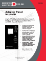
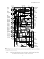
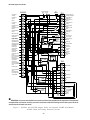
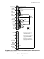
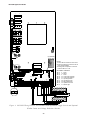
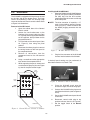
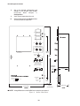
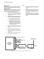
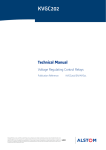
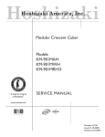
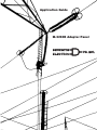
Application Guide M-2293B Adapter Panel CONTROLS Adapter Panel M-2293B Adapts M-2001 Series Digital Tapchanger Control to Replace Solid-State Controls for General Electric ML-32 and VR-1 Regulators, and SM-1, SM-2, and SM-2A Regulator Controls • Provides direct mechanical replacement of the old regulator control using the same two hinge pins • Provides built-in CT shorting protection when the M-2001 Series Digital Tapchanger Control is removed • Optional SCADA Cutout (Local/ Remote) switch (for use with SCADA enabled M-2001C controls) allows Local Blocking of SCADA commands • Optional SCAMPTM (SCADA Controlable Auto/Maual Pushbutton) switch replaces AUTO/OFF/MANUAL toggle switch • Optional 2 Level Local Voltage Reduction switch Industry Leader Since 1969 Made in the USA M-2293B Adapter Panel The M-2293B is an adapter panel which, when combined with the M-2001 Series Digital Tapchanger Control, provides convenient direct replacement of solid-state controls for General Electric ML-32 and VR-1 regulators, and SM-1, SM-2 and SM-2A regulator controls. The M-2293B consists of a front panel with hinge leaves, and mounts into the control cabinet using the same two hinge pins which must be saved from the original control. Interface External connections are made using a wiring harness that connects from a sixteen-position terminal block to the "NN" terminal block on the existing control cabinet. An additional terminal block provides auxiliary functions, including self-test alarm, user-programmable alarm, auto disable and manual raise/lower. Features Separate fuses for test terminal, voltage sensing and motor power are on the front panel, and spare fuses for each are located in the fuse holder. Binding posts on the front panel allow easy connections for test procedures. RAISE/OFF/LOWER, AUTO/OFF/MANUAL and VOLTAGE SOURCE switches, DRAG HANDS RESET pushbutton, and NEUTRAL LIGHT are standard. AUTO/OFF/MANUAL switch may be configured for switch status detection. NEUTRAL LIGHT will light to indicate that the regulator is in the neutral position, for those regulators equipped with a circuit for this purpose. The M-2293B includes the capability to change out the control and adapter panel as one component. The M-2293B wiring harness includes two plug connectors. One connector disconnects the control input wiring and the other includes built-in CT shorting to isolate the line current CT. Options SCADA CUTOUT switch allows Local blocking of SCADA commands (for use with SCADA enabled M-2001C controls). The SCADA Cutout switch must be used with a M-2001 Series Control with firmware version D-0146V08.01.22 or later installed. SCAMPTM (SCADA Controlable Auto/Manual Pushbutton) switch allows the Auto/Manual state on the adapter panel to be changed by a SCADA command. The SCAMP pushbutton switch must be used with a M2001 Series Control with firmware version D-0146V08.05.XX or later installed. Voltage Reduction switch allows 2 levels of Voltage Reduction to be selected. Testing Specifications High Voltage: All input and output terminals will withstand 1500 V ac rms to chassis or instrument ground for one minute with a leakage current not to exceed 25 mA, for all terminals to ground. Input and output circuits are electrically isolated from each other, from other circuits and from ground. Surge Withstand Capability: All input and output circuits are protected against system transients. Units pass all requirements of ANSI/IEEE C.37.90.1-1989 defining surge withstand capability. Radiated Electromagnetic Withstand Capability: All units are protected against electromagnetic radiated interference from portable communications transceivers. –2– M-2293B Adapter Panel Environmental Temperature Range: Functionality is maintained from –40° to +85° C. Humidity: Functionality is maintained under 95% relative humidity (non-condensing). Fungus Resistance: A conformal printed circuit board coating inhibits fungal growth. Physical Size with M-2001 Series Digital Tapchanger Control: 15.00" high x 9.25" wide x 4.185" deep (38.1 cm x 23.5 cm x 10.5 cm) Approximate Weight: 2 lbs, 7 oz (1.11 kg) Approximate Shipping Weight: 5 lbs, 7 oz (2.47 kg) Approximate Weight with M-2001 Series Digital Tapchanger Control: 6 lbs, 2 oz (2.78 kg) Approximate Shipping Weight with M-2001 Series Digital Tapchanger Control: 11 lbs, 2 oz (5.05 kg) Warranty The M-2293B Adapter Panel is covered by a five year warranty from date of shipment. Specification is subject to change without notice. –3– © 2004 Beckwith Electric Co. All Rights Reserved. Printed in USA 800-2293B-SP-03MC2A) 01/13 WARNING DANGEROUS VOLTAGES, capable of causing death or serious injury, are present on the external terminals and inside the equipment. Use extreme caution and follow all safety rules when handling, testing or adjusting the equipment. However, these internal voltage levels are no greater than the voltages applied to the external terminals. DANGER! HIGH VOLTAGE – This sign warns that the area is connected to a dangerous high voltage, and you must never touch it. PERSONNEL SAFETY PRECAUTIONS The following general rules and other specific warnings throughout the manual must be followed during application, test or repair of this equipment. Failure to do so will violate standards for safety in the design, manufacture, and intended use of the product. Qualified personnel should be the only ones who operate and maintain this equipment. Beckwith Electric Co., Inc. assumes no liability for the customer’s failure to comply with these requirements. – This sign means that you should refer to the corresponding section of the operation manual for important information before proceeding. Always Ground the Equipment To avoid possible shock hazard, the chassis must be connected to an electrical ground. When servicing equipment in a test area, the Protective Earth Terminal must be attached to a separate ground securely by use of a tool, since it is not grounded by external connectors. Do NOT operate in an explosive environment Do not operate this equipment in the presence of flammable or explosive gases or fumes. To do so would risk a possible fire or explosion. Keep away from live circuits Operating personnel must not remove the cover or expose the printed circuit board while power is applied. In no case may components be replaced with power applied. In some instances, dangerous voltages may exist even when power is disconnected. To avoid electrical shock, always disconnect power and discharge circuits before working on the unit. Exercise care during installation, operation, & maintenance procedures The equipment described in this manual contains voltages high enough to cause serious injury or death. Only qualified personnel should install, operate, test, and maintain this equipment. Be sure that all personnel safety procedures are carefully followed. Exercise due care when operating or servicing alone. Do not modify equipment Do not perform any unauthorized modifications on this instrument. Return of the unit to a Beckwith Electric repair facility is preferred. If authorized modifications are to be attempted, be sure to follow replacement procedures carefully to assure that safety features are maintained. PRODUCT CAUTIONS Before attempting any test, calibration, or maintenance procedure, personnel must be completely familiar with the particular circuitry of this unit, and have an adequate understanding of field effect devices. If a component is found to be defective, always follow replacement procedures carefully to that assure safety features are maintained. Always replace components with those of equal or better quality as shown in the Parts List of the Instruction Book. Avoid static charge This unit contains MOS circuitry, which can be damaged by improper test or rework procedures. Care should be taken to avoid static charge on work surfaces and service personnel. Use caution when measuring resistances Any attempt to measure resistances between points on the printed circuit board, unless otherwise noted in the Instruction Book, is likely to cause damage to the unit. TABLE OF CONTENTS M-2293B Adapter Panel Application Guide 1.0 Introduction .................................................................................................................. 1 1.1 Description ................................................................................................................... 1 Standard Features ....................................................................................................... 1 Control Switches .......................................................................................................... 1 Binding Posts ............................................................................................................... 1 Status Indicators .......................................................................................................... 1 Optional Control Switches ........................................................................................... 2 2.0 Application ................................................................................................................... 2 Typical Connections .................................................................................................... 2 External Connections ................................................................................................... 2 Lightning Protection ..................................................................................................... 2 Neutral Light Circuit ..................................................................................................... 2 Non-Sequential Operation (N/A for BASE-R Version) ................................................ 2 Figure 1 M-2001C and M-2293B Adapter Panel with Standard Auto/Off/Manual Toggle Switch and Optional Voltage Reduction and SCADA Cutout Switches ........ 3 Figure 2 M-2001C and M-2293B Adapter Panel with Optional SCAMP Auto/Manual, SCADA Cutout and Voltage Reduction Switches ............................... 4 Figure 3 External Connections .................................................................................. 5 Figure 4 M-2293B Wiring Harness with Standard Auto/Off/Manual Toggle Switch and Optional SCADA Cutout and Voltage Reduction Switches ...... 6 Figure 5 M-2293B Wiring Harness with Optional SCAMPTM Auto/Manual Pushbutton Switch, SCADA Cutout and Voltage Reduction Switches ..................... 7 Automatic Disable Input .............................................................................................. 8 Operations Counter Input ............................................................................................ 8 Local/Remote Input ...................................................................................................... 8 Multi-Step Voltage Reduction ...................................................................................... 8 Table 1 M-2293B Multi-Step Voltage Reduction External Connections .................. 8 Paralleling (N/A for BASE-RS and BASE-R Controls) ............................................... 8 Disabling Auto/Off/Manual Toggle Switch Status Detection ..................................... 8 3.0 Installation .................................................................................................................... 9 Removal of the GE Control ......................................................................................... 9 Figure 6 General Electric Control in Cabinet ........................................................... 9 Installing the M-2293B/M-2001 .................................................................................... 9 Figure 7 M-2001 Harness Connector ........................................................................ 9 Figure 8 M-2001 V-Notch Orientation ....................................................................... 9 Figure 9 Outline Dimensions ................................................................................... 10 4.0 Bench Test (M-2001 Connected to M-2293B) .......................................................... 11 Test Equipment .......................................................................................................... 11 Setup .......................................................................................................................... 11 Table 2 Initial Settings ............................................................................................ 11 Procedure ................................................................................................................... 11 Resistance ................................................................................................................. 11 Reactance .................................................................................................................. 12 Paralleling (N/A For BASE-R Version) ...................................................................... 12 Voltage Source Switch .............................................................................................. 12 Drag Hands Reset ..................................................................................................... 12 Counter/Neutral Light/Tap Position ........................................................................... 12 Block Raise/Block Lower/Dead Band ....................................................................... 12 Figure 10 M-2293B Test Procedure External Connections (Comprehensive or BASE-T Version) ....................................................................... 13 Figure 11 M-2293B Test Procedure External Connections (BASE-R Version) .... 14 Basic Operational Test .............................................................................................. 15 In-Service Test .......................................................................................................... 15 5.0 Checkout Procedure .................................................................................................. 15 Pre-Test Conditions ................................................................................................... 15 Power.......................................................................................................................... 15 Load Current CT ........................................................................................................ 16 Figure 12 M-2293B Setup for Current Checkout Procedure .................................. 16 LDC ............................................................................................................................ 16 ©2004 Beckwith Electric Co. Printed in U.S.A. 800-2293B-AG-03MC4 04/15 M-2293B Application Guide 1.0 Application, Disabling Auto/Off/Manual Switch Status Detection, for the steps necessary to disable the AUTO/OFF/MANUAL switch detection function for M-2001 series units with an earlier firmware version. Introduction The Beckwith Electric M-2293B Adapter Panel, used in conjunction with the M-2001 Series Tapchanger Control, uses modern digital design and digital processing circuitry to achieve enhanced application flexibility plus an overall stability and resolution unattainable with electromechanical and analog design tapchanger controls. CMOS semiconductors are used throughout the design. Control Switches RAISE/LOWER/OFF switch allows local manual raise and lower commands to be initiated AUTO/OFF/MANUAL switch allows auto operation of the control or manual operation from the panel by using the Raise/Lower toggle switch. The AUTO/ OFF/MANUAL switch status may be read by a M-2001 series control with firmware version D-0067V07.08.15 or later installed. This application guide should be used in conjunction with the M-2001C Instruction Book for M-2001 Series applications information. 1.1 When the M-2001C Input Selection 1 screen in the Configuration menu is set to Switch Status Input, the seal-in input will operate as a switch status input. All seal-in input functions will be disabled. In this mode, the switch status on the adapter panel can be read to determine if it is in Auto or Manual. The status can be read through the seal-in/switch status data point in the communications protocols. Description Standard Features The M-2293B Adapter Panel with the M-2001 Series Tapchanger Control provides a solid-state voltage control relay designed to directly replace the General Electric ML-32 and VR-1 Regulators and SM-1, SM-2, and SM-2A regulator controls. The combination of tapchanger control and adapter panel includes the following features: • Voltage waveform sampling and digital processing circuitry to ensure accurate voltage sensing. • Control accuracy is &0.3 % when tested in accordance with the ANSI/IEEE C57.15.9-1999 standard over a temperature range of –30° C to +65° C. The control accuracy is &0.5 % when tested over the full operational temperature range of –40° C to +85° C. • VOLTAGE SOURCE switch in the EXT position disconnects the voltage transformer input and connects the EXTERNAL POWER binding posts to the voltage input and motor circuit. The unit can be tested using an external 120 V RMS source of proper polarity applied to these terminals. Testing can be accomplished by adjusting the amplitude of the external source. DRAG HANDS RESET pushbutton resets the tapchanger position indicator drag hands. Binding Posts ▲ CAUTION: Do not reverse the ground and hot wires when connecting an external source. A 3 AG fuse (F2) is installed to protect the control from damage if these connections are accidentally reversed. Input and output circuits are protected against system transients. Units pass all requirements of ANSI/IEEE C37.90.11989, which defines surge withstand capability. All input and output terminals will withstand 1500 V ac RMS to chassis or instrument ground for one minute with a leakage current not to exceed 25 mA, for all terminals to ground. Input and output circuits are electrically isolated from each other, from other circuits and from ground. EXTERNAL POWER binding posts allow application of a 120 V RMS nominal voltage to the unit for test procedures. METER OUT binding posts allow reading of the input voltage when used in conjunction with the BIAS TEST VOLTAGE screen of the M-2001 Tapchanger Control. The M-2293B Adapter Panel factory configuration for AUTO/OFF/MANUAL switch status detection is Enabled. The M-2293B Adapter Panel AUTO/OFF/ MANUAL switch status detection feature is available to M-2001 series units that have Firmware Version D-0067V07.08.15 or later installed. See Section 2.0, Status Indicators NEUTRAL light illuminates when the regulator is in the neutral tap position. The Adapter Panel includes three replaceable fuses: Test Terminal (3 A), Voltage Sense (1 A), and Motor Power (6 A). –1– M-2293B Application Guide Optional Control Switches VOLTAGE REDUCTION (VR1/OFF/VR2) switch allows local voltage reduction 1 or 2 to be initiated. The M-0121 can be used with Beckwith Electric Tapchanger Controls when the only burden present is the Line Drop Compensator circuit of the voltage regulating relay. SCADA CUTOUT (LOCAL/REMOTE) switch allows the local blocking of SCADA commands. The SCADA Cutout switch must be used with a M-2001 Series Control with firmware version D-0146V08.01.22 or later installed. The M-0169A is used in high burden circuits, such as are found in paralleling schemes. Outputs of the auxiliary CTs are protected against overvoltage. For further information, obtain Beckwith Electric Application Note #17, “Basic Considerations for the Application of LTC Transformers and Associated Controls ” (available for download from www.beckwithelectric.com). SCAMP (AUTO/MANUAL) pushbutton allows the Auto/Manual state on the adapter panel to be changed by a SCADA command. The SCAMP pushbutton switch must be used with a M-2001 Series Control with firmware version D-0146V08.05.XX or later installed. The external connections for the M-2293B are made to terminal blocks TB1 and TB2 on the printed circuit board at the base of the adapter panel. The wiring harness and external connections for the M-2293B are shown in Figures 3, 4 and 5. Adapter Panel Wiring Harness Disconnects are provided in the M-2293B to provide the capability to change out the control and adapter panel as one unit. The wiring harness disconnects include a seperate line current CT disconnect that includes built-in CT shorting protection. 2.0 Lightning Protection ▲ CAUTION: For proper protection against system surges, chassis ground must be connected to earth ground. Application It has been determined that transient voltages in excess of 1500 V ac RMS can exist on the “ground” lead normally tied to TB1-8. In the tapchanger controls, these voltages are suppressed by varistors which still permit the unit to pass a 1500 V ac hi-pot test for one minute, with a leakage of approximately 15 mA, all terminals to ground. Typical Connections In general, the tapchanger motor must be operated from a different transformer than the VT used to measure regulated voltage. If this is not done, hunting at the upper band edge may result. As soon as the motor starts, and before it is sealed in, the motor current can drop the voltage within the band and reset the control. Some motor seal-in schemes are fast enough to prevent this, but others are not. Multiple VT grounds far apart must be avoided, since a varying difference in ground voltage could add or subtract from the effective voltage, and cause variation in the tapchanger control’s bandcenter voltage setpoint. Pulsed output can be used on the M-2001 (see Section 3.5, Pulsed Output). Typical connections for the M-2293B are shown on Figure 3. Connections are simplified and may not show all functions required in a typical load tapchanging transformer control scheme – for example, limit switches, etc. Neutral Light Circuit The M-2293B is prepared for use with regulators which use a neutral light. General Electric products typically require that the Neutral Light terminal TB1-11, be grounded inside the regulator when the light is to be illuminated. A switch on the printed circuit board is used to select the desired configuration (Up - Neutral, Down - Hot). External Connections Power and voltage sensing are obtained either from a common source or from independent sources having a nominal 120 V ac output. Normally, this is line-to-neutral voltage, although line-to-line voltage can also be used if recognition is made of any phase shift between the voltage and current signals when using line drop compensation. To configure the Neutral Light to be illuminated when TB1-11 is grounded inside the regulator, place the S1 toggle switch (located on the upper right hand corner of the adapter panel printed circuit board, see Figures 4 and 5) in the “Up” (Neutral) position. Load current must be reduced by an appropriate auxiliary current transformer to 0.2 A “full scale” before connecting to the M-2293B current inputs. The Beckwith Electric M-0121 (5.0 A to 0.2 A) or M-0169A (5.0 A or 8.66 A to 0.2 A) Auxiliary Current Transformer can be used for this purpose. Non-Sequential Operation (N/A for BASE-R Version) ▲ CAUTION: Voltage applied through dry contacts to actuate non-sequential input must be +12 V dc obtained from pin TB2-28. –2– M-2293B Application Guide M-2001 Test Terminal Fuse 3 A (Front Panel Inputs) Meter Voltage Out In TB1 Voltage Input (Polarity) 1 1 Non-Sequential / Auto Tapchange Inhibit Input Load Current (Return) 2 2 Voltage Reduction Step #2 Input Neutral 3 3 Circulating Current (Return) Load Current (Polarity) 4 4 Circulating Current (Polarity) Circulating Current (Polarity) 5 5 Tapchanger Raise Output Circulating Current (Return) 6 6 Tapchanger Lower Output Tapchanger Raise Output 7 7 Voltage Reduction Step #1 Input Motor Power Input 8 J4 J5 Voltage Reduction Step #2 Input 9 Contact "Wetting" Supply +12 V dc 10 INT OFF EXT 8 Neutral Motor Power Fuse (6 A) 9 Motor Power 120/ 240 V ac Supply Voltage In Fuse (1 A) 10 Regulated Voltage (120 V ac) 11 Neutral Light 12 Drag Hands Reset 13 Operations Counter Input 14 Line Current (Polarity) 15 Line Current (Return) 16 Motor Power Return INT Operation Counter Input #1/SW Status Operation Counter Input #2/SW Status 11 Up EXT (Netrual) 12 S1 Motor Seal-In Detector Input 13 Neutral Position Detector #1 14 Neutral Position Detector #2 15 Tapchanger Lower Output 16 Non-Sequential Operation/ Auto T.C. Inhibit Input/ SCADA Cutout Neutral Light OFF Drag Hands Reset Down (Hot) J12 R5 1 K Ohm Manual 17 Voltage Reduction Step #1 Input 18 Motor Seal-In Disconnect Output 19 User-Programmable Alarm 20 Self-Test Alarm 21 User-Programmable Alarm 22 OFF Manual Raise OFF (Momentary) Auto Manual TB2 OFF Manual Lower Auto 17 Local/Remote J14 18 19 Auto Disable J15 Non-Interruptable Power Supply Input 23 Self-Test Alarm 24 20 21 Manual Raise 22 Manual Lower 23 Motor Seal-In Input 24 Self-Test Alarm (Return) 25 Self-Test Alarm (Polarity) 26 User-Programmable Alarm (Return) 27 User-Programmable Alarm (Polarity) 28 +12 V dc Wetting Supply Optional Local SCADA Cutout Remote Optional VR1 Voltage Reduction OFF VR2 RT1 (.150 A) 8 WARNING: In no case should the line current circuit be interrupted with the regulator or transformer energized. Do not remove auxiliary current transformers without shorting the current inputs. Death or severe electrical shock can occur. Figure 1 M-2001C and M-2293B Adapter Panel with Standard Auto/Off/Manual Toggle Switch and Optional Voltage Reduction and SCADA Cutout Switches –3– M-2293B Application Guide Test Terminal Fuse 3 A (Front Panel Inputs) Meter Voltage Out In M-2001 TB1 Voltage Input (Polarity) 1 1 Non-Sequential / Auto Tapchange Inhibit Input Load Current (Return) 2 2 Voltage Reduction Step #2 Input Neutral 3 3 Circulating Current (Return) Load Current (Polarity) 4 4 Circulating Current (Polarity) Circulating Current (Polarity) 5 5 Tapchanger Raise Output Circulating Current (Return) 6 6 Tapchanger Lower Output Tapchanger Raise Output 7 7 Voltage Reduction Step #1 Input Motor Power Input 8 8 Neutral Voltage Reduction Step #2 Input 9 Motor Power Fuse (6 A) 9 Motor Power 120/ 240 V ac Supply Contact "Wetting" Supply +12 V dc 10 Voltage In Fuse (1 A) 10 Regulated Voltage (120 V ac) 11 Neutral Light 12 Drag Hands Reset 13 Operations Counter Input 14 Line Current (Polarity) 15 Line Current (Return) 16 Motor Power Return Operation Counter Input #1/SW Status J4 J5 OFF EXT INT 11 Neutral Light OFF Up EXT Operation Counter Input #2/SW Status 12 Motor Seal-In Detector Input 13 Neutral Position Detector #1 14 Neutral Position Detector #2 15 Tapchanger Lower Output 16 Non-Sequential Operation/ Auto T.C. Inhibit Input/ SCADA Cutout INT (Netrual) S1 Drag Hands Reset Down (Hot) J12 R5 1 K Ohm Optional SCAMP Auto/Manual 17 Voltage Reduction Step #1 Input 18 Motor Seal-In Disconnect Output 19 User-Programmable Alarm 20 Self-Test Alarm 21 User-Programmable Alarm 22 Manual Raise OFF (Momentary) TB2 Manual Lower 17 Local/Remote J14 18 19 Auto Disable J15 Non-Interruptable Power Supply Input 23 Self-Test Alarm 24 20 21 Manual Raise 22 Manual Lower 23 NC Optional Local SCADA Cutout Remote 24 25 Optional VR1 OFF Voltage Reduction 26 User-Programmable Alarm (Return) 27 User-Programmable Alarm (Polarity) 28 +12 V dc Wetting Supply VR2 RT1 (.150 A) 8 WARNING: In no case should the line current circuit be interrupted with the regulator or transformer energized. Do not remove auxiliary current transformers without shorting the current inputs. Death or severe electrical shock can occur. Figure 2 M-2001C and M-2293B Adapter Panel with Optional SCAMP Auto/Manual, SCADA Cutout and Voltage Reduction Switches –4– M-2293B Application Guide TB1 Non-Sequential / Auto Tapchange Inhibit Input 1 Non-Sequential / Auto Tapchange Inhibit Contact (Note #1) Voltage Reduction Step #2 Input 2 Voltage Reduction Step #2 Contact Circulating Current (Return) 3 Circulating Current (Polarity) 4 Tapchanger Raise Output 5 NN 27 Tapchanger Lower Output 6 NN 28 To Paralleling Unit (Note #2) Voltage Reduction Step #1 Input 7 Neutral 8 Motor Power 120/ 240 V ac Supply 9 Motor L R Voltage Reduction Step #1 Contact Neutral (Grd Stud) (Motor Return) NN 10 Regulated Voltage (120 V ac) 10 NN 9 20, 21 or 22 on T.C. Neutral Light 11 NN 31 Neutral Light Switch Drag Hands Reset 12 NN 29 Position Indicator Reset Operations Counter Input 13 NN 30 Line Current (Polarity) 14 NN 23 Line Current (Return) 15 NN 24 Motor Power Return 16 Voltage In (Reg 120 V) Operations Counter Switch Line Current CT CT Shorting Switch NN xx NN Terminals YY Harness/ Terminals TB2 17 Note #1: This feature is not available when a M-2001C (BASE-R) type control is used in conjunction with this adapter panel. Local/Remote 18 19 Note #2: These features are not available when either a M-2001C (BASE-R) or (BASE-RS) type control is used in conjunction with this adapter panel. Auto Disable 20 Manual Raise 21 Manual Lower 22 Motor Seal-In Input 23 Self-Test Alarm (Return) 24 Self-Test Alarm (Polarity) 25 User-Programmable Alarm (Return) 26 User-Programmable Alarm (Polarity) 27 +12 V dc Wetting Supply 28 Note #3: This feature is not available when either a M-2001C (BASE-R) control or SCAMP pushbutton switch is used in conjunction with this adapter panel. Note #3 Note #2 8 WARNING: Open CT secondary will result in high voltage at CT terminals. Death, severe injury or damage to equipment can occur. Do not operate with CT secondary open. Short circuit or apply burden at CT secondary during operation. Figure 3 External Connections –5– M-2293B Application Guide 1 2 F2 1 2 F3 1 2 F4 S3 Auto/Off/Manual Raise/Off/Lower 6 S2 6 1 1 2 5 4 2 5 3 4 3 Volt Red. Cutout S5 SCADA VR1/Off/VR2 Remote/Local S7 6 6 1 1 2 5 2 5 3 4 4 3 Voltage Source Int/Off/Ext 6 1 S4 5 2 3 4 B BP1 W Up (Neutral) Down (Hot) B NOTES: 1.Connect NN-10 to NN-26 for motor return. 2.Keep the existing ground wire from NN-10 to the chassis installed. 3.See Regulator nameplate for connection of NNJ to NN-20, 21 or 22. BP2 W J6 8 7 6 5 4 3 2 1 P1 S1 1 2 3 4 5 6 7 8 9 10 GE CABINET TERMINALS TB1-9 9 Power TB1-8 10 Return TB1-10 9 Power TB1-14 23 Load Current (Polarity) TB1-15 24 Load Current (Return) TB1-5 27 Tapchanger Raise TB1-6 28 Tapchanger Lower TB1-12 29 Drag Hands Reset TB1-13 30 Operations Counter TB1-11 31 Neutral Light 16 15 14 13 12 11 10 9 J7 24 23 22 21 20 19 18 17 11 10 9 8 7 6 5 4 3 1 4 5 6 7 8 9 2 3 2 1 J8 REV. BE# 450-00230 P-1970 S5 17 J15 J1 J14 TB2 1 2 3 4 5 6 7 8 9 10 11 12 TB1 13 14 15 16 D2 23 J14 8 9 10 20 21 22 23 24 8 9 10 20 21 22 23 24 J15 See NOTES 1 and 2 GND Stud 25 26 27 28 29 30 31 32 25 26 27 28 29 30 31 32 Figure 4 M-2293B Wiring Harness with Standard Auto/Off/Manual Toggle Switch and Optional SCADA Cutout and Voltage Reduction Switches –6– M-2293B Application Guide 1 2 F2 1 2 F3 1 2 F4 SCAMP S6 Auto/Manual Raise/Off/Lower 6 2 5 2 4 3 Volt Red. VR1/Off/VR2 SCADA S5 Remote/Local 6 6 1 2 5 S7 1 2 5 3 4 4 S2 1 1 3 Voltage Source Int/Off/Ext 6 1 S4 5 2 3 4 B BP1 W Up (Neutral) Down (Hot) B NOTES: 1.Connect NN-10 to NN-26 for motor return. 2.Keep the existing ground wire from NN-10 to the chassis installed. 3.See Regulator nameplate for connection of NNJ to NN-20, 21 or 22. BP2 W J6 P1 8 7 6 5 4 3 2 1 S1 1 2 3 4 5 6 7 8 9 10 GE CABINET TERMINALS TB1-9 9 Power TB1-8 10 Return TB1-10 9 Power TB1-14 23 Load Current (Polarity) TB1-15 24 Load Current (Return) TB1-5 27 Tapchanger Raise TB1-6 28 Tapchanger Lower TB1-12 29 Drag Hands Reset TB1-13 30 Operations Counter TB1-11 31 Neutral Light 16 15 14 13 12 11 10 9 J7 24 23 22 21 20 19 18 17 11 10 9 8 7 6 5 4 1 2 3 4 5 6 7 8 3 9 2 1 J8 REV. BE# 450-00230 P-1970 S5 TB2 J15 J1 J14 17 1 2 3 4 5 6 7 8 9 10 11 12 TB1 13 14 15 16 D2 23 J14 8 9 10 20 21 22 23 24 8 9 10 20 21 22 23 24 J15 See NOTES 1 and 2 GND Stud 25 26 27 28 29 30 31 32 25 26 27 28 29 30 31 32 Figure 5 M-2293B Wiring Harness with Optional SCAMPTM Auto/Manual Pushbutton Switch, SCADA Cutout and Voltage Reduction Switches –7– M-2293B Application Guide The operation of the control can be interrupted during tapchanger operation by applying the “wetting” voltage of terminal TB2-28 to TB1-1 (timer reset for nonsequential operation input) on the printed circuit board through an external contact. This causes the output to de-energize and re-initialize the time delay circuit when the reset signal is removed. This function can be used to cause the LTC transformer, if so equipped, to wait for the unit to time out between tapchanges. amounts are set within the M-2001 Series Tapchanger Control software. Voltage Reduction Setpoint: Mulitplier Range Apply "Wetting Voltage" from TB2-28 to Terminal # Voltage Reduction Setpoint #1: 0 to 10% TB1-7 Voltage Reduction Setpoint #2: 0 to 10% TB1-2 Voltage Reduction Setpoint #3: 0 to 10% TB1-7 and TB1-2 Table 1 M-2293B Multi-Step Voltage Reduction External Connections Automatic Disable Input To disable automatic operation of the M-2293B, remove Jumper #15 (See Figures 4 and 5, for location) on the printed circuit board. Paralleling (N/A for BASE-RS and BASE-R Controls) See M-2001 Instruction Book, Section 4.9, Parallel Operation. If SCADA is used to enable and disable this function, a contact rated at 6 A minimum can be connected between the terminals. Disabling Auto/Off/Manual Toggle Switch Status Detection The Auto/Off/Manual Toggle Switch status detection feature is available on M-2001 Series Digital Tapchanger Controls that have Firmware Version D-0067V07.08.15 or later installed. To disable the Auto/Off/Manual Toggle Switch status detection feature for earlier firmware versions, perform the following: Auto disable may also be accomplished by closing a contact between TB1-1 and TB2-28. Operations Counter Input ▲ CAUTION: Do not apply any voltage to this terminal. An operations count is registered by momentarily grounding TB1-13 through an external dry contact from the load tapchanger. The input is level-sensitive. Make sure that any “wetting” voltages are removed from the counter contacts before installing the M-2293B Adapter Panel/M-2001 Tapchanger Control. Local/Remote Input Removing Jumper #14 (See Figures 4 and 5, for location) prohibits M-2001 operation by disabling the automatic raise and lower outputs and also by disabling the M-2293B Adapter Panel’s manual RAISE/OFF/LOWER toggle switch. Removing this jumper does not disable the SCADA-supplied motor voltage input to the manual raise/manual lower contacts on the adapter panel. Multi-Step Voltage Reduction ▲ CAUTION: Voltage applied through dry contacts to actuate Voltage Reduction Steps 1, 2, and 3 must be +12 V dc obtained from pin TB2-28 of the M-2293B adapter panel. On the M-2293B, TB1-2 and TB1-7 on the printed circuit board are used together to provide up to three levels of voltage reduction. The external connections to achieve these steps are shown in Table 1 and Figure 3, External Connections. Voltage reduction –8– 1. Ensure that all power is removed from the M-2293B Adapter Panel and M-2001 control. 2. From the rear of the M-2293B Adapter Panel locate (Figure 4) and remove the wire connected to Terminal S3-4 on the rear of the AUTO/OFF/MANUAL toggle switch. 3. Connect the wire removed in Step 2 to Terminal S2-4 on the rear of the RAISE/ OFF/LOWER switch. 4. See M-2001 Instruction Book Section 6.1, External Connections, for information regarding M-2001 settings to disable this function. M-2293B Application Guide 3.0 Installing the M-2293B/M-2001 1. Mount the M-2001 to the M-2293B Adapter panel by using the hardware provided in the cloth bag. Use the lock washers supplied between the screws and the top of the front panel. Installation The M-2293B is equipped with hinge leaves located on the right side of the adapter panel. The hinge leaves are oriented to match the existing hinge leaves of the General Electric control cabinet. Refer to Figure 9 for dimensions. ■ NOTE: The blue connector is keyed by a “V” notch in the middle to prevent incorrect mating (Figure 7). Check location of the key before plugging connector into the M-2001. Removal of the GE Control 1. Open the cabinet door of the General Electric control. 2. Loosen the two thumbscrews at the interface of the control cable plug (Item #1, Figure 6) and the tap position indicator on the regulator, then pull down on the plug to disconnect it. 3. Turn the knob on the control panel (Item #2, Figure 6), then swing the panel outward. 4. Disconnect the three plugs that connect the wiring harness of the front panel to the component board. 5. Remove all connections from the component board to the NN terminal blocks. 6. Using a screwdriver or other appropriate tool, remove the component board. 7. While supporting the panel, remove and save the two hinges pins (Item #3, Figure 6), then lift the panel off the hinges. Figure 7 2. M-2001 Harness Connector Plug the blue connector of the M-2293B harness into the bottom of the M-2001. If desired, bench testing may be performed as described in Section 4.0, Bench Test. Control Cable Plug B Thumbscrews Control Panel C Figure 8 DÕ Control Panel Knob Hinge Pins G E N E R A L GE E L E C T R I C Cabinet Door Figure 6 General Electric Control in Cabinet –9– M-2001 V-Notch Orientation 3. Place the M-2293B panel onto the enclosure hinges, then insert hinge pins. 4. Connect the M-2293B wiring harness to the NN terminal blocks (refer to Figures 4 and 5). 5. Secure the M-2293B control panel thumb screw latch. 6. Reconnect control cable plug to tap position indicator (Item #1, on Figure 6). 7. Set the toggle switch to the Manual position. M-2293B Application Guide 8. Set up the desired configuration and settings on the M-2001. See M-2001 Instruction Book Chapter 4, Configuration. 9. Verify manual operation of the unit. 10. Set the toggle switch to the Auto position and verify automatic operation. FUSES TEST TERMINAL 3 AMP VOLTAGE SENSE 1 AMP M2001 MOTOR POWER 6 AMP AUTO RAISE OFF OFF MANUAL LOWER SCADA VOLTAGE REDUCTION REMOTE VR1 OFF VR2 LOCAL USE NULL MODEM CABLE INT VOLTAGE SOURCE 10-3/4 [27.3] 15 [38.] OFF EXT EXTERNAL POWER WHITE TERMINAL IS GROUND. CAUTION: DO NOT APPLY VOLTAGE TO METER OUT TERMINALS. Maximum Projection METER OUT 1 [2.54] M-2293B TAPCHANGER CONTROL BECKWITH EL EC T RIC CO. INC. 3 [7.6] DRAG HANDS RESET NEUTRAL LIGHT Ma d e in U.S .A . 1-5/8 [4.1] Inches [Centimeters] 9-1/4 [23.5] FRONT ■ NOTE: Voltage Reduction and SCADA Cutout switches are optional. Figure 9 Outline Dimensions –10– 3-1/8 [7.9] SIDE M-2293B Application Guide Bench Test (M-2001 Connected to M-2293B) FUNCTION INITIAL SETTING Bandcenter 120.0 V ■ NOTE: This test assumes that the M-2001 Tapchanger Control is connected to the M-2293B Adapter Panel. Bandwidth 2.0 V LDC Resistance 0.0 V LDC Reactance 0.0 V Paralleling N/A For BASE- R Version Circulating Current Method Block Raise 135.0 V Block Lower 105.0 V 4.0 Test Equipment • 0–200 MA current supply with phase angle settings of 0° to +90°. ▲ CAUTION: The current input to the M-2001 is rated at 0.2 A continuous, 0.4 A for two hours, and 4.0 A for 1 second. • 90–145 V ac voltage source at 60 Hz Deadband 2.0 V • High impedance true RMS voltmeter with accuracy on ac of at least &0.2% of reading Time Delay 5.0 Seconds • Accurate stop watch Setup 1. Table 2 Initial Settings Procedure ▲ CAUTION: Do not reverse the ground and hot wires when connecting an external source. Make electrical connections as follows: a. If testing an M-2001 Series Tapchanger Control other than a M-2001C BASE-R Version, then make electrical setup connections as described in Figure 10, M-2293B (Comprehensive or BASE-T Version) Test Procedure External Connections. b. If testing a BASE-R M-2001C then make electrical setup connections as described in Figure 11, M-2293B (BASE-R Version) Test Procedure External Connections. ■ NOTE: Refer to the M-2001 Instruction Book Appendix A, Figures A-1 through A-13, for the locations of screens within the software. ■ NOTE: There is a one-second delay between the out-of-band condition and panel LED indication. 1. Apply 120 V ac from the power source. 2. The display of the M-2001 will automatically advance to the Local Voltage screen. 3. Increase voltage to 121.2. The LOWER LED should illuminate. 4. Decrease voltage to 118.8. The RAISE LED should illuminate. 5. Set the input voltage to 120.0 V ac, then wait for the RAISE and LOWER LEDs to extinguish. 6. Increase voltage to 122.0 V ac, then start timing when the voltage passes 121.0 V ac. 7. Stop timing when the lamp connected to the Lower output illuminates (should be approximately 5 seconds). Resistance 1. Apply 100.0 mA in-phase current to TB1-14 (load current-polarity) and TB1-15 (load current-return) of the Adapter Panel. 2. Enter initial M-2001 settings as indicated in Table 2, Initial Settings. –11– 2. Set S1 to LDC and S2 to IR (Figure 10, or Figure 11, for BASE-R version). 3. Set LDC Resistance to 24.0 V. The RAISE LED should illuminate. 4. Increase input voltage to 132.0 V ac. The RAISE and LOWER LEDs should be extinguished. M-2293B Application Guide 5. Set LDC Resistance to –24.0 V. The LOWER LED should illuminate. 6. Decrease input voltage to 108.0 V ac. The RAISE and LOWER LEDs should be extinguished. 7. Reactance 1. Apply 100.0 mA 90° leading current to TB1-14 (load current-polarity) and TB1-15 (load current-return) of the adapter panel. Set S1 to LDC and S2 to IL .(Figure 10, or Figure 11, for BASE-R version). 3. Set LDC Reactance to 24.0 V. The LOWER LED should illuminate. 4. Decrease input voltage to 108.0 V ac. The RAISE and LOWER LEDs should be extinguished. 5. Verify normal raise and lower operation. 9. Return the Voltage Source switch to INT. Drag Hands Reset 1. Connect a lamp or ac relay from TB1-12 (drag hands reset) to TB1-8 (neutral) of the adapter panel. Set LDC Resistance to 0.0 V. 2. 8. 2. Press the DRAG HAND RESET switch, the connected lamp or ac relay should illuminate/activate. Counter/Neutral Light/Tap Position 1. Set the M-2001 Series Digital Tapchanger Control to display the Operations Count screen. 2. Set LDC Reactance to –24.0 V. The RAISE LED should illuminate. Verify counter operation by connecting a switch between TB1-13 (operations counter input) and TB1-8 (neutral) of the adapter panel. 3. 6. Increase input voltage to 132.0 V ac. The RAISE and LOWER LEDs should be extinguished. Lower the input voltage until the RAISE LED illuminates. 4. 7. Set LDC Reactance to 0.0 V. Allow the delay timer to time out, then activate the switch between TB1-13 (operations counter input) and TB1-8 (neutral). The tap position should change. 5. Place a jumper between TB1-11 (neutral light) and TB1-8 (neutral). 6. Set the neutral light switch S1, located on the adapter panel printed-circuit board (see Figures 4 and 5), to the toggle "Up" position. The neutral light on the adapter panel should illuminate, and the tap position should return to "0 Neutral". 7. Remove the jumper placed between TB1-11 and TB1-8. Paralleling (N/A For BASE-R Version) 1. Apply 100.0 mA 90° leading current to TB1-4 (circulating current-polarity) and TB1-3 (circulating current-return) of the adapter panel. The LOWER LED should illuminate. 2. 3. Decrease voltage to 108.0 V ac. The RAISE and LOWER LEDs should be extinguished. Turn off the current input. Block Raise/Block Lower/Dead Band 1. Set Block Raise to 126.0 V. Voltage Source Switch 1. Set the AUTO/OFF/MANUAL switch to OFF. 2. Set the Voltage Source switch to EXT. 3. Verify no manual RAISE or LOWER output. 4. Attach the voltmeter to the Meter Out terminals. 5. Verify no voltage is present. 6. Apply 120 V ac to the External Power jacks (Black-Hot, White-Neutral). 7. Set the AUTO/OFF/MANUAL switch to AUTO. 2. Set Block Lower to 114.0 V. 3. Set the M-2001 Series Digital Tapchanger Control to display the Bias Voltage screen. 4. Press ENT. 5. Increase voltage to 126.5 V. BR should be displayed on the screen. 6. Increase voltage to 128.5 V. FL should be displayed on the screen. 7. Decrease voltage to 113.5 V. BL should be displayed on the screen. –Bench Test Complete– –12– Figure 10 ILoad Paralleling –13– 20 19 18 17 28 TB2 16 15 14 13 12 11 10 9 8 7 6 5 4 3 2 1 TB1 Auto Disable Local/Remote Contact Wetting Supply (+12 V dc) Motor Power Neutral Ground Load Current (Return) Load Current (Polarity) Operations Counter Input Drag Hands Reset Neutral Light Regulated Voltage Motor Power Neutral Voltage Reduction Step #1 Input Tapchanger Lower Output Tapchanger Raise Output Circulating Current (Polarity) Circulating Current (Return) Voltage Reduction Step #2 Input Non-Sequential Operation / Auto Tapchange Inhibit Input OFF S1 LDC P IR S2 120 V Lamp or Relay Coil for Functional Indicator IL C1 (approx. 2.2 µF, 600 V ac Mylar Film) R1 (approx. 1200 ý, 15 W or greater) I 120 V Fixed Supply Variac Normally open pushbutton test switch Discrete Elements or Doble F2200 N Input H Adjustable 80 to 140 V ac Supply H N H M-2293B Application Guide M-2293B Test Procedure External Connections (Comprehensive or BASE-T Version) Figure 11 ILoad –14– M-2293B Test Procedure External Connections (BASE-R Version) 20 19 18 17 28 TB2 16 15 14 13 12 11 10 9 8 7 6 5 4 3 2 1 TB1 Auto Disable Local/Remote Contact Wetting Supply (+12 V dc) Motor Power Neutral Ground Load Current (Return) Load Current (Polarity) Operations Counter Input Drag Hands Reset Neutral Light Regulated Voltage Motor Power Neutral Voltage Reduction Step #1 Input Tapchanger Lower Output Tapchanger Raise Output Voltage Reduction Step #2 Input OFF LDC S1 IL IR S2 120 V Lamp or Relay Coil for Functional Indicator C1 (approx. 2.2 µF, 600 V ac Mylar Film) R1 (approx. 1200 ý, 15 W or greater) I Input 120 V Fixed Supply H Variac Normally open pushbutton test switch Discrete Elements or Doble F2200 N Adjustable 80 to 140 V ac Supply H N H M-2293B Application Guide M-2293B Application Guide Basic Operational Test 1. Apply 120.0 V ac to TB1-9 (motor power) and TB1-10 regulated voltage) of the adapter panel. 2. Connect neutral to TB1-8 (neutral). 3. Verify local voltage equals input voltage ±0.3 V. 4. Apply 100.0 mA in-phase current to TB1-14 (load current-polarity) and TB1-15 (load current-return) of the adapter panel. Verify Control Load I equals 100 mA and Power Factor equals 1.0 ±0.02. 5. Apply 100.0 mA 90° leading current to TB1-4 (circulating current-polarity) and TB1-3 (circulating current-return) of the adapter panel. 6. Verify Control Circ I equals 100.0 mA ±2 mA. 7. Verify the r or o and ENT pushbuttons function properly. 5.0 Checkout Procedure All M-2001 series units are fully calibrated at the factory. There is no need to recalibrate the units before initial installation. ■ NOTE: This test assumes that the M-2001 Tapchanger Control is connected to the M-2293B Adapter Panel. Pre-Test Conditions 1. Place the AUTO/OFF/MANUAL switch in the OFF position. 2. Power 1. 2. Press ENT. 3. Use the r or o pushbuttons to cause RAISE and LOWER outputs. Remove any external connections between TB1-9 (Motor Power) and TB1-10 (Regulated Voltage), which are located on the adapter panel printed circuit board. 2. Remove any voltage applied to TB1-9 externally. 3. Apply a nominal 120 V ac test voltage source between TB1-10 (hot) and TB1-8 (neutral). 4. Using a voltmeter, verify that the voltage applied to TB1-10 is nominal 120.0 V ac with respect to TB1-8. —Checkout Procedure Complete— In-Service Test 1. Set the M-2001 Tapchanger Conrol to display Bias Voltage screen. Verify that the MOTOR POWER and VOLTAGE fuses are correctly sized and have not blown. 8 WARNING: Death or electrical shock can occur if a voltage source is connected at the METER OUT test terminal. Applying a voltage source may energize the regulator or transformer to a high voltage through the voltage transformer. —In-Service Test Complete— ▲ CAUTION: Do not reverse the ground and hot wires when connecting an external source. Return unit to desired settings –15– 5. Apply motor power to TB1-9 (hot) and TB1-8 (neutral). 6. Place the AUTO/OFF/MANUAL switch in the MANUAL position. 7. Using the RAISE/OFF/LOWER switch, verify that the motor runs in the proper direction when the switch is placed in the RAISE and LOWER positions. 8. Set the AUTO/OFF/MANUAL switch to the AUTO position. 9. Refer to M-2001 Instruction Book Chapter 3, Setting the Control for setup information. M-2293B Application Guide Load Current CT 8 WARNING: In no case should the load current circuit be interrupted with the regulator or transformer energized. LDC 8 WARNING: Do not remove auxiliary current transformers without shorting the current inputs. Death or severe electrical shock can occur. 1. Short the line drop compensator circuit by placing a shorting device of adequate capacity, across the LDC-CT secondary (See Figure 12). 2. Determine if the M-2001C being tested is a BASE-R version and proceed as follows: 1. Replace the shorting device across the load current input and remove the ammeter. 2. Reconnect polarity to the unit, then remove the installed shorting devices. The LINE DROP COMPENSATION will be activated. Verify correct CT polarity by incorporating sufficient +R compensation. The regulator should time out and run to raise the output voltage. a. If the M-2001C being tested is a BASE-R version, then go to Step 3. b. If the M-2001C being tested is not a BASE-R version, then short the circulating current paralleling input for the load current check by placing a shorting device of adequate capacity across TB1-3 and TB1-4. 3. Connect an ammeter (set to the 200 mA range) between the polarity input and TB1-14. 4. Open the load current shorting device. 5. With a known load on the transformer or regulator, measure the current in the load current circuit. 6. Verify that the current measured in Step 5 is correct for 0.2 A full load. TB1 on printed circuit board 3 To Paralleling Unit 4 M-2293B TAPCHANGER CONTROL 14 15 Figure 12 Normally 1-CT on X1 , X2 , X3 bushing Shorting device A 200 mA LDC-CT XXXX:5 A LOAD CURRENT AUX CT 5A Shorting device M-2293B Setup for Current Checkout Procedure –16– Legal Information Patent The units described in this manual are covered by U.S. Patents, with other patents pending. Buyer shall hold harmless and indemnify the Seller, its directors, officers, agents, and employees from any and all costs and expense, damage or loss, resulting from any alleged infringementof United States Letters Patent or rights accruing thereform or trademarks, whether federal, state, or common law, arising from the Seller’s compliance with Buyer’s designs, specifications, or instructions. Warranty Seller hereby warrants that the goods which are the subject matter of this contract will be manufactured in a good workmanlike manner and all materials used herein will be new and reasonably suitable for the equipment. Seller warrants that if, during a period of five years from date of shipment of the equipment, the equipment rendered shall be found by the Buyer to be faulty or shall fail to peform in accordance with Seller’s specifications of the product, Seller shall at his expense correct the same, provided, however, that Buyers shall ship the equipment prepaid to Seller’s facility. The Seller’s responsibility hereunder shall be limited to replacement value of the equipment furnished under this contract. Seller makes no warranties expressed or implied other than those set out above. Seller specifically excludes the implied warranties of merchantibility and fitness for a particular purpose. There are no warranties which extend beyond the description contained herein. In no event shall Seller be liable for consequential, exemplary, or punitive damages of whatever nature. Any equipment returned for repair must be sent with transportation charges prepaid. The equipment must remain the property of the Buyer. The aforementioned warranties are void if the value of the unit is invoiced to the Seller at the time of return. Indemnification The Seller shall not be liable for any property damages whatsoever or for any loss or damage arising out of, connected with, or resulting from this contract, or from the performance or breach thereof, or from all services covered by or furnished under this contract. In no event shall the Seller be liable for special, incidental, exemplary, or consequential damages, including but not limited to, loss of profits or revenue, loss of use of the equipment or any associated equipment, cost of capital, cost of purchased power, cost of substitute equipment, facilities or services, downtime costs, or claims or damages of customers or employees of the Buyer for such damages, regardless of whether said claim or damages is based on contract, warranty, tort including negligence, or otherwise. Under no circumstances shall the Seller be liable for any personal injury whatsoever. It is agreed that when the equipment furnished hereunder are to be used or performed in connection with any nuclear installation, facility, or activity, Seller shall have no liability for any nuclear damage, personal injury, property damage, or nuclear contamination to any property located at or near the site of the nuclear facility. Buyer agrees to indemnify and hold harmless the Seller against any and all liability associated therewith whatsoever whether based on contract, tort, or otherwise. Nuclear installation or facility means any nuclear reactor and includes the site on which any of the foregoing is located, all operations conducted on such site, and all premises used for such operations. Notice: Any illustrations and descriptions by Beckwith Electric Co., Inc. are for the sole purpose of identification. The drawings and/or specifications enclosed herein are the proprietary property of Beckwith Electric Co., Inc., and are issued in strict confidence; therefore, shall not be used as a basis of reproduction of the apparatus described therein without written permission of Beckwith Electric Co., Inc. No illustration or description contained herein shall be construed as an express warranty of affirmation, promise, description, or sample, and any and all such express warranties are specifically excluded nor shall such illustration or description imply a warranty that the product is merchantable or fit for a particular purpose. There shall be no warranties which extend beyond those contained in the Beckwith Electric Co., Inc. terms of sale. All rights reserved by Beckwith Electric Co., Inc. No reproduction may be made without prior written approval of the Company. This Page Left Intentionally Blank BECKWITH ELECTRIC CO., INC. 6190 - 118th Avenue North • Largo, Florida 33773-3724 U.S.A. PHONE (727) 544-2326 • FAX (727) 546-0121 [email protected] www.beckwithelectric.com ISO 9001:2008 © 2004 Beckwith Electric Co. Printed in USA 800‑2293B‑AG‑03MC4 04/15