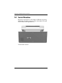
1
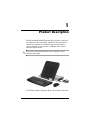
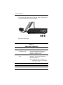
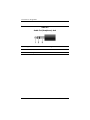
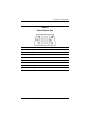
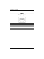
Maintenance and Service
Guide
HP xb3000 Notebook Expansion Base
Document Part Number: 416285-002
July 2007
This guide is a troubleshooting reference used for maintaining a
nd servicing the HP xb3000 Notebook Expansion Base. It
provides comprehensive information on identifying expansion
base features, components, and spare parts; troubleshooting
problems; and performing disassembly procedures.
© Copyright 2006, 2007 Hewlett-Packard Development Company, L.P.
The information contained herein is subject to change without notice. The
only warranties for HP products and services are set forth in the express
warranty statements accompanying such products and services. Nothing
herein should be construed as constituting an additional warranty. HP shall
not be liable for technical or editorial errors or omissions contained herein.
Maintenance and Service Guide
HP xb3000 Notebook Expansion Base
Second Edition: July 2007
First Edition: July 2006
Document Part Number: 416285-002
Contents
1 Product Description
1.1
1.2
1.3
1.4
1.5
1.6
1.7
Features . . . . . . . . . . . . . . . . . . . . . . . . . . . . . . . . . . . 1–3
External Components . . . . . . . . . . . . . . . . . . . . . . . . 1–4
Wireless Accessories (Select Models Only) . . . . . . 1–10
Design Overview. . . . . . . . . . . . . . . . . . . . . . . . . . . 1–11
Using the Expansion Base. . . . . . . . . . . . . . . . . . . . 1–12
Using the HP Expansion Accessory Adapter . . . . . 1–20
Synchronizing Wireless Devices
(Select Models Only) . . . . . . . . . . . . . . . . . . . . . . . 1–23
2 Troubleshooting
2.1 Before Replacing Parts . . . . . . . . . . . . . . . . . . . . . . . 2–1
2.2 Problems and Solutions. . . . . . . . . . . . . . . . . . . . . . . 2–2
3 Illustrated Parts Catalog
3.1
3.2
3.3
3.4
3.5
Serial Number Location . . . . . . . . . . . . . . . . . . . . . .
Expansion Base Major Components . . . . . . . . . . . . .
Wireless Components . . . . . . . . . . . . . . . . . . . . . . . .
Hard Drive Components . . . . . . . . . . . . . . . . . . . . . .
Sequential Part Number Listing . . . . . . . . . . . . . . . .
Maintenance and Service Guide
3–1
3–2
3–4
3–5
3–6
iii
Contents
4 Removal and Replacement Preliminaries
4.1
4.2
4.3
4.4
4.5
4.6
4.7
Tools Required . . . . . . . . . . . . . . . . . . . . . . . . . . . . .
Service Considerations . . . . . . . . . . . . . . . . . . . . . . .
Preventing Damage to Removable Drives . . . . . . . .
Preventing Electrostatic Damage . . . . . . . . . . . . . . .
Packaging and Transporting Precautions . . . . . . . . .
Workstation Precautions . . . . . . . . . . . . . . . . . . . . . .
Grounding Equipment and Methods . . . . . . . . . . . . .
4–1
4–2
4–3
4–4
4–5
4–6
4–7
5 Removal and Replacement Procedures
5.1
5.2
5.3
5.4
Serial Number . . . . . . . . . . . . . . . . . . . . . . . . . . . . . .
Disassembly Sequence Chart . . . . . . . . . . . . . . . . . .
Preparing the Expansion Base for Disassembly . . . .
Installing an Optional Hard Drive. . . . . . . . . . . . . . .
5–2
5–3
5–3
5–4
6 Specifications
A Screw Listing
B Connector Pin Assignments
C Power Cord Set Requirements
Index
iv
Maintenance and Service Guide
1
Product Description
The HP xb3000 Notebook Expansion Base provides an efficient,
less-cluttered work environment, improved cable management,
and wireless peripherals. It eliminates the need to purchase a
separate monitor, external speakers, USB hub, and a wireless
keyboard and mouse kit.
wireless keyboard and mouse kit are available in select
✎ The
countries and regions.
HP xb3000 Notebook Expansion Base with Wireless Components
Maintenance and Service Guide
1–1
Product Description
The HP xb3000 Notebook Expansion Base is compatible with
the following platforms:
■
HP Pavilion dv9000 Notebook PC
■
HP Pavilion dv6000 Notebook PC
■
HP Pavilion dv2000 Notebook PC
■
HP Pavilion tx1000 Entertainment PC
■
Compaq Presario V6000 Notebook PC
■
Compaq Presario V3000 Notebook PC
The following computers require use of the HP Expansion
Accessory Adapter to connect to the expansion base:
1–2
■
HP Pavilion dv8300 Notebook PC
■
HP Pavilion dv8000 Notebook PC
■
HP Pavilion dv5000 Notebook PC
■
HP Pavilion dv4000 Notebook PC
■
HP Pavilion dv1400 Entertainment Notebook PC
■
HP Pavilion ze2000Notebook PC
■
HP Compaq nx4820 Notebook PC
■
HP Special Edition L2000 Notebook PC
■
Compaq Presario V5000 Notebook PC
■
Compaq Presario V4000 Notebook PC
■
Compaq Presario V2000 Notebook PC
■
Compaq Presario M2000 Notebook PC
Maintenance and Service Guide
Product Description
1.1 Features
■
Adjustable height
■
External AC adapter (charges docked computer)
■
Support for display panel sizes up to 43 cm (17 inches) wide
■
Altec/Lansing ported speakers
■
Wireless keyboard, mouse, receiver (select models only)
■
Hard drive bay and power connector
■
Security slots (2)
■
Infrared pass-through support
■
Lights (power, good dock, mute)
■
Volume control wheel with mute button
■
Connectors:
❏ Expansion cable
❏ Audio-out (headphone) connector
❏ Audio-in (microphone) connector
❏ Universal Serial Bus (USB) 2.0 connectors (6)
❏ Power connector
❏ Component video jacks
❏ S-Video-out
❏ Composite video jack
❏ S/PDIF (Sony/Philips Digital Interface) audio connector
❏ External monitor port
❏ RJ-45/Ethernet port
❏ Hard drive power connector
Maintenance and Service Guide
1–3
Product Description
1.2 External Components
The external components on the front panel of the expansion base
are shown below and described in Table 1-1.
Front Components
Table 1-1
Front Components
Item
Component
Function
1
Speakers (2)
Produce stereo expansion base sound.
2
Power button
Turns on the computer.
1–4
Maintenance and Service Guide
Product Description
Table 1-1
Front Components (Continued)
Item
Component
Function
3
Power light
On: The expansion base is connected to
AC power.
4
Mute button
Mutes and restores expansion base sound.
5
Volume down button
Blinking: The volume scroll zone is being
used to decrease expansion base sound.
6
Volume up button
Blinking: The volume scroll zone is being
used to increase expansion base sound.
7
Consumer infrared
lens
Detects the computer remote control
infrared signal.
8
Volume scroll zone
Adjusts volume. Slide your finger to the left
to decrease volume and to the right to
increase volume.
■ To decrease volume, slide your finger to
the left, tap the left half of the scroll zone,
or hold your finger over the left half of the
scroll zone.
■ To increase volume, slide your finger to
the right, tap the right half of the scroll
zone, or hold your finger over the right
half of the scroll zone.
Maintenance and Service Guide
1–5
Product Description
The external components on the right side of the expansion base
are shown below and described in Table 1-2.
Right-Side Components
Table 1-2
Right-Side Components
Item
Component
Function
1
Audio-out
(headphone) jack
Produces expansion base sound when
connected to optional powered stereo
speakers, headphones, ear buds, a
headset, or television audio.
2
Audio-in (microphone)
jack
Connects an optional computer headset
microphone, stereo array microphone, or
monaural microphone.
expansion base speakers are
✎ The
muted when a device is connected to
the headphone jack.
3
USB ports (2)*
Connect optional USB devices.
*There are 4 additional USB ports on the rear panel of the expansion base.
1–6
Maintenance and Service Guide
Product Description
The external component on the left side of the expansion base is
shown below and described in Table 1-3.
Left-Side Components
Table 1-3
Left-Side Component
Component
Function
Hard drive bay
Holds an optional internal hard drive.
Maintenance and Service Guide
1–7
Product Description
The expansion base rear panel components are shown below and
described in Table 1-4.
Rear Panel Components
Table 1-4
Rear Panel Components
Item
Component
Function
1
Power connector
Connects the expansion base to the
computer AC adapter.
2
USB ports (4)*
Connect optional USB devices.
3
Component video jacks
Connect an optional component video
device.
4
S-Video-out jack
Connects an optional S-Video device such
as a television, VCR, camcorder,
overhead projector, or video capture card.
1–8
Maintenance and Service Guide
Product Description
Table 1-4
Rear Panel Components (Continued)
Item
Component
Function
5
Composite video jack
Connects an optional composite video
device.
6
S/PDIF (Sony/Philips
Digital Interface) digital
audio jack
Connects an optional compatible
audio/video receiver through a digital
coaxial cable (purchased separately).
7
External monitor port
Connects an optional external VGA
monitor or projector.
8
RJ-45 (network) jack
Connects an Ethernet cable from the
expansion base to an RJ-45 wall jack.
9
Hard drive power
connector
Connects the power cord for the optional
internal hard drive.
10
Security cable slot
Attaches an optional security cable to the
expansion base.
security cable is designed to
✎ The
act as a deterrent, but it may not
prevent the expansion base from
being mishandled or stolen.
11
Hard drive carrier screw
Secures the hard drive carrier for the
optional internal hard drive.
12
Expansion cable
Connects the expansion base to a
computer.
13
Connection indicator
light
On: The computer is connected correctly.
*There are 2 additional USB ports on the right side of the expansion base.
Maintenance and Service Guide
1–9
Product Description
1.3 Wireless Accessories
(Select Models Only)
On select models, the wireless components shown below and
described in Table 1-5 are included with the expansion base.
Wireless Accessories
Table 1-5
Keyboard Components
Item
Component
Function
1
Receiver
Connects to a USB port on the expansion
base. Enables connection between the
expansion base and the wireless keyboard
and mouse.
2
Wireless keyboard
Connects to the expansion base without
a cable.
3
Wireless mouse
Connects to the expansion base without
a cable.
4
Batteries
To be inserted into the wireless keyboard
and mouse.
1–10
Maintenance and Service Guide
Product Description
1.4 Design Overview
This section presents a design overview of key parts and features
of the expansion base. Refer to Section , “Illustrated Parts
Catalog,” to identify replacement parts, and Section , “Removal
and Replacement Procedures,” for disassembly steps.
The expansion base provides the following device connections:
Ä
■
Expansion cable
■
S/PDIF (Sony/Philips Digital Interface) audio connector
■
Audio-out (headphone) jack
■
Composite out
■
RJ-11 (modem) connection (from wall to expansion base)
■
RJ-11 (modem) connection (from expansion base to
computer)
■
RJ-45 (network) port
■
USB 2.0 connectors (3)
■
S-Video-out
■
Serial port
CAUTION: To properly ventilate the expansion base, allow at least a
7.6-cm (3-inch) clearance on the left and right sides of the unit.
The computer uses an electric fan for ventilation. The fan is
controlled by a temperature sensor and is designed to turn on
automatically when high temperature conditions exist. These
conditions are affected by high external temperatures, system
power consumption, power management/battery conservation
configurations, battery fast charging, and software.
Maintenance and Service Guide
1–11
Product Description
1.5 Using the Expansion Base
Adjusting the Expansion Base
The expansion base must be upright before a computer is
attached.
To adjust the expansion base to an upright position:
»
Lift the upper panel to the appropriate height.
Adjusting the Expansion Base
1–12
Maintenance and Service Guide
Product Description
To lower the expansion base:
1. Pull out the handles on each side of the expansion base 1.
2. Grasp the handles and lower the upper panel of the
expansion base 2.
Lowering the Expansion Base
Maintenance and Service Guide
1–13
Product Description
Connecting to AC Power
Å
1–14
WARNING: To reduce the risk of electric shock or damage to your
equipment:
■ Plug the power cord into an electrical outlet that is easily accessible
at all times.
■ Disconnect power from the product by unplugging the power cord
from the electrical outlet.
■ If provided with a 3-pin attachment plug on your power cord, plug
the cord into a grounded (earthed) 3-pin outlet. Do not disable the
power cord grounding pin; for example, by using a 2-pin adapter.
The grounding pin is an important safety feature.
Maintenance and Service Guide
Product Description
1. Connect the computer AC adapter to the power connector on
the expansion base 1.
2. Connect the AC power cord to the AC adapter 2.
3. Connect the AC power cord to the AC outlet 3.
Connecting the Expansion Base to AC Power
✎ Power cords and power outlets vary by region and country.
AC adapter is included with the computer or purchased
✎ The
separately.
Maintenance and Service Guide
1–15
Product Description
Connecting the Computer
This section applies to the following computers:
■ HP Pavilion dv9000 Notebook PC
■ HP Pavilion dv6000 Notebook PC
■ HP Pavilion dv2000 Notebook PC
■ HP Pavilion tx1000 Entertainment PC
■ Compaq Presario V6000 Notebook PC
■ Compaq Presario V3000 Notebook PC
Refer to Section 1.6, “Using the HP Expansion Accessory
Adapter,” if you are connecting a computer that requires the
HP Expansion Accessory Adapter.
1. Turn the expansion base upright.
2. Open the computer.
1–16
Maintenance and Service Guide
Product Description
3. Slide the computer into the expansion base with the keyboard
facing you.
Sliding the Computer into the Expansion Base
computer is held in place by a buffer pad, which prevents
✎ The
the computer from shifting out of its proper position in the
expansion base.
Maintenance and Service Guide
1–17
Product Description
4. Move the expansion cable to either side of the
expansion base, depending on where the expansion port on
your computer is located.
location of the expansion port on your computer varies by
✎ The
computer series and model.
Extracting the Expansion Cable
important to position the cable correctly, so that the cable
✎ Itcanis move
freely. A cable guide assists you in positioning the
cable.
1–18
Maintenance and Service Guide
Product Description
5. Press the buttons on the sides of the expansion cable 1.
6. Connect the expansion cable to the computer 2, matching the
icon on the computer expansion port with the icon on the end
of the expansion cable.
Ä
CAUTION: To prevent damage to the expansion port, be sure to correctly
align the expansion cable to the expansion port on the computer.
expansion port may also be called “expansion port 3” in
✎ The
the computer user guide.
Connecting the Expansion Cable
7. If the computer is not already turned on, press the power
button on the computer to turn it on.
If the computer connection was made properly, the connection
indicator light on the expansion base will light up solid blue.
the computer is connected to the expansion base, the
✎ After
internal computer speakers are disabled and the expansion base
speakers are activated.
Maintenance and Service Guide
1–19
Product Description
1.6 Using the HP Expansion Accessory
Adapter
The following computers require use of the HP Expansion
Accessory Adapter to connect the computer to the expansion
base:
1–20
■
HP Pavilion dv8300 Notebook PC
■
HP Pavilion dv8000 Notebook PC
■
HP Pavilion dv5000 Notebook PC
■
HP Pavilion dv4000 Notebook PC
■
HP Pavilion dv1400 Entertainment Notebook PC
■
HP Pavilion ze2000Notebook PC
■
HP Compaq nx4820 Notebook PC
■
HP Special Edition L2000 Notebook PC
■
Compaq Presario V5000 Notebook PC
■
Compaq Presario V4000 Notebook PC
■
Compaq Presario V2000 Notebook PC
■
Compaq Presario M2000 Notebook PC
Maintenance and Service Guide
Product Description
To connect a computer using the HP Expansion Accessory
Adapter:
1. Connect the HP Expansion Accessory Adapter to
the computer.
Connecting the HP Expansion Accessory Adapter
2. Slide the computer into the expansion base and gently pull
the expansion cable from its docked location.
Maintenance and Service Guide
1–21
Product Description
3. Connect the expansion cable to the HP Expansion Accessory
Adapter.
Connecting the Expansion Cable to the HP Expansion Accessory
Adapter
1–22
Maintenance and Service Guide
Product Description
1.7 Synchronizing Wireless Devices
(Select Models Only)
1. Press the connect button on the receiver 1.
2. While the button on the receiver is flashing, press the connect
button on the bottom of the keyboard 2.
Synchronizing the Wireless Receiver and Wireless Keyboard
3. Turn the keyboard right-side up.
4. Wait 20 seconds.
Maintenance and Service Guide
1–23
Product Description
5. If you are also using the wireless mouse, press the connect
button on the receiver again 1.
6. While the button on the receiver is flashing, press the
connect button on the bottom of the mouse 2.
Synchronizing the Wireless Receiver and Wireless Mouse
7. Turn the mouse right-side up.
8. Wait 20 seconds.
Your wireless keyboard and mouse will now operate while a
notebook is connected to the expansion base.
1–24
Maintenance and Service Guide
2
Troubleshooting
Å
WARNING: Only authorized technicians trained by HP should repair
this equipment. All troubleshooting and repair procedures are detailed
to allow only subassembly-/module-level repair. Because of the
complexity of the individual boards and subassemblies, do not attempt
to make repairs at the component level or modifications to any printed
wiring board. Improper repairs can create a safety hazard. Any
indication of component replacement or printed wiring board
modification may void any warranty or exchange allowances.
This chapter contains troubleshooting information for the
expansion base. Carefully match the symptoms of the
malfunction against the problem description in the
troubleshooting tables to avoid a misdiagnosis. Refer to
Chapter 5 for all removal and replacement procedures.
Follow these guidelines when troubleshooting:
■
Complete the recommended actions in the order in which
they are given.
■
When the problem is resolved, do not complete the remaining
troubleshooting steps.
2.1 Before Replacing Parts
When troubleshooting a problem, check the following list for
possible solutions before replacing parts:
■
Be sure that cables are connected properly to the suspected
defective part.
■
Be sure that all required device drivers are installed on the
computer.
Maintenance and Service Guide
2–1
Troubleshooting
2.2 Problems and Solutions
The following tables list possible problems, the possible cause of
each problem, and the recommended solution.
Table 2-1
Docking Problems and Solutions
Problem
Possible Cause
Solution
The computer is turned
on and properly docked,
but the power light and
docking light are not on.
Power cord is not
plugged into either the
expansion base or the
AC outlet.
Properly plug in
power cord.
Some of the ports or
connectors do not work,
even though the docking
light is turned on.
The computer may be
properly aligned, but is
not fully seated or
docked in the
expansion base.
Lift the computer away
from the expansion base.
Then realign the
computer visual
alignment indicator with
the indicator on the
expansion base, and
then reconnect the
computer. Be sure that
the computer is properly
aligned and seated, and
fully docked by gently
pressing down on the
computer until you hear
a click. If accessories are
attached, they should
now work properly.
2–2
Maintenance and Service Guide
Troubleshooting
Table 2-2
Undocking Problems and Solutions
Problem
Possible Cause
Solution
The computer will not
disconnect from the
expansion base.
The connectors may be
jammed.
Press the eject button all
the way in. If the
computer does not
disconnect, repeat this
procedure to disconnect
the computer.
Ä
The HP/Kensington
Cable Lock is in the
locked position.
Maintenance and Service Guide
Applying
excessive force
may damage
connector pins.
Unlock the lock and then
disconnect the computer.
2–3
Troubleshooting
Table 2-3
External Device Problems and Solutions
Problem
Possible Cause
The print driver was
successfully installed,
but I am unable to print.
The wrong print
processor may be
selected.
A new device is not
recognized as part of
the system.
The computer may be
properly aligned, but is
not fully seated or
docked in the
expansion base.
2–4
Solution
1. Select Start >
Printers and Faxes.
2. Right-click the
printer icon and click
Properties.
3. Click the Advanced
tab and click Print
Processor.
4. Change the print
processor to
WINPRINT.
5. Click OK.
Lift the computer away
from the expansion base.
Then realign the
computer visual
alignment indicator with
the indicator on the
expansion base, and
reconnect the computer.
Be sure that the
computer is properly
aligned and seated, and
fully docked by gently
pressing down on the
computer until you hear
a click. If accessories are
attached, they should
now be recognized by
the system.
Maintenance and Service Guide
Troubleshooting
Table 2-3
External Device Problems and Solutions (Continued)
Problem
Possible Cause
Solution
A new device is not
recognized as part of
the system. (Continued)
The device cable or
power cord is loose.
■ Be sure that all cables
are securely
connected to the
device and the
expansion base.
■ Be sure that all power
cords are securely
connected to the
device or
expansion base and
to an AC outlet.
The device was
connected while
the system was on.
Turn off the computer,
turn on the device (if
applicable), and then
turn on the computer.
Cabling is incorrect.
Be sure that the device
cable is in the correct
connector on the
expansion base.
You may need to install
device drivers on the
computer.
Install drivers according
to the device
manufacturer’s
instructions.
Maintenance and Service Guide
2–5
Troubleshooting
Table 2-4
Optical Drive Problems and Solutions
Problem
Possible Cause
Solution
The system cannot read
the optical disc.
The disc is not properly
seated in the media tray.
Remove the disc, reseat
it in the media tray, and
then close the
media tray.
The disc is upside down.
Remove the disc, turn it
over, and then close the
media tray.
The disc may be dirty or
scratched.
Replace the disc.
The disc is not properly
seated in the media tray.
Turn off the computer,
and then manually eject
the media tray.
There is no power to the
expansion base.
Turn on power to the
system, and then eject
the disc.
The system cannot eject
the media tray.
Table 2-5
MultiBay II Problems and Solutions
Problem
Possible Cause
Solution
The MultiBay II drive is
not recognized.
The drive is not properly
inserted in the
MultiBay II.
Remove the MultiBay II
drive, and then
reinsert it.
The drive was inserted
while the power was on.
Restart the computer
while the drive is in the
MultiBay II.
2–6
Maintenance and Service Guide
Troubleshooting
Getting More Information
■
For comprehensive information about your computer, as well
as governmental agency and safety information about the use
of your computer, access the Help and Support Center by
selecting Start > Help and Support.
■
The HP Web site (http://www.hp.com) provides product news
and software updates.
Customer Care
If you cannot solve a problem using the troubleshooting tips in
this chapter, you may need to contact Customer Care.
For the fastest possible resolution of your problem, have the
following information available when you call or e-mail:
■
The computer and expansion base model types
■
Serial numbers for the computer and expansion base
■
Dates the computers and expansion base were purchased
■
Conditions under which the problem occurred
■
Error messages that have been displayed
■
Hardware configuration of the computer
■
Hardware and software you are using
■
The manufacturer and model of the printer or other
accessories connected to the computer and expansion base
■
Configuration settings, including contents of the system files
To access Customer Care, visit the HP Web site at
http://www.hp.com/support.
Maintenance and Service Guide
2–7
Troubleshooting
2–8
Maintenance and Service Guide
3
Illustrated Parts Catalog
This chapter provides an illustrated parts breakdown and a
reference for spare part numbers and option part numbers.
3.1 Serial Number Location
When ordering parts or requesting information, provide the
expansion base serial number and model number located on the
bottom of the base plate.
Serial Number Location
Maintenance and Service Guide
3–1
Illustrated Parts Catalog
3.2 Expansion Base
Major Components
HP Notebook Expansion Base Major Components
3–2
Maintenance and Service Guide
Illustrated Parts Catalog
Table 3-1
Spare Parts: Expansion Base Major Components
Item
Description
Spare Part
Number
1
HP xb3000 Notebook Expansion Base
417329-001
2
HP Expansion Accessory Adapter
417330-001
3
Hard drive power cords
For use in:
Australia
The United States
383496-011
383496-001
Hard drive AC adapters (not illustrated)
30W, California Energy Commission (CEC) compliant
30W, non-CEC compliant
Maintenance and Service Guide
434411-001
404477-001
3–3
Illustrated Parts Catalog
3.3 Wireless Components
Wireless Components
Table 3-2
Spare Parts: Wireless Components
Item
Description
Spare Part
Number
1
Wireless receiver
417335-001
2
Wireless keyboard
For use in:
Asia Pacific
Brazil
Korea
3
3–4
Wireless mouse
417333-371
417333-201
417333-AD1
Latin America
The United States
417333-161
417333-001
417334-001
Maintenance and Service Guide
Illustrated Parts Catalog
3.4 Hard Drive Components
HP Notebook Expansion Base Hard Drive Components
Table 3-3
Spare Parts: Hard Drive Components
Item
Description
Spare Part
Number
1
Hard drive—300-GB,* Serial ATA
417703-001
2
Hard drive carrier
417700-001
3
Hard drive AC adapters (not illustrated)
30W, CEC compliant
30W, non-CEC compliant
434411-001
404477-001
*Total storage capacity is 300 billion bytes (for hard drives, 1 GB = 1 billion
bytes); actual accessible capacity is less.
Maintenance and Service Guide
3–5
Illustrated Parts Catalog
3.5 Sequential Part Number Listing
Table 3-4
Spare Parts: Sequential Part Number Listing
Spare Part
Number
Description
383496-001
Power cord for use in the United States
383496-011
Power cord for use in Australia
404477-001
30-watt, non-CEC compliant hard drive AC adapter
417329-001
Expansion base
417330-001
HP Expansion Accessory Adapter
417333-001
Wireless keyboard for use in the United States
417333-161
Wireless keyboard for use in Latin America
417333-201
Wireless keyboard for use in Brazil
417333-371
Wireless keyboard for use in Asia Pacific
417333-AD1
Wireless keyboard for use in Korea
417334-001
Wireless mouse
417335-001
Wireless receiver
417700-001
Hard drive carrier
417703-001
300-GB, serial ATA hard drive
434411-001
30-watt, CEC compliant hard drive AC adapter
3–6
Maintenance and Service Guide
4
Removal and Replacement
Preliminaries
This chapter provides essential information for proper and
safe removal and replacement service.
4.1 Tools Required
You will need the following tools to complete the removal and
replacement procedures:
■ Magnetic screwdriver
■ Phillips P0 and P1 screwdrivers
■ Flat-bladed screwdriver
Maintenance and Service Guide
4–1
Removal and Replacement Preliminaries
4.2 Service Considerations
The following sections include some of the considerations
that you should keep in mind during disassembly and assembly
procedures.
you remove each subassembly from the expansion base,
✎ As
place the subassembly (and all accompanying screws) away
from the work area to prevent damage.
Plastic Parts
Using excessive force during disassembly and reassembly can
damage plastic parts. Use care when handling the plastic parts.
Apply pressure only at the points designated in the maintenance
instructions.
Cables and Connectors
Ä
CAUTION: When servicing the expansion base, ensure that cables
are placed in their proper locations during the reassembly process.
Improper cable placement can damage the expansion base.
Cables must be handled with extreme care to avoid damage.
Apply only the tension required to unseat or seat the cables
during removal and insertion. Handle cables by the connector
whenever possible. In all cases, avoid bending, twisting, or
tearing cables. Ensure that cables are routed in such a way that
they cannot be caught or snagged by parts being removed or
replaced. Handle flex cables with extreme care; these cables
tear easily.
4–2
Maintenance and Service Guide
Removal and Replacement Preliminaries
4.3 Preventing Damage to
Removable Drives
Removable drives are fragile components that must be handled
with care. To prevent damage to the expansion base, damage to a
removable drive, or loss of information, observe the following
precautions:
■ Before removing or inserting a hard drive, shut down the
system (computer and expansion base). If you are unsure
whether the system is off or in hibernation, turn the system on,
and then shut it down through the operating system.
■ Before removing a diskette drive or optical drive, ensure that
a diskette or disc is not in the drive and ensure that the optical
drive tray is closed.
■ Before handling a drive, ensure that you are discharged of
static electricity. While handling a drive, avoid touching the
connector.
■ Handle drives on surfaces covered with at least one inch of
shock-proof foam.
■ Avoid dropping drives from any height onto any surface.
■ After removing a hard drive or MultiBay II device, place it in a
static-proof bag.
■ Avoid exposing a hard drive to products that have magnetic
fields, such as monitors or speakers.
■ Avoid exposing a drive to temperature extremes or liquids.
■ If a drive must be mailed, place the drive in a bubble pack
mailer or other suitable form of protective packaging and label
the package, “FRAGILE: Handle With Care.”
Maintenance and Service Guide
4–3
Removal and Replacement Preliminaries
4.4 Preventing Electrostatic Damage
Many electronic components are sensitive to electrostatic
discharge (ESD). Circuitry design and structure determine the
degree of sensitivity. Networks built into many integrated circuits
provide some protection, but in many cases, the discharge
contains enough power to alter device parameters or melt
silicon junctions.
A sudden discharge of static electricity from a finger or other
conductor can destroy static-sensitive devices or microcircuitry.
Often the spark is neither felt nor heard, but damage occurs.
An electronic device exposed to electrostatic discharge might not
be affected at all and can work perfectly throughout a normal
cycle. Or the device might function normally for a while, then
degrade in the internal layers, reducing its life expectancy.
4–4
Maintenance and Service Guide
Removal and Replacement Preliminaries
4.5 Packaging and Transporting
Precautions
Use the following grounding precautions when packaging and
transporting equipment:
■ To avoid hand contact, transport products in static-safe
containers, such as tubes, bags, or boxes.
■ Protect all electrostatic-sensitive parts and assemblies with
conductive or approved containers or packaging.
■ Keep electrostatic-sensitive parts in their containers until
the parts arrive at static-free workstations.
■ Place items on a grounded surface before removing items
from their containers.
■ Always be properly grounded when touching a sensitive
component or assembly.
■ Store reusable electrostatic-sensitive parts from assemblies
in protective packaging or nonconductive foam.
■ Use transporters and conveyors made of antistatic belts and
roller bushings. Ensure that mechanized equipment used for
moving materials is wired to ground and that proper materials
are selected to avoid static charging. When grounding is not
possible, use an ionizer to dissipate electric charges.
Maintenance and Service Guide
4–5
Removal and Replacement Preliminaries
4.6 Workstation Precautions
Use the following grounding precautions at workstations:
■ Cover the workstation with approved static-shielding material
(refer to Table 4-2, “Static-Shielding Materials”).
■ Use a wrist strap connected to a properly grounded work
surface and use properly grounded tools and equipment.
■ Use conductive field service tools, such as cutters,
screwdrivers, and vacuums.
■ When using fixtures that must directly contact dissipative
surfaces, only use fixtures made of static-safe materials.
■ Keep the work area free of nonconductive materials, such
as ordinary plastic assembly aids and Styrofoam.
■ Handle electrostatic-sensitive components, parts, and
assemblies by the case or PCM laminate. Handle these
items only at static-free workstations.
■ Avoid contact with pins, leads, or circuitry.
■ Turn off power and input signals before inserting or removing
connectors or test equipment.
4–6
Maintenance and Service Guide
Removal and Replacement Preliminaries
4.7 Grounding Equipment and
Methods
Grounding equipment must include either a wrist strap or a
foot strap at a grounded workstation.
■ When seated, wear a wrist strap connected to a grounded
system. Wrist straps are flexible straps with a minimum of
one megohm ±10% resistance in the ground cords. To provide
proper ground, wear a strap snugly against the skin at all times.
On grounded mats with banana-plug connectors, use alligator
clips to connect a wrist strap.
■ When standing, use foot straps and a grounded floor mat.
Foot straps (heel, toe, or boot straps) can be used at standing
workstations and are compatible with most types of shoes
or boots. On conductive floors or dissipative floor mats, use
foot straps on both feet with a minimum of one megohm
resistance between the operator and ground. To be effective,
the conductive strips must be worn in contact with the skin.
Other grounding equipment recommended for use in preventing
electrostatic damage includes
■ Antistatic tape.
■ Antistatic smocks, aprons, and sleeve protectors.
■ Conductive bins and other assembly or soldering aids.
■ Nonconductive foam.
■ Conductive tabletop workstations with ground cords of
one megohm resistance.
■ Static-dissipative tables or floor mats with hard ties to
the ground.
■ Field service kits.
■ Static awareness labels.
■ Material-handling packages.
■ Nonconductive plastic bags, tubes, or boxes.
■ Metal tote boxes.
■ Electrostatic voltage levels and protective materials.
Maintenance and Service Guide
4–7
Removal and Replacement Preliminaries
Table 4-1 shows how humidity affects the electrostatic voltage
levels generated by different activities.
Table 4-1
Typical Electrostatic Voltage Levels
Relative Humidity
Event
10%
40%
55%
Walking across carpet
35,000 V
15,000 V
7,500 V
Walking across vinyl floor
12,000 V
5,000 V
3,000 V
Motions of bench worker
6,000 V
800 V
400 V
Removing DIPS from plastic tube
2,000 V
700 V
400 V
Removing DIPS from vinyl tray
11,500 V
4,000 V
2,000 V
Removing DIPS from Styrofoam
14,500 V
5,000 V
3,500 V
Removing bubble pack from PCB
26,500 V
20,000 V
7,000 V
Packing PCBs in foam-lined box
21,000 V
11,000 V
5,000 V
✎ A product can be degraded by as little as 700 V.
Table 4-2 lists the shielding protection provided by antistatic
bags and floor mats.
Table 4-2
Static-Shielding Materials
Material
Use
Voltage Protection Level
Antistatic plastic
Bags
1,500 V
Carbon-loaded plastic
Floor mats
7,500 V
Metallized laminate
Floor mats
5,000 V
4–8
Maintenance and Service Guide
5
Removal and Replacement
Procedures
This chapter provides removal and replacement procedures.
There are as many as 7 screws, in 3 different sizes, that must be
removed, replaced, or loosened when servicing the
expansion base. Make special note of screw size and location
during removal and replacement.
Refer to Appendix A, “Screw Listing,” for detailed information
on screw sizes, locations, and usage.
Maintenance and Service Guide
5–1
Removal and Replacement Procedures
5.1 Serial Number
Report the expansion base serial number to HP when requesting
information or ordering spare parts. The serial number is located
on the bottom of the expansion base.
Serial Number Location
5–2
Maintenance and Service Guide
Removal and Replacement Procedures
5.2 Disassembly Sequence Chart
Use the chart below to determine the section number to be
referenced when removing computer components.
Disassembly Sequence Chart
Section
Description
5.3
Preparing the Expansion Base
for Disassembly
5.4
Installing an Optional Hard Drive
Hard drive carrier
1
Hard drive rear panel
2
Hard drive
4
# of Screws Removed
5.3 Preparing the Expansion Base
for Disassembly
Perform the following steps before disassembling the
expansion base:
1. If the computer is in the expansion base, turn off the
computer and disconnect the expansion cable from
the computer.
2. Remove the computer from the expansion base.
3. Disconnect the AC adapter and all external devices from
the expansion base.
Maintenance and Service Guide
5–3
Removal and Replacement Procedures
5.4 Installing an Optional Hard Drive
You can install an optional hard drive into the expansion base for
extra storage capacity.
Installing an optional hard drive may require the following
components:
Hard Drive Components
Hard Drive Components
Component
Description
1
Hard drive
Provides optional internal storage.
2
Hard drive power cord
Connects to an AC wall outlet.
3
Hard drive power adapter
Connects to the hard drive power
connector.
4
Screws (6)
Secure the optional internal hard
drive to the hard drive carrier.
5
Hard drive carrier
Holds the optional internal hard
drive. (In some configurations, the
hard drive carrier is preinstalled.)
✎ Depending on configuration, some components are not required.
5–4
Maintenance and Service Guide
Removal and Replacement Procedures
1. Remove the Phillips PM2.5×7.0 screw 1 that secures the
hard drive carrier to the expansion base.
2. Remove the hard drive carrier 2 from the expansion base.
Removing the Hard Drive Carrier
Maintenance and Service Guide
5–5
Removal and Replacement Procedures
3. Remove the two Phillips PM2.5×5.0 screws 1 that secure the
hard drive carrier rear panel to the hard drive carrier.
4. Remove the hard drive carrier rear panel 2 from the
hard drive carrier.
Removing the Hard Drive Carrier Rear Panel
5–6
Maintenance and Service Guide
Removal and Replacement Procedures
5. With the hard drive connectors toward you, insert the
hard drive 1 into the hard drive carrier.
6. Install the four Phillips PM3.0×4.0 screws 2 to secure the
hard drive to the hard drive carrier.
Inserting the Hard Drive into the Hard Drive Carrier
Maintenance and Service Guide
5–7
Removal and Replacement Procedures
7. Connect the hard drive data cable 1 and the hard drive
power cable 2 to the appropriate connectors on the back of
the hard drive.
Connecting the Hard Drive Carrier Rear Panel
5–8
Maintenance and Service Guide
Removal and Replacement Procedures
8. Insert the hard drive carrier 1 into the expansion base
hard drive bay.
9. Install the Phillips PM2.5×5.0 screw 2 to secure the
hard drive carrier to the expansion base.
Installing the Hard Drive Carrier
Maintenance and Service Guide
5–9
Removal and Replacement Procedures
10. Connect the hard drive power adapter 1 to the hard drive
power connector on the expansion base rear panel.
11. Connect the power cord to the hard drive power adapter 2,
and then connect the power cord to the wall outlet 3.
Connecting the Hard Drive AC Adapter
more information on the hard drive, refer to the instructions
✎ For
that came with the hard drive.
To remove the optional internal hard drive, reverse the installation
procedures.
5–10
Maintenance and Service Guide
6
Specifications
This chapter provides physical and performance specifications.
Table 6-1
Expansion Base
Dimensions
Length
Width
Height
Weight
With hard drive
Without hard drive
45.6 cm
32.8 cm
12.2 cm
17.9 in
12.9 in
4.8 in
5.25 kg
4.93 kg
11.5 lb
10.9 lb
10°C to 35°C
-20°C to 60°C
50°F to 95°F
-4°F to 140°F
Temperature
Operating*
Nonoperating
product safety standards specify thermal limits for plastic
✎ Applicable
surfaces. The expansion base operates well within this range of
temperatures.
Relative humidity (noncondensing)
Operating
Nonoperating
Maintenance and Service Guide
10% to 90%
5% to 95%, 38.7°C (101.6°F) maximum
wet bulb temperature
6–1
Specifications
Table 6-2
Hard Drive - 300-GB*
Dimensions
Height
Width
Weight
Interface type
Data transfer rate
Disk to buffer
Interface with or
with IORDY
Logical geometry
25.4 mm
89 mm
499 g
Cylinders
Heads
Sectors
16,383
16
63
AT 16 bit
Total logical
sections
2,001,382
Disk rotational
speed
7200 rpm
Average latency
5.5 ms
Spin-up time
(maximum)
7.0 s
Spin-down time
(maximum)
100 S
45
Mbytes/sec
16.6
Mbytes/sec
Seek times (typical read, including
setting)
Single track
Average
Maximum
Physical geometry
Cylinders
Heads
Sectors
Operating temperature
3 ms
13 ms
24 ms
158,518
4
ID 528-710
OD 998-1216
5°C to 55°C (41°F to 131°F)
restrictions and exclusions apply. Consult Customer Care for
✎ Certain
details.
*Total storage capacity is 300 billion bytes (for hard drives, 1GB = 1 billion
bytes); actual accessible capacity is less. Actual drive specifications may differ
slightly.
6–2
Maintenance and Service Guide
A
Screw Listing
This appendix provides specification and reference information
for the screws used on the expansion base.
Maintenance and Service Guide
A–1
Screw Listing
Table A-1
Phillips PM2.5×7.0 Screw
mm
Color
Qty.
Length
Thread
Head
Width
Black
1
7.0 mm
2.5 mm
5.0 mm
Where used:
One screw that secures the hard drive carrier to the expansion base
(documented in Section 5.4)
Phillips PM2.5×7.0 Screw Location
A–2
Maintenance and Service Guide
Screw Listing
Table A-2
Phillips PM2.5×5.0 Screw
mm
Color
Qty.
Length
Thread
Head
Width
Silver
2
5.0 mm
2.5 mm
5.0 mm
Where used:
2 screws that secure the hard drive carrier rear panel to the hard drive carrier
(documented in Section 5.4)
Phillips PM2.5×5.0 Screw Locations
Maintenance and Service Guide
A–3
Screw Listing
Table A-3
Phillips PM3.0×4.0 Screw
mm
Color
Qty.
Length
Thread
Head
Width
Silver
4
4.0 mm
3.0 mm
5.0 mm
Where used:
4 screws that secure the hard drive to the hard drive carrier (documented in
Section 5.4)
Phillips PM3.0×4.0 Screw Locations
A–4
Maintenance and Service Guide
B
Connector Pin Assignments
Table B-1
Audio-In (Microphone) Jack
Pin
Signal
Pin
Signal
1
Audio signal in
3
Ground
2
Audio signal in
Maintenance and Service Guide
B–1
Connector Pin Assignments
Table B-2
Audio-Out (Headphone) Jack
Pin
Signal
Pin
Signal
1
Audio out, left channel
3
Ground
2
Audio out, right channel
B–2
Maintenance and Service Guide
Connector Pin Assignments
Table B-3
External Monitor Port
Pin
Signal
Pin
Signal
1
Red analog
9
+5 VDC
2
Green analog
10
Ground
3
Blue analog
11
Monitor detect
4
Not connected
12
DDC 2B data
5
Ground
13
Horizontal sync
6
Ground analog
14
Vertical sync
7
Ground analog
15
DDC 2B clock
8
Ground analog
Maintenance and Service Guide
B–3
Connector Pin Assignments
Table B-4
RJ-45 (Network) Jack
Pin
Signal
Pin
Signal
1
Transmit +
5
Unused
2
Transmit –
6
Receive –
3
Receive +
7
Unused
4
Unused
8
Unused
B–4
Maintenance and Service Guide
Connector Pin Assignments
Table B-5
S-Video-Out Jack
Pin
Signal
Pin
Signal
1
TV-Ground
5
TV-CD
2
TV-CVBS
6
TV-Ground
3
TV-Ground
7
TV-YD
4
TV-Ground
Maintenance and Service Guide
B–5
Connector Pin Assignments
Table B-6
Universal Serial Bus
Pin
Signal
Pin
Signal
1
+5 VDC
3
Data +
2
Data –
4
Ground
B–6
Maintenance and Service Guide
C
Power Cord Set Requirements
3-Conductor Power Cord Set
The wide range input feature of the expansion base permits it
to operate from any line voltage from 100 to 120 or 220 to
240 volts AC.
The power cord set included with the expansion base meets the
requirements for use in the country where the equipment
is purchased.
Power cord sets for use in other countries must meet the
requirements of the country where the expansion base is used.
Maintenance and Service Guide
C–1
Power Cord Set Requirements
General Requirements
The requirements listed below are applicable to all countries.
C–2
■
The length of the power cord set must be at least 1.5 m
(5.0 ft) and a maximum of 2.0 m (6.5 ft).
■
All power cord sets must be approved by an acceptable
accredited agency responsible for evaluation in the
country where the power cord set will be used.
■
The power cord sets must have a minimum current capacity
of 10 amps and a nominal voltage rating of 125 or 250 V AC,
as required by each country’s power system.
■
The appliance coupler must meet the mechanical
configuration of an EN 60 320/IEC 320 Standard Sheet C13
connector for mating with the appliance inlet on the back of
the expansion base.
Maintenance and Service Guide
Power Cord Set Requirements
Country-Specific Requirements
3-Conductor Power Cord Set Requirements
Country/Region
Accredited Agency
Applicable Note Number
Australia
EANSW
1
Austria
OVE
1
Belgium
CEBC
1
Canada
CSA
2
Denmark
DEMKO
1
Finland
FIMKO
1
France
UTE
1
Germany
VDE
1
Italy
IMQ
1
Japan
METI
3
✎ NOTES:
1. The flexible cord must be <HAR> Type HO5VV-F, 3-conductor, 1.0 mm²
conductor size. Power cord set fittings (appliance coupler and wall plug)
must bear the certification mark of the agency responsible for evaluation
in the country where it will be used.
2. The flexible cord must be Type SPT-3 or equivalent, No. 18 AWG,
3-conductor. The wall plug must be a two-pole grounding type with a
NEMA 5-15P (15 A, 125 V) or NEMA 6-15P (15 A, 250 V) configuration.
3. The appliance coupler, flexible cord, and wall plug must bear a “T” mark
and registration number in accordance with the Japanese Dentori Law. The
flexible cord must be Type VCT or VCTF, 3-conductor, 1.00 mm² conductor
size. The wall plug must be a two-pole grounding type with a Japanese
Industrial Standard C8303 (7 A, 125 V) configuration.
Maintenance and Service Guide
C–3
Power Cord Set Requirements
3-Conductor Power Cord Set Requirements (Continued)
Country/Region
Accredited Agency
Applicable Note Number
Korea
EK
4
The Netherlands
KEMA
1
Norway
NEMKO
1
People’s Republic
of China
CCC
5
Sweden
SEMKO
1
Switzerland
SEV
1
Taiwan
BSMI
4
United Kingdom
BSI
1
United States
UL
2
✎ NOTES:
1. The flexible cord must be <HAR> Type HO5VV-F, 3-conductor, 1.0 mm²
conductor size. Power cord set fittings (appliance coupler and wall plug)
must bear the certification mark of the agency responsible for evaluation
in the country where it will be used.
2. The flexible cord must be Type SPT-3 or equivalent, No. 18 AWG,
3-conductor. The wall plug must be a two-pole grounding type with a
NEMA 5-15P (15 A, 125 V) or NEMA 6-15P (15 A, 250 V) configuration.
3. The appliance coupler, flexible cord, and wall plug must bear a “T” mark
and registration number in accordance with the Japanese Dentori Law. The
flexible cord must be Type VCT or VCTF, 3-conductor, 1.00 mm² conductor
size. The wall plug must be a two-pole grounding type with a Japanese
Industrial Standard C8303 (7 A, 125 V) configuration.
4. The flexible cord must be Type RVV, 3-conductor, 0.75 mm² conductor size.
Power cord set fittings (appliance coupler and wall plug) must bear
the certification mark of the agency responsible for evaluation in the country
where it will be used.
5. The flexible cord must be Type VCTF, 3-conductor, 0.75 mm² conductor
size. Power cord set fittings (appliance coupler and wall plug) must bear the
certification mark of the agency responsible for evaluation in the country
where it will be used.
C–4
Maintenance and Service Guide
Index
A
audio-in jack
location 1–6
pin assignments B–1
audio-out jack
location 1–6
pin assignments B–2
B
batteries, illustrated 1–10
C
cables, service considerations
4–2
component video jacks 1–8
components
front 1–4
left-side 1–7
rear panel 1–8
right-side 1–6
composite video jack 1–9
connection indicator light 1–9
connector pin assignments
audio-in jack B–1
audio-out jack B–2
external monitor port B–3
headphone jack B–2
microphone jack B–1
monitor port B–3
Maintenance and Service Guide
network jack B–4
RJ-45 jack B–4
S-Video-out jack B–5
Universal Serial Bus (USB)
port B–6
connectors, service
considerations 4–2
consumer infrared lens 1–5
D
design overview 1–11
disassembly sequence chart
5–3
drives, preventing damage 4–3
E
electrostatic discharge 4–4,
4–8
expansion accessory adapter
connecting 1–20
spare part number 3–3, 3–6
expansion base
components 3–2
spare part number 3–3, 3–6
specifications 6–1
expansion cable 1–9
external monitor port
location 1–9
pin assignments B–3
Index–1
Index
F
spare part numbers 3–4,
3–6
synchronizing 1–23
features 1–3
front components 1–4
G
L
grounding equipment and
methods 4–7
left-side components 1–7
H
microphone jack
location 1–6
pin assignments B–1
monitor port
location 1–9
pin assignments B–3
mouse
illustrated 1–10
spare part number 3–4, 3–6
synchronizing 1–24
mute button 1–5
hard drive
installation 5–7
precautions 4–3
spare part number 3–5, 3–6
specifications 6–2
hard drive AC adapter, spare
part numbers 3–3, 3–5, 3–6
hard drive bay 1–7
hard drive carrier
removal 5–5
spare part number 3–5, 3–6
hard drive carrier screw 1–9
hard drive components 3–5
hard drive power connector
1–9
hard drive power cord, spare
part numbers 3–3
headphone jack
location 1–6
pin assignments B–2
HP Expansion Accessory
Adapter
connecting 1–20
spare part number 3–3, 3–6
K
keyboard
illustrated 1–10
Index–2
M
N
network jack
location 1–9
pin assignments B–4
O
optical drive, precautions 4–3
P
packing precautions 4–5
plastic parts 4–2
power button 1–4
power connector 1–8
power cord, set requirements
C–2
power cord, spare part
numbers 3–6
power light 1–5
Maintenance and Service Guide
Index
R
U
rear panel components 1–8
receiver
illustrated 1–10
spare part number 3–4, 3–6
removal
preliminaries 4–1
procedures 5–1
replacement
preliminaries 4–1
procedures 5–1
right-side components 1–6
RJ-45 jack
location 1–9
pin assignments B–4
Universal Serial Bus (USB)
port
location 1–6, 1–8
pin assignments B–6
V
volume button 1–5
volume scroll zone 1–5
W
wireless components 3–4
workstation precautions 4–6
S
S/PDIF digital audio jack 1–9
screw listing A–1
security cable slot 1–9
serial number 3–1, 5–2
service considerations 4–2
speakers 1–4
specifications
expansion base 6–1
hard drive 6–2
static shielding materials 4–8
S-Video-out jack
location 1–8
pin assignments B–5
T
tools required 4–1
transporting precautions 4–5
troubleshooting 2–1
Maintenance and Service Guide
Index–3