1
®
Intel Server Board SE7501WV2
Product Guide
A Guide for Technically Qualified Assemblers of Intel® Identified
Subassemblies/Products
Order Number: C14587-002
Disclaimer
Information in this document is provided in connection with Intel® products. No license, express or implied, by
estoppel or otherwise, to any intellectual property rights is granted by this document. Except as provided in Intel’s
Terms and Conditions of Sale for such products. INTEL ASSUMES NO LIABILITY WHATSOEVER, AND INTEL
DISCLAIMS ANY EXPRESS OR IMPLIED WARRANTY, RELATING TO SALE AND/OR USE OF INTEL
PRODUCTS INCLUDING LIABILITY OR WARRANTIES RELATING TO FITNESS FOR A PARTICULAR PURPOSE,
MERCHANTABILITY, OR INFRINGEMENT OF ANY PATENT, COPYRIGHT OR OTHER INTELLECTUAL
PROPERTY RIGHT. Intel products are not designed, intended or authorized for use in any medical, life saving, or life
sustaining applications or for any other application in which the failure of the Intel product could create a situation
where personal injury or death may occur. Intel may make changes to specifications and product descriptions at any
time, without notice.
Intel and Xeon are trademarks or registered trademarks of Intel Corporation or its subsidiaries in the United States
and other countries.
†
Other names and brands may be claimed as the property of others.
Copyright © 2002, Intel Corporation. All Rights Reserved.
ii
Intel Server Board SE7501WV2 Product Guide
Contents
1 Description.......................................................................................................1
Server Board Features ..........................................................................................................1
Server Board Connector and Component Locations.....................................................2
Back Panel Connectors ................................................................................................3
Processor..............................................................................................................................4
Memory .................................................................................................................................4
PCI Riser Slots......................................................................................................................4
Video.....................................................................................................................................4
SCSI Controller .....................................................................................................................5
ATA-100 Controller ...............................................................................................................5
IDE RAID......................................................................................................................5
Network Controller ................................................................................................................6
NIC Connector and Status LEDs ..................................................................................6
Keyboard and Mouse ............................................................................................................6
RJ-45 Serial Port...................................................................................................................6
ACPI 8
System Management ............................................................................................................8
Baseboard Management Controller ..............................................................................8
Field Replaceable Units and Sensor Data Records ......................................................9
System Event Log ........................................................................................................9
Platform Event Management ........................................................................................9
Emergency Management Port ....................................................................................10
Intel® Server Management .........................................................................................10
Security ...............................................................................................................................11
Intrusion Switch Monitoring.........................................................................................11
Software Locks...........................................................................................................11
Using Passwords........................................................................................................11
Secure Mode ..............................................................................................................12
Summary of Software Security Features.....................................................................13
2 Server Board Installations and Upgrades...................................................15
Tools and Supplies Needed ................................................................................................15
Cautions..............................................................................................................................15
Rearrange the Standoffs .....................................................................................................16
Install the Server Board.......................................................................................................18
Installing or Replacing Processor(s) ....................................................................................19
Installing the Retention Mechanism (RM) ...................................................................20
Installing Processors ..................................................................................................20
Replacing a Processor................................................................................................23
Memory ...............................................................................................................................24
Connect Cables...................................................................................................................25
Replacing the Back up Battery ............................................................................................26
3 POST and BIOS Setup Utilities ....................................................................29
Hot Keys .............................................................................................................................29
Intel Server Board SE7501WV2 Product Guide
iii
Power-On Self-Test (POST)................................................................................................29
Temporarily Changing the Boot Device Priority...........................................................30
The Adaptec SCSISelect Utility ...........................................................................................30
When to Run the Adaptec SCSISelect Utility ..............................................................31
Running the SCSISelect Utility ...................................................................................31
Configuring the Adaptec AIC-7902 SCSI Adapter.......................................................31
The Promise FastBuild* Utility (SE7501WV2 ATA Model Only) ..........................................32
When to Run the Promise FastBuild Utility .................................................................32
Running the Promise FastBuild Utility.........................................................................32
BIOS Setup .........................................................................................................................32
If BIOS Setup Is Inaccessible .....................................................................................33
Starting Setup.............................................................................................................33
Setup Menus ..............................................................................................................33
Upgrading the BIOS ............................................................................................................35
Preparing for the Upgrade ..........................................................................................35
Performing the BIOS Upgrade ....................................................................................36
Changing the BIOS Language ....................................................................................37
4 Configuration Software and Utilities ...........................................................39
System Software Update Sequence ...........................................................................39
Server Configuration Wizard ...............................................................................................39
Direct Platform Control (DPC) Console ...............................................................................40
DPC Console Modes of Operation..............................................................................41
Running the DPC Console..........................................................................................41
Using the System Setup Utility ............................................................................................42
Creating SSU Diskettes ..............................................................................................42
Running the SSU........................................................................................................42
Setting Boot Device Priority ........................................................................................44
Setting Passwords and Security Options ....................................................................44
Viewing the System Event Log ...................................................................................45
Viewing FRU Information............................................................................................46
Viewing Sensor Data Records ....................................................................................46
Updating System Firmware and BIOS ........................................................................47
Managing the Server Remotely ...........................................................................................48
How to Set Up Remote LAN Access...........................................................................48
How to Set Up Remote Modem or Serial Access........................................................49
How to Set Up Paging Alerts ......................................................................................51
How Set Up LAN Alerts ..............................................................................................53
Firmware Update Utility Description ....................................................................................55
How to Run the Firmware Update Utility .....................................................................55
FRU/SDR Load Utility Description .......................................................................................55
How to Use the FRU/SDR Load Utility........................................................................56
Setting a System Asset Tag ................................................................................................58
Creating Diskettes...............................................................................................................58
Installing a Service Partition (Optional)................................................................................59
Saving and Restoring the System Configuration .................................................................60
Using the Intel® Server Management and Intel® SMaRT Tool (Optional) ...........................62
Installing Intel® Server Management ..........................................................................63
Installing Intel® SMaRT Tool ......................................................................................63
iv
Intel Server Board SE7501WV2 Product Guide
5 Solving Problems ..........................................................................................65
Resetting the System ..........................................................................................................65
Initial System Startup ..........................................................................................................65
Checklist 65
Running New Application Software .....................................................................................66
Checklist 66
After the System Has Been Running Correctly ....................................................................66
Checklist 66
More Problem Solving Procedures ......................................................................................67
Monitoring POST ........................................................................................................67
Verifying Proper Operation of Key System Lights .......................................................67
Confirming Loading of the Operating System .............................................................67
Specific Problems and Corrective Actions ...........................................................................68
Power Light Does Not Light ........................................................................................68
No Characters Appear on Screen...............................................................................68
Characters Are Distorted or Incorrect .........................................................................69
System Cooling Fans Do Not Rotate Properly ............................................................69
Diskette Drive Activity Light Does Not Light ................................................................69
CD-ROM Drive Activity Light Does Not Light ..............................................................70
Problems with Application Software............................................................................70
Bootable CD-ROM Is Not Detected ............................................................................70
Problems with Network........................................................................................................70
6 Technical Reference .....................................................................................73
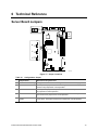
Server Board Jumpers ........................................................................................................73
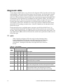
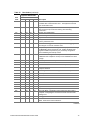
Diagnostic LEDs..................................................................................................................74
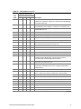
POST Error Codes and Messages ......................................................................................78
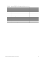
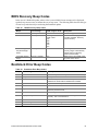
BIOS Recovery Beep Codes ...............................................................................................81
Bootblock Error Beep Codes ...............................................................................................81
7 Regulatory and Integration Information......................................................83
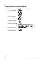
Product Regulatory Compliance ..........................................................................................83
Product Safety Compliance ........................................................................................83
Product EMC Compliance ..........................................................................................83
Product Regulatory Compliance Markings ..................................................................84
Electromagnetic Compatibility Notices ................................................................................85
FCC (USA) .................................................................................................................85
Industry Canada (ICES-003).......................................................................................86
Europe (CE Declaration of Conformity).......................................................................86
Australian Communications Authority (ACA) (C-Tick Declaration of Conformity) ........86
Ministry of Economic Development (New Zealand) Declaration of Conformity............86
BSMI (Taiwan)............................................................................................................86
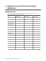
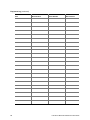
8 Equipment Log and Power Consumption Worksheets .............................87
Equipment Log ....................................................................................................................87
Current Usage.....................................................................................................................89
Calculating Power Consumption.................................................................................89
Intel Server Board SE7501WV2 Product Guide
v
Index ....................................................................................................................91
Figures
Figure 1. Server Board Connector and Component Locations..............................................2
Figure 2. Back Panel Connectors .........................................................................................3
Figure 3. J5A2 Jumper Block for DSR Signal .......................................................................7
Figure 4. Rearrange the Standoffs .....................................................................................17
Figure 5. Installing the Server Board ..................................................................................18
Figure 6. Installing the Processor Retention Mechanism ....................................................20
Figure 7. Raising the Locking Bar.......................................................................................20
Figure 8. Installing Processors ...........................................................................................21
Figure 9. Lower Locking Bar...............................................................................................21
Figure 10. Installing the Heat Sink......................................................................................22
Figure 11. Installing the Heat Sink Clip...............................................................................23
Figure 12. Installing Memory ..............................................................................................24
Figure 13. Connecting Cables ............................................................................................25
Figure 14. Replacing the Back up Battery ..........................................................................27
Figure 15. Jumper Locations ..............................................................................................73
Tables
Table 1.
Table 2.
Table 3.
Table 4.
Table 5.
Table 6.
Table 7.
Table 8.
Table 9.
Table 10.
Table 11.
Table 12.
Table 13.
Table 14.
Table 15.
Table 16.
Table 17.
Table 18.
Table 19.
Table 20.
Table 21.
vi
Server Board Versions ...................................................................................1
Server Board Features ...................................................................................1
Rear Serial 2 Port Adapter Pin-out .................................................................7
Software Security Features ..........................................................................13
POST and BIOS Setup Utilities ....................................................................29
Hot Keys ......................................................................................................29
SCSISelect Navigation Keys ........................................................................31
Adaptec Main Menu .....................................................................................31
Menu for each SCSI Channel.......................................................................32
Exit Menu.....................................................................................................32
Keyboard Commands...................................................................................34
On-Screen Options ......................................................................................34
Command Line Format.................................................................................57
Configuration Jumper ...................................................................................73
Post Codes ..................................................................................................74
Standard POST Error Messages and Codes................................................78
Extended POST Error Messages and Codes ...............................................80
BIOS Recovery Beep Codes ........................................................................81
Bootblock Error Beep Codes ........................................................................81
Power Usage Worksheet 1...........................................................................89
Power Usage Worksheet 2...........................................................................90
Intel Server Board SE7501WV2 Product Guide
1 Description
Server Board Features
The SE7501WV2 is available in either SCSI or ATA hard drive interface versions as described in
Table 1. The features listed in Table 2 are common to both server board versions.
Table 1.
Server Board Versions
Feature
✏
Description
SCSI
Dual channel Ultra320 LVD SCSI accessible at rear panel I/O and internally
ATA
Dual channel ATA 100 RAID
NOTE
The feature set listed in Table 2 only reflects usage with either the 1U
Intel® server chassis, SR1300 or SR2300. Third-party or OEM chassis may
not provide all of the features listed below.
Table 2.
Server Board Features
Feature
Description
Processors
Dual processor slots supporting Intel® Xeon™ processors in an INT3/FCPGA Socket
604 package
Chipset
Intel® chipset E7501:
Supports 533 MHz Front Side Bus (FSB)
MCH memory controller (Northbridge)
ICH3 I/O controller (Southbridge)
P64H2 64-bit I/O hub
Memory
Six dual inline memory module (DIMM) slots support:
• DDR200 or DDR266 compliant, ECC, registered, 72-bit, 168-pin, DIMMs
1
• From 256 MB to 12 GB of memory
Graphics
Integrated onboard ATI RAGE† XL PCI SVGA controller
Video Memory
8 MB SDRAM of video memory
PCI bus
Two PCI riser slots capable of supporting either of the following configurations:
• 1U configuration-one full-length, full-height 64-bit PCI riser slot and one Low Profile
(LP) 64-bit PCI riser slot
• 2U configuration-three full-length, full-height 64-bit PCI riser slots and three LP 64-bit
PCI riser slots
Network
Dual on-board 10/100/1000 Network Interface Controllers (NIC)
System I/O
One PS/2† keyboard/mouse port (6 pin DIN connectors)
(See Table 1)
One VGA video port (15 pin connector)
Two external USB ports, internal connector providing two additional USB
One external serial port (RJ-45), one internal COM 1 header
One external SCSI port (SCSI server board only), one internal
Two NIC ports (RJ-45)
Form Factor
1.
Server ATX form factor
Only DDR266 is supported with 533 MHz FSB. DDR200 or DDR266 is supported with 400 MHz FSB.
Intel Server Board SE7501WV2 Product Guide
1
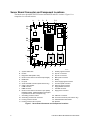
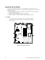
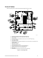
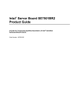
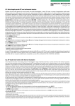
Server Board Connector and Component Locations
The Intel® server board SE7501WV2 comes in both SCSI and ATA versions. Figure 1 is a
composite view of both versions.
A
B
C
D
E
F G
DD
H
CC
I
J
K
BB
AA
Z
Y
X
W
V
U
S
T
R
Q
O
P
N
M
L
OM14124
A.
B.
C.
D.
E.
F.
G.
H.
I.
J.
K.
System status LED
ID LED
Diagnostic LEDs (POST code)
64-bit PCI riser slot for PCI-X bus B (full height)
DIMM slots
I/O ports
SCSI channel B connector (SCSI version only)
COM 1 serial header
ICMB connector
IPMB connector
64-bit PCI riser slot for PCI-X bus C (low profile)
RADIOS enabled. Modular ROM-B card support
is provided via the riser card (SCSI only)
L. Secondary processor socket
M. Secondary processor fan connector
N. Primary processor socket
O. Primary processor fan connector
P.
Q.
R.
S.
T.
U.
V.
W.
X.
Y.
Z.
Auxiliary signal connector
Sys fan 1 connector
Sys fan 2 connector
Main power connector
Battery
Power supply signal connector
ATX front panel connector
SSI front panel connector
Floppy/FP/IDE connector
ATA/IDE connector
Floppy drive connector
AA. USB 2 & 3 connector
BB. ATA-100 connectors (ATA version only)
CC. Hard Disk Drive LED header
DD. Speaker
Figure 1. Server Board Connector and Component Locations
2
Intel Server Board SE7501WV2 Product Guide
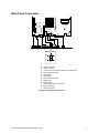
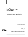
Back Panel Connectors
A
B
J
C
K
L
D
E
F
H
I
G
OM14125
A.
B.
C.
D.
E.
F.
G.
H.
I.
J.
K.
L.
USB 0 connector
Video connector
SCSI channel A connector (SCSI server board only)
NIC 2 RJ-45 connector
Status LED
Speed LED
NIC 1 RJ-45 connector
Status LED
Speed LED
PS/2 keyboard/mouse connector
RJ-45 serial port
USB 1 connector
Figure 2. Back Panel Connectors
Intel Server Board SE7501WV2 Product Guide
3
Processor
The SE7501WV2 accommodates one or two Intel® Xeon™ processors with 512k cache in the
INT3/FCPGA Socket 604 package. This processor uses the .13 micron technology. Check the
Intel Customer Support website for the latest list of supported processors see:
http://support.intel.com/support/motherboards/server/SE7501WV2
Memory
The system board has six 168-pin DIMM slots each supporting 72-bit ECC registered DDR
DIMMs (DDR200 or DDR266 compatible). Memory is partitioned in three banks. You may
install a minimum of 256 MB (128 MB x 2) and as much as 12 GB. Memory must be installed in
pairs, starting with bank 1 (slots 1B and 1A).
The controller automatically detects, sizes, and initializes the memory array, depending on the type,
size, and speed of the installed DIMMs, and reports memory size and allocation to the server via
configuration registers.
✏
NOTE
Use DIMMs that have been tested for compatibility with the server board.
Contact your sales representative or dealer for a current list of approved
memory modules. Check the Intel Customer Support website for the latest
tested memory list.
http://support.intel.com/support/motherboards/server/SE7501WV2
PCI Riser Slots
The server board has two PCI riser slots. Riser slot B provides the following features:
• 184 pin, 5 volt keyed, 64-bit expansion slot connector
• Support for either a 1-slot or a 3-slot PCI riser card
• Support for both full length and low profile PCI cards
Riser C provides the following features:
• 184 pin, 5 volt keyed, 64-bit expansion slot connector
• Support for either a 1-slot or a 3-slot PCI riser card
• Support for only low profile PCI cards
• RADIOS Enabled for use with zero channel RAID cards (SCSI version only)
Video
The SE7501WV2 uses an ATI RAGE XL PCI graphics accelerator with 8 MB of video SDRAM.
The embedded SVGA video subsystem supports:
• Resolutions up to 1600 x 1200 under 2D and 1024 x 768 under 3D
• CRT and LCD monitors up to 100 Hz vertical refresh rate
4
Intel Server Board SE7501WV2 Product Guide
The server board supports disabling of the onboard video through the BIOS setup menu or when a
plug in video card is installed in any of the PCI slots.
SCSI Controller
The SCSI version of the server board includes an embedded Adaptec† AIC-7902W controller
providing dual Ultra320 Low Voltage Differential (LVD) SCSI channels.
The SCSI bus is terminated on the server board with active terminators that cannot be disabled.
The onboard device must always be at one end of the bus. The device at the other end of the cable
must also be terminated. LVD devices generally do not have termination built-in and need to have
a termination source provided. Non-LVDs devices generally are terminated through a jumper or
resistor pack on the device itself.
ATA-100 Controller
The ATA version of the server board provides an embedded dual channel ATA-100 bus through the
use of the Promise Technology† PDC20277 ATA-100 controller. The controller contains two
independent ATA-100 channels that share a single 32-bit, 33-MHz PCI bus master interface as a
multifunction device. The controller supports:
• DMA and PIO IDE drives and ATAPI devices
• ATA and ATAPI proposal PIO Mode 0, 1, 2, 3, 4; DMA Mode 0, 1, 2; and Ultra DMA Mode
0, 1, 2, 3, 4, 5
• IDE transfer rates up to 100 MB/sec per channel
• Host interface complies with PCI Local Bus Specification Revision 2.2
IDE RAID
The ATA-100 controller supports IDE RAID through both ATA-100 channels. In a RAID
configuration, multiple IDE hard drives are placed into one or more arrays of disks. Each array is
seen as an independent disk, though the array may include one, two, three, or four drives. The IDE
RAID can be configured as follows:
• RAID 0: Striping one to four drives
• RAID 1: Mirroring two drives
• RAID 1 +: Spare drive (three drives)
• RAID 0 +: One to four drives are required
RAID 0 configurations are used for high performance applications, as it doubles the sustained
transfer rate of its drives. RAID 1 configurations are primarily used for data protection. It creates
an identical drive backup to a secondary drive. Whenever a disk write is performed, the controller
sends data simultaneously to a second drive located on a different data channel. With 4 drives
attached to dual ATA-100 channels, two striped drive pairs can mirror each other (RAID 0+1) for
storage capacity and data redundancy.
Intel Server Board SE7501WV2 Product Guide
5
Network Controller
✏
NOTE
To ensure EMC product regulation compliance, the system must be used
with a shielded LAN cable.
The server board uses the Intel® Fast Ethernet Controller, 82546EB, and supports two
10Base-T/1000Base-TX network subsystems.
The 82546EB controller supports the following features:
• 32-bit PCI master interface
• Integrated IEEE 802.3 10Base-T, 100Base-TX and 1000Base-TX compatible PHY
• IEEE 820.3u auto-negotiation support
• Full duplex support at 10 Mbps, 100 Mbps, and 1000 Mbps operation
• Low power +3.3 V device
On the SE7501WV2, NIC 1 can be used as both a network interface and server management
interface.
NIC Connector and Status LEDs
The E82546 controller drives LEDs on the network interface connector that indicate link/activity on
the LAN and speed of operation. The green LED indicates network connection when on and
TX/RX activity when blinking. The speed LED indicates 1000 Mbps when amber, 100 Mbps when
green, and 10 Mbps when off.
Keyboard and Mouse
The keyboard/mouse controller is PS/2-compatible. If specified through the System Setup Utility
(SSU), the server may be locked automatically if there is no keyboard or mouse activity for a
predefined length of time. Once the inactivity (lockout) timer has expired, the keyboard and mouse
do not respond until the previously stored password is entered. A Y-cable can be used if both a
PS/2 mouse and keyboard are required at the same time.
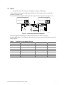
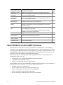
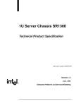
RJ-45 Serial Port
The rear RJ-45 serial port is a fully functional serial port that supports any standard serial device
and provides support for serial concentrators. For server applications that use a serial concentrator
to access the server management features of the baseboard, a standard 8-pin CAT-5 cable from the
serial concentrator is plugged directly into the rear RJ-45 serial port. The 8 pins of the RJ-45
connector can be configured to match either of two pin-out standards used by serial port devices.
To accommodate either standard, the J5A2 jumper block located directly behind the rear RJ-45
serial port must be jumpered appropriately according to the desired standard.
6
Intel Server Board SE7501WV2 Product Guide
✏
NOTE
By default, the RJ-45 serial port is configured to support a DSR signal.
For serial devices that require a DSR signal (default), the J5A2 jumper must be configured in
position 3-4 (Figure 3, B).
For serial devices that require a DCD signal, the jumper must be in position 1-2 (Figure 3, A).
A
B
5
5
DCD-DTR to Pin #7
DSR-DTR to Pin #7
C
6
2
6
2
OM14126
Figure 3. J5A2 Jumper Block for DSR Signal
For server applications that require a DB9 serial connector, you must use an 8-pin
RJ-45-to-DB9 adapter. The following table defines the pin-out required for the adapters to provide
RS232 support.
Table 3.
Rear Serial 2 Port Adapter Pin-out
RJ-45
Signal
Abbreviation
DB9
1
Request to Send
RTS
7
2
Data Terminal Ready
DTR
4
3
Transmitted Data
TD
3
4
Signal Ground
SGND
5
5
Ring Indicator
RI
9
6
Received Data
RD
2
7
DCD or DSR
DCD/DSR
1 or 6
8
Clear To Send
CTS
8
Intel Server Board SE7501WV2 Product Guide
7
ACPI
The SE7501WV2 supports the Advanced Configuration and Power Interface (ACPI) as defined by
the ACPI 2.0 specification. An ACPI aware operating system can put the system into a state where
the hard drives spin down, the system fans stop, and all processing is halted. However, the power
supply will still be on and the processors will still be dissipating some power, so the power supply
fans will still run.
The SE7501WV2 supports sleep states s0, s1, s4, and s5:
• s0: Normal running state.
• s1: Processor sleep state. No context will be lost in this state and the processor caches will
maintain coherency.
• s4: Hibernate or Save to Disk: The memory and machine state are saved to disk. Pressing the
power button or other wakeup event will restore the system state from the disk and resume
normal operation. This assumes that no hardware changes have been made to the system while
it was off.
• s5: Soft off: Only the RTC section of the CSB and the BMC are running in this state. No
context is saved by the OS or hardware.
CAUTION
The system is off only when the AC power cord is disconnected.
System Management
Intel integrates system management features into the hardware and provides additional features
through Intel® Server Management software. For instructions on using the features described
below, refer to the Configuration Software and Utilities chapter, beginning on page 39.
Baseboard Management Controller
Intel server boards incorporate a baseboard management controller (BMC), which is a dedicated
microcontroller for system management activities. The BMC performs the following functions:
•
•
•
•
8
Monitors system components and sensors, including processors, memory, fans, power supplies,
temperature sensors, and chassis intrusion sensors.
Manages nonvolatile storage for the system event log (SEL), sensor data records (SDRs), and
baseboard field-replaceable unit (FRU) inventory.
Interfaces with the emergency management port (EMP) and LAN1 port to send alerts and
interact with remote management systems.
Provides the main front panel control functions (power on/off, reset, and so on).
Intel Server Board SE7501WV2 Product Guide
Field Replaceable Units and Sensor Data Records
Field replaceable units (FRUs) are major modules in the chassis that contain active electronic
circuitry. FRUs can store information-such as board serial number, part number, name, and asset
tag-that can be read using the System Setup Utility. The BMC stores FRU information for the
baseboard in a nonvolatile storage component on the board.
The BMC uses Sensor Data Records (SDRs) to identify the sensors in the system for monitoring.
SDRs provide a list of the sensors, their characteristics, location, type, and type-specific
information, such as default threshold values, factors for converting a sensor reading into the
appropriate units (mV, rpm, degrees Celsius), and information on the types of events that a sensor
can generate. The BMC stores SDR information in a nonvolatile storage component on the
baseboard.
You can use the FRU/SDR Load Utility to initialize or update the FRU and SDR information. Intel
server boards are shipped from the factory with some sensors disabled because the actual
configuration of the chassis is only determined when the user completes the system configuration.
For example, chassis-specific FRU information, such as chassis part number, must be configured
when the system is configured. For these reasons, it is important to run the FRU/SDR Load Utility
as part of the system setup process. You should also run the FRU/SDR Load Utility whenever you
change the number of fans, processors, or power supplies in the server.
System Event Log
The BMC manages a system event log (SEL), where it records significant or critical system events.
These events include temperatures and voltages out of range, fan failures, and other sensor-related
events. The BIOS, software, and other devices can also log events by sending messages to the
BMC. The SEL is stored in nonvolatile storage.
You can view the current contents of the SEL by using the System Setup Utility.
Platform Event Management
Events can trigger alerts and other actions by the BMC. The server is configured with the
following set of standard events:
• Temperature sensor out of range
• Voltage sensor out of range
• Fan failure
• Chassis intrusion
• Power supply failure
• Memory error
• POST error
• Processor fault resilient booting (FRB) failure
• Fatal nonmaskable interrupt (NMI) from a source other than the front panel switch
• Watchdog timer reset, power down, or power cycle
• System restart (reboot)
Intel Server Board SE7501WV2 Product Guide
9
Alerts can take either of these forms:
• Platform Event Pages -- the BMC dials a paging service and sends a predefined paging string.
To use platform event paging (PEP), you must attach an external modem to the emergency
management port (Serial B).
• BMC LAN alerts -- the BMC sends an alert to a predefined destination on the LAN.
You can configure PEP and BMC LAN alerts by using the Server Configuration Wizard or the
System Setup Utility.
Emergency Management Port
The emergency management port (EMP) refers to the use of the Serial 2 port, with either an
external modem or direct serial connection, for remote management. The BMC controls the port
and interfaces with remote access software, such as the Direct Platform Control or the Client
System Setup Utility applications in Intel Server Management.
You can configure the EMP by using the Server Configuration Wizard or the System Setup Utility.
EMP and Serial Over LAN
The Serial B port 10-pin header on the board can be configured in several different ways: as a
standard serial port, as an Emergency Management Port, or for serial output redirection over a
LAN. You can configure these settings using either the SSU or the SCW.
✏
NOTES
Important Intel® Server Chassis SR1300 considerations: If you have
configured the Serial 2 port for use as an Emergency Management Port and
“always available”, the Serial 2 port will be accessible only by remote server
management software. The operating system will never be able to access
the port.
If you have configured the Serial 2 port for Serial Over LAN, the port’s
functionality will only be impacted when there is an active Serial Over LAN
session from a remote console. At all other times either the operating system
or EMP will control the port, depending on your configuration.
Intel® Server Management
Intel Server Management (ISM) is a system management package that is included on the ISM CD.
ISM applications interact with the integrated hardware system management features of the server to
allow you to monitor and manage a server from a remote workstation:
• Remote connection from a Windows†-based client workstation over a LAN, or over a modem
or direct serial connection to the emergency management port on the server.
• Real-time monitoring and alerting for server hardware sensors.
• Emergency management when the server is off (but still connected to AC power) lets you
verify the state of the server, diagnose hardware problems, and power on/off or reset the server.
• Ability to Run the Client System Setup Utility to change the configuration of the managed
server.
10
Intel Server Board SE7501WV2 Product Guide
ISM can use an optional service partition on the server that you are managing. The service partition
is a special disk partition on the system drive that contains a ROM-DOS† operating system and
DOS-based utilities, including the System Setup Utility, FRU/SDR Load Utility, and Remote
Diagnostics. The server can be booted to the service partition, either locally or remotely, to provide
access to the utilities.
For more information on Intel Server Management and the individual ISM applications, see the
ISM CD.
Security
Intrusion Switch Monitoring
To help prevent unauthorized entry or use of the server, Intel Server Management server
management software monitors the chassis intrusion switch if one is installed. Opening an access
cover will transmit an alarm signal to the server board, where BMC firmware and server
management software process the signal. The system can be configured through ISM to respond to
an intrusion a number of ways, including powering down or locking the keyboard.
Software Locks
The BIOS Setup and the System Setup Utility (SSU) provide a number of security features to
prevent unauthorized or accidental access to the system. Once the security measures are enabled,
you can access the system only after you enter the correct password(s). For example:
• Enable the keyboard lockout timer so that the server requires a password to reactivate the
keyboard and mouse after a specified time out period¾1 to 120 minutes.
• Set and enable a supervisor password.
• Set and enable a user password.
• Set secure mode to prevent keyboard or mouse input and to prevent use of the front panel reset
and power switches.
• Activate a hot key combination to enter secure mode quickly.
• Disable writing to the diskette drive when secure mode is set.
• Disable access to the boot sector of the operating system hard disk drive.
Using Passwords
You can set either the user password, the supervisor password, or both passwords. If only the user
password is set, you:
• Must enter the user password to enter BIOS Setup or the SSU.
• Must enter the user password to boot the server if Password on Boot is enabled in either the
BIOS Setup or SSU.
• Must enter the user password to exit secure mode.
Intel Server Board SE7501WV2 Product Guide
11
If only the supervisor password is set, you:
• Must enter the supervisor password to enter BIOS Setup or the SSU.
• Must enter the supervisor password to boot the server if Password on Boot is enabled in either
the BIOS Setup or SSU.
• Must enter the supervisor password to exit secure mode.
If both passwords are set, you:
• May enter the user password to enter BIOS Setup or the SSU. However, you will not be able to
change many of the options.
• Must enter the supervisor password if you want to enter BIOS Setup or the SSU and have
access to all of the options.
• May enter either password to boot the server if Password on Boot is enabled in either the BIOS
Setup or SSU.
• May enter either password to exit secure mode.
Secure Mode
Configure and enable the secure boot mode by using the SSU. When secure mode is in effect:
• You can boot the server and the operating system will run, but you must enter the user
password to use the keyboard or mouse.
• You cannot turn off system power or reset the server from the front panel switches.
Secure mode has no effect on functions enabled via remote server management or power control
via the watchdog timer.
Taking the server out of secure mode does not change the state of system power. That is, if you
press and release the power switch while secure mode is in effect, the system will not be powered
off when secure mode is later removed. However, if the front panel power switch remains
depressed when secure mode is removed, the server will be powered off.
12
Intel Server Board SE7501WV2 Product Guide
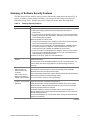
Summary of Software Security Features
The table below lists the software security features and describes what protection each offers. In
general, to enable or set the features listed here, you must run the SSU and go to the Security
Subsystem Group, menu. The table also refers to other SSU menus and to the Setup utility.
Table 4.
Software Security Features
Feature
Description
Secure mode
How to enter secure mode:
• Setting and enabling passwords automatically places the system in
secure mode.
• If you set a hot-key combination (through Setup), you can secure the system
simply by pressing the key combination. This means you do not have to wait
for the inactivity time-out period.
When the system is in secure mode:
• The server can boot and run the operating system, but mouse and keyboard
input is not accepted until the user password is entered.
• At boot time, if a CD is detected in the CD-ROM drive or a diskette in drive A,
the system prompts for a password. When the password is entered, the
server boots from CD or diskette and disables the secure mode.
• If there is no CD in the CD-ROM drive or diskette in drive A, the server boots
from drive C and automatically goes into secure mode. All enabled secure
mode features go into effect at boot time.
To leave secure mode: Enter the correct password(s).
Disable writing to
diskette
In secure mode, the server will not boot from or write to a diskette unless a
password is entered.
To write protect access to diskette whether the server is in secure mode or not,
use the Setup main menu, Floppy Options, and specify Floppy Access as
read only.
Set a time out period so
that keyboard and
mouse input are not
accepted
Also, screen can be
blanked, and writes to
diskette can be inhibited
Control access to using
the SSU: set supervisor
password
Specify and enable an inactivity time out period of from 1 to 120 minutes.
If no keyboard or mouse action occurs for the specified period, attempted
keyboard and mouse input will not be accepted.
The monitor display will go blank, and the diskette drive will be write protected (if
these security features are enabled through Setup).
To resume activity: Enter the correct password(s).
To control access to setting or changing the system configuration, set a
supervisor password and enable it through Setup.
If both the supervisor and user passwords are enabled, either can be used to
boot the server or enable the keyboard and/or mouse, but only the supervisor
password will allow Setup to be changed.
To disable a password, change it to a blank entry or press CTRL-D in the
Change Password menu of the Supervisor Password Option menu found in the
Security Subsystem Group.
To clear the password if you cannot access Setup, change the Clear Password
jumper (see Chapter 6).
continued
Intel Server Board SE7501WV2 Product Guide
13
Table 4.
Software Security Features (continued)
Feature
Description
Control access to the
system other than SSU:
set user password
To control access to using the system, set a user password and enable it
through Setup.
To disable a password, change it to a blank entry or press CTRL-D in the
Change Password menu of the User Password Option menu found in the
Security Subsystem Group.
To clear the password if you cannot access Setup, change the Clear Password
jumper (see Chapter 6).
14
Boot without keyboard
The system can boot with or without a keyboard. During POST, before the
system completes the boot sequence, the BIOS automatically detects and tests
the keyboard if it is present and displays a message.
Specify the boot
sequence
The sequence that you specify in setup will determine the boot order. If secure
mode is enabled (a user password is set), then you will be prompted for a
password before the server fully boots. If secure mode is enabled and the
“Secure Boot Mode” option is also enabled, the server will fully boot but will
require a password before accepting any keyboard or mouse input.
Intel Server Board SE7501WV2 Product Guide
2 Server Board Installations and Upgrades
Tools and Supplies Needed
•
•
•
•
Jumper removal tool or needle nosed pliers
Phillips† (cross head) screwdriver (#1 bit and #2 bit)
Pen or pencil
Antistatic wrist strap and conductive foam pad (recommended)
Cautions
These warnings and cautions apply throughout this chapter. Only a technically qualified person
should configure the server board.
CAUTIONS
System power on/off: The power button DOES NOT completely turn off
the system AC power, 5 V standby is still active whenever the system is
plugged in. To remove power from system, you must unplug the AC power
cord from the wall outlet. Make sure the AC power cord is unplugged before
you open the chassis, add, or remove any components.
Hazardous conditions, devices & cables: Hazardous electrical conditions
may be present on power, telephone, and communication cables. Turn off
the server and disconnect the power cord, telecommunications systems,
networks, and modems attached to the server before opening it. Otherwise,
personal injury or equipment damage can result.
Electrostatic discharge (ESD) & ESD protection: ESD can damage disk
drives, boards, and other parts. We recommend that you perform all
procedures in this chapter only at an ESD workstation. If one is not
available, provide some ESD protection by wearing an antistatic wrist strap
attached to chassis ground, (any unpainted metal surface), on your server
when handling parts.
ESD and handling boards: Always handle boards carefully. They can be
extremely sensitive to ESD. Hold boards only by their edges. After
removing a board from its protective wrapper or from the server, place the
board component side up on a grounded, static free surface. Use a
conductive foam pad if available but not the board wrapper. Do not slide
board over any surface.
Intel Server Board SE7501WV2 Product Guide
15
Installing or removing jumpers: A jumper is a small plastic encased
conductor that slips over two jumper pins. Some jumpers have a small tab on
top that you can grip with your fingertips or with a pair of fine needle nosed
pliers. If your jumpers do not have such a tab, take care when using needle
nosed pliers to remove or install a jumper; grip the narrow sides of the
jumper with the pliers, never the wide sides. Gripping the wide sides can
damage the contacts inside the jumper, causing intermittent problems with
the function controlled by that jumper. Take care to grip with, but not
squeeze, the pliers or other tool you use to remove a jumper, or you may
bend or break the stake pins on the board.
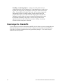
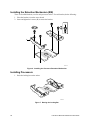
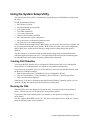
Rearrange the Standoffs
If your chassis does not have board mount standoffs placed as shown, you must rearrange them so
they match the holes in the server board. Failure to properly rearrange the metal standoffs may
cause the server board to malfunction and may permanently damage it. Your chassis may be
different from the illustration.
16
Intel Server Board SE7501WV2 Product Guide
=
OM14129
Figure 4. Rearrange the Standoffs
Intel Server Board SE7501WV2 Product Guide
17
Install the Server Board
To ensure proper grounding and support, it is recommended that you install screws in all the
required mounting holes for your chassis. You may need to move cables out of the way to properly
install your server board.
1. While placing the board on the chassis standoffs, carefully position the board I/O connectors
into the rear chassis I/O openings.
2. Adjust board position to align mounting holes with standoffs.
3. Using the screws that came with your chassis, mount the board to the chassis.
✏
NOTE
If you install the server board into Intel server chassis SR1300 or SR2300,
you will not use all of the mounting holes. See your chassis documentation
for more details.
OM14131
Figure 5. Installing the Server Board
18
Intel Server Board SE7501WV2 Product Guide
Installing or Replacing Processor(s)
WARNING
If the server has been running, any installed processor and heat sink on
the processor board(s) will be hot. To avoid the possibility of a burn, be
careful when removing or installing server board components that are
located near processors.
CAUTION
Processor must be appropriate: You may damage the server if you install
a processor that is inappropriate for your server. Make sure your server can
handle a newer, faster processor (thermal and power considerations). If you
are adding a second processor to your system, the second processor must be
compatible with the first processor (within one stepping, same voltage, same
speed). For exact information about processor interchangeability, contact
your customer service representative or visit the Intel Customer Support
website:
http://support.intel.com/
ESD and handling processors: Reduce the risk of electrostatic discharge
(ESD) damage to the processor by doing the following: (1) Touch the metal
chassis before touching the processor or server board. Keep part of your
body in contact with the metal chassis to dissipate the static charge while
handling the processor. (2) Avoid moving around unnecessarily.
Retention Mechanism (RM): In 2U and greater chassis, use the RM
brackets that ship with the chassis. Do not use the RM that shipped with the
processor.
Intel Server Board SE7501WV2 Product Guide
19
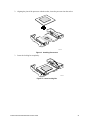
Installing the Retention Mechanism (RM)
There are four RM brackets, two for each processor socket. For each bracket, do the following:
1. Place the bracket (A) on the server board.
2. Insert and tighten two screws (B) to secure the bracket.
B
A
OM14144
Figure 6. Installing the Processor Retention Mechanism
Installing Processors
1. Raise the locking bar on the socket.
OM14132
Figure 7. Raising the Locking Bar
20
Intel Server Board SE7501WV2 Product Guide
2. Aligning the pins of the processor with the socket, insert the processor into the socket.
OM14133
Figure 8. Installing Processors
3. Lower the locking bar completely.
OM14135
Figure 9. Lower Locking Bar
Intel Server Board SE7501WV2 Product Guide
21
4. Follow the instructions packaged with your boxed processor for preparing the heat sink and
processor for installation.
5. Position the heat sink above the processor.
6. Aligning the raised metal surfaces, place the heat sink on top of the processor.
OM14134
Figure 10. Installing the Heat Sink
7. Place the heat sink clip (1) so the tab on the clip engages the slot on the heat sink (A).
8. Press one end of the clip down (2).
9. Press the other end of the clip down (3).
22
Intel Server Board SE7501WV2 Product Guide
OM14134
Figure 11. Installing the Heat Sink Clip
Replacing a Processor
1. Observe the safety and ESD precautions at the beginning of this chapter and the additional
cautions given here.
2. Disengage the retention clip from the processor socket.
3. Raise the locking bar on the socket. Refer to Figure 7.
4. Remove the processor from the socket.
5. Aligning the pins of the replacement processor with the socket, insert the processor into the
socket. Refer to Figure 8.
6. Lower the locking bar completely. Refer to Figure 9.
7. Follow the instructions packaged with your boxed processor for preparing the heat sink and
processor for installation.
8. Position the heat sink above the processor. Refer to Figure 10.
9. Aligning the raised metal surfaces, place the heat sink on top of the processor.
10. Place the heat sink clip (1) so the tab on the clip engages the slot on the heat sink (A).
11. Press one end of the clip down (2).
12. Press the other end of the clip down (3).
Intel Server Board SE7501WV2 Product Guide
23
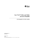
Memory
Only DDR200 or DDR266 compliant SDRAM is supported by the server board. Install from
256 MB to 12 GB of registered, ECC memory, using up to six DIMMs. A 1U chassis requires
low-profile (LP) 1.2-inch DIMMs.
✏
NOTE
Only DDR266 is supported with a 533 MHz Front Side Bus.
DIMMs must be installed in pairs and in the following order: 1B and 1A, 2B and 2A, 3B and 3A.
Installed DIMMs must be the same speed and must all be registered. For a list of supported
memory, call your service representative or visit the Intel Support website:
http://support.intel.com/support/motherboards/server/SE7501WV2
1B 2B 3B
1A 2A 3A
OM14138
Figure 12. Installing Memory
24
Intel Server Board SE7501WV2 Product Guide
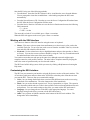
Connect Cables
Before connecting cables, consult the documentation supplied with your chassis.
A
C
O
M
1
O
A
T
A
1
0
0
B
N
M
C
S
C
S
I
U
S
B
A
T
A
6
6
D
L
E
F
K
J
I
H
G
OM14139
A.
B.
C.
D.
E.
F.
G.
H.
I.
J.
K.
L.
M.
N.
O.
External SCSI channel A connector (SCSI server board only)
Internal SCSI channel B connector (SCSI server board only)
Serial 1 header
Combined Floppy/Front Panel/IDE connector (For use in an Intel® chassis only)
Fan module connector
Fan module connector
Processor fan connectors (May be required for use in non Intel chassis. Not required for use
with Intel chassis)
Auxiliary power connector
Main power connector
Power supply signal connector
Front panel connector (For use in a non Intel chassis only)
Floppy connector (For use in a non Intel chassis only)
IDE connector (For use in a non Intel chassis only)
USB header
ATA-100 primary/secondary connectors (ATA server board only)
Figure 13. Connecting Cables
Intel Server Board SE7501WV2 Product Guide
25
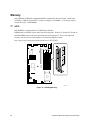
Replacing the Back up Battery
The lithium battery on the server board powers the real time clock (RTC) in the absence of AC
power. When the battery starts to weaken, it loses voltage, and the server settings stored in CMOS
RAM in the RTC (for example, the date and time) may be wrong. Contact your customer service
representative or dealer for a list of approved devices.
WARNING
Danger of explosion if battery is incorrectly replaced. Replace only with
the same or equivalent type recommended by the equipment
manufacturer. Discard used batteries according to manufacturer’s
instructions.
ADVARSEL!
Lithiumbatteri - Eksplosionsfare ved fejlagtig håndtering. Udskiftning
må kun ske med batteri af samme fabrikat og type. Levér det brugte
batteri tilbage til leverandøren.
ADVARSEL
Lithiumbatteri - Eksplosjonsfare. Ved utskifting benyttes kun batteri
som anbefalt av apparatfabrikanten. Brukt batteri returneres
apparatleverandøren.
VARNING
Explosionsfara vid felaktigt batteribyte. Använd samma batterityp eller
en ekvivalent typ som rekommenderas av apparattillverkaren. Kassera
använt batteri enligt fabrikantens instruktion.
VAROITUS
Paristo voi räjähtää, jos se on virheellisesti asennettu. Vaihda paristo
ainoastaan laitevalmistajan suosittelemaan tyyppiin. Hävitä käytetty
paristo valmistajan ohjeiden mukaisesti.
26
Intel Server Board SE7501WV2 Product Guide
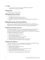
To replace the battery:
1. Before proceeding, record your custom BIOS settings.
2. Observe the safety and ESD precautions at the beginning of this chapter.
3. Open the chassis and locate the battery.
4. Push the upper end of the metal retainer away from the battery-the battery pops up.
5. Remove the battery from its socket.
6. Dispose of the battery according to local ordinance.
7. Remove the new lithium battery from its package.
8. Being careful to observe the correct polarity, lay the battery in the socket.
9. Push the battery down-the metal retainer locks the battery in the socket.
10. Close the chassis.
11. Run Setup to restore the configuration settings to the RTC.
12. Restore your custom BIOS settings.
OM14141
Figure 14. Replacing the Back up Battery
Intel Server Board SE7501WV2 Product Guide
27
28
Intel Server Board SE7501WV2 Product Guide
3 POST and BIOS Setup Utilities
This chapter describes the POST and BIOS setup utilities provided with the SE7501WV2 server. It
includes information about the Adaptec SCSI Utility and the Promise FastBuild† Utility. For
information about server management utilities, see Chapter 4 on page 39.
Table 5.
POST and BIOS Setup Utilities
Utility
Description and brief procedure
Page
Changing boot priority
through POST
Change the boot device for the current boot.
30
Adaptec SCSI Utility
Use to view / configure the settings for the Adaptec AIC-7902 SCSI
host adapter
29
Promise FastBuild
Utility
Use with ATA systems to view / configure the RAID settings
32
BIOS Setup
Use to configure system options
32
BIOS Update Utility
Use to update the BIOS or recover from a corrupted BIOS update.
41
Hot Keys
Use the numeric pad of the keyboard to enter numbers and symbols.
Table 6.
Hot Keys
To Do This:
Press These Keys
Secure your system immediately.
<Ctrl+Alt>+hot key (Set your hot key combination with
the SSU or BIOS Setup)
Enter the Adaptec SCSI Utility during POST.
<Ctrl+A> (SCSI version only)
Enter the Promise Technology IDE RAID Utility.
<Ctrl+F> (ATA version only)
Enter BIOS Setup during POST.
<F2>
Abort memory test during POST.
<ESC> (Press while BIOS is updating memory size on
screen)
Display a menu for selecting the boot device.
<ESC> (Press anytime after memory check)
To remove the splash screen.
<ESC>
Power-On Self-Test (POST)
Each time you turn on the system, the BIOS begins executing the Power-On Self-Test (POST),
which is stored in flash memory. POST discovers, configures, and tests the processors, memory,
keyboard, and most installed peripheral devices. During the memory test, POST displays the
amount of memory that it is able to access and test. The time needed to test memory depends on
the amount of memory installed.
1. Turn on your server and monitor. After a few seconds, POST begins to run and displays a
splash screen.
2. While the splash screen is displayed, make one of the following selections:
• Press <F2> to enter the BIOS Setup.
Intel Server Board SE7501WV2 Product Guide
29
•
Press <Ctrl-A> to enter the Adaptec SCSISelect† Utility. See page 30 for information
about the Adaptec SCSISelect Utility.
• Press <Ctrl-F> to enter the Promise FastBuild Utility. See page 32 for information about
the Promise FastBuild Utility.
• Press <Esc> to view POST diagnostic messages and change the boot device priority for this
boot only.
3. If you do not make one of the above selections and do NOT have a device with an operating
system loaded, the boot process continues and the system beeps once. The following message
is displayed:
Operating System not found
What appears on the screen after this depends on whether you have an operating system loaded and
if so, which one.
If the system halts before POST completes running, it emits a beep code indicating a fatal system
error that requires immediate attention. If POST can display a message on the video display screen,
it causes the speaker to beep twice as the message appears.
Write down both the screen display and the beep code you hear; this information is useful for your
service representative. For a listing of common beep codes and error messages that POST can
generate, see the “Solving Problems” chapter in this manual.
Temporarily Changing the Boot Device Priority
During POST, you can change the boot device priority for the current boot process. The changes
are not saved for the next boot process.
1. Boot the server.
2. At any time during POST, press <Esc>. When POST completes, a popup Boot menu displays.
3. Use the arrow keys to highlight the device you want the server system to boot from first. For
example, if you want the server system to boot from the CD-ROM first, you select “ATAPI
CD-ROM Drive.”
✏
NOTE
If you boot to a CD-ROM, make sure the CD is in the CD drive before
selecting. One of the options on the popup Boot menu is “Enter Setup.”
Selecting this option brings you into the BIOS Setup.
4. Press <Enter> and the boot process continues.
The Adaptec SCSISelect Utility
Each host adapter includes an onboard SCSISelect configuration utility that allows you to
configure/view the settings of the host adapter and devices in the server.
The system finds the Adaptec AIC-7902 SCSI host adapter and displays the message Adaptec
AIC-7902 SCSI BIOS V x.xxx where x.xxx is the version number of the SCSISelect utility.
Pressing <Ctrl+A> at this time allows you to configure the Adaptec AIC-7902 SCSI host adapter.
30
Intel Server Board SE7501WV2 Product Guide
When to Run the Adaptec SCSISelect Utility
Use the SCSISelect utility to:
• Change default values
• Check and/or change SCSI device settings that may conflict with those of other devices in the
server
• Do a low-level format on SCSI devices installed in the server
Running the SCSISelect Utility
1. When this message appears on the video monitor:
<<<Press <Ctrl><A> for SCSISelect(TM) Utility!>>>
2. Press <Ctrl+A> to run the utility. When the main menu for the host adapter appears, choose
the device that you want to configure-each SCSI bus accepts up to 15 devices.
Use the following keys to navigate through the menus and submenus:
Table 7.
Press
SCSISelect Navigation Keys
To
ESC
Exit the utility
Enter
Select an option
↑
Return to a previous option
↓
Move to the next option
F5
Switch between color and monochrome
F6
Reset to host adapter defaults
Configuring the Adaptec AIC-7902 SCSI Adapter
The Adaptec AIC-7902 SCSI adapter has two busses. Select the bus from the following menu:
Table 8.
Adaptec Main Menu
Menu Item
Options
You have an AIC-7902 adapter in your system.
Move the cursor to the bus:device:channel of the
one for configuration and press <Enter>.
Bus:Device:Channel
01:06:A
01:06:B
<F5> - Toggle color/monochrome.
Intel Server Board SE7501WV2 Product Guide
31
After selecting the bus, the following menu displays:
Table 9.
Menu for each SCSI Channel
Host Adapter
Option
Comment
AIC-7902 at
Bus:Device:Channel
01:06:A (or 01:06:B)
Configure/View
Host Adapter
Settings
Press <Enter> to view the Configuration Menu.
SCSI Disk Utilities
Press <Enter> to view the SCSI Disk Utilities Menu. This
menu allows you to format hard disks and/or verify disk
media.
When you are finished, press <Esc> and make your selection from the following menu:
Table 10.
Exit Menu
Feature
Option
Comment
Exit Utility?
Yes
No
When you finish configuring your SCSI devices, press <Esc>. Then select Yes
and press <Enter>. When this message appears:
Please press any key to reboot.
Press any key, and the server reboots.
The Promise FastBuild* Utility (SE7501WV2 ATA
Model Only)
This utility is only found on the SE7501WV2 ATA model only.
The Promise ATA-100 host adapter is configured using the FastBuild configuration utility that
allows you to configure/view the settings of the host adapter and set RAID configurations.
When to Run the Promise FastBuild Utility
Use the FastBuild utility to:
• Define a RAID array
• Delete a RAID array
• Restore a RAID array
Running the Promise FastBuild Utility
1. When this message appears on the video monitor:
<<<Press <Ctrl><F> to enter FastBuild (TM) Utility>>>
2. Press <Ctrl+F> to run the utility.
BIOS Setup
You can run BIOS Setup with or without an operating system being present. BIOS Setup stores
most of the configuration values in battery-backed CMOS; the rest of the values are stored in flash
memory. The values take effect when the system is booted. POST uses these values to configure
the hardware. If the values and the actual hardware do not agree, POST generates an error
message.
32
Intel Server Board SE7501WV2 Product Guide
Record your BIOS Setup settings. If default values ever need restoring (after a CMOS clear, for
example), you must run BIOS Setup again. Your record will make this much easier.
If BIOS Setup Is Inaccessible
If you are not able to access BIOS Setup, you might need to clear the CMOS memory. To clear
CMOS, either of two methods can be used:
•
•
Press the reset button and hold it down for four seconds or more, and then, while holding the
reset button down, press the power button. Release both buttons at the same time
OR
Move the Clear CMOS jumper found on the configuration jumper block on the baseboard.
Starting Setup
You can enter and start Setup under several conditions:
• When you turn on the server, after POST completes the memory test
• When you have moved the CMOS jumper on the server board to the “Clear CMOS” position
(enabled). For instructions on moving the jumper, see Chapter 6, under the heading “Clearing
CMOS with the CMOS Jumper”
In these two conditions, after rebooting, you will see this prompt:
Press <F2> to enter SETUP
•
In a third condition, when CMOS/NVRAM has been corrupted, you will see other messages
but not the <F2> prompt:
Warning:
Warning:
CMOS checksum invalid
CMOS time and date not set
In this condition, the BIOS will load default values for CMOS and attempt to boot.
Setup Menus
Each Setup menu page contains a number of features. Except those used for information purposes,
each feature is associated with a value field that contains user-selectable parameters. Parameters
may be changed depending upon the security option chosen. If a value is not changeable due to
insufficient security privileges (or other reasons), the feature’s value field becomes inaccessible.
The bottom portion of the Setup screen provides a list of commands that are used for navigating the
Setup utility.
Intel Server Board SE7501WV2 Product Guide
33
Table 11.
Press
Keyboard Commands
Description
<F1>
Help - Pressing F1 on any menu invokes the general Help window.
←→
The left and right arrow keys are used to move between the major menu pages. The keys have
no affect if a submenu or pick list is displayed.
↑
Select Item up - The up arrow is used to select the previous value in a menu item’s option list, or
a value field pick list. Pressing the Enter key activates the selected item.
↓
Select Item down - The down arrow is used to select the next value in a menu item’s option list,
or a value field pick list. Pressing the Enter key activates the selected item.
F5/-
Change Value - The minus key or the F5 function key is used to change the value of the current
item to the previous value. This key scrolls through the values in the associated pick list without
displaying the full list.
F6/+
Change Value - The plus key or the F6 function key is used to change the value of the current
menu item to the next value. This key scrolls through the values in the associated pick list
without displaying the full list. On 106-key Japanese keyboards, the plus key has a different
scan code than the plus key on the other keyboard, but it has the same effect.
<Enter>
Execute Command - The Enter key is used to activate submenus when the selected feature is a
submenu, or to display a pick list if a selected feature has a value field, or to select a sub-field for
multi-valued features like time and date. If a pick list is displayed, the Enter key will undo the
pick list, and allow another selection in the parent menu.
<Esc>
Exit - The ESC key provides a mechanism for backing out of any field. This key will undo the
pressing of the Enter key. When the ESC key is pressed while editing any field or selecting
features of a menu, the parent menu is re-entered. When the ESC key is pressed in any
submenu, the parent menu is re-entered. When the ESC key is pressed in any major menu, the
exit confirmation window is displayed and the user is asked whether changes can be discarded.
<F9>
Setup Defaults - Pressing F9 causes the following to appear:
Setup Confirmation
Load default configuration now?
[Yes] [No]
If “Yes” is selected and the Enter key is pressed, all Setup fields are set to their default values. If
“No” is selected and the Enter key is pressed, or if the ESC key is pressed, the user is returned
to where they were before F9 was pressed without affecting any existing field values.
<F10>
Save and Exit - Pressing F10 causes the following message to appear:
Setup Confirmation
Save Configuration changes and exit now?
[Yes] [No]
If “Yes” is selected and the Enter key is pressed, all changes are saved and Setup is exited. If
“No” is selected and the Enter key is pressed, or the ESC key is pressed, the user is returned to
where they were before F10 was pressed without affecting any existing values.
Table 12.
On-Screen Options
When you see this:
What it means:
On screen, an option is shown but you
cannot select it or move to that field.
You cannot change or configure the option in that menu screen.
Either the option is auto-configured or auto-detected, or you must
use a different Setup screen.
Press <Enter> to display a submenu that is either a separate full
screen menu or a popup menu with one or more choices.
On screen, the phrase Press Enter
appears next to the option.
34
Intel Server Board SE7501WV2 Product Guide
Upgrading the BIOS
Preparing for the Upgrade
Before you upgrade the BIOS, prepare for the upgrade by recording the current BIOS settings and
obtain the upgrade utility.
Recording the Current BIOS Settings
1. Boot the computer and press <F2> when you see the message:
Press <F2> Key if you want to run SETUP
2. Write down the current settings in the BIOS Setup program.
✏
NOTE
Do not skip step 2 above. You will need these settings to configure your
computer at the end of the procedure.
Obtaining the Upgrade Utility
You can upgrade to a new version of the BIOS using the new BIOS files and the BIOS upgrade
utility, iFLASH.EXE. You can obtain the BIOS upgrade file and the iFLASH.EXE utility through
your computer supplier or from the Intel Customer Support website:
http://support.intel.com/support/motherboards/server/SE7501WV2
✏
NOTE
Review the instructions distributed with the upgrade utility before attempting
a BIOS upgrade.
This upgrade utility allows you to upgrade the BIOS in flash memory. The following steps explain
how to upgrade the BIOS.
Creating a Bootable Diskette
1. Use a DOS system to create the diskette.
2. Insert a diskette in diskette drive A.
3. At the C:\ prompt, for an unformatted diskette, type:
format a: /s
or, for a formatted diskette, type:
sys a:
4. Press <Enter>.
Intel Server Board SE7501WV2 Product Guide
35
Creating the BIOS Upgrade Diskette
The BIOS upgrade file is a compressed self-extracting archive that contains the files you need to
upgrade the BIOS.
1. Insert the bootable diskette into the diskette drive.
2. Extract the contents of the BIOS.EXE file onto the bootable diskette. To do this, type
BIOS.EXE A:
3. The BIOS upgrade image files are extracted directly into the floppy disk.
Performing the BIOS Upgrade
1. Place the bootable diskette containing the BIOS update files into the diskette drive of your
system. Boot the system with the diskette in the drive.
2. At this point you have a choice of two options. Press 1 and <Enter> to automatically update
the system BIOS. This will update the system BIOS and reset the system. Press 2 and <Enter>
to update the User Binary and reset the system.
3. Wait while the BIOS files are updated. Do not power down the system during the BIOS update
process! The system will reset automatically when the BIOS update process is completed.
Remove the diskette from the diskette drive.
4. Verify that the BIOS version displayed during POST is the new version as the system reboots.
5. Enter Setup by pressing the F2 key during boot. Once in Setup, press the F9 and <Enter> to set
the parameters back to default values.
6. Re-enter the values you wrote down at the beginning of this process. Press F10 and <Enter> to
exit BIOS Setup and Save Changes.
7. If you do not set the CMOS values back to defaults using the F9 key, the system may function
erratically.
✏
NOTE
You may encounter a CMOS Checksum error or other problem after reboot.
Try shutting down the system and booting up again. CMOS checksum errors
require that you enter Setup, check your settings, save your settings, and
exit Setup.
It is unlikely that anything will interrupt the BIOS upgrade; however, if an interruption occurs, the
BIOS could be damaged. See “Recovering the BIOS” in Chapter 5 for instructions on recovering
the BIOS.
36
Intel Server Board SE7501WV2 Product Guide
Changing the BIOS Language
You can use the BIOS upgrade utility to change the language that the BIOS uses for messages and
for the Setup program. Use a bootable diskette containing the Intel flash utility and language files.
1. Boot the computer with the bootable diskette in drive A. The BIOS upgrade utility screen
appears.
2. Select Update Flash Memory From a File.
3. Select Update Language Set. Press <Enter>.
4. Select drive A and use the arrow keys to select the correct .lng file. Press <Enter>.
5. When the utility asks for confirmation that you want to flash the new language into memory,
select Continue with Programming. Press <Enter>.
6. When the utility displays the message upgrade is complete, remove the diskette. Press
<Enter>.
7. The computer will reboot and the changes will take effect.
Intel Server Board SE7501WV2 Product Guide
37
38
Intel Server Board SE7501WV2 Product Guide
4 Configuration Software and Utilities
System Software Update Sequence
When you update the system software, you should do it in the following order.
1. Update firmware (BMC & HSC)
2. Update FRU/SDR
3. Unplug system for 30 seconds
4. Update BIOS
5. Clear CMOS
Server Configuration Wizard
The Server Configuration Wizard (SCW) is a utility that is provided to help you configure your
server. The Server Configuration Wizard is located on the System Resource CD-ROM shipped
with the server and it runs automatically when you boot your server to this CD-ROM. The Server
Configuration Wizard includes a help system that can be accessed by clicking the Help button.
Run the Configuration to:
• Create or update a Service Partition and install service partition files, including files that are
necessary to run the System Setup Utility
• Load FRUs and SDRs
• Set the System Asset Tag
• Set Server Management settings, including an IP address, emergency management port (EMP)
settings, platform event paging (PEP) settings, and LAN/Alert settings
• Execution utility applications that can be used to manually configure the server
• Create startup or installation diskettes for hardware device drivers and server configuration
utility applications
When it is first executed, the SCW probes the server for installed devices, firmware, chassis
information, hard disks, and other relevant data. This information is used to determine the
questions the application needs to ask you to complete the configuration.
When you select the options Server Configuration Wizard > Run Wizard, you will be shown a
selection window allowing you to choose the items you want to configure. You can select one or
more options to configure at the same time. Some options have dependencies that make you select
multiple options. These are:
• If you select Configure this server for LAN Alerting, the option for Configure this server for
remote Server Management over a LAN connection will automatically be selected.
• If you select Configure this server for Serial/Modem alerting, the option for Configure this
server for remote Server Management over a Serial/Modem connection will automatically be
selected.
In addition, you can select only one of the following at a time:
• Load SDRs only onto this server
OR
• Load FRUs and SDRs onto this server
If you select multiple options, the Server Configuration Wizard will run each option to completion.
Intel Server Board SE7501WV2 Product Guide
39
To use the Server
Configuration utility to
Description of procedure
Page
Configure the server for
remote LAN
management
Enable a connection to the server from a workstation on the LAN to
allow remote management functions, such as powering the server on or
off, or running diagnostic utilities.
48
Configure for Remote
Serial / Modem
management
Enable a connection to the server from a serial or Modem connection to
allow remote management functions, such as powering the server on or
off, or running diagnostic utilities.
49
Configure for Serial /
Modem alerting
Configure the server to send a telephone page in the event that a
hardware or firmware error occurs at the server.
51
Configure for LAN
alerting
Configure the server to send a notification message to a workstation
segment of the network in the event that a hardware or firmware error
occurs at the server.
52
Run the FRU/SDR Load
Utility
Use to update the Field Replaceable Unit (FRU) and Sensor Data
Record (SDR) flash components.
55
NOTE: You must run the FRU/SDR Load utility whenever the BMC is
updated or if you change your processors.
Configure an Asset Tag
Assign an identification number or serial number to the server.
58
Create / modify the
service partition
If a service partition does not already exist, create one. If a service
partition has been created earlier, update it.
59
Create System or Utility
/ Device Diskettes
Create diskettes by operating system, utility, or device driver.
58
Save / load
configuration data
Save the configuration data to a file. Use this saved file to configure
other servers identically.
60
Direct Platform Control (DPC) Console
Direct Platform Control (DPC) Console is part of Intel Server Management. Direct Platform
Control is a server management application that supports remote system management via LAN, or
an RS-232 serial connection to the server Serial B port over a modem or a direct serial cable. The
Direct Platform Control Console provides the ability for remote management of Intel servers via
modem or LAN with a capability to run DOS-based programs.
DPC console runs on a client workstation and is independent of the server operating system. It
communicates with a server by:
• Accessing the server management capabilities of the on-board NIC
• A Windows 2000 compatible modem
• An RS-232 connection to the server’s Serial B port
Even when the server is off, you can use DPC Console to verify the state of a server or diagnose a
problem with the server hardware. DPC console features allows you to:
• Establish connection to remote servers
• Server Control: power on, power off, and reset operations
• Retrieve and display entries in the System Event Log (SEL)
• Retrieve and display Sensor Data Records (SDR)
• Retrieve and display Field Replaceable Unit (FRU) information
40
Intel Server Board SE7501WV2 Product Guide
•
•
•
•
Retrieve and display current Remote Sensor Access (RSA) information
Access a phonebook for remote connection management
Remote control of the service partition
File transfer from / to the server
DPC Console Modes of Operation
There are four DPC console modes of operation:
• EMP mode. Access the DPC console features using the DPC console window menus and/or
toolbar. Active when a connection is established through the EMP port (Serial B).
•
•
•
DPC over LAN mode. Access the DPC console features using the DPC console window
menus and/or toolbar. Active when a connection is established through the LAN.
Re-direct mode. Active when the server is running BIOS console redirection. In this mode, the
DPC console launches a separate window. The window operates as an ANSI terminal and
communicates with the server through the port. Character-based commands you type in the
DPC Console go directly to the server, and the DPC Console displays the text that you would
normally see on the server console.
To use this mode, you must configure the Console Redirection option of BIOS Setup for
Re-direct mode. Enabling Console Redirection requires that the Boot Time Diagnostics Screen
be Enabled in BIOS Setup. If the redirection window does not display information, the
Console Redirection is either incorrectly configured or disabled, the EMP is disabled in BIOS
Setup, or the server is in protected mode. For DPC to function in this mode, the server must
NOT be in graphics mode.
If the DPC console fails to connect in EMP within 10 seconds and the server can operate in
Re-direct mode, a prompt is displayed with the option to switch to Re-direct mode.
Service Partition mode. Entered when the server reboots from the service partition and the
DPC Console has successfully connected to the server. This mode allows running of
DOS-based programs that are stored on the service partition and transferring of files.
Running the DPC Console
For more information about setting up and running the DPC Console, see the ISM Installation
User’s Guide. This document is in the ISM\DOCS\[language] directory on the ISM CD
accompanying the SE7501WV2 server board.
Intel Server Board SE7501WV2 Product Guide
41
Using the System Setup Utility
The System Setup Utility (SSU) is located on the System Resource CD-ROM that is shipped with
the server.
Run the System Setup Utility to:
• Set boot device priority
• Set passwords and security options
• View system events
• View FRU information
• View sensor data records
• Update system firmware and BIOS
• Save and restore the system configuration
• Set up the server to send alerts for platform events
• Set up the server for remote management
Using either the System Setup Utility or BIOS Setup, you can specify the boot device sequence and
set up system passwords and security options. Both utilities access the same stored configuration
data for these items, and the result of making a change to these settings using either utility is
identical.
The SSU consists of a collection of task-oriented modules plugged into a common framework
called the Application Framework (AF). The Application Framework provides a launching point
for individual tasks and a location for setting customization information.
Creating SSU Diskettes
You can run the SSU from the Server Configuration Utilities menu of the Server Configuration
Wizard, from a set of DOS diskettes, or from the service partition of the hard disk.
If you choose to run the SSU from a set of DOS diskettes, you must create the SSU diskettes from
the Resource CD-ROM as follows:
1. Boot the System Resource CD-ROM to the Server Configuration Wizard.
2. Choose Create Diskettes > Create Diskettes by Device/Function > System Setup Utility.
3. Follow the instructions displayed.
Alternatively, if you have a workstation with the Microsoft Windows† operating system, you can
insert the CD into that system and create the diskettes on that system.
Running the SSU
When the SSU starts in the default local execution mode, it accepts input from the keyboard or
mouse. The SSU presents a VGA-based GUI on the primary monitor.
If you run the SSU from read-only media you cannot save user preference settings (such as
screen colors).
The SSU supports ROM-DOS version 6.22. The SSU will not operate from a “DOS box” running
under an operating system such as Windows.
42
Intel Server Board SE7501WV2 Product Guide
Start the SSU using one of the following methods:
• From diskettes: Insert the first SSU diskette in drive A and boot the server from the diskette.
You are prompted to insert the second diskette. After loading completes the SSU starts
automatically.
• From the System Resource CD: Boot the server to the Server Configuration Wizard and start
the SSU from the Server Configuration Utilities menu.
• From the Service Partition: Boot the server to the Service Partition and execute the following
DOS commands:
C:\> cd ssu
C:\SSU> ssu.bat
The mouse driver loads if it is available; press <Enter> to continue.
When the SSU title appears on the screen, press <Enter> to continue.
Working with the SSU Interface
You can access features of the SSU interface using the mouse or keyboard:
• Mouse: Click once to choose menu items and buttons or to select items in a list, such as the
Available Tasks list. To run a list item, such as one of from the Available Tasks list, select the
item and click OK or double-click the item.
• Keyboard: Use the tab and arrow keys to highlight buttons and press the spacebar or <Enter>
to execute. You can also execute a menu or button by using the <Alt> key in combination with
the underlined letter in the name of the menu or button.
You can have more than one task open at the same time, although some tasks might require
complete control to avoid possible conflicts. The tasks achieve complete control by keeping the
task as the center of operation until you close the task window.
The SSU has a build-in help system, which you access by clicking a Help button or choosing the
Help menu.
Customizing the SSU Interface
The SSU lets you customize your interface using the Preferences section of the main window. The
AF sets these preferences and saves them in the AF.INI file so that they take effect the next time
you start the SSU. There are four user customizable settings:
• Color: lets you change the default colors associated with different items on the screen using
predefined color combinations. The color changes take effect immediately.
• Mode: lets you set the desired expertise level: novice, intermediate, or expert. The expertise
level determines which tasks are visible in the Available Tasks section and which actions each
task performs. For a new mode setting to take effect, you must exit the SSU and restart it.
• Language: lets you change the text in the SSU to the appropriate language. For a new
language setting to take effect, you must exit the SSU and restart it.
• Other: lets you show or hide the status bar at the bottom of the SSU main window. The
change takes effect immediately.
Intel Server Board SE7501WV2 Product Guide
43
✏
NOTE
If you run the SSU from read-only media (CD-ROM, for example), these
preferences are lost when you exit the SSU.
Exiting the SSU
Exiting the SSU closes all SSU windows.
Setting Boot Device Priority
To change the boot priority of a device:
1. From the SSU Main window, choose Boot Devices.
2. In the Multiboot Options Add-in window, select a device.
3. Click the Move Up button to move it up in the list. Click the Move Down button to move
it down.
Setting Passwords and Security Options
You can set a user password and an administrator password for the server. You must set an
administrator password before you can set a user password. On other systems, the passwords are
independent. You can set the same passwords and security options by using BIOS Setup.
Setting the Administrator Password
The Admin Password button lets you set or change the administrator password used by both the
SSU and the system BIOS. This option is not available if both an administrator and a user
password are set and you entered only the user password when you started the SSU. All changes to
the administrator password take effect immediately.
To change or clear the administrator password:
1. From the SSU Main window, choose Security.
2. Click the Admin Password button.
3. If you are changing passwords, enter the old password.
4. Enter the new password (or leave blank to clear).
5. Confirm the password by entering it again (or leave blank to clear).
6. Click OK to save the password and return to the Security window.
Setting the User Password
The User Password button lets you set or change the user password used by both the SSU and the
system BIOS. All changes to the user password take effect immediately.
To change or clear the user password:
1. From the SSU Main window, choose Security.
2. Click the User Password button.
3. If you are changing passwords, enter the old password in the first box.
4. Enter the new password (or leave blank to clear).
5. Confirm the password by entering it again (or leave blank to clear).
6. Click OK to save the password and return to the Security window.
44
Intel Server Board SE7501WV2 Product Guide
Setting Security Options
For a description of security features, see Table 4. Software Security Features.
To set the security options:
1. In the Security window, click the Options button.
2. For each option, select the desired setting from the list. The options are:
• Security Hot Key: The key combination that can be used to put the server into
secure mode.
• Secure Mode Timer: If no keyboard or mouse activity occurs during the chosen time
interval, the server enters secure mode.
• Secure Mode Boot: Enable forces the server to boot directly into secure mode.
• Video Blanking: Enable turns off the video when the server is in secure mode.
• Floppy Write: Enable prevents writing to the diskette drive while the server is in
secure mode.
• Power Switch Inhibit: Enable prevents the power and reset buttons from functioning
when the server is in secure mode. Disable allows the power and reset buttons to function
normally when the server is in secure mode.
3. Click Save to save the settings and return to the Security window.
Viewing the System Event Log
To view the System Event Log (SEL):
1. From the SSU Main window, choose SEL Manager.
When you start the SEL Manager, it automatically loads the current list of events from
non-volatile memory.
2. Use the <F4> and <F5> keys to scroll the window contents to the left and right to view all of
the columns.
3. Use the File and SEL menu items to work with the SEL information:
• Open: Views data from a previously saved SEL file.
• Save As: Saves the currently loaded SEL data to a file.
• Properties: Displays information about the SEL.
• Clear SEL: Clears the SEL data from the nonvolatile storage area.
• Reload: Refreshes the display by reading the current SEL entries from the server.
• Sort By: Sorts the displayed events by event number, time stamp, sensor type and number,
event description, or event generator ID.
Intel Server Board SE7501WV2 Product Guide
45
Viewing FRU Information
To view the Field Replaceable Unit (FRU) information:
1. From the SSU Main window, choose FRU Manager.
When you start the FRU Manager, it automatically loads the current list of events from
non-volatile memory.
The FRU Manager window has a navigation pane on the left that displays, in a tree format, the
inventory of components in the server. The tree has three categories: Chassis, Board, and
Product. Clicking on a category expands or collapses a list of components for that category.
Clicking on an individual component displays the FRU information for that component in the
presentation pane in the upper right. The description pane in the lower right displays a
description of the currently selected FRU area.
2. Use the <F4> and <F5> keys to scroll the window contents to the left and right to view all of
the columns.
3. Use the File and FRU menu items to work with the FRU information:
• Open: Views data from a previously saved FRU file.
• Save As: Saves the currently loaded FRU data to a file.
• Properties: Displays the number of FRU devices in the system and the number being
displayed. Only FRU devices with valid FRU areas are displayed.
• Reload: Refreshes the display by reading the current FRU entries from the server.
Viewing Sensor Data Records
To view the Sensor Data Records (SDR):
1. From the SSU Main window, choose SDR Manager.
When you start the SDR Manager, it automatically loads the SDR entries from non-volatile
memory.
The SDR Manager window has a navigation pane on the left that displays, in a tree format, the
sensor data records. The tree has categories for each type of record. Clicking on a category
expands or collapses a list of SDRs for that category. Clicking on an individual SDR displays
the information for that SDR in the presentation pane in the upper right. The description pane
in the lower right displays a description of the currently selected SDR type.
2. Use the <F4> and <F5> keys to scroll the window contents to the left and right to view all of
the columns.
3. Use the File and SDR menu items to work with the SDR information:
• Open: Views data from a previously saved SDR file.
• Save As: Saves the currently loaded SDR data to a file.
• Properties: Displays information about the SDR, including IPMI version, number of SDR
entries, time stamps for changes to the SDR information, and free space remaining.
• Reload: Refreshes the display by reading the SDR data from the server.
46
Intel Server Board SE7501WV2 Product Guide
Updating System Firmware and BIOS
Using the SSU, you can update the BIOS, update the firmware, and verify the firmware.
Procedures for each are given below. You can also update the BIOS and firmware without using
the SSU. You can download the updates from the Intel support website:
http://support.intel.com/support/motherboards/server
Updating the BIOS
To update the BIOS:
1. Download the update from the Intel support website.
2. From the SSU Main window, choose System Update. (System Update is available only in
Expert mode.)
When you start System Update, it automatically displays the current revision information for
the system firmware and BIOS.
3. From the File menu, choose Load and choose a .uif or .bio file to use for the update.
4. Click the Update button to update the BIOS.
Updating the Firmware
To update the system firmware:
1. Download the update from the Intel support website.
2. From the SSU Main window, choose System Update. (System Update is available only in
Expert mode.)
When you start System Update, it automatically displays the current revision information for
the system firmware and BIOS.
3. From the File menu, choose Load and choose a .uif or .hex file to use for the update.
4. Click the Update button to perform the update.
Verifying the Firmware
To compare the system firmware in nonvolatile memory with a firmware file:
1. Download the update from the Intel support website.
2. From the SSU Main window, choose System Update. (System Update is available only in
Expert mode.)
When you start System Update, it automatically displays the current revision information for
the system firmware and BIOS.
3. From the File menu, choose Load and choose a .hex file to use for the update.
4. Click the Verify button to compare the firmware code in nonvolatile storage with the
selected file.
Intel Server Board SE7501WV2 Product Guide
47
Managing the Server Remotely
You can set up the server so that you can connect to it from a remote client system to perform
management tasks and so that the server can contact you if a system error occurs. You can make
the connection over a LAN or by using a modem or direct serial cable to the Emergency
Management Port (EMP). You can set up the server to notify you when various events occur.
Alerts can be delivered either as telephone pages or over the LAN.
Instructions for setting up the server for remote LAN and serial/modem access and for setting up
the server to proactively alert or page you are given below.
How to Set Up Remote LAN Access
To set up the server so you can access it from a remote workstation, you can use either the Server
Configuration Wizard or the System Setup Utility.
To use the Server Configuration Wizard to configure remote LAN access:
1. Use the Resource CD to boot the server to the Server Configuration Wizard.
2. Select Server Configuration Wizard and Continue.
3. Select Run Wizard and Continue.
4. Select the box that says “Configure this server for remote Server Management over a LAN
connection”.
5. Review the system date and time for accuracy and Continue.
6. In the IP Setup screen, choose either:
• DHCP: the IP address for the server is automatically assigned by the DHCP (dynamic host
control protocol) server on the network. The Host, Gateway, and Subnet Mask boxes in the
dialog are ignored.
• Static: assign the IP address for the server using the Host, Gateway, and Subnet Mask
boxes in the dialog.
7. If you chose Static IP Setup in the previous step, fill in the IP addressing boxes:
• Host IP Address: the IP address of this server.
• Gateway IP Address: the IP address of the router for this server.
• Subnet Mask: the IP address for the server’s subnet. The server uses this to decide if the
alert destination is on the same subnet.
• Backup Gateway IP Address: (optional). The IP address of the alternate router for this
server.
8. Click Continue. Click the LAN Password button (optional) to require that a password be
entered before a user can perform server management functions on this server from a
workstation on the LAN.
9. Select the LAN Access Mode to set the points at which LAN connectivity can be activated:
• Always Available: a remote system can initiate a LAN connection, regardless of the
server’s state or health.
• Restricted: power control functions, such as power down, front panel NMI, and system
reset cannot be performed remotely.
• Disabled: remote LAN connections cannot be initiated.
48
Intel Server Board SE7501WV2 Product Guide
10. Select the SOL Access Mode to set the user access level that is required for connecting to the
server using Serial over LAN.
• Always Available: an individual can access the server through Serial over LAN if that
user knows the server User password.
• Restricted: an individual can access the server through Serial over LAN if that user knows
the server Administrator password.
• Disabled: Serial over LAN cannot be used.
11. Select the baud rate and then Continue.
To use the System Setup Utility to configure remote LAN access:
1. From the SSU Main window, choose Platform Event Manager (PEM).
2. In the PEM window, click Configure LAN and fill in the boxes described in the following steps
(boxes that are not listed here are not required for remote access).
3. To require a password for remote access, enter the password in the Enter New Password box
and in the Verify New Password box. Passwords can be from 1 to 16 characters long, using
any ASCII character in the range [32-126]. To clear the passwords, leave both boxes blank.
(You can also clear the password by choose the menu Options > Clear LAN Password.)
4. From the LAN Access Mode list, select the remote access mode:
• Always Available: a remote system can initiate a LAN connection regardless of the state
or health of the server.
• Restricted: a remote system can initiate a LAN connection, but cannot perform control
operations such as power down, reset, or front panel NMI.
• Disabled: remote systems are not allowed to initiate LAN connections.
5. In the IP Setup box, choose either:
• DHCP: the IP address for the server is automatically assigned by the DHCP (dynamic host
control protocol) server on the network. The Host, Gateway, and Subnet Mask boxes in the
dialog are ignored.
• Static: assign the IP address for the server using the Host, Gateway, and Subnet Mask
boxes in the dialog.
6. If you chose Static IP Setup in the previous step, fill in the IP addressing boxes:
• Host IP Address: the IP address of this server.
• Gateway IP Address: the IP address of the router for this server.
• Subnet Mask: the IP address for the server’s subnet. The server uses this to decide if the
alert destination is on the same subnet.
7. Click Save to save the changes.
8. Click Close to return to the PEM window.
How to Set Up Remote Modem or Serial Access
To set up the server so you can access it through a modem or a serial connection, you can use either
the Server Configuration Wizard or the System Setup Utility.
To use the Server Configuration Wizard to configure remote modem or serial access:
1. Use the Resource CD to boot the server to the Server Configuration Wizard.
2. Select Server Configuration Wizard and Continue.
3. Select Run Wizard and Continue.
Intel Server Board SE7501WV2 Product Guide
49
4. Select the box that says “Configure this server for remote Server Management over a
Serial/Modem connection”.
5. Review the system date and time for accuracy and Continue.
6. Enter the appropriate Serial / Modem parameters and Continue.
7. Click Continue. Click the Serial/Modem Password button (optional) to require that a password
be entered before a user can perform server management functions on this server from a serial
or Modem connection.
8. Select the Access Mode to set the points at which serial / Modem connectivity can be activated:
• Preboot Only: the EMP is available only when the server is powered down or is running
POST during startup. Once the operating system is loaded, a connection cannot be made.
• Always Active: the EMP is available at any time.
• Disabled: a connection cannot be made to the server using serial / Modem access
9. Select the Restricted Mode to set the restrict power control operations:
• Enable: enable restrictions. A user cannot use Serial / Modem access to affect the power
state of the system, such as powering the server on or off.
• Disable: disables restrictions. A user can choose to power the server on or off through a
Serial / Modem connection.
10. Select the Connection Mode:
• Direct Connect: Use direct connect when a system is connected directly to the server
through the Serial port, without using an external modem.
• Modem Mode: use Modem Mode when the Serial port is connected to an external
modem.
11. System Phone Number: enter the telephone number that is used to connect to this server.
12. Click Continue.
To use the System Setup Utility to configure remote modem or serial access:
1. From the SSU Main window, choose Platform Event Manager (PEM).
2. In the PEM window, click Configure EMP and fill in the boxes described in the following steps
(boxes that are not listed here are not required for remote access).
3. To require a password for remote access, enter the password in the Enter New Password box
and in the Verify New Password box. Passwords can be from 1 to 16 characters long, using
any ASCII character in the range [32-126]. To clear the passwords, leave both boxes blank.
(You can also clear the password by choose the menu Options > Clear LAN Password.)
4. In the Modem Ring Time box, enter the number of 500ms intervals that the BMC should wait
before taking control of the serial 2 port and answering an incoming call. A value greater than
zero gives the BIOS time to answer before the BMC takes control. A value of zero causes the
BMC to answer immediately. The maximum value, 63, tells the BMC to ignore the call.
Modem Ring Time applies only to Preboot access mode and is ignored for other access modes.
5. In the System Phone Number box, enter the number for the phone line connected to the modem
on the EMP.
6. From the Access Mode list, choose the remote access mode:
• Always Active: the EMP is available at any time.
• Preboot: the EMP is available only when the server is powered down or is running POST
during startup. Once the operating system is loaded, a connection cannot be made.
• Disabled: remote systems are not allowed to initiate connections.
50
Intel Server Board SE7501WV2 Product Guide
7. From the Restricted Mode list, choose either:
• Enabled: a remote system can initiate a connection, but cannot perform control operations
such as power down, reset, or front panel NMI.
• Disabled: the remote system has full control of the server.
8. From the Connection Mode list, choose either:
• Direct Connect: the Serial B port on the server is connected by a serial cable to the remote
system.
• Modem Connect: the Serial B port on the server is connected to a modem.
9. Click Save to save the changes.
10. Click Close to return to the PEM window.
How to Set Up Paging Alerts
To set up the server so it pages you in the event of an alert, you can use either the Server
Configuration Wizard or the System Setup Utility.
To use the Server Configuration Wizard to configure the server to send alerts as telephone pages:
1. Use the Resource CD to boot the server to the Server Configuration Wizard.
2. Select Server Configuration Wizard and Continue.
3. Select Run Wizard and Continue.
4. Select the box that says “Configure this server for Serial/Modem Alerting” The box that says
“Configure this server for remote Server Management over a Serial/Modem connection” will
be automatically selected as a dependency.
5. Review the system date and time for accuracy and Continue.
6. Enter the appropriate Serial / Modem parameters and Continue.
7. Click the Serial/Modem Password button (optional) to require that a password be entered
before a user can perform server management functions on this server from a serial or Modem
connection.
8. Select the Access Mode to set the points at which serial / Modem connectivity can be activated:
• Preboot Only: A serial or Modem connection can be made when the server is powered
down or hard reset. Once the operating system is loaded, a connection cannot be made.
• Always Active: A connection to the server can be established at any time.
• Disabled: A connection cannot be made to the server using serial / Modem access.
9. Select the Restricted Mode to set the restrict power control operations
• Enable: Enable restrictions. A user cannot use Serial / Modem access to affect the power
state of the system, such as powering the server on or off.
• Disable: Disables restrictions. A user can choose to power the server on or off through a
Serial / Modem connection.
10. Select the Connection Mode.
• Direct Connect: Use direct connect when a system is connected directly to the server
through the Serial port, without using an external modem.
• Modem Mode: Use modem mode when the Serial port is connected to an external
modem.
11. System Phone Number: Enter the telephone number that is used to connect to this server.
12. Click Continue.
13. Select the Enable Serial/Modem Paging option.
Intel Server Board SE7501WV2 Product Guide
51
14. Enter the telephone number the system should send the page if an event happens.
15. Enter the paging string the server should send after a phone connection is made.
16. Enter the Blackout Period: the time in minutes that should be allowed between pages. The
valid range is [0 - 255] where 0 disables the blackout period. Setting a blackout period can
save you from being flooded with repeat pages. After you receive a PEP page, no additional
pages are sent by PEP for the duration of the blackout period.
17. Click the Alert Paging Filters button. Click the boxes enable / disable filters. Click OK when
you are done, and then click Continue.
To use the System Setup Utility to set up the server to send alerts as telephone pages:
1. Install an external modem on the Emergency Management Port (Serial B).
2. From the SSU Main window, choose Platform Event Manager (PEM).
3. In the PEM window, click Configure EMP.
4. In the corresponding boxes, enter the following command strings for the modem attached to the
EMP port (boxes that are not listed here are not required for paging alerts):
• ESC Sequence: The escape sequence. This string is sent to the modem before sending
command strings. The maximum length for the string is five characters; longer strings are
truncated.
• Hangup String: Hang up or drop the connection. The EMP automatically sends an
<ENTER> character following this string. The maximum length for the string is eight
characters; longer strings are truncated.
• Modem Dial Command: The command to dial a phone number. This string is sent to the
modem before sending the paging string.
• Modem Init String initialization string for the modem. This string is sent every time the
EMP initializes. The maximum length for the string is determined at run-time from
firmware. You will be notified if the string is truncated. Following a save, the actual string
saved is displayed in the edit box.
5. Click Save to save the changes.
6. Click Close to return to the PEM window.
7. In the PEM window, click Configure PEP.
8. Select the Enable PEP check box.
9. In the Blackout Period box, enter the minimum time, in minutes, between successive pages.
The valid range is [0 - 255] where 0 disables the blackout period. Setting a blackout period can
save you from being flooded with repeat pages. After you receive a PEP page, no additional
pages are sent by PEP for the duration of the blackout period.
10. In the Paging String box, enter the phone number to dial for the page and the message you want
sent with the page. The maximum length for the paging string is determined at run-time from
firmware. You will be notified if the string is truncated. Following a save, the actual string
saved is displayed in the edit box.
11. From the Options menu, choose Configure Event Actions.
52
Intel Server Board SE7501WV2 Product Guide
12. In the Platform Event Paging Actions window, move the events that you want to generate an
alert to the Enabled column and move all other events to the disabled column using the
following buttons:
• >>: Moves all events from the enabled list to the disabled list.
• >: Moves the selected event from the enabled list to the disabled list.
• <: Moves the selected event from the disabled list to enabled the list.
• <<: Moves all events from the disabled list to the enabled list.
13. Click Save to save the changes.
14. Click Close to return to the PEP Configuration window.
15. To send a test page to verify that you have correctly configured PEP, from the Options menu,
choose Send Alert.
16. Click Save to save the configuration.
17. Click Close to return to the Platform Event Manager window.
How Set Up LAN Alerts
To set up the server to send alerts over the LAN you can use either the SSU or the SCW. For more
information about LAN alerts, see the documentation for Intel Server Management software.
To use the Server Configuration Wizard to configure the server to send alerts over the LAN:
1. Use the Resource CD to boot the server to the Server Configuration Wizard.
2. Select Server Configuration Wizard and Continue.
3. Select Run Wizard and Continue.
4. Select the “Configure this server for LAN Alerting” box. The box that says “Configure this
server for remote Server Management over a LAN connection” will be automatically selected
as a dependency.
5. Review the system date and time for accuracy and Continue.
6. In the IP Setup screen, choose either:
• DHCP: The IP address for the server is automatically assigned by the DHCP (dynamic
host control protocol) server on the network. The Host, Gateway, and Subnet Mask boxes
in the dialog are ignored.
• Static: Assign the IP address for the server using the Host, Gateway, and Subnet Mask
boxes in the dialog.
7. If you chose Static IP Setup in the previous step, fill in the IP addressing boxes:
• Host IP Address: The IP address of this server.
• Gateway IP Address: The IP address of the router for this server.
• Subnet Mask: The IP address for the server’s subnet. The server uses this to decide if the
alert destination is on the same subnet.
• Backup Gateway IP Address: (optional). The IP address of the alternate router for this
server.
8. Click Continue. Click the LAN Password button (optional) to require that a password be
entered before a user can perform server management functions on this server from a
workstation on the LAN.
Intel Server Board SE7501WV2 Product Guide
53
9. Select the LAN Access Mode to set the points at which LAN connectivity can be activated:
• Always Available: A remote system can initiate a LAN connection, regardless of the
server’s state or health.
• Restricted: Power control functions, such as power down, front panel NMI, and system
reset cannot be performed remotely.
• Disabled: Remote LAN connections cannot be initiated.
10. Select the SOL Access Mode to set the user access level that is required for connecting to the
server using Serial over LAN.
• Always Available: An individual can access the server through Serial over LAN if that
user knows the server User password.
• Restricted: An individual can access the server through Serial over LAN if that user
knows the server Administrator password.
• Disabled: Serial over LAN cannot be used.
11. Select the baud rate and then Continue.
12. Select the Enable LAN Alerting option.
13. Enter the IP address for the system that should receive notifications if an event happens.
14. Enter the SNMP Community String. The default is public.
15. Check the box to resolve the Gateway MAC address (optional).
16. Click the LAN Alert Filters button. Click the boxes enable / disable filters. Click OK when
you are done, and then click Continue.
To use the System Setup Utility to configure the server to send alerts over the LAN:
1. From the SSU Main window, choose Platform Event Manager (PEM).
2. In the PEM window, click Configure LAN and fill in the boxes described in the following steps
(boxes that are not listed here are not required for LAN alerts).
3. Select the Enable LAN Alerts check box.
4. (Optional) In the SNMP Community String box, enter a string for the community field in the
Header section of the SNMP trap sent for an alert. The string must be from 5 to 16 characters.
The default string is public.
5. In the IP Setup box, choose either:
• DHCP: The IP address for the server is automatically assigned by the DHCP (dynamic
host control protocol) server on the network. The Host, Gateway, and Subnet Mask boxes
in the dialog are ignored.
• Static: Assign the IP address for the server using the Host, Gateway, and Subnet Mask
boxes in the dialog.
6. If you chose Static IP Setup in the previous step, fill in the IP addressing boxes:
• Host IP Address: the IP address of this server.
• Gateway IP Address: The IP address of the router for this server.
• Subnet Mask: The IP address for the server’s subnet. The server uses this to decide if the
alert destination is on the same subnet.
7. In the Alert IP Address box, fill in the IP address of the system you want to receive alerts from
this server. If you want the alert to be broadcast to an entire subnet, enter the IP address for the
subnet.
8. From the Options menu, choose Configure Event Actions.
54
Intel Server Board SE7501WV2 Product Guide
9. In the BMC LAN Alerting Actions window, move the events that you want to generate an alert
to the Enabled column and move all other events to the disabled column using the following
buttons:
• >>: Moves all events from the enabled list to the disabled list.
• >: Moves the selected event from the enabled list to the disabled list.
• <: Moves the selected event from the disabled list to enabled the list.
• <<: Moves all events from the disabled list to the enabled list.
10. Click Save to save the changes.
11. Click Close to return to the BMC LAN Configuration window.
12. Click Save to save the changes.
13. Click Close to return to the PEM window.
Firmware Update Utility Description
The Firmware Update Utility is a DOS-based program used to update the BMCs firmware code.
You need to run the utility only if new firmware code is necessary.
How to Run the Firmware Update Utility
Review the release notes before proceeding.
1. Create a DOS-bootable diskette. The version of DOS must be 6.22 or higher.
2. Place the firmware update utility (FWUPDATE.EXE) and the *.hex file on the diskette. Make
a note of the *.hex file name, because you will need it later.
3. Insert the diskette into the drive and boot to it.
4. At the DOS prompt, run the executable file (FWUPDATE.EXE).
5. The utility displays a menu screen. Select “Upload Flash.”
6. The utility asks for a file name. Enter the name of the *.hex file.
7. The program will load the file and then ask if it should upload boot code. Press “N” to
continue unless otherwise directed by the release notes or an Intel support professional.
8. The program next asks if it should upload operational code. Press “Y” to continue. The
process of uploading operational code takes a few minutes.
9. Once the operational code updates and verifies, press any key to continue. Then press <ESC>
to exit the program.
10. Proceed with the next section to load the FRU/SDR data.
FRU/SDR Load Utility Description
The Field Replaceable Unit (FRU) and Sensor Data Record (SDR) load utility is a DOS-based
program that is used to update the server management subsystem’s product level FRU and SDR
nonvolatile storage components (EEPROMs). The utility:
• Discovers the product configuration based on instructions in a master configuration file
• Displays the FRU information
• Updates the EEPROM associated with the Baseboard Management Controller (BMC) that
holds the SDR and FRU area
Intel Server Board SE7501WV2 Product Guide
55
•
Generically handles FRU devices that might not be associated with the BMC
The utility can be run directly from the Resource CD or from diskettes created from the CD.
If you run the FRU/SDR Load Utility from a diskette, copy the utility from the CD. Follow the
instructions in the included README.TXT file.
If the diskette drive is disabled, or improperly configured, use BIOS Setup to enable it. If
necessary, disable the drive after you are done with the FRU/SDR Load Utility.
How to Use the FRU/SDR Load Utility
The Server Configuration Wizard offers two routes to load the FRU/SDR records. One method is
through the Server Configuration Wizard > Run Wizard menu. The other is through the Server
Configuration Utilities menu. Instructions for each method follow.
To use the Server Configuration Wizard > Run Wizard menu to load the FRU/SDR records:
1. Use the Resource CD to boot the server to the Server Configuration Wizard.
2. Select Run Wizard and Continue.
3. Select Server Configuration Wizard and Continue.
4. To load only SDRs, select the option for Load SDRs only onto this server and Continue. To
load both SDR records and FRU records, select the option for Load FRUs and SDRs onto this
server and Continue
5. Review the system date and time for accuracy and Continue.
6. Select the appropriate chassis type (SC5200 or Other) and Continue.
7. If you selected Load SDRs only onto this server in step 3, you have completed the SDR load.
If you chose to load both SDR and FRU records, you are prompted to type in the chassis serial
number and chassis part number. These entries are optional.
To use the Server Configuration Wizard > Server Configuration Utilities menu to load the
FRU/SDR records:
1. Use the Resource CD to boot the server to the Server Configuration Wizard.
2. Select Server Configuration Utilities and Continue.
3. Select FRUSDR Load Utility and Continue.
4. You will see a black screen with a numbered prompt. Select the appropriate chassis type
(SC5200 or Other).
5. Choose to load both FRU and SDR records, only SDR records, to modify the system asset tag,
or to exit the application and return to the Server Configuration Wizard.
Command Line Format
You can also update the FRU/SDR files from a command-line prompt, separately from the Server
Configuration Wizard. This utility:
• Is compatible with ROM-DOS Ver. 6.22, MS-DOS† Ver. 6.22 (and later versions), Windows
95 DOS, and Windows 98 DOS
• Accepts CFG, SDR, and FRU load files (the executable file for the utility is FRU/SDR.exe)
• Requires the following supporting files:
One or more .fru files describing the system’s field replaceable units
A .cfg file describing the system configuration
An .sdr file describing the sensors in the system
56
Intel Server Board SE7501WV2 Product Guide
The command line format to do this is:
FRU/SDR [-?] [-h] [-d {fru, sdr}] [-cfg filename.cfg] [-fru filename.fru]
Table 13.
Command Line Format
Command
Description
-? or -h
Displays usage information.
-d {fru, sdr}
Displays requested area only.
-cfg filename.cfg
Uses custom CFG file.
-p
Pause between blocks of data.
Parsing the Command Line
The FRU/SDR load utility allows only one command line function at a time. A command line
function can consist of two parameters. Example: -cfg filename.cfg. Invalid parameters cause an
error message and exit the program. You can use either a slash (/) or a minus sign (-) to specify
command line options. Use the -p and flags with any of the other options.
Displaying a Given Area
When the utility is run with the -d FRU or -d SDR command line flag, information about each area
is read from memory and printed on the screen. Each area represents one sensor for each
instrumented device in the server. If the given display function fails because of an inability to parse
the data present or a hardware failure, the utility displays an error message and exits.
Using Specified CFG File
Run the utility with the command line parameter of -cfg filename.cfg. The filename can be any
DOS-accepted, eight-character filename string. The utility loads the specified CFG file and uses
the entries in that file to probe the hardware and to select the proper SDRs to load into nonvolatile
storage.
Displaying Utility Title and Version
The utility displays its title:
FRU & SDR Load Utility, Version Y.Y, Revision X.XX where Y.Y is the version number and
X.XX is the revision number for the utility.
Configuration File
The configuration file is in ASCII text. The utility executes commands formed by the strings
present in the configuration file. These commands cause the utility to run tasks needed to load the
proper SDRs into the nonvolatile storage of the BMC and possibly generic FRU devices. Some of
the commands may be interactive and require you to make a choice.
Prompting for Product Level FRU Information
With a configuration file, the utility might prompt you for FRU information.
Filtering Records from the SDR File
The MASTER.SDR file has all the possible SDRs for the system. You might need to filter these
records based on the current product configuration. The configuration file directs the filtering of
the SDRs.
Intel Server Board SE7501WV2 Product Guide
57
Updating the SDR Nonvolatile Storage Area
After the utility validates the header area of the supplied SDR file, it updates the SDR repository
area. Before programming, the utility clears the SDR repository area. The utility filters all tagged
SDRs depending on the product configuration set in the configuration file. Untagged SDRs come
automatically programmed. The utility also copies all written SDRs to the SDR.TMP file; it
contains an image of what was loaded. The TMP file is also useful for debugging the server.
Updating FRU Nonvolatile Storage Area
After the configuration is determined, the utility updates the FRU nonvolatile storage area. First, it
verifies the common header area and checksum from the specified FRU file. The internal use area
reads out of the specified .FRU file then programmed into the nonvolatile storage. The chassis area
reads out of the specified .FRU file. Finally, it reads the product area out of the specified FRU file,
then the area programs into the FRU nonvolatile storage. All areas write to the FRU.TMP file.
Setting a System Asset Tag
You can use the Server Configuration Wizard to set an asset tag on the server. An asset tag is a
user-defined identification number or serial number and can contain both letters and numbers. Use
the steps below to set an asset tag using the Server Configuration Wizard.
1. Use the Resource CD to boot the server to the Server Configuration Wizard.
2. Select the Server Configuration Wizard option and Continue.
3. Select the Run Wizard option and Continue.
4. Select the option for Configure this server with a System Asset Tag and Continue.
5. Type in the asset tag and Continue.
Creating Diskettes
You can use the Resource CD to create diskettes for device drivers or for server management
utilities. You can create diskettes for the NIC drivers, video drivers or SCSI drivers. You can also
create diskettes to use for running the System Setup Utility and the FRU/SDR Load Utility. To
create these diskettes, use the following steps:
1. Use the Resource CD to boot the server to the Server Configuration Wizard.
2. Select the Server Configuration Wizard option and Continue.
3. Select the Create Diskettes option and Continue.
4. Choose to create diskettes either by operating system or by utility/device driver and Continue.
5. If you chose operating system, you will be presented with a list of operating systems from
which to select. If you selected utility / device driver, you will see a list of drivers and utilities
from which to select. Select the appropriate operating system(s), utilities, and device driver(s)
and Continue.
58
Intel Server Board SE7501WV2 Product Guide
Installing a Service Partition (Optional)
When you are setting up your server system, you can install a service partition onto your hard drive.
The service partition includes utilities, and other software that can be run locally or remotely to
assist in server management. The service partition uses approximately 40 MB of hard disk space.
The service partition can be installed either with the Server Configuration Wizard or with the Intel
Server Management CD.
✏
NOTE
It is highly recommended that you install the service partition before
installing an operating system. For more information, see the Service
Partition section in the Installation and User’s Guide for Intel Server
Management. This document is included on the ISM CD shipped with
your server board.
To install the service partition use the Server Configuration Wizard:
1. Use the Resource CD to boot the server to the Server Configuration Wizard.
2. Select the Server Configuration Wizard option and Continue.
3. Select the Run Wizard option and Continue.
4. Select the option for Install/Update a Service Partition and Continue.
5. Review the system date and time for accuracy and Continue.
6. If a service partition does not exist, you will see a screen listing the drives that the Server
Configuration Wizard has identified. The fields are as follows:
• Drive#: The order in which the drives were reported by the BIOS. Drive 1 is always the
CD-ROM Drive and cannot have a service partition installed on it.
• Size: the size of the drive in megabytes.
• Formatted?: whether or not the drive has already been formatted for data storage.
• Unused Space: the amount of space on the drive that has not been used.
• SP Capable: whether or not a service partition can be created on the drive. The drive must
be a minimum of 32 MB. Drives over 8 gigabytes must be empty, and the service partition
can only be created on one of the first 8 drives reported. If you do not see a screen listing
the available drives, it means a service partition has already been created. When you click
Continue, the existing service partition will be updated.
7. Click Continue. The service partition will be created or updated.
✏
NOTE
After the service partition is installed, you can boot to it by pressing F4
during POST. The service partition operating system is ROM-DOS. Once
you have booted to the service partition, you will be at a DOS prompt. From
the prompt, you can access utilities and perform server management
functions by running batch files and executables. Example utilities include
the System Setup Utility and FRU/SDR Load Utilities.
Intel Server Board SE7501WV2 Product Guide
59
Saving and Restoring the System Configuration
Using the System Setup Utility, you can save the following configuration information to a file:
• Platform type, BIOS revision, and firmware revision
• CMOS settings
• Extended system configuration data (ESCD)
• Settings for the emergency management port (EMP), platform event paging (PEP), and BMC
LAN alerts
Data is saved from all sources. You cannot choose only certain pieces of configuration data to
save. You can also restore the information from a saved configuration file.
✏
NOTE
BIOS passwords are stored in the file. Restoring a configuration can change
passwords on a server. EMP and LAN passwords are not stored in the file.
Passwords cannot be saved or restored.
Using the Server Configuration Wizard, you can save the following configuration information
to a file:
• Serial / Modem data
• Paging data
• LAN configuration data
• LAN Alert data
• Service Partition configuration
• System asset tag
✏
NOTE
LAN passwords are not stored in the file. Passwords cannot be saved or
restored.
Saving a Configuration
To save the system configuration from the System Setup Utility:
1. From the SSU Main window, choose Config Save/Restore. (Configuration Save/Restore is
available only in Expert mode.)
2. Click Save To File and specify a filename and location.
To save the system configuration from the Server Configuration Wizard:
1. Follow the configuration prompts until you see “Save Server Configuration.”
2. Select the “Save Server Configuration” checkbox and click Continue.
3. Specify a filename and location as prompted.
60
Intel Server Board SE7501WV2 Product Guide
Loading a Saved Configuration
To load a previously saved system configuration from a file using the System Setup Utility:
1. From the SSU Main window, choose Config Save/Restore. (Configuration Save/Restore is
available only in Expert mode.)
2. Click Restore from File and specify a filename and location.
✏
NOTE
You can load only a configuration that had been previously saved with
the SSU.
To restore the system configuration from a file using the Server Configuration Utility:
1. Boot from the Resource CD into the Server Configuration Wizard.
2. Select the Server Configuration Wizard > Load from Diskette. Click continue.
✏
NOTE
You can load only a configuration that had been previously saved with the
Server Configuration Wizard.
The utility reads the platform type, BIOS revision, and firmware revision from the file and
compares that information with the same information retrieved from the server. If the two do not
match, an error message is displayed and the load operation aborts. If they do match, the utility
saves the configuration data to the server. You will need to reboot your server for the changes to
take effect.
Intel Server Board SE7501WV2 Product Guide
61
Using the Intel® Server Management and Intel® SMaRT
Tool (Optional)
NOTE
Prior to installation, uninstall any previous version of Intel Server Management.
Intel® Server Management and the hard drive Service Partition provide real-time monitoring and
alerting for your SE7501WV2 server hardware, emergency remote management, and remote server
setup. Intel Server Management is implemented by installing it within client-server architecture.
The Service Partition provides you with the ability to remotely access a local partition on the server
and to identify and diagnose server health issues. Remote access is provided through either a
modem or network connection.
To get started with Intel Server Management, install the Service Partition first. See Installing a
Service Partition (Optional), page 59. After the service partition is installed, install operating
system, and then Intel Server Management and the Intel® SmaRT Tool. The information here
describes installation on a system running a Microsoft Windows operating system.
The Intel Server Maintenance and Reference Training (SMaRT) Tool is an interactive software tool
providing support information to assist with the maintenance and repair of Intel-based server
systems and accessories. SMaRT Tool features visual, step-by-step instructions for replacing parts;
a complete Field Replaceable Unit (FRU) database containing part numbers and images; product
spares lists, and worldwide Intel support information.
Intel Server Management provides an interface to the Intel SMaRT Tool, combining remote error
detection and alerting with interactive maintenance and repair assistance. When Intel Server
Management detects a hardware error and a part needs replacing, SMaRT Tool can be launched
directly from Intel Server Management to locate the correct part information and corresponding
“How to Replace” steps required to quickly get the server back up and running.
To activate Intel Server Management’s interface with the Intel SMaRT Tool, both software
programs need to be installed. You can install the software on a server or on a workstation used to
manage the server. The information here describes installation on a system running a Microsoft
Windows operating system. For other operating systems, see the Installation Guide & User Guide
located in the ISM/DOCS folder on the Intel Server Management CD-ROM. SMaRT Tool and
ISM Console may only be installed on a system running a Microsoft Windows operating system.
✏
62
Intel Server Board SE7501WV2 Product Guide
Installing Intel® Server Management
You can install Intel® Server Management on a local server or on a remote workstation that is used
to manage a LAN/WAN.
1. Insert the Intel Server Management CD into the system’s CD-ROM.
2. Click Install Server Management.
3. Select the applicable system option.
4. Review the Intel Software License Agreement and click Accept.
5. If installing to a local server, click Install Now. If this is a multiple system installation, click
Add to compile a list of systems and then click Install Now.
6. Select Reboot Now or Reboot Later.
7. Remove the Intel Server Management CD.
Installing Intel® SMaRT Tool
Follow the instructions below to install the Intel® Server Maintenance and Reference Training
Tool (SMaRT Tool) on your system.
✏
NOTE
SMaRT Tool may only be installed on a system running a Microsoft
Windows operating system.
1.
2.
3.
4.
5.
6.
7.
8.
9.
10.
To download the SE7501WV2 SR5200 system module for SMaRT Tool, you
must have Internet access.
Insert the System Resource CD into the system’s CD-ROM drive.
Click on Intel SMaRT Tool in the menu on the left side of the screen.
In the green Make a Selection drop-down menu, select SMaRT Tool Install Guide. Print the
Guide, and keep it on hand for reference.
Review the SMaRT Tool Install Guide prior to proceeding.
In the Make a Selection drop-down menu, select Install SMaRT Tool.
Click on the Run Installer icon to launch the SMaRT Tool Setup program.
Follow the on-screen installation instructions. Review the Intel Software License Agreement
and click Accept. When installation is complete, launch SMaRT Tool.
In SMaRT Tool’s Welcome page, click on Systems.
Select Select System > Servers > Xeon > SE7501WV2 SR5200 and follow the on-screen
instructions to download the module. When the download is complete, SMaRT Tool will
restart.
Select Systems > Select System > Servers > Xeon > SE7501WV2 SR52 to access
information on your new server system.
You can invoke SMaRT Tool directly from Intel Server Management’s Platform Instrumentation
Control application by clicking on the SMaRT Tool icon, or by selecting Launch SMaRT Tool
from the SMaRT Tool menu. The interface between the two programs is context-sensitive. To
find out more about the integration between Intel SMaRT Tool and Intel Server Management,
please select SMaRT Tool and Server Management in the Make a Selection drop-down menu.
Intel Server Board SE7501WV2 Product Guide
63
64
Intel Server Board SE7501WV2 Product Guide
5 Solving Problems
This chapter helps you identify and solve problems that might occur while you are using the
system. For additional assistance and the problem report form, refer to the SE7501WV2 Trouble
Shooting Guide on the Support website.
Resetting the System
To do this:
Press:
Soft boot reset, which clears system memory and reloads the operating system.
<Ctrl+Alt+Del>
Clear system memory, restart POST, and reload the operating system.
Reset button
Cold boot reset. Turn the system power off and then on. This clears system memory,
restarts POST, reloads the operating system, and halts power to all peripherals.
Power off/on
Initial System Startup
Problems that occur at initial system startup are usually caused by incorrect installation or
configuration. Hardware failure is a less frequent cause.
Checklist
!
!
!
!
!
!
!
!
!
!
!
!
!
!
!
Are all cables correctly connected and secured?
Are the processors fully seated in their sockets on the server board?
Are all add-in PCI boards fully seated in their slots on the server board?
Are all jumper settings on the server board correct?
Are all jumper and switch settings on add-in boards and peripheral devices correct? To check
these settings, refer to the manufacturer’s documentation that comes with them. If applicable,
ensure that there are no conflicts-for example, two add-in boards sharing the same interrupt.
Are all DIMMs installed correctly?
Are all peripheral devices installed correctly?
If the system has a hard disk drive, is it properly formatted or configured?
Are all device drivers properly installed?
Are the configuration settings made in BIOS Setup correct?
Is the operating system properly loaded? Refer to the operating system documentation.
Did you press the system power on/off switch on the front panel to turn the server on (power on
light should be lit)?
Is the system power cord properly connected to the system and plugged into a
NEMA 5-15R outlet for 100-120 V (or a NEMA 6-15R outlet for 200-240 V)
Is AC power available at the wall outlet?
Are all integrated components from the tested components lists? Check the tested memory, and
chassis lists, as well as the supported hardware and operating system list on the Intel Customer
Support website.
Intel Server Board SE7501WV2 Product Guide
65
Running New Application Software
Problems that occur when you run new application software are usually related to the software.
Faulty equipment is much less likely, especially if other software runs correctly.
Checklist
!
!
!
!
!
!
!
!
Does the system meet the minimum hardware requirements for the software? See the software
documentation.
Is the software an authorized copy? If not, get one; unauthorized copies often do not work.
If you are running the software from a diskette, is it a good copy?
If you are running the software from a CD-ROM disk, is the disk scratched or dirty?
If you are running the software from a hard disk drive, is the software correctly installed?
Were all necessary procedures followed and files installed?
Are the correct device drivers installed?
Is the software correctly configured for the system?
Are you using the software correctly?
If the problems persist, contact the software vendor’s customer service representative.
After the System Has Been Running Correctly
Problems that occur after the system hardware and software have been running correctly often
indicate equipment failure. Many situations that are easy to correct, however, can also cause such
problems.
Checklist
!
!
!
!
!
✏
If you are running the software from a diskette, try a new copy of the software.
If you are running the software from a CD-ROM disk, try a different disk to see if the problem
occurs on all disks.
If you are running the software from a hard disk drive, try running it from a diskette. If the
software runs correctly, there may be a problem with the copy on the hard disk drive. Reinstall
the software on the hard disk, and try running it again. Make sure all necessary files are
installed.
If the problems are intermittent, there may be a loose cable, dirt in the keyboard (if keyboard
input is incorrect), a marginal power supply, or other random component failures.
If you suspect that a transient voltage spike, power outage, or brownout might have occurred,
reload the software and try running it again. (Symptoms of voltage spikes include a flickering
video display, unexpected system reboots, and the system not responding to user commands.)
NOTE
Random errors in data files: If you are getting random errors in your data
files, they may be getting corrupted by voltage spikes on your power line. If
you are experiencing any of the above symptoms that might indicate voltage
spikes on the power line, you may want to install a surge suppressor between
the power outlet and the system power cord.
66
Intel Server Board SE7501WV2 Product Guide
More Problem Solving Procedures
This section provides a more detailed approach to identifying a problem and locating its source.
Preparing the System for Diagnostic Testing
CAUTION
Turn off devices before disconnecting cables: Before disconnecting any
peripheral cables from the system, turn off the system and any external
peripheral devices. Failure to do so can cause permanent damage to the
system and/or the peripheral devices.
1. Turn off the system and all external peripheral devices. Disconnect all of them from the
system, except the keyboard and video monitor.
2. Make sure the system power cord is plugged into a properly grounded AC outlet.
3. Make sure your video display monitor and keyboard are correctly connected to the system.
Turn on the video monitor. Set its brightness and contrast controls to at least two thirds of their
maximum ranges (see the documentation supplied with your video display monitor).
4. If the operating system normally loads from the hard disk drive, make sure there is no diskette
in drive A. Otherwise, place a diskette containing the operating system files in drive A.
5. Turn on the system. If the power LED does not light, see “Power Light Does Not Light” on
page 68.
6. If errors are encountered, power off the system and remove all add-in cards.
Monitoring POST
See “Power-On Self-Test (POST)” on page 29.
Verifying Proper Operation of Key System Lights
As POST determines the system configuration, it tests for the presence of each mass storage device
installed in the system. As each device is checked, its activity light should turn on briefly. Check
for the following:
! Does the diskette drive activity light turn on briefly? If not, see “Diskette Drive Activity Light
Does Not Light” on page 69.
! If a second diskette drive is installed, does its activity light turn on briefly? If not, see
“Diskette Drive Activity Light Does Not Light” on page 69.
Confirming Loading of the Operating System
Once the system boots up, the operating system prompt appears on the screen. The prompt varies
according to the operating system. If the operating system prompt does not appear, see “Initial
System Startup” on page 65.
Intel Server Board SE7501WV2 Product Guide
67
Specific Problems and Corrective Actions
This section provides possible solutions for these specific problems:
• Power light does not light.
• There is no beep or an incorrect beep pattern.
• No characters appear on screen.
• Characters on the screen appear distorted or incorrect.
• System cooling fans do not rotate.
• Diskette drive activity light does not light.
• CD-ROM drive activity light does not light.
• There are problems with application software.
• The bootable CD-ROM is not detected.
Try the solutions in the order given. If you cannot correct the problem, contact your service
representative or authorized dealer for help.
Power Light Does Not Light
Check the following:
! Is the system operating normally? If so, the power LED is probably defective or the cable from
the front panel to the server board is loose.
! Are there other problems with the system? If so, check the items listed under “System Cooling
Fans Do Not Rotate Properly.”
If all items are correct and problems persist, contact your service representative or authorized dealer
for help.
No Characters Appear on Screen
Check the following:
! Is the keyboard functioning? Check to see that the “Num Lock” light is functioning.
! Is the video monitor plugged in and turned on?
! Are the brightness and contrast controls on the video monitor properly adjusted?
! Are the video monitor switch settings correct?
! Is the video monitor signal cable properly installed?
! Is the onboard video controller enabled?
If you are using an add-in video controller board, do the following:
1. Verify that the video controller board is fully seated in the server board connector.
2. Reboot the system for changes to take effect.
3. If there are still no characters on the screen after you reboot the system and POST emits a beep
code, write down the beep code you hear. This information is useful for your service
representative.
4. If you do not receive a beep code and characters do not appear, the video display monitor or
video controller may have failed. Contact your service representative or authorized dealer
for help.
68
Intel Server Board SE7501WV2 Product Guide
Characters Are Distorted or Incorrect
Check the following:
! Are the brightness and contrast controls properly adjusted on the video monitor? See the
manufacturer’s documentation.
! Are the video monitor signal and power cables properly installed?
If the problem persists, the video monitor may be faulty or it may be the incorrect type. Contact
your service representative or authorized dealer for help.
System Cooling Fans Do Not Rotate Properly
If the system cooling fans are not operating properly, system components could be damaged.
Check the following:
! Is AC power available at the wall outlet?
! Is the system power cord properly connected to the system and the wall outlet?
! Did you press the power button?
! Is the power on light lit?
! Have any of the fan motors stopped (use the server management subsystem to check the fan
status)?
! Are the fan power connectors properly connected to the server board?
! Is the cable from the front panel board connected to the server board?
! Are the power supply cables properly connected to the server board?
! Are there any shorted wires caused by pinched cables or power connector plugs forced into
power connector sockets the wrong way?
If the switches and connections are correct and AC power is available at the wall outlet, contact
your service representative or authorized dealer for help.
Diskette Drive Activity Light Does Not Light
Check the following:
! Are the diskette drive power and signal cables properly installed?
! Are all relevant switches and jumpers on the diskette drive set correctly?
! Is the diskette drive properly configured?
! Is the diskette drive activity light always on? If so, the signal cable may be plugged in
incorrectly.
! If you are using the onboard diskette controller, use the Setup Utility to make sure that
“Onboard Floppy” is set to “Enabled.” If you are using an add-in diskette controller, make sure
that “Onboard Floppy” is set to “Disabled.”
If the problem persists, there may be a problem with the diskette drive, server board, or drive signal
cable. Contact your service representative or authorized dealer for help.
Intel Server Board SE7501WV2 Product Guide
69
CD-ROM Drive Activity Light Does Not Light
Check the following:
! Are the power and signal cables to the CD-ROM drive properly installed?
! Are all relevant switches and jumpers on the drive set correctly?
! Is the drive properly configured?
! Is the onboard IDE controller enabled?
Problems with Application Software
If you have problems with application software, do the following:
! Verify that the software is properly configured for the system. See the software installation and
operation documentation for instructions on setting up and using the software.
! Try a different copy of the software to see if the problem is with the copy you are using.
! Make sure all cables are installed correctly.
! Verify that the server board jumpers are set correctly. See Chapter 6.
! If other software runs correctly on the system, contact your vendor about the failing software.
! If the problem persists, contact the software vendor’s customer service representative for help.
Bootable CD-ROM Is Not Detected
Check the following:
! Is the BIOS set to allow the CD-ROM to be the first bootable device?
! Check cable connections.
! Verify CD is bootable in another known good CD-ROM drive. (Especially if the CD is
a copy.)
Problems with Network
The server hangs when the drivers are loaded:
!
Change the PCI BIOS interrupt settings.
Diagnostics pass, but the connection fails:
!
!
Make sure the network cable is securely attached.
Make sure you specify the correct frame type in your NET.CFG file.
The Activity LED does not light:
!
Make sure the network hub has power.
The controller stopped working when an add-in adapter was installed:
!
!
!
!
70
Make sure the cable is connected to the port from the onboard network controller.
Make sure your PCI BIOS is current.
Make sure the other adapter supports shared interrupts. Also, make sure your operating system
supports shared interrupts.
Try reseating the add in adapter.
Intel Server Board SE7501WV2 Product Guide
The add-in adapter stopped working without apparent cause:
!
!
!
Try reseating the adapter first; then try a different slot if necessary.
The network driver files may be corrupt or deleted. Delete and then reinstall the drivers.
Run the diagnostics.
Cannot Connect to a Server
!
!
!
!
!
!
!
Make sure you are using the drivers that are shipped on the System Resource CD for the
onboard network controller.
Make sure the driver is loaded and the protocols are bound.
Make sure the network cable is securely attached to the connector at the system back panel. If
the cable is attached but the problem persists, try a different cable.
Make sure the hub port is configured for the same duplex mode as the network controller.
Check with your LAN administrator about the correct networking software that needs to be
installed.
If you are directly connecting two servers (no hub), you will need a crossover cable (see your
hub documentation for more information on crossover cables).
Check the network controller LEDs that are visible through an opening at the system back
panel.
Intel Server Board SE7501WV2 Product Guide
71
72
Intel Server Board SE7501WV2 Product Guide
6 Technical Reference
Server Board Jumpers
5
A
J5A2
6
2
3
E
1
J4B2
J1D4
B
CLR/
CMOS
C
CLR/
PSWD
D
RCVR/
BOOT
OM14142
Figure 15. Jumper Locations
Table 14.
Configuration Jumper
Jumper Name
What it does at system reset
A
RJ-45 Serial Port Config
Configures either a DSR or a DCD signal to the connector. See page 13.
B
CMOS CLR
If these pins are jumpered, the CMOS settings are cleared. These pins
should not be jumpered for normal operation.
C
PSWD CLR
If these pins are jumpered, the password is cleared. These pins should not
be jumpered for normal operation.
D
RCVRY BOOT
If these pins are jumpered, the system will attempt BIOS recovery. These
pins should not be jumpered for normal operation.
E
BMC Boot Block Write
Enable
If these pins are jumpered, BMC boot block is erasable and programmable
at next reset. These pins should not be jumpered for normal operation.
Intel Server Board SE7501WV2 Product Guide
73
Diagnostic LEDs
To help diagnose POST failures, a set of four bi-color diagnostic LEDs is located on the back edge
of the baseboard. Each of the four LEDs can have one of four states: Off, Green, Red, or Amber.
The LED diagnostics feature consists of a hardware decoder and four dual color LEDs. During
POST, the LEDs will display all normal Port80 codes representing the progress of the BIOS POST.
Each postcode will be represented by a combination of colors from the 4 LEDs. The LEDs are in
pairs of green and red. The post codes are broken into two nibbles, an upper and a lower nibble.
Each bit in the upper nibble is represented by a red LED and each bit in the lower nibble is
represented by a green LED. If both bits are set in the upper and lower nibble then both red and
green LEDs are lit, resulting in an amber color. Likewise, if both bits are clear then the red and
green LEDs are off.
During the POST process, each light sequence represents a specific Port-80 POST code. If a
system should hang during POST, the Diagnostic LEDs will present the last test executed before
the hang. When reading the lights, the LEDs should be observed from the back of the system. The
most significant bit (MSB) is the first LED on the left, and the least significant bit (LSB) is the last
LED on the right.
✏
NOTE
When comparing a diagnostic LED color string from the baseboard to those
listed in the diagnostic LED decoder in the following tables, the LEDs on the
baseboard should be referenced when viewed by looking into the system
from the back. Reading the LEDs from left to right, the Hi bit is located on
the left.
Table 15.
Post Codes
Diagnostic LED Decoder
Post
Code
G=Green, R=Red, A=Amber
07h
Off
MSB
G
G
LSB
Description
G
Uncompress various BIOS Modules.
08h
G
Off
Off
Off
Verify password Checksum.
08h
G
Off
Off
Off
Verify CMOS Checksum.
07h
Off
G
G
G
Read Microcode updates from BIOS ROM.
07h
Off
G
G
G
Initializing the processors. Set up processor registers. Select least
featured processor as the BSP.
0Bh
G
Off
G
G
Hook before the keyboard BAT command is issued.
0Ch
G
G
Off
Off
Keyboard Controller Test: The keyboard controller input buffer is
free. Next, issuing the BAT command to the keyboard controller.
0Eh
G
G
G
Off
Init after Keyboard Test: The keyboard controller BAT command
result has been verified. Next, performing any necessary
initialization after the keyboard controller BAT command test.
continued
74
Intel Server Board SE7501WV2 Product Guide
Table 15.
Post Codes (continued)
Diagnostic LED Decoder
Post
Code
G=Green, R=Red, A=Amber
0Fh
G
G
10h
Off
Off
LSB
Description
G
G
Write Command Byte 8042: The initialization after the keyboard
controller BAT command test is done. The keyboard command
byte will be written next.
Off
R
Keyboard Init: The keyboard controller command byte is written.
Next, issuing the pin 23 and 24 blocking and unblocking
commands.
MSB
10h
Off
Off
Off
R
Disable and initialize 8259.
11h
Off
Off
Off
A
Detect Configuration Mode, such as CMOS clear.
13h
Off
Off
G
A
Chipset Initialization before CMOS initialization.
19h
G
Off
Off
A
Init System Timer: The 8254 timer test is over. Starting the
memory refresh test next.
1Ah
G
Off
G
R
Check Refresh Toggle: The memory refresh line is toggling.
Checking the 15 second on/off time next.
23h
Off
Off
A
G
Setup Interrupt Vectors: Reading the 8042 input port and disabling
the MEGAKEY Green PC feature next. Making the BIOS code
segment writable and performing any necessary configuration
before initializing the interrupt vectors.
24h
Off
G
R
Off
Before Vector: Configuration is required before interrupt vector
initialization has completed. Interrupt vector initialization is about
to begin.
25h
Off
G
R
G
Init interrupt Vectors: Interrupt vector initialization is done.
F2h
R
R
A
R
Initialize SMM handler. Initialize USB emulation.
F5h
R
A
R
A
Validate NVRAM areas. Restore from backup if corrupted.
12h
Off
Off
G
R
Load defaults in CMOS RAM if bad checksum or CMOS clear
jumper is detected.
12h
Off
Off
G
R
Initializing APP CMOS RAM for appliance servers only.
12h
Off
Off
G
R
Check point After CMOS Initialized.
27h
Off
G
A
G
Validate date and time in RTC.
F4h
R
A
R
R
Load Micro Code To All CPUs.
F6h
R
A
A
R
Scan SMBIOS GPNV areas.
15h
Off
G
Off
A
8254 Timer Test on Channel 2.
15h
Off
G
Off
A
Enable 8042.
15h
Off
G
Off
A
Keyboard Reset.
26h
Off
G
A
Off
Initialize LCD, if supported.
28h
G
Off
R
Off
Set Video Mode: Initialization before setting the video mode is
complete. Configuring the monochrome mode and color mode
settings next.
29h
G
Off
R
G
Debugger Hook.
2Ah
G
Off
A
Off
Init PCI devices and motherboard devices. Pass control to video
BIOS. Start serial console redirection.
continued
Intel Server Board SE7501WV2 Product Guide
75
Table 15.
Post Codes (continued)
Diagnostic LED Decoder
Post
Code
G=Green, R=Red, A=Amber
2Bh
G
Off
2Dh
G
2Dh
LSB
Description
A
G
Platform hook.
G
R
G
Initialize AMI display manager Module. Initialize support code for
headless system if no video controller is detected.
G
G
R
G
Scan flash for logos and Initialize logo data areas.
30h
Off
Off
R
R
Detect PS/2 Mouse.
30h
Off
Off
R
R
Hook after c000 ROM control.
2Eh
R
R
A
Off
Set up video parameters in BIOS data area.
37h
Off
G
A
A
Activate ADM: The display mode is set. Displaying the power-on
message next.
MSB
37h
Off
G
A
A
Initialize language module. Display splash logo.
37h
Off
G
A
A
Display Sign on message, BIOS ID and processor information.
38h
G
Off
R
R
Detect USB Mouse: Initializing the bus input, and general devices
next, if present.
34h
Off
G
R
R
Reset IDE Controllers.
39h
G
Off
R
A
Displaying bus initialization error messages.
3Ah
G
Off
A
R
Display Setup Message: The new cursor position has been read
and saved. Displaying the Hit Setup message next.
40h
Off
R
Off
Off
Ensure Timer Keyboard Interrupts are on.
4Bh
G
R
G
G
Memory Test: The amount of memory above 8 MB has been found
and verified. Checking for a soft reset and clearing the memory
below 8 MB for the soft reset next. If this is a power-on situation,
going to checkpoint 4Eh next.
57h
Off
A
G
A
Chipset hook after memory size.
53h
Off
R
A
A
Display processor cache size.
54h
Off
A
Off
R
Disable parity and nmi reporting.
60h
Off
R
R
Off
Test 8237 DMA Controller: The DMA page register test passed.
Performing the DMA Controller 1 base register test next.
65h
Off
A
R
G
Init 8237 DMA Controller: The DMA controller 2 base register test
passed. Programming DMA controllers 1 and 2 next.
7Fh
G
A
A
A
Extended NMI enable: Extended NMI source enabling is in
progress.
80h
R
Off
Off
Off
Enable Mouse and Keyboard: The keyboard test has started.
Clearing the output buffer and checking for stuck keys. Issuing the
keyboard reset command next.
81h
R
Off
Off
G
Keyboard Interface Test: A keyboard reset error or stuck key was
found. Issuing the keyboard controller interface test
command next.
continued
76
Intel Server Board SE7501WV2 Product Guide
Table 15.
Post Codes (continued)
Diagnostic LED Decoder
Post
Code
G=Green, R=Red, A=Amber
82h
R
Off
83h
R
84h
LSB
Description
G
Off
Check Stuck Key Enable Keyboard: The keyboard controller
interface test completed. Writing the command byte and initializing
the circular buffer next.
Off
G
G
Disable parity NMI: The command byte was written and global
data initialization has completed. Checking for a locked key next.
R
G
Off
Off
Verify RAM Size: Checking for a memory size mismatch with
CMOS RAM data next.
84h
R
G
Off
Off
Check ATA Cable Type presence of ATAPI devices.
84h
R
G
Off
Off
Display Keyboard Message.
MSB
16h
Off
G
G
R
Display IDE mass storage devices.
17h
Off
G
G
A
Display USB mass storage devices.
85h
R
G
Off
G
Report the first set of POST Errors To Error Manager.
86h
R
G
G
Off
Boot Password Check: The password was checked. Performing
any required programming before Setup next.
8Dh
A
G
Off
G
OEM Patch 9.
8Dh
A
G
Off
G
Set Printer RS-232 Timeout.
8Dh
A
G
Off
G
Init FDD Devices: Resetting the hard disk controller next.
95h
R
G
Off
A
Lock out PS/2 keyboard/mouse if unattended start is enabled.
92h
R
Off
G
R
Option ROM Scan.
98h
A
Off
Off
R
Init Boot Devices: The adapter ROM had control and has now
returned control to BIOS POST. Performing any required
processing after the option ROM returned control.
9Bh
A
Off
G
A
Float Processor Initialize: Performing any required initialization
before the coprocessor test next.
9Eh
A
G
G
R
Enable Interrupts 0,1,2: Checking the extended keyboard,
keyboard ID, and NUM Lock key next. Issuing the keyboard ID
command next.
A2h
R
Off
A
Off
Report second set of POST errors To Error messager.
86h
R
G
G
Off
Prepare And Run Setup: Error manager displays and logs POST
errors. Waits for user input for certain errors. Execute setup.
8Bh
A
Off
G
G
Set Base Expansion Memory Size.
8Ch
A
G
Off
Off
Adjust Setup: Programming the Setup options next.
A5h
R
G
R
G
Set Display Mode.
A7h
R
G
A
G
OEM Patch 12.
A7h
R
G
A
G
Build SMBIOS table and MP tables.
A7h
R
G
A
G
Program hotkey and timeout settings in keyboard controller.
A7h
R
G
A
G
Processor initialization before boot.
A7h
R
G
A
G
Copy required language strings to shadow RAM.
continued
Intel Server Board SE7501WV2 Product Guide
77
Table 15.
Post Codes (continued)
Diagnostic LED Decoder
Post
Code
G=Green, R=Red, A=Amber
Aah
A
Off
000h
Off
000h
Off
LSB
Description
A
Off
Clear video screen.
Off
Off
Off
One Beep to indicate end of POST. No beep if silent boot is
enabled.
Off
Off
Off
POST completed. Passing control to INT 19h boot loader next.
MSB
POST Error Codes and Messages
The following table defines POST error codes and their associated messages. The BIOS prompts
the user to press a key in case of serious errors. Some error messages are preceded by the word
"Error" to highlight the fact that the system might be malfunctioning. All POST errors and
warnings are logged in the System Event Log, unless the System Event Log is full.
Table 16.
Standard POST Error Messages and Codes
Error Code
Error Message
Pause on Boot
100
Timer Channel 2 Error
Yes
101
Master Interrupt Controller
Yes
102
Slave Interrupt Controller
Yes
103
CMOS Battery Failure
Yes
104
CMOS Options not Set
Yes
105
CMOS Checksum Failure
Yes
106
CMOS Display Error
Yes
107
Insert Key Pressed
Yes
108
Keyboard Locked Message
Yes
109
Keyboard Stuck Key
Yes
10A
Keyboard Interface Error
Yes
10B
System Memory Size Error
Yes
10E
External Cache Failure
Yes
110
Floppy Controller Error
Yes
111
Floppy A: Error
Yes
112
Floppy B: Error
Yes
113
Hard disk 0 Error
Yes
114
Hard disk 1 Error
Yes
115
Hard disk 2 Error
Yes
116
Hard disk 3 Error
Yes
117
CD-ROM disk 0 Error
Yes
118
CD-ROM disk 1 Error
Yes
continued
78
Intel Server Board SE7501WV2 Product Guide
Table 16.
Standard POST Error Messages and Codes (continued)
Error Code
Error Message
Pause on Boot
119
CD-ROM disk 2 Error
Yes
11A
CD-ROM disk 3 error
Yes
11B
Date/Time not set
Yes
11E
Cache memory bad
Yes
120
CMOS clear
Yes
121
Password clear
Yes
140
PCI Error
Yes
141
PCI Memory Allocation Error
Yes
142
PCI IO Allocation Error
Yes
143
PCI IRQ Allocation Error
Yes
144
Shadow of PCI ROM Failed
Yes
145
PCI ROM not found
Yes
146
Insufficient Memory to Shadow PCI ROM
Yes
Intel Server Board SE7501WV2 Product Guide
79
Table 17.
80
Extended POST Error Messages and Codes
Error Code
Error Message
Pause on Boot
8100
Processor 1 failed BIST
No
8101
Processor 2 failed BIST
No
8110
Processor 1 Internal error (IERR)
No
8111
Processor 2 Internal error (IERR)
No
8120
Processor 1 Thermal Trip error
No
8121
Processor 2 Thermal Trip error
No
8130
Processor 1 disabled
No
8131
Processor 2 disabled
No
8140
Processor 1 failed FRB-3 timer
No
8141
Processor 2 failed FRB-3 timer
No
8150
Processor 1 failed initialization on last boot
No
8151
Processor 2 failed initialization on last boot
No
8160
Processor 01: unable to apply BIOS update
Yes
8161
Processor 02: unable to apply BIOS update
Yes
8170
Processor P1 :L2 cache Failed
Yes
8171
Processor P2 :L2 cache Failed
Yes
8180
BIOS does not support current stepping for Processor P1
Yes
8181
BIOS does not support current stepping for Processor P2
Yes
8190
Watchdog Timer failed on last boot
No
8191
4:1 Core to bus ratio: Processor Cache disabled
Yes
8192
L2 Cache size mismatch
Yes
8193
CPUID, Processor Stepping are different
Yes
8194
CPUID, Processor Family are different
Yes
8195
Front Side Bus Speed mismatch. System Halted
Yes, Halt
8196
Processor Model are different
Yes
8197
CPU Speed mismatch
Yes
8300
Baseboard Management Controller failed to function
Yes
8301
Front Panel Controller failed to Function
Yes
8305
Hotswap Controller failed to Function
Yes
8420
Intelligent System Monitoring Chassis Opened
Yes
84F1
Intelligent System Monitoring Forced Shutdown
Yes
84F2
Server Management Interface Failed
Yes
84F3
BMC in Update Mode
Yes
84F4
Sensor Data Record Empty
Yes
84FF
System Event Log Full
Yes
Intel Server Board SE7501WV2 Product Guide
BIOS Recovery Beep Codes
In the case of a Bootblock update, where video is not available for text messages to be displayed,
speaker beeps are necessary to inform the user of any errors. The following table describes the type
of error beep codes that may occur during the Bootblock update.
Table 18.
BIOS Recovery Beep Codes
Beeps
Error message
POST Progress Code
Description
1
Recovery started
2
Recovery boot error
Flashing series of
POST codes:
E9h
EEh
EBh
ECh
EFh
Unable to boot to floppy, ATAPI,
or ATAPI CD-ROM. Recovery
process will retry.
Series of long
low-pitched single
beeps
Recovery failed
EEh
Unable to process valid BIOS
recovery images. BIOS already
passed control to operating
system and flash utility.
2 long high-pitched
beeps
Recovery complete
EFh
BIOS recovery succeeded, ready
for power-down, reboot.
Start recovery process.
Bootblock Error Beep Codes
Table 19.
Beeps
Bootblock Error Beep Codes
Error message
Description
1
Refresh timer failure
The memory refresh circuitry on the motherboard is faulty.
2
Parity error
Parity can not be reset.
3
Base memory failure
Base memory test failure. **See "3-Beep-Boot Block
Failure Error Code" table for additional error details.
4
System timer
System timer is not operational.
5
Processor failure
Processor failure detected.
6
Keyboard controller Gate A20 failure
The keyboard controller may be bad. The BIOS cannot
switch to protected mode.
7
Processor exception interrupt error
The CPU generated an exception interrupt.
8
Display memory read/write error
The system video adapter is either missing or its memory
is faulty. This is not a fatal error.
9
ROM checksum error
System BIOS ROM checksum error.
10
Shutdown register error
Shutdown CMOS register read/write error detected.
11
Invalid BIOS
General BIOS ROM error.
Intel Server Board SE7501WV2 Product Guide
81
82
Intel Server Board SE7501WV2 Product Guide
7 Regulatory and Integration Information
Product Regulatory Compliance
Product Safety Compliance
The SE7501WV2 complies with the following safety requirements:
• UL 1950 - CSA 950 (US/Canada)
• EN 60 950 (European Union)
• IEC60 950 (International)
• CE - Low Voltage Directive (73/23/EEC) (European Union)
• EMKO-TSE (74-SEC) 207/94 (Nordics)
• GOST R 50377-92 (Russia)
Product EMC Compliance
The SE7501WV2 has been has been tested and verified to comply with the following
electromagnetic compatibility (EMC) regulations when installed in a compatible Intel host system.
For information on compatible host system(s), contact your local Intel representative.
• FCC (Class A Verification) - Radiated & Conducted Emissions (USA)
• ICES-003 (Class A) - Radiated & Conducted Emissions (Canada)
• CISPR 22 (Class A) - Radiated & Conducted Emissions (International)
• EN55022 (Class A) - Radiated & Conducted Emissions (European Union)
• EN55024 (Immunity) (European Union)
• CE - EMC Directive (89/336/EEC) (European Union)
• GOST R 29216-91 Radiated & Conducted Emissions (Russia)
• GOST R 50628-95 Immunity (Russia)
• VCCI (Class A) - Radiated & Conducted Emissions (Japan)
• AS/NZS 3548 (Class A) - Radiated & Conducted Emissions (Australia / New Zealand)
• RRL (Class A) Radiated & Conducted Emissions (Korea)
• BSMI (Class A) Radiated & Conducted Emissions (Taiwan)
Intel Server Board SE7501WV2 Product Guide
83
Product Regulatory Compliance Markings
This product is marked with the following Product Certification Markings:
84
•
UL Recognition Mark
•
CE Mark
•
Russian GOST Mark
•
Australian C-Tick Mark
•
BSMI Certification Number
•
BSMI EMC Warning
•
Korean RRL MIC Mark
Intel Server Board SE7501WV2 Product Guide
Electromagnetic Compatibility Notices
FCC (USA)
This device complies with Part 15 of the FCC Rules. Operation is subject to the following two
conditions: (1) this device may not cause harmful interference, and (2) this device must accept any
interference received, including interference that may cause undesired operation.
For questions related to the EMC performance of this product, contact:
Intel Corporation
5200 N.E. Elam Young Parkway
Hillsboro, OR 97124
1-800-628-8686
This equipment has been tested and found to comply with the limits for a Class A digital device,
pursuant to Part 15 of the FCC Rules. These limits are designed to provide reasonable protection
against harmful interference in a residential installation. This equipment generates, uses, and can
radiate radio frequency energy and, if not installed and used in accordance with the instructions,
may cause harmful interference to radio communications. However, there is no guarantee that
interference will not occur in a particular installation. If this equipment does cause harmful
interference to radio or television reception, which can be determined by turning the equipment off
and on, the user is encouraged to try to correct the interference by one or more of the following
measures:
• Reorient or relocate the receiving antenna.
• Increase the separation between the equipment and the receiver.
• Connect the equipment to an outlet on a circuit other than the one to which the receiver is
connected.
• Consult the dealer or an experienced radio/TV technician for help.
Any changes or modifications not expressly approved by the grantee of this device could void the
user’s authority to operate the equipment. The customer is responsible for ensuring compliance of
the modified product.
Only peripherals (computer input/output devices, terminals, printers, etc.) that comply with FCC
Class A or B limits may be attached to this computer product. Operation with noncompliant
peripherals is likely to result in interference to radio and TV reception.
All cables used to connect to peripherals must be shielded and grounded. Operation with cables
connected to peripherals that are not shielded and grounded may result in interference to radio and
TV reception.
Intel Server Board SE7501WV2 Product Guide
85
Industry Canada (ICES-003)
This digital apparatus does not exceed the Class A limits for radio noise emissions from digital
apparatus set out in the interference-causing equipment standard entitled: “Digital Apparatus,”
ICES-003 of the Canadian Department of Communications.
Cet appareil numérique respecte les limites bruits radioélectriques applicables aux appareils
numériques de Classe A prescrites dans la norme sur le matériel brouilleur: « Appareils
Numériques », NMB-003 édictée par le Ministre Canadien des Communications.
Europe (CE Declaration of Conformity)
This product has been tested in accordance too, and complies with the Low Voltage Directive
(73/23/EEC) and EMC Directive (89/336/EEC). The product has been marked with the CE Mark
to illustrate its compliance.
Australian Communications Authority (ACA)
(C-Tick Declaration of Conformity)
This product has been tested to AS/NZS 3548, and complies with ACA emission requirements.
The product has been marked with the C-Tick Mark to illustrate its compliance.
Ministry of Economic Development (New Zealand) Declaration of
Conformity
This product has been tested to AS/NZS 3548, and complies with New Zealand’s Ministry of
Economic Development emission requirements.
BSMI (Taiwan)
The BSMI DOC Mark is silk screened on the component side of the server board; and the BSMI
EMC warning is located on solder side of the server board.
86
Intel Server Board SE7501WV2 Product Guide
8 Equipment Log and Power Consumption
Worksheets
Equipment Log
Use the blank equipment log provided here to record information about your system. You will
need some of this information when you run the SSU.
Item
Manufacturer Name and
Model Number
Serial Number
Date Installed
System
Server Board
Primary Processor
Speed and Cache
Secondary Processor
Speed and Cache
Video Display
Keyboard
Mouse
Diskette Drive A
Diskette Drive B
Tape Drive
CD-ROM Drive
Hard Disk Drive 1
Hard Disk Drive 2
Hard Disk Drive 3
Hard Disk Drive 4
Hard Disk Drive 5
continued
Intel Server Board SE7501WV2 Product Guide
87
Equipment Log (continued)
Item
88
Manufacturer Name and
Model Number
Serial Number
Date Installed
Intel Server Board SE7501WV2 Product Guide
Current Usage
✏
NOTE
Both processors pull power from +12 V. This may limit the number of
drives and/or add-in cards you may install.
The average power usage should not exceed 15 watts per PCI slot.
The cooling efficiency varies per slot; therefore, ensure that adequate cooling is available in the
target slot-especially in an expansion slot dissipating more than 10 Watts.
Calculating Power Consumption
The total combined wattage for the system configuration must be less than the output of your power
supply. Use the two worksheets in this section to calculate the power used by your server boards.
For current and voltage requirements of add-in boards and peripherals, see your vendor documents.
Worksheet, Calculating DC Power Usage
1. List the current for each board and device in the appropriate voltage level column.
2. Add the currents in each column. Then go to the next worksheet.
Table 20.
Power Usage Worksheet 1
Current (maximum) at voltage level:
Device
+3.3 V
3.3 V Standby
+5 V
5 V Standby
+12 V
-12 V
Server board
6.6 A
0.0 A
2.6 A
1.5 A
.5 A
0.0 A
Primary Processor
Secondary Processor
Memory (six DIMMs)
Full-Height PCI riser slot
(see note 1)
PCI slot 1
PCI slot 2
PCI slot 3
Low-Profile PCI riser slot
(see note 1)
PCI slot 1
PCI slot 2
PCI slot 3
Server Board Current
SUBTOTALS
System Components
(see note 2)
Total Current
Note 1: Number of PCI cards depends on system and riser card configuration.
Note 2: List additional system devices and associated currents.
Intel Server Board SE7501WV2 Product Guide
89
Worksheet, Total Combined Power Used by the System
1. From the previous worksheet, enter the total current for each column.
2. Multiply the voltage by the total current to get the total wattage for each voltage level.
3. Add the total wattage for each voltage level to arrive at a total combined power usage on the
power supply.
Table 21.
90
Power Usage Worksheet 2
Voltage level and total current
(V X A = W)
Total Watts
for each voltage level
(+3.3 V) X (______ A)
________ W
(+5 V) X (______ A)
________ W
(-5 V) X (______ A)
________ W
(+12 V) X (______ A)
________ W
(-12 V) X (______ A)
________ W
Total Combined Wattage
________ W
Intel Server Board SE7501WV2 Product Guide
Index
A
ACPI, 14
Administrator password, 48
Alerting, 16
Alerts, 16
configuring, 16
asset tag, how to load, 62
B
Baseboard Management Controller, 14, 15, 43,
44, 79
Battery, 32
beep codes, 36
BIOS, 35, 43
changing the language, 42
recovery, 79
update, 51
upgrading, 35, 41, 42
BIOS Setup, 17, 38, 39
navigation, 39
BIOS upgrade file, 41
BMC, 15. see Baseboard Management
Controller
boot priority, 46
one-time change, 36
Boot sequence, 20
selecting, 48
C-D
CMOS, 32, 38, 39, 43, 79
corrupted, 39
jumper, 39
Configuration
how to restore, 65
how to save, 64
save and restore, 46, 64
Console Redirection, 45
device driver, how to create diskettes, 62
Direct Platform Control, 16, 44, 45
failure to connect, 45
redirect mode, 45
service partition mode, 45
Intel Server Board SE7501WV2 Product Guide
diskettes, how to create, 62
DPC, 16
DPC Console, modes, 45
DPC Console, 45
DPC over LAN, 45
E-F
Emergency Management Port, 14, 16, 45,
52, 56
configuring, 16
EMP, 14, 16
ESD, 21, 25, 29
Events, 15
alerts, 16
Field Replaceable Unit, 14, 15, 43, 44, 46
viewing, 50
firmware, update, 51
Firmware Update Utility, 59
how to run, 59
FRU, 15
FRU/SDR Load Utility, 15, 44, 59
how to create diskettes, 62
FRU/SDR records, how to load, 60
H-J
Hot Key, 35, 49
iFLASH, 41
Intel Server Management, 14, 16, 17, 44,
63, 66
how to install, 67
running with SmaRT Tool, 66
Intel SMaRT Tool, 66
ISM. See Intel Server Management
Jumpers, 13, 79
L-N
LAN alerts, configuring, 57, 58
language
select, 47
selecting, 42
Memory, 7, 10, 30
Network, 7, 12, 16, 75
91
NVRAM, corrupted, 39
P
paging alerts, configuring, 55, 56
password
configure, 46
configuring, 48
configuring administrator, 48
configuring user, 48
Passwords, 17, 19, 20
Platform Event Management, 15
Platform Event Paging, 16
POST, 20, 35, 36, 38, 71, 72, 73, 80
beep codes, 36
diagnostic messages, 36
Power switch inhibit, 49
problems, diagnosing, 44
Processors, 7, 10, 25, 26, 29
R
remote access, 52
remote LAN access, configuring, 52, 53
remote management, 52
remote serial / modem access, configuring, 53,
54
RJ-45 Serial Port, 12, 16, 79
S
SDR, 14, 15
Secure mode, 18, 19
Secure mode boot, 49
Secure mode timer, 49
Security, 17, 19, 20, 46
configuring, 48
SEL, 14, 15
Sensor Data Record, 14, 15, 43, 44, 50, 61
92
Sensor Data Records, 46
viewing, 50
Serial over LAN, configuring, 16
Server Board Version
ATA, 7, 11, 35
SCSI, 7, 11, 35
Server Configuration Wizard, 43
Service Partition, 63
how to create, 63
Setup, 39
navigation, 39
SMaRT Tool, 66
how to install, 67
how to launch, 67
SSU, 15. See System Setup Utility
system asset tag, how to load, 62
System event log, 14, 15, 44
System Event Log
clearing, 49
viewing, 49
System Setup Utility, 12, 15, 17, 18, 19, 20,
35, 46, 48, 56, 93
accessing help, 47
customizing interface, 47
how to create diskettes, 46, 62
how to run, 47
mode, 47
navigation, 47
run options, 46
U-V
upgrade Flash utility, 41
User password, 48
User Password, configuring, 48
utility diskettes, how to create, 62
Video blanking, 49
Intel Server Board SE7501WV2 Product Guide