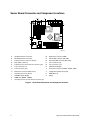
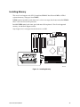
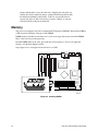
1
Intel® Server Board SAI2 Product Guide A Guide for Technically Qualified Assemblers of Intel® Identified Subassemblies/Products Order Number: A68052-002 Disclaimer Information in this document is provided in connection with Intel® products. No license, express or implied, by estoppel or otherwise, to any intellectual property rights is granted by this document. Except as provided in Intel’s Terms and Conditions of Sale for such products, Intel assumes no liability whatsoever, and Intel disclaims any express or implied warranty, relating to sale and/or use of Intel products including liability or warranties relating to fitness for a particular purpose, merchantability, or infringement of any patent, copyright or other intellectual property right. Intel products are not designed, intended or authorized for use in any medical, life saving, or life sustaining applications or for any other application in which the failure of the Intel® product could create a situation where personal injury or death may occur. Intel may make changes to specifications and product descriptions at any time, without notice. Intel and Pentium are registered trademarks of Intel Corporation or its subsidiaries in the United States and other countries. † Other names and brands may be claimed as the property of others. Copyright © 2001, Intel Corporation. All Rights Reserved. Contents 1 Description Server Board Features ......................................................................................................... 1 Back Panel Connectors ............................................................................................... 3 Server Board Connector and Component Locations .................................................... 4 Processor .................................................................................................................... 5 ServerWorks ServerSet III LE Chipset ......................................................................... 5 Super I/O ..................................................................................................................... 6 Memory........................................................................................................................ 7 PCI I/O Subsystem ...................................................................................................... 7 Video Controller ........................................................................................................... 9 Network Interface Controller (NIC) .............................................................................. 9 Keyboard and Mouse................................................................................................. 10 ACPI .......................................................................................................................... 10 AC Link Mode ............................................................................................................ 11 Wake On LAN............................................................................................................ 11 Security...................................................................................................................... 12 2 Configuration Software and Utilities Hot Keys............................................................................................................................. 15 Power On Self Test (POST) ............................................................................................... 16 Using BIOS Setup Utility..................................................................................................... 17 If You Cannot Access Setup ...................................................................................... 17 Starting Setup............................................................................................................ 17 Setup Menus ............................................................................................................. 17 Menu Selection Bar ................................................................................................... 19 Main Menu................................................................................................................. 19 Advanced Menu......................................................................................................... 20 Security Menu............................................................................................................ 24 System Hardware Menu ............................................................................................ 25 Boot Menu ................................................................................................................. 25 Exit Menu................................................................................................................... 26 Upgrading the BIOS ........................................................................................................... 27 Preparing for the Upgrade ......................................................................................... 27 Upgrading the BIOS................................................................................................... 28 Recovering the BIOS ................................................................................................. 28 Changing the BIOS Language ................................................................................... 29 Hardware Monitoring .......................................................................................................... 30 3 Server Board Installation Tools and Supplies Needed................................................................................................ 31 Before You Begin ............................................................................................................... 31 Emissions Disclaimer................................................................................................. 31 Safety Cautions ......................................................................................................... 31 Safety and Regulatory Compliance .................................................................................... 32 Minimum Hardware Requirements ..................................................................................... 33 iii Installation Notes................................................................................................................ 33 Installation Procedures ....................................................................................................... 34 Install the Front Panel USB Port Filler........................................................................ 34 Replacing the Front Panel Cable ............................................................................... 36 Installing the I/O Shield .............................................................................................. 38 Installing the Processor(s).......................................................................................... 39 Installing Memory....................................................................................................... 43 Configuring Chassis Standoffs................................................................................... 44 Installing Rubber Bumpers......................................................................................... 45 Installing the Server Board......................................................................................... 46 Making Connections to the Server Board................................................................... 48 Cable Routing ............................................................................................................ 49 Finishing Up............................................................................................................... 50 4 Upgrading Tools and Supplies Needed................................................................................................ 51 Cautions ............................................................................................................................. 51 Memory .............................................................................................................................. 52 Processors ......................................................................................................................... 53 Adding or Replacing a Processor............................................................................... 54 Removing a Processor............................................................................................... 57 Replacing the Back up Battery................................................................................... 57 5 Solving Problems Resetting the System ......................................................................................................... 61 Initial System Startup.......................................................................................................... 61 Checklist .................................................................................................................... 61 Running New Application Software..................................................................................... 62 Checklist .................................................................................................................... 62 After the System Has Been Running Correctly ................................................................... 62 Checklist .................................................................................................................... 62 More Problem Solving Procedures ..................................................................................... 63 Preparing the System for Diagnostic Testing ............................................................. 63 Monitoring POST ....................................................................................................... 63 Verifying Proper Operation of Key System Lights ...................................................... 63 Confirming Loading of the Operating System............................................................. 63 Specific Problems and Corrective Actions .......................................................................... 64 Power Light Does Not Light ....................................................................................... 64 No Characters Appear on Screen .............................................................................. 64 Characters Are Distorted or Incorrect......................................................................... 65 System Cooling Fans Do Not Rotate Properly ........................................................... 65 Diskette Drive Activity Light Does Not Light ............................................................... 66 Hard Disk Drive Activity Light Does Not Light ............................................................ 66 CD-ROM Drive Activity Light Does Not Light ............................................................. 66 Cannot Connect to a Server....................................................................................... 66 Problems with Network .............................................................................................. 67 PCI Installation Tips................................................................................................... 67 Problems with Application Software.................................................................................... 68 Bootable CD-ROM Is Not Detected .................................................................................... 68 iv Intel Server Board SAI2 Product Guide 6 Getting Help .................................................................................................................. 69 7 Technical Reference Configuration Jumpers ....................................................................................................... 71 Front Panel Header ............................................................................................................ 72 8 Regulatory and Integration Information Product Regulatory Compliance ......................................................................................... 73 Product Safety Compliance........................................................................................ 73 Product EMC Compliance.......................................................................................... 73 Product Regulatory Compliance Markings ................................................................. 74 Electromagnetic Compatibility Notices................................................................................ 74 FCC (USA) ................................................................................................................ 74 INDUSTRY CANADA (ICES-003) .............................................................................. 75 Europe (CE Declaration of Conformity) ...................................................................... 75 Index ...................................................................................................................................... 77 Contents v Figures 1. 2. 3. 4. 5. 6. 7. 8. 9. 10. 11. 12. 13. 14. 15. 16. 17. 18. 19. 20. 21. 22. 23. 24. 25. 26. 27. 28. 29. 30. 31. Back Panel Connectors ............................................................................................... 3 Server Board Connector and Component Locations .................................................... 4 Removing the Bezel................................................................................................... 34 Inserting the Front Panel USB Port Filler ................................................................... 35 Removing the Front Panel Cable ............................................................................... 36 Installing the SAI2 Front Panel Cable ........................................................................ 37 Installing the I/O Shield.............................................................................................. 38 Lifting the Locking Bar ............................................................................................... 39 Inserting the Processor.............................................................................................. 40 Attaching the Heat Sink and Retention Clip ............................................................... 41 Locking the Heat Sink Retention Clip......................................................................... 42 Attaching the Heat Sink Fan ...................................................................................... 42 Installing Memory....................................................................................................... 43 Configuring Chassis Standoffs................................................................................... 44 Installing Rubber Bumpers......................................................................................... 45 Installing the Server Board......................................................................................... 46 Placing the Server Board in the Chassis.................................................................... 47 Attaching the Server Board........................................................................................ 47 Making Connections to the Server Board................................................................... 48 Routing IDE Cables ................................................................................................... 49 Routing the Floppy Drive Cable ................................................................................. 49 Making Back Panel Connections ............................................................................... 50 Installing DIMMs ........................................................................................................ 52 Lifting the Locking Bar ............................................................................................... 54 Inserting the Processor.............................................................................................. 55 Attaching the Heat Sink Retention Clip ...................................................................... 56 Locking the Heat Sink Retention Clip......................................................................... 56 Attaching the Heat Sink Fan ...................................................................................... 57 Replacing the Backup Battery.................................................................................... 58 Configuration Jumper Location .................................................................................. 71 Front Panel Header Connection Location .................................................................. 72 Tables 1. 2. 3. 4. 5. 6. 7. 8. 9. 10. 11. 12. 13. 14. vi Server Board Features ................................................................................................ 1 Standard VGA Modes.................................................................................................. 9 Security Operation Summary..................................................................................... 12 Configuration Utilities................................................................................................. 15 Hot Keys.................................................................................................................... 15 Keyboard Commands ................................................................................................ 18 On-Screen Options .................................................................................................... 18 Menu Selection Bar ................................................................................................... 19 Main Menu Selections ............................................................................................... 19 Primary/Secondary, Master/Slave Submenu Selections ............................................ 20 Advanced Menu Selections ....................................................................................... 20 Advanced Submenu Selections ................................................................................. 21 Memory Reconfiguration Submenu Selections .......................................................... 21 CPU Reconfiguration Submenu Selections................................................................ 21 Intel Server Board SAI2 Product Guide 15. 16. 17. 18. 19. 20. 21. 22. 23. 24. 25. 26. 27. 28. 29. Contents Peripheral Configuration Submenu Selections........................................................... 22 PCI Device Submenu Selections ............................................................................... 23 Option ROM Submenu Selections ............................................................................. 23 Numlock Submenu Selections ................................................................................... 23 Security Menu Selections .......................................................................................... 24 Secure Mode Submenu Selections............................................................................ 24 Secure Mode Submenu Selections............................................................................ 25 Wake On Event Submenu Selections ........................................................................ 25 Boot Device Priority Submenu Selections.................................................................. 25 Hard Drive Submenu Selections ................................................................................ 26 Removable Devices Submenu Selections ................................................................. 26 Exit Menu Selections ................................................................................................. 26 Monitored Headers and Sensors ............................................................................... 30 Configuration Jumper (JP5) ....................................................................................... 71 Front Panel Header Connection Descriptions ............................................................ 72 vii viii Intel Server Board SAI2 Product Guide 1 Description Server Board Features The Intel® SAI2 server board offers a “flat” design, with the processors and memory subsystems residing on the board. The server board supports dual-processor operation with Intel® Pentium® III processors and the ServerWorks† ServerSet† III LE chipset. The board contains embedded devices for video, network, IDE, and provides basic monitoring hardware and interrupt control for dual-processors and PC/AT compatible operation. Table 1. Server Board Features Feature Description Processor Up to two identical Intel Pentium III (512 or 256 cache) processors for the PGA370 socket that use the Flip Chip Pin Grid Array (FC-PGA) package. Two embedded Voltage Regulating Modules (VRM) support the processors. Chipset ServerWorks ServerSet III LE chipset: • 133-MHz Front Side Bus (FSB) Capability • CNB30LE (North Bridge) • CSB5 (South Bridge) Memory • Dual Inline Memory Module (DIMM) Requirements: 3.3 V, registered ECC DIMMs that are compliant with JEDEC PC133 specification • DIMM Sockets: Four 72-bit, 168-pin, gold contact • DIMMs Supported: 64, 128, 256, 512 MB, and 1GB (Min: 64 MB, Max: 4 GB) • ECC single-bit correction, and multiple-bit detection Video • Integrated onboard ATI† Rage† XL 64-bit SVGA video controller • 8MB SDRAM video memory • SVGA video port BIOS PCI bus 4 MB Flash device for system BIOS Six standard PCI (PCI-33/32-bit) expansion slots for add-in boards • Two 64-bit, 66-MHz, 3.3-V keyed PCI expansion slots • Four 32-bit, 33-MHz, 5-V keyed PCI expansion slots Hard Disk Drive (HDD) • IDE: Primary and secondary, Ultra-ATA 100, maximum four Floppy Disk Drive 3.5-inch CD-ROM Drive E-IDE Network Integrated on-board Intel® EtherExpress™ PRO100+ 10/100 megabit PCI Ethernet† controller (Intel® 82559) with an RJ-45 Ethernet connector continued 1 Table 1. Server Board Features (continued) Feature Description System I/O Super I/O Controller (PC87417) that provides the following: • PS/2†-compatible keyboard and mouse ports, 6-pin DIN • Advanced parallel port, supporting Enhanced Parallel Port (EPP) level 1.7 and 1.9, ECP, compatible 25-pin • Two serial ports, 9-pin • 10/100 BASE-TX, RJ-45 Ethernet port • Two USB ports Power • Power/Sleep Switch with LED Indicator • Wake on LAN† (WOL) • Wake on Ring (WOR) COM 1 only Security • BIOS password • Keyboard password protection • Floppy write-protect Form Factor 2 Server ATX form factor, ATX 2.01 compliant I/O Intel Server Board SAI2 Product Guide Back Panel Connectors 1 ON A B H E C D F G I OM12377 A. B. C. D. E. F. G. H. I. Serial port 1 connector (COM1) Serial port 2 connector (COM2) NMI (Non Maskable Interrupt) switch Keyboard connector Parallel port connector Mouse connector SVGA connector Network connector USB connectors (2) Figure 1. Back Panel Connectors Description 3 Server Board Connector and Component Locations C A B D V E F G H I U T J K L M S R O Q P N OM13065 A 33 MHz/32-bit PCI connectors M Floppy drive connector (FDD) B 66 MHz/64-bit PCI connectors N Primary IDE connector (PRI_IDE) C Primary processor connector (CPU1) O Secondary IDE connector (SEC_IDE) D Back panel connectors P Fan 3 connector (J8) E Primary processor heat sink fan connector (J10) Q Fan 4 connector (J11) F Fan 5 connector (J7) R CSB5 (South Bridge) G Fan 6 connector (J14) S Front panel connector (FRONT_PANEL_HDR) H Main power connector (Main Power) T Configuration jumper block (JP5) I Secondary processor (CPU2) U HDD LED (J12) J CNB30LE (North Bridge) V Battery K DIMM slots (DIMM1 - DIMM4) L Secondary processor heat sink fan connector (J9) Figure 2. Server Board Connector and Component Locations 4 Intel Server Board SAI2 Product Guide Processor The SAI2 server board accommodates one or two 1.0 GHz Intel Pentium III processors with 256K cache support that are designed for the PGA370 socket. The PGA370 is a 370-pin zeroinsertion force (ZIF) socket. The processor(s) interface with the system bus at 133 MHz. For a complete list of supported processors, see: http://support.intel.com/support/motherboards/server/SAI2 Dual Processor Operation The Pentium III processor interface is multi-processor (MP)-ready. Each processor contains a local Intel® Advanced Programmable Interrupt Controller (APIC) section for interrupt handling. When two processors are installed, both processors must be of identical revision, core voltage, and bus/core speeds. Boxed Processor Fan Heat sink The boxed Pentium III processor is supplied with a fan heat sink. After the processor is installed, install and connect the fan heat sink to ensure optimal processor cooling. It is recommended that fan inlet air temperature should be below 45 °C (measured at 0.3 inches above the fan hub). CAUTION Clearance is required around the fan heat sink to ensure unimpeded airflow for proper cooling. Restricting the airflow through the processor heat sink can cause overheating and subsequent failure of the processor. ServerWorks ServerSet III LE Chipset The SAI2 server includes a ServerWorks ServerSet III LE chipset that provides an integrated I/O bridge and memory controller, and a flexible I/O subsystem core (PCI). CNB30LE The CNB30LE is responsible for: • Accepting access requests from the host (processor) bus and for directing those accesses to memory or to one of the PCI buses • Controlling data transfers to and from main memory • Providing the interface for both the 64-bit/66-MHz, Revision 2.2-compliant PCI bus and the 32-bit/33-MHz, Revision 2.2-compliant PCI bus Description 5 CSB5 The CSB5 controller can be both a master and a target on the 32-bit/33-MHz PCI bus and has the following onboard components: • USB controller • IDE controller • Advanced Configuration and Power Interface (ACPI) control registers and is responsible for many power management functions Super I/O The National† PC87417VUL Super I/O Plug-and-Play Compatible with ACPI-Compliant Controller/Extender is used on the SAI2 server board. This device provides the system with: • • • • • • • • Real-time Clock (RTC) Two serial ports One parallel port Floppy disk controller (FDC) PS/2-compatible keyboard and mouse controller General purpose I/O pins Plug-and-Play functions A power management controller The SAI2 server board provides the connector interface for the floppy disk drive, dual serial ports, parallel port, PS/2 mouse and the PS/2 keyboard. Serial Ports Two 9-pin D-Sub connectors are provided on the back panel for serial port A and serial port B. Both ports are compatible with 16550A and 16450 modes. Each serial port can be set to one of four different COM-x ports, and each can be enabled separately. When enabled, each port can be programmed to generate edge- or level-sensitive interrupts. When disabled, serial port interrupts are available to add-in cards. Parallel Port The SAI2 baseboard provides a 25-pin parallel port back panel connector. The Super I/O provides an IEEE 1284-compliant 25-pin bi-directional parallel port. BIOS programming of the Super I/O registers enables the parallel port and determines the port address and interrupt. When disabled, the interrupt is available to add-in cards. Floppy Port The floppy disk connector (FDC1) on the server board provides the interface to the floppy disk drive from the floppy disk controller. 6 Intel Server Board SAI2 Product Guide Keyboard and Mouse Connectors The separate keyboard and mouse connectors, found on the rear panel of the server board, are PS/2-compatible. Memory The SAI2 server board contains four 168-pin DIMM sockets. Memory is partitioned as four banks of registered SDRAM DIMMs, each of which provides 72 bits of non-interleaved memory (64-bit main memory plus ECC). The SAI2 server board supports up to four 3.3-V, registered ECC SDRAM DIMMs that are compliant with the JEDEC PC133 specification. A wide range of DIMM sizes are supported, including 64 MB, 128 MB, 256 MB, 512 MB, and 1 GB DIMMs. The minimum supported memory configuration is 64 MB, using one 64 MB DIMM. The maximum configurable memory size is 4 GB using four 1 GB DIMMs. CAUTION The system will not operate properly if either PC100 DIMMs or non-ECC DIMMs are installed. DIMMs may be installed in one, two, three, or four DIMM slots and must be populated starting with Slot 1 and filling the slots in consecutive order. Empty memory slots between DIMMs are not supported. Although the SAI2 server board architecture allows the user to mix various sizes of DIMMS, Intel recommends that module and DRAM vendors not be mixed in the same server system. ✏ NOTE Use DIMMs that have been tested for compatibility with the server board. Contact your sales representative or dealer for a current list of approved memory modules. Check the Intel Customer Support website for the latest tested memory list: http://support.intel.com/support/motherboards/server/SAI2 PCI I/O Subsystem The expansion capabilities of the SAI2 server board meet the needs of file and application servers for high performance I/O by providing two PCI bus segments in the form of one 64-bit /66 MHz bus segment and one 32-bit /33 MHz bus segment. Description 7 64-bit / 66 MHz PCI Subsystem The 64-bit/66 MHz PCI segment includes two 3.3-V keyed PCI expansion slots that can support 66 MHz, 64/32-bit cards or 33 MHz, 64/32-bit cards. 64-bit PCI features include: • Bus speed up to 66 MHz • 3.3 V signaling environment • Burst transfers up to a peak of 528 Megabytes per second (MBps) • 8-, 16-, 32-, or 64-bit data transfers • Plug-and-Play ready • Parity enabled ✏ NOTE If you install a PCI 33 card into one of the PCI 66/64 connectors, the bus speed for both connectors will be lowered to 33 MHz. 32-bit/33 MHz PCI Subsystem The 32-bit/33 MHz PCI includes the following embedded devices and connectors: • • • • Four 5 V keyed PCI expansion slots Integrated Intel EtherExpress PRO100+ 10/100 megabit PCI Ethernet controller (Intel 82559) Integrated ATI Rage XL video controller with 8 MB of on-board SDRAM CSB5 South Bridge I/O APIC, IDE controller, USB controller, and power management. 32-bit PCI features include: • Bus speed up to 33 MHz • 5-V signaling environment • Burst transfers up to a peak of 132 MBps • 8-, 16-, or 32-bit data transfers • Plug-and-Play ready • Parity enabled 8 Intel Server Board SAI2 Product Guide Video Controller The SAI2 server board includes an ATI Rage XL video controller, 8 MB video SDRAM, and support circuitry for an embedded SVGA video subsystem. The SVGA subsystem supports a variety of modes: up to 1600 X 1200 resolution for CRT displays and up to 1024 x 768 resolution for TFT displays, and up to 16.7 million colors. The SAI2 server board provides a standard 15-pin VGA connector, and external video blanking logic for server management console redirection support. Table 2. Standard VGA Modes Resolution Max. Refresh Rate (Hz) Max. Colors 1280x1024 72 256 1600x1200 85 256 1024x768 100 65K 640x480 100 16.7 M 800x600 100 16.7 M Network Interface Controller (NIC) ✏ NOTE To ensure EMC product regulation compliance, the end system must be used with a shielded LAN cable. The SAI2 server board includes a 10Base-T/100Base-TX network controller that is based on the Intel 82559 Fast Ethernet PCI Bus Controller. As a PCI bus master, the 82559 can burst data at up to 132 MBps resulting in faster frame processing. Status LEDs are included on the external NIC connector. The SAI2 server board provides the ability to disable the embedded NIC in the BIOS Setup option. When disabled it is not visible to the operating system. Description 9 Supported Network Features The 82559 SAI2 supports the following features of the 82559 controller: • Glueless 32-bit PCI Bus Master Interface (Direct Drive of Bus), compatible with PCI Bus Specification, revision 2.1 / 2.2 • Chained memory structure, with improved dynamic transmit chaining for enhanced performance • Programmable transmit threshold for improved bus utilization • Early receive interrupt for concurrent processing of receive data • On-chip counters for network management • Autodetect and autoswitching for 10 or 100 Mbps network speeds • Support for both 10 Mbps and 100 Mbps networks, full or half duplex-capable, with back-to-back transmit at 100 Mbps • Integrated physical interface to TX magnetics • The magnetics component terminates the 100Base-TX connector interface. A flash device stores the network ID. • Support for Wake on LAN (WOL) Keyboard and Mouse The keyboard/mouse controller is PS/2-compatible. The server may be locked automatically if there is no keyboard or mouse activity for a predefined length of time. Once the inactivity (lockout) timer has expired, the keyboard and mouse do not respond until the previously stored password is entered. ACPI The Advance Configuration and Power Interface (ACPI)-aware operating system can place the system into a state where the hard drives spin-down, the system fans stop, and all processing is halted. In this state the power supply is still on and the processors still dissipate some power, such that the power supply fan and processor fans are still running. Note: ACPI requires an operating system that supports this feature. The ACPI sleep states discussed below are defined as: s0: Normal running state s1: Processor sleep state. No content is lost in this state and the processor caches maintain coherency. s4: Hibernate or Save to Disk. The memory and machine state are saved to disk. Pressing the power button or another wakeup event restores the system state from the disk and resumes normal operation. This assumes that no hardware changes were made to the system while it was off. s5: Soft off. Only the RTC section of the chip set is running in this state. The SAI2 server board supports sleep states s0, s1, s4, and s5. When the server board is operating in ACPI mode, the OS retains control of the system and the OS policy determines the entry 10 Intel Server Board SAI2 Product Guide methods and wake-up sources for each sleep state – sleep entry and wake-up event capabilities are provided by the hardware but are enabled by the OS. With future versions of Microsoft Windows† 9X and Windows 2000 that support ACPI, the system BIOS supports only sleep states s0, s1, and s5. CAUTION The system is off only when the AC power is disconnected. AC Link Mode The AC link mode allows the system to monitor its AC input power so that if AC input power is lost and then restored, the system returns to one of the following pre-selected settings: • Power On • Last State (Factory Default Setting) • Stay Off The AC link mode settings can be changed by running the BIOS Setup Utility. Wake On LAN Wake on LAN allows system power to be activated by way of a network or modem. If the system power is set to off, it can be turned on remotely by sending a specific packet from the main computer to the remote system. ✏ NOTE The standard default value of the remote power-on function is “Disabled”. The Wake on LAN / Ring function can be changed by setting the option to “Enabled” in the BIOS Setup Utility. Description 11 Security The SAI2 BIOS provides a number of security features. This section describes the security features and their operation. Table 3. Security Operation Summary Mode Entry Method/ Event Entry Criteria Secure Mode Keyboard inactivity timer. Runtime activation of KBC hot key Secure Boot User Password on boot (AT style) Behavior Exit Criteria After Exit User password enabled in Setup Floppy writes are disabled (if selected in Setup). Except password, no mouse or keyboard input is accepted. User password followed by [Enter] Floppy writes are enabled. Keyboard and mouse inputs are accepted. Power On/Reset User password and Secure Boot enabled in Setup Enter Secure Mode just before boot. (see above for Secure Mode behavior.) User password followed by [Enter] System attempts to boot normally. System exits Secure Mode. (see above for Secure Mode behavior.) Power On/Reset User password set and password on boot enabled System halts for User Password before booting. The system is not in secure mode. Except password, no mouse or keyboard input is accepted. User password followed by [Enter] Power and Reset switches are enabled. Keyboard and mouse inputs are accepted. The system boots normally. Boot sequence is determined by setup options. Password Protection The BIOS uses passwords to prevent unauthorized tampering with the system. Once secure mode is entered, access to the system is allowed only after the correct password(s) has been entered. Both user and supervisor passwords are supported by the BIOS. The user password cannot be set unless a supervisor password has been set. When set, a password can be cleared by changing it to a null string. Clearing the supervisor password also clears the user password. Entering the user password permits modification of the time, date, language, user password, and password on boot setup fields; other setup fields can be modified only if the supervisor password is entered. The user password also allows the system to boot, if secure boot is enabled. If a wrong password is entered three times in a row, the BIOS stops validating passwords and the BIOS security engine returns a failure for any further password validation attempt. If the user enters three wrong passwords in a row during the boot sequence (i.e., when entering Setup), the system is placed into a halt state. This feature makes is difficult to break the password by the “trial and error” method. 12 Intel Server Board SAI2 Product Guide Using Passwords If only the supervisor password is set, you: • Must enter the supervisor password to enter BIOS Setup. • Must enter the supervisor password to boot the server if Password on Boot is enabled in the BIOS Setup. • Must enter the supervisor password to exit secure mode. If both passwords are set, you: • May enter the user password to enter BIOS Setup. However, you will not be able to change many of the options. • Must enter the supervisor password if you want to enter BIOS Setup and have access to all of the options. • May enter either password to boot the server if Password on Boot is enabled in the BIOS Setup. • May enter either password to exit secure mode. Hot Key Activation A hot key combination allows the user to activate secure mode immediately instead of waiting for the inactivity time-out to expire. The hot key combination is configured through Setup, with the following keys are configurable as valid hot keys: Ctrl-Alt <A-Z, 0-9>. Password Clear Jumper If the user or supervisor password(s) is(are) lost or forgotten, moving the password clear jumper into the “clear” position clears both passwords. The password clear jumper must be restored to its original position before a new password(s) can be set. The password clear jumper is located on jumper block ‘JP5’ pins [3-4] on the SAI2 board. Floppy Write Protection When selected in Setup, the floppy write protection option blocks writes to the floppy disk when the system is in secure mode. Floppy write protection is in effect only while the system is in secure mode. When not in secure mode, write protection is disabled and the floppy diskette drive operates normally. Secure Boot Mode (Unattended Start) The Secure Boot mode allows the system to boot and run the operating system (OS) without requiring the user password, even if the user password is set. However, until the user password is entered, mouse and keyboard input is not accepted (except for password entry). If Secure Boot is enabled, secure mode is enabled shortly before boot. To prevent unauthorized tampering with any option ROM based setup utilities, enable the ‘Option ROM Menu Mask’ setting in the security menu. Description 13 Using Secure Boot Configure and enable the secure boot mode. When secure mode is in effect: • You can boot the server and the operating system will run, but you must enter the user password to use the keyboard or mouse. • You cannot turn off system power or reset the server from the front panel switches. Secure mode has no effect on functions enabled via the Server Manager Module or power control via the real time clock. Taking the server out of secure mode does not change the state of system power. That is, if you press and release the power switch while secure mode is in effect, the system will not be powered off when secure mode is later removed. However, if the front panel power switch remains depressed when secure mode is removed, the server will be powered off. Fixed Disk Boot Sector Write Protect The fixed disk write protect switch is set to ‘Write Protect’ to prevent writes to the fixed IDE disk boot sector. This feature works only with IDE drives and only the boot sector is write protected. Power Switch Mask The power switch mask enables and disables the power switch feature. If set to masked, the system power cannot be turned off with the power switch after booting the OS. Termination is also disabled. Termination is a feature that terminates system power when the power switch is held down for more than four seconds. 14 Intel Server Board SAI2 Product Guide 2 Configuration Software and Utilities This chapter describes the Power On Self Test (POST) and server configuration utilities. The table below briefly describes the utilities. Table 4. Configuration Utilities Utility Description and brief procedure Page BIOS Setup If the system does not have a diskette drive, or the drive is disabled or mis-configured, use Setup to enable it. 17 Or, you can move the CMOS jumper on the server board from the default setting (Protect CMOS memory) to the Clear setting; this will allow most server configurations to boot. Then use the recovery disk to recover. BIOS Upgrade Utility Use to upgrade the BIOS. 27 Hot Keys Use the keyboard’s numeric pad to enter numbers and symbols. Table 5. Hot Keys To do this: Press these keys Clear memory and reload the operating systemthis is a system reset. <Ctrl+Alt+Del> Secure your system immediately. The following keys are configurable as valid hot keys: <Ctrl+Alt>+<A-Z, 0-9>. (Set your hot key combination with Setup.) 15 Power On Self Test (POST) Each time you turn on the system, POST starts running. POST checks the server board, processor, memory, keyboard, and most installed peripheral devices. During the memory test, POST displays the amount of memory that it is able to access and test. The length of time needed to test memory depends on the amount of memory installed. POST is stored in flash memory. 1. Turn on your video monitor and server. After a few seconds POST begins to run. 2. After the memory test, these screen prompts and messages appear: Press <F2> key if you want to run SETUP 3. If you do not press <F2> and do NOT have a device with an operating system loaded, the above message remains for a few seconds while the boot process continues, and the system beeps once. Then this message appears: Operating system not found 4. Press <Esc> during POST to pop up a boot menu when POST finishes. From this menu you can choose the boot device or enter BIOS Setup. After POST completes, the system beeps once. What appears on the screen after this depends on whether you have an operating system loaded and if so, which one. If the system halts before POST completes running, it emits a beep code indicating a fatal system error that requires immediate attention. If POST can display a message on the video display screen, it causes the speaker to beep twice as the message appears. Note the screen display and write down the beep code you hear; this information is useful for your service representative. For a listing of beep codes and error messages that POST can generate, see the “Solving Problems” chapter in this manual. 16 Intel Server Board SAI2 Product Guide Using BIOS Setup Utility This section describes the BIOS Setup Utility options. Use Setup to change the server configuration defaults. You can run Setup with or without an operating system being present. If You Cannot Access Setup If the diskette drive is misconfigured so that you cannot access it to run a utility from a diskette, you may need to clear CMOS memory. You will need to open the server, change a jumper setting, use Setup to check and set diskette drive options, and change the jumper back. For a step-by-step procedure, see Chapter 5, under the heading, “CMOS Jumper.” Starting Setup You can enter and start Setup under several conditions: • When you turn on the server, after POST completes the memory test • When you have moved the CMOS jumper on the server board to the “Clear CMOS” position (enabled); for the procedure, see Chapter 5, under the heading “CMOS Jumper” In the three conditions listed above, after rebooting, you will see this prompt: Press <F2> to enter SETUP In a fourth condition, when CMOS/NVRAM has been corrupted, you will see other prompts but not the <F2> prompt: Warning: Warning: CMOS checksum invalid CMOS time and date not set In this condition, the BIOS will load default values for CMOS and attempt to boot. Setup Menus Each Setup menu page contains a number of features. Except those used for information purposes, each feature is associated with a value field that contains user-selectable parameters. Parameters may be changed depending upon the security option chosen. If a value is not changeable due to insufficient security privileges (or other reasons), the feature’s value field becomes inaccessible. The bottom portion of the Setup screen provides a list of commands that are used for navigating the Setup utility. Configuration Software and Utilities 17 Table 6. Keyboard Commands Press Description <F1> Help - Pressing F1 on any menu invokes the general Help window ←→ The left and right arrow keys are used to move between the major menu pages. The keys have no affect if a submenu or pick list is displayed. ↑ Select Item up - The up arrow is used to select the previous value in a menu item’s option list, or a value field pick list. Pressing the Enter key activates the selected item. ↓ Select Item down - The down arrow is used to select the next value in a menu item’s option list, or a value field pick list. Pressing the Enter key activates the selected item. F5/- Change Value - The minus key or the F5 function key is used to change the value of the current item to the previous value. This key scrolls through the values in the associated pick list without displaying the full list. F6/+ Change Value - The plus key or the F6 function key is used to change the value of the current menu item to the next value. This key scrolls through the values in the associated pick list without displaying the full list. On 106-key Japanese keyboards, the plus key has a different scan code than the plus key on the other keyboard, but it has the same effect. <Enter> Execute Command - The Enter key is used to activate submenus when the selected feature is a submenu, or to display a pick list if a selected feature has a value field, or to select a sub-field for multi-valued features like time and date. If a pick list is displayed, the Enter key will undo the pick list, and allow another selection in the parent menu. <Esc> Exit - The ESC key provides a mechanism for backing out of any field. This key will undo the pressing of the Enter key. When the ESC key is pressed while editing any field or selecting features of a menu, the parent menu is re-entered. When the ESC key is pressed in any submenu, the parent menu is re-entered. When the ESC key is pressed in any major menu, the exit confirmation window is displayed and the user is asked whether changes can be discarded. <F9> Setup Defaults - Pressing F9 causes the following to appear: Setup Confirmation Load default configuration now? [Yes] [No] If “Yes” is selected and the Enter key is pressed, all Setup fields are set to their default values. If “No” is selected and the Enter key is pressed, or if the ESC key is pressed, the user is returned to where they were before F9 was pressed without affecting any existing field values. <F10> Save and Exit - Pressing F10 causes the following message to appear: Setup Confirmation Save Configuration changes and exit now? [Yes] [NO] If “Yes” is selected and the Enter key is pressed, all changes are saved and Setup is exited. If “No” is selected and the Enter key is pressed, or the ESC key is pressed, the user is returned to where they were before F10 was pressed without affecting any existing values. Table 7. On-Screen Options When you see this: What it means On screen, an option is shown but you cannot select it or move to that field. You cannot change or configure the option in that menu screen. Either the option is auto-configured or auto-detected, or you must use a different Setup screen. Press <Enter> to display a submenu that is either a separate full screen menu or a popup menu with one or more choices. On screen, the phrase Press Enter appears next to the option. 18 Intel Server Board SAI2 Product Guide Menu Selection Bar The Menu Selection Bar is located at the top of the screen and displays the major menu selections available to the user as shown in Table 8: Table 8. Main Menu Selection Bar Advanced Security Allocates resources for hardware components Configures Sets and clears advanced passwords and features available security features through the chipset System Boot Exit Configures power management features Selects boot options and power supply controls Saves or discards changes to Setup program options Main Menu You can make the following selections on the Main Menu. Use the submenus for other selections. Table 9. Main Menu Selections Feature Choices Description Processor Type Processor Speed Cache RAM System Memory Extended Memory Language None, information only None, information only None, information only None, information only None, information only English (US) Français Deutsch Italiano Español HH:MM:SS Shows processor type Shows processor speed Lists size of cache RAM Lists amount of system memory installed Lists amount of extended memory installed Selects which language the BIOS displays. Note: This feature immediately changes the BIOS to the language selected. System Time System Date Diskette A Diskette B Hard Disk Pre-Delay Primary Master Primary Slave Secondary Master Secondary Slave MM/DD/YYYY Not installed 1.2MB, 5.25 inch 1.44/1.25 MB, 3.5-inch 2.88 MB Disabled 1.2MB, 5.25 inch 1.44/1.25 MB, 3.5-inch 2.88 MB Disable 3 Seconds 6 Seconds 9 Seconds 12 Seconds 15 Seconds 21 Seconds 30 Seconds <Enter> <Enter> <Enter> <Enter> Configuration Software and Utilities Sets the system time (hour, minutes, seconds, on 24 hour clock). Sets the system date (month, day, year). Selects the diskette type. Note: 1.25 MB, 3.5 inch references a 1024 byte/sector Japanese media format. To support this type of media format requires a 3.5-inch, 3-mode diskette drive. Selects the diskette type. Note: 1.25 MB, 3.5 inch references a 1024 byte/sector Japanese media format. To support this type of media format requires a 3.5-inch, 3-mode diskette drive. Delays fist access to disk to ensure the disk is initialized by the BIOS before any accesses. Displays IDE device selection. Displays IDE device selection. Displays IDE device selection. Displays IDE device selection. Enters submenu. Enters submenu. Enters submenu. Enters submenu. 19 Table 10. Primary/Secondary, Master/Slave Submenu Selections Feature Choices Description Type Auto None CD-ROM ATAPI Removable IDE Removable Other ATAPI User Select the type of device that is attached to the IDE channel. If User is selected, you will need to enter the parameters of the IDE device (cylinders, heads and sectors). Mult-Sector Transfers Disable 2 Sectors 4 Sectors 8 Sectors 16 Sectors Specifies the number of sectors that are transferred per block during multiple sector transfers. LBA Mode Control Disabled Enabled Enables Large Block Addressing instead of cylinder, head, sector addressing. 32 Bit I/O Disabled Enabled Enables 32Bit IDE data transfers. Transfer Mode Standard Fast PIO 1 Fast PIO 2 Fast PIO 3 Fast PIO 4 FPIO 3/ DMA 1 FPIO 4 / DMA 2 Select the method of moving data to and from the hard drive. (If Standard is select, optimum transfer mode will be selected). Ultra DMA Mode Disabled Enabled Enables Ultra DMA mode. Advanced Menu You can make the following selections on the Advanced Menu as shown in Table 11. Use the submenus found in Tables 12 – 18 for the other selections that appear in the Advanced Menu. Table 11. Advanced Menu Selections Feature 20 Choices Description Advanced <Enter> Refer to Advanced Submenu. Memory Reconfiguration <Enter> Refer to Memory Reconfiguration Submenu. CPU Reconfiguration <Enter> Refer to CPU Reconfiguration Submenu. Peripheral Configuration <Enter> Refer to Peripheral Reconfiguration Submenu. PCI Device <Enter> Refer to PCI Device Submenu. Option ROM <Enter> Refer to Option ROM Submenu. It Disables/Enables the Option ROM BIOS on the PCI Bus. Numlock <Enter> Refer to Numlock Submenu. Intel Server Board SAI2 Product Guide Table 12. Advanced Submenu Selections Feature Choices Description Installed OS Other PnP O/S Selects the type of operation system that is used most. Reset Configuration Data No Yes Clears the Extended System Configuration Data if selected. Boot-time Diagnostic Screen Disabled Enabled Enable/Disable boot-time diagnostic screen. Splash screen is displayed over the diagnostic screen when is option is Disabled. POST Error Pause Disabled Enabled Pauses and displays SETUP entry or resume boot prompt if error occurs on boot. If disabled, system always attempts to boot. Table 13. Memory Reconfiguration Submenu Selections Feature Choices or Display Only DIMM #1 Status Normal None Error (DIMM Row Error) This field is informational only. DIMM #2 Status Normal None Error (DIMM Row Error) This field is informational only. DIMM #3 Status Normal None Error (DIMM Row Error) This field is informational only. DIMM #4 Status Normal None Error (DIMM Row Error) This field is informational only. Description Clear DIMM Error Press <Enter> Clears the DIMM group error status information. DIMM Error Pause Enabled Disabled If enabled, the POST operation pauses if a DIMM error occurs. Table 14. CPU Reconfiguration Submenu Selections Feature Processor #1 Status Processor #2 Status Clear Processor Errors Processor Pause Choices Normal None Error (CPU Error) Normal None Error (CPU Error) Press <Enter> Enabled Disabled Configuration Software and Utilities Description (Display Only) (Display Only) Clears the processor error information. If enabled, the POST operation pauses if a processor error occurs. 21 Table 15. Peripheral Configuration Submenu Selections Feature Choices Description Serial Port 1 Disabled 3F8, IRQ 3 3F8, IRQ 4 2F8, IRQ 3 2F8, IRQ 4 3E8, IRQ 3 3E8, IRQ 4 2E8, IRQ 3 2E8, IRQ 4 Auto Disables serial port 1 or selects the base address and interrupt (IRQ) for serial port 1. Disabled 3F8, IRQ 3 3F8, IRQ 4 2F8, IRQ 3 2F8, IRQ 4 3E8, IRQ 3 3E8, IRQ 4 2E8, IRQ 3 2E8, IRQ 4 Auto Disables serial port 2 or selects the base address and interrupt (IRQ) for serial port 2. Disabled 398, IRQ 5 378, IRQ 7 278, IRQ 5 278, IRQ 7 3BC, IRQ 5 3BC, IRQ 7 Auto Disables the parallel port or selects the base address and interrupt (IRQ) for the Parallel port. Parallel Mode Output only Bi-directional EPP ECP, DMA 1 ECP, DMA 3 Selects parallel port operation mode. Diskette Controller Disabled Enabled Disables/Enables the floppy disk controller. Mouse Disabled Enabled Auto Detect Disabled prevents any installed PS/2 mouse from functioning, but frees up IRQ12. Enabled forces the PS/2 mouse port to be enabled regardless if a mouse is present. Auto Detect enables the PS/2 mouse only if present. OS Controlled is displayed if the OS controls the mouse. LAN Controller Disabled Enabled Disables/Enables on-board LAN controller. VGA Controller Enabled Disabled Disables/Enables on-board Video controller. USB Controller Disabled Enabled Enables/Disables on-board USB controller. IDE Controller Disabled Primary Secondary Both Enables/Disables on-board IDE controller. Serial Port 2 Parallel Port 22 Auto forces BIOS to configure the port. Auto forces BIOS to configure the port. Auto forces BIOS to configure the port. Intel Server Board SAI2 Product Guide Table 16. PCI Device Submenu Selections Feature Choices Description PCI IRQ 2 through 13 and PCI IRQ 15 Disabled Auto Select IRQ3 IRQ4 IRQ5 IRQ6 IRQ7 IRQ9 IRQ10 IRQ11 IRQ12 Specify which PIC IRQ a certain PCI IRQ maps to Table 17. Option ROM Submenu Selections Feature Choices Description On Board LAN Enabled Disabled Disables/Enables option ROM expansion for the onboard LAN option ROM. PCI Slot 1 Enabled Disabled Disables/Enables the expansion of the option ROM for devices in PCI slot 1 PCI Slot 2 Enabled Disabled Disables/Enables the expansion of the option ROM for devices in PCI slot 2 PCI Slot 3 Enabled Disabled Disables/Enables the expansion of the option ROM for devices in PCI slot 3 PCI Slot 4 Enabled Disabled Disables/Enables the expansion of the option ROM for devices in PCI slot 4 PCI Slot 5 Enabled Disabled Disables/Enables the expansion of the option ROM for devices in PCI slot 5 PCI Slot 6 Enabled Disabled Disables/Enables the expansion of the option ROM for devices in PCI slot 6 Table 18. Numlock Submenu Selections Feature Choices Description Numlock Auto On Off Selects the power on state for Num Lock. Key Click Disabled Enabled Enables or disables the audible key-click. Keyboard auto-repeat rate 2/sec 6/sec 10/sec 13.3/sec 18.5/sec 21.8/sec 26.7/sec 30/sec Sets the number of times per second a key will repeat while it is held down. Keyboard auto-repeat delay 1/4 sec 1/2 sec 3/4 sec 1 sec Sets the delay before a key starts to repeat when it is held down. Configuration Software and Utilities 23 Security Menu You can make the following selections on the Security Menu. Enabling the Supervisor Password field requires a password for entering Setup. The passwords are not case-sensitive. Table 19. Security Menu Selections Feature Supervisor Password is User Password is Choices Clear Set Supervisor Password <Enter> Set User Password <Enter> Password on Boot Disabled Enabled Diskette Access Everyone Supervisor Floppy Write Protect Disabled Enabled Write protects floppy drive. Fixed Disk Boot Sector Secure Mode Normal Write Protect <Enter> Protects the boot sector on the boot drive against some viruses. Power Switch Mask Masked Unmasked Determines whether power switch functions from front panel Processor Serial Number Disabled Enabled Determines whether the processor serial number feature is enabled or disabled. Table 20. Enters Secure Submenu. This is only available if both the user and supervisor passwords are set. Secure Mode Submenu Selections Feature Secure Mode Timer Secure Mode HotKey Secure Mode Boot 24 Clear Description (Display only). Once set, this can be disabled by setting it to a null string, or by clearing password jumper on system board. (Display only). Once set, this can be disabled by setting it to a null string, or by clearing password jumper on system board. Supervisor password controls access to the setup utility. When the <Enter> key is pressed, the user is prompted for a password; press ESC key to abort. Once set, this can be disabled by setting it to a null string, or by clearing password jumper on system board. When the <Enter> key is pressed, the user is prompted for a password; press ESC key to abort. Once set, this can be disabled by setting it to a null string, or by clearing password jumper on system board. Requires password entry before boot. System will remain in secure mode until password is entered. Password on Boot takes precedence over Secure Mode Boot. Limits the use of the diskette drive to system supervisors. Supervisor password must be set to enable this feature. Choices Disabled 1 Min 2 Min 5 Min 10 min 30 min 1 Hr 2 Hr Disabled Enabled Disabled Enabled Description Period of keyboard and mouse inactivity before secure mode is activated and a password is required gain access. Enables/Disables the ability to lock the system with a <CTRL>+<ALT> + <key> combination. The key can be selected and submenu appears when enabled. A password is required to gain access. Enables/Disables secure boot. The system boots normally, but a password is required to access the system using any PS/2 device. Intel Server Board SAI2 Product Guide System Hardware Menu You can make the following selections on the Server Menu. Table 21. Secure Mode Submenu Selections Feature Choices Description Wake On Event <Enter> Enters Wake On Event submenu. AC-Link Stay Off Last State Power On Sets what happens when AC power is lost and restored. Stay Off means the server will not power up. Last State means the server will power up as it was powered when AC was lost. Power On means the server will always power up when AC is regained. Error Log Initialization <Enter> Select to clear the System Error Log. If Clear OK, then display “System Event Log Cleared!” If Clear failed, then display “System Event Log Not Cleared!” Table 22. Wake On Event Submenu Selections Feature Choices Description Wake On LAN Disabled Enabled Enables remote power on via network command. Wake On Ring Disabled Enabled Enables remote power on via serial port. Console Connection Direct Via Modem Indicates whether the console is connected directly to the system or if a modem is used to connect. Boot Menu Boot Menu options allow the user to select the boot device. The following table is an example of a list of devices ordered in priority of the boot invocation. Items can be re-prioritized by using the up and down arrow keys to select the device. Once the device is selected, use the plus (+) key to move the device higher in the boot priority list. Use the minus (-) key to move the device lower in the boot priority list. Table 23. Boot Device Priority Submenu Selections Boot Priority Device Description 1 ATAPI CD-ROM Drive Attempts to boot from an ATAPI CD-ROM drive. 2 Removable Devices Attempts to boot from a removable device. 3 Hard Drive Attempts to boot from a hard drive device. 4 Intel® Boot Agent, Version 4.0.17 Attempts to boot from a network connection. Requires the presence of a PXE server. Configuration Software and Utilities 25 Table 24. Hard Drive Submenu Selections Boot Priority Device Description 1 Hard Drive 1* Select the order in which each drive is attempted to be used as the boot device. 2 Hard Drive 2* Auto-detected hard drive. 3 Hard Drive 3* Auto-detected hard drive. 4 Bootable Add in Card Auto-detected Add-in card. * These selections change depending on the system configuration. Table 25. Removable Devices Submenu Selections Boot Priority Device Description 1 Legacy Floppy Drives Select the order in which each removable device attempts to be used as the boot device. **These selections will change depending on the system configuration Exit Menu You can make the following selections on the Exit Menu. Select an option using the up or down arrow keys; then press <Enter> to execute the option. Pressing <Esc> does not exit this menu. You must select one of the items from the menu or menu bar to exit. Table 26. 26 Exit Menu Selections Choices Description Exit Saving Changes Exit after writing all modified Setup item values to CMOS. Exit Discarding Changes Exit leaving CMOS unmodified. User is prompted if any of the setup fields were modified. Load Setup Defaults Load default values for all SETUP items. Discard Changes Read previous values of all Setup items from CMOS. Save Changes Write all Setup item values to CMOS. Intel Server Board SAI2 Product Guide Upgrading the BIOS Preparing for the Upgrade Before you upgrade the BIOS, prepare for the upgrade by recording the current BIOS settings, obtaining the upgrade utility, and making a copy of the current BIOS. Recording the Current BIOS Settings 1. Boot the computer and press <F2> when you see the message: Press <F2> Key if you want to run SETUP 2. Write down the current settings in the BIOS Setup program. ✏ NOTE Do not skip step 2. You will need these settings to configure your computer at the end of the procedure. Obtaining the Upgrade Utility You can upgrade to a new version of the BIOS using the new BIOS files and the BIOS upgrade utility, PHLASH.EXE. You can obtain the BIOS upgrade file and the PHLASH.EXE utility through your computer supplier or from the Intel Customer Support website: http://support.intel.com/support/motherboards/server/SAI2 ✏ NOTE Please review the instructions distributed with the upgrade utility before attempting a BIOS upgrade. This upgrade utility allows you to: • Upgrade the BIOS in flash memory. • Update the language section of the BIOS. The following steps explain how to upgrade the BIOS. Creating a Bootable Diskette 1. Use a DOS or Windows 95 system to create the diskette. 2. Insert a diskette in diskette drive A. 3. At the C:\ prompt, for an unformatted diskette, type: format a:/s or, for a formatted diskette, type: sys a: 4. Press <Enter>. Configuration Software and Utilities 27 Creating the BIOS Upgrade Diskette The BIOS upgrade file is a compressed self-extracting archive that contains the files you need to upgrade the BIOS. 1. Insert the bootable diskette into the diskette drive. 2. Extract the contents of the BIOS.EXE file onto the bootable diskette. To do this, simply type the filename (with or without the extension) at the a:\ prompt, for example “BIOS.EXE”. 3. You will be prompted to confirm a folder in which to store the extracted files. The BIOS upgrade image is extracted in the specified folder. Upgrading the BIOS 1. Place the bootable diskette containing the BIOS update files into the diskette drive of your system. Boot the system with the diskette is in the drive. 2. At this point you have a choice of two options. Press 1 and ENTER to automatically update the system BIOS. This will update the system BIOS and reset the system. Press 2 and ENTER to update the User Binary and reset the system. 3. Wait while the BIOS files are updated. Do not power down the system during the BIOS update process! The system will reset automatically when the BIOS update process is completed. Remove the diskette from the diskette drive. 4. Check to make sure the BIOS version displayed during POST is the new version as the system reboots. 5. Enter Setup by pressing the F2 key during boot. Once in Setup, press the F9 and ENTER to set the parameters back to default values. 6. Re-enter the values you wrote down at the beginning of this process. Press F10 and ENTER to exit BIOS Setup and Save Changes. 7. If you do not set the CMOS values back to defaults using the F9 key, the system may function erratically. ✏ NOTE You may encounter a CMOS Checksum error or other problem after reboot. Try shutting down the system and booting up again. CMOS checksum errors require that you enter Setup, check your settings, save your settings, and exit Setup. Recovering the BIOS It is unlikely that anything will interrupt the BIOS upgrade; however, if an interruption occurs, the BIOS could be damaged. The following steps explain how to recover the BIOS if an upgrade fails. ✏ NOTE Because of the small amount of code available in the non-erasable boot block area, there is no video support. You will not see anything on the screen during the procedure. Monitor the procedure by listening to the speaker. You must boot to DOS. The BIOS recovery diskette will not be created correctly under the DOS window of a Windows operating system. 28 Intel Server Board SAI2 Product Guide 1. Obtain the BIOS update file package from Intel’s http://support.intel.com web site. 2. A file called “crisis.zip” is one of the files included with each SAI2 BIOS release file package. Unzip the “crisis.zip” file to a directory on your hard drive. 3. Format a blank diskette (the diskette should not be a bootable DOS diskette). Insert the diskette into the diskette drive. 4. From the MS-DOS prompt on an MS-DOS system, run the “crisdisk.bat” file from the directory you created on your hard drive. Follow the instructions on the screen to create the BIOS recovery diskette. ✏ NOTE The BIOS recovery diskette will not be created correctly under the MS-DOS window of a Windows operating system. It is necessary to use an MS-DOS system to create the BIOS recovery floppy diskette. 5. Power off the SAI2 system, unplug the power cord, and remove the chassis panel. 6. Remove the spare jumper from pins 11-12 on jumper block JP5 and install it on pins 9-10 (BIOS Recovery) of jumper block JP5. 7. Insert the BIOS recovery diskette into the diskette drive. 8. Reinstall the chassis panel, plug in the power cord(s), and power on the system. 9. The screen will remain blank while the BIOS Recovery is performed. A number of beeps will occur during the BIOS update. The diskette drive access light will not turn off when the BIOS recovery is completed. Allow four minutes for the BIOS recovery to complete. If a POST card is installed in a PCI slot during the BIOS recovery, you can tell that the BIOS recovery is complete when code “EC” is displayed. When the BIOS Recovery is complete, it is safe to power off the system. 10. Power off the system, unplug the power cord(s), and remove the chassis panel. 11. Remove the BIOS Recovery jumper from pins 9-10 and store the jumper on pins 11-12. 12. Replace the chassis panel, plug in the power cord(s), and power on the system. 13. Perform a CMOS clear following the BIOS recovery. Changing the BIOS Language You can use the BIOS upgrade utility to change the language the BIOS uses for messages and the Setup program. Use a bootable diskette containing the Intel flash utility and language files. 1. Boot the computer with the bootable diskette in drive A. The BIOS upgrade utility screen appears. 2. Select Update Flash Memory From a File. 3. Select Update Language Set. Press <Enter>. 4. Select drive A and use the arrow keys to select the correct .lng file. Press <Enter>. 5. When the utility asks for confirmation that you want to flash the new language into memory, select Continue with Programming. Press <Enter>. 6. When the utility displays the message upgrade is complete, remove the diskette. Press <Enter>. 7. The computer will reboot and the changes will take effect. Configuration Software and Utilities 29 Hardware Monitoring The SAI2 server board has an integrated Winbond† Heceta† chip that is responsible for hardware monitoring. Together, the Winbond Heceta chip and the Winbond Hardware Doctor† software provide basic server hardware monitoring which alerts a system administrator if a hardware problem occurs on an Intel® Server Board SAI2-based system. The Winbond Hardware Doctor software is for use with Windows 2000 Server and Windows 2000 Advanced Server† operating systems. Below is a table of monitored headers and sensors on the SAI2 server board. Table 27. Monitored Headers and Sensors Voltage Fan Speed Temperature Item Description CPU1 Monitors primary processor voltage. CPU2 Monitors secondary processor voltage. VCC3 Monitors VCC3. VCC Monitors VCC. +12V Monitors +12V. VTT Monitors VTT (AGTL bus termination voltage). 2.5V Monitors 2.5V. 5VSB Monitors 5VSB (5V stand-by). CPU1_FAN Monitors primary processor fan speed. CPU2_FAN Monitors secondary processor fan speed. CHASSIS_FAN Monitors chassis fan speed through chassis fan header 3 only. CPU2 Monitors primary processor temperature. CPU1 Monitors secondary processor temperature. CHASSIS Monitors chassis ambient temperature. Winbond Hardware Doctor software and a white paper that provides more information on using Winbond Hardware Doctor software are available on the Intel Server Board SAI2 Resource CD and are also available for download at: http://www.support.intel.com/support/motherboards/server/SAI2 30 Intel Server Board SAI2 Product Guide 3 Server Board Installation Tools and Supplies Needed • • • • • Phillips† (cross head) screwdriver (#1 bit and #2 bit) Needle nosed pliers A ruler Pen or pencil Antistatic wrist strap and conductive foam pad (recommended) Before You Begin Emissions Disclaimer To ensure EMC compliance with your local regional rules and regulations, the final configuration of your end system product may require additional EMC compliance testing. For more information please contact your local Intel Representative. See “Regulatory and Integration Information” on page 73 for product Safety and EMC regulatory compliance information. This is an FCC Class A device. Integration of it into a Class B chassis does not result in a Class B device. Safety Cautions CAUTIONS System power on/off: The power button DOES NOT turn off the system AC power. To remove power from system, you must unplug the AC power cord from the wall outlet. Make sure the AC power cord is unplugged before you open the chassis, add, or remove any components. Hazardous conditions, devices & cables: Hazardous electrical conditions may be present on power, telephone, and communication cables. Turn off the server and disconnect the power cord, telecommunications systems, networks, and modems attached to the server before opening it. Otherwise, personal injury or equipment damage can result. Electrostatic discharge (ESD) & ESD protection: ESD can damage disk drives, boards, and other parts. We recommend that you perform all procedures in this chapter only at an ESD workstation. If one is not available, provide some ESD protection by wearing an antistatic wrist strap attached to chassis groundany unpainted metal surfaceon your server when handling parts. 31 ESD and handling boards: Always handle boards carefully. They can be extremely sensitive to ESD. Hold boards only by their edges. After removing a board from its protective wrapper or from the server, place the board component side up on a grounded, static free surface. Use a conductive foam pad if available but not the board wrapper. Do not slide board over any surface. Installing or removing jumpers: A jumper is a small plastic encased conductor that slips over two jumper pins. Some jumpers have a small tab on top that you can grip with your fingertips or with a pair of fine needle nosed pliers. If your jumpers do not have such a tab, take care when using needle nosed pliers to remove or install a jumper; grip the narrow sides of the jumper with the pliers, never the wide sides. Gripping the wide sides can damage the contacts inside the jumper, causing intermittent problems with the function controlled by that jumper. Take care to grip with, but not squeeze, the pliers or other tool you use to remove a jumper, or you may bend or break the stake pins on the board. Safety and Regulatory Compliance See “Regulatory and Integration Information” on page 73 for product Safety and EMC regulatory compliance information. Intended uses: This product was evaluated for use in servers that will be installed in offices, computer rooms, and similar locations. Other uses require further evaluation. EMC testing: Before computer integration, make sure that the chassis, power supply, and other modules have passed EMC testing using a server board with a microprocessor from the same family (or higher) and operating at the same (or higher) speed as the microprocessor used on this server board. Server board diagram label provided: Place the label inside the chassis in an easy-to-see location, preferably oriented similarly to the server board. 32 Intel Server Board SAI2 Product Guide Minimum Hardware Requirements To avoid integration difficulties and possible board damage, your system must meet the following minimum requirements. For a list of qualified memory and chassis components see: http://support.intel.com/support/motherboards/server/SAI2 Processor Minimum of one 1.0 GHz Intel Pentium III processor with 256K cache support. For a complete list of supported processors, see: http://support.intel.com/support/motherboards/server/SAI2 Memory Minimum of 64 MB of 133 MHz, 3.3 V, ECC, PC/133 compliant registered SDRAM on 168 pin gold DIMMs. Power Supply Minimum of 250 W with 0.8 A +5 V standby current (in order to support Wake On LAN (WOL)). You must provide standby current, or the board will not boot. Installation Notes Installation Process Quick Reference Step Install the primary processor Where the information is located This guide Install the secondary processor (optional) This guide Install memory This guide Remove the access cover Your chassis manual Install the I/O shield This guide Rearrange the standoffs This guide Install the server board This guide Connect cables to the server board This guide and your chassis manual Finish setting up your chassis Your chassis manual Server Board Installation 33 Installation Procedures Install the Front Panel USB Port Filler If you are installing the SAI2 server board in an Intel® Server Chassis 5100, you must install the Front Panel USB Port Filler that was included with your server board in the chassis’ front panel USB port. The front panel USB port is not supported by the SAI2 server board. ✏ NOTE The following Front Panel items are provided by the Intel Server Chassis 5100 but are not supported by your server board: Front Panel USB Port, Front Panel System ID (rack only) indicator, Front Panel LAN activity indicator (#2), Front Panel System Sleep Status indicator. Removing the Bezel 1. To release the bezel, insert fingertip behind the plastic tab and pull outward. 2. While holding the plastic tab, push the bezel upward then pull it outward as shown below. 2 1 OM13043 Figure 3. Removing the Bezel 34 Intel Server Board SAI2 Product Guide Inserting the Front Panel USB Port Filler 1. Insert the Front Panel USB Port Filler into the USB socket as shown. 2. Replace the bezel. 2 1 OM13044 Figure 4. Inserting the Front Panel USB Port Filler Server Board Installation 35 Replacing the Front Panel Cable Use the 24-pin front panel cable included with your server board. With the Intel® SC5100 chassis, you must remove the 34-pin cable that was included with your chassis. Removing the Existing Front Panel Cable 1. Remove the top half of the foam epac and set aside. 2. Remove the bottom half of the epac containing the fans by carefully pulling outward to disengage the four foam tabs located on the back side of the epac. CAUTION Damaging the four foam tabs can result in misalignment of the epac and improper air flow to the server board. 3. Unplug the 34-pin front panel cable from the front panel and remove it from the chassis. Existing Front Panel Cable 3 1 2 OM13045 Figure 5. Removing the Front Panel Cable 36 Intel Server Board SAI2 Product Guide Installing the SAI2 Front Panel Cable 1. Attach one end of the 24-pin front panel cable included with your server board to the chassis front panel board as shown. Both ends of the cable have identical connectors. CAUTION The front panel cable connector is shorter than the mating socket on the front panel board and has one plugged hole for proper connector/socket alignment. Use care to avoid bending pins when installing the front panel cable. 2. Route cable as shown, utilizing square corner folds where necessary. 3. Re-install the half of the epac containing the fans. 2 1 3 OM13046 Figure 6. Installing the SAI2 Front Panel Cable Server Board Installation 37 Installing the I/O Shield ✏ NOTE An ATX 2.03-compliant I/O shield is provided with the server board. The shield is required by Electromagnetic Interference (EMI) regulations to minimize EMI. If the shield does not fit the chassis, obtain a properly sized shield from the chassis supplier. The shield fits the rectangular opening in the back of a chassis. The shield has cutouts that match the I/O ports. Install the shield from inside the chassis. Orient the shield so that the cutouts align with the corresponding I/O connectors on the server board. Make sure the metal fingers are on the inside of the chassis. 1. Position one edge so that the dotted groove is outside the chassis wall, and the lip of the shield rests on the inner chassis wall. 2. Hold the shield in place, and push it into the opening until it is seated. Make sure the I/O shield snaps into place all the way around. 2 1 OM13048 Figure 7. Installing the I/O Shield 38 Intel Server Board SAI2 Product Guide Installing the Processor(s) CAUTION If you are adding a second processor to your system, you must verify that the second processor is identical to the first Intel Pentium III, same voltage and speed. Using non-identical processors could cause system failure. 1. Observe the safety and ESD precautions at the beginning of this chapter and the additional precautions given here. 2. When installing the primary processor, lift the locking bar on the processor socket (CPU1) as shown. If adding a second processor, lift the locking bar on the secondary processor socket (CPU2), and repeat steps 3 through 7 after installing the primary processor. OM13049 Figure 8. Lifting the Locking Bar Server Board Installation 39 3. Align the pins of the processor with the socket as shown in Figure 5, and insert the processor into the socket. Lower the locking bar completely. OM13050 Figure 9. Inserting the Processor 40 Intel Server Board SAI2 Product Guide 4. Before inserting the retention clip into the heat sink slot, make sure the plastic pin located at (see 1 below) is aligned with the heat sink notch (see 2 below). Align the notched side of the heat sink ( see 2 below) with the edge of the socket containing the “PG370” designation (see 3 below) and place onto the processor as shown. 1 2 2 3 OM13051 Figure 10. Attaching the Heat Sink and Retention Clip Server Board Installation 41 5. Close the heat sink retention clip as shown. Use slow, constant pressure to close the retention clip lever. OM13052 Figure 11. Locking the Heat Sink Retention Clip 6. Attach the fan heat sink clip to the processor socket as shown. A OM13053 Figure 12. Attaching the Heat Sink Fan 7. Connect the processor fan cable(s) to the correct connector in the “Making Connections to the Server Board” section below. 42 Intel Server Board SAI2 Product Guide Installing Memory The server board supports only PC133-compliant SDRAM. Install from 64 MB to 4 GB of registered memory, using up to four DIMMs. DIMMs must be installed in order from slot 1 to slot 4, no empty slots between installed DIMMs. Slot 1 is the slot closest to the processors. Installed DIMMs must be the same speed and must all be registered. For a list of supported memory, visit the Intel Support website: ON http://support.intel.com/support/motherboards/server/SAI2 1 1 DIMM 1 DIMM 2 DIMM 3 DIMM 4 1 OM12378 Figure 13. Installing Memory Server Board Installation 43 Configuring Chassis Standoffs If your chassis does not have standoffs placed as shown below, you must rearrange them so they match the holes in the server board. Failure to properly rearrange the metal standoffs may cause the server board to malfunction and may permanently damage it. Your chassis may be different from the illustration. For the Intel SC5100 chassis: 1. Remove the standoff from position S and move it to position 17. Standoff numbering in other chassis may be different. 2. Install standoffs in positions 7 and 13. Standoffs are included with your chassis. 1 7 1 17 18 4 5 18 4 5 S S 6 17 7 13 19 13 6 19 OM13056 Figure 14. Configuring Chassis Standoffs 44 Intel Server Board SAI2 Product Guide Installing Rubber Bumpers For the Intel SC5100 chassis: 1. Measure and mark the bumper placement locations in your chassis by placing your ruler against the standoffs as shown below. 2. Remove the backing from the bumpers and press firmly into position. Rubber bumpers are included with your chassis. 2 3 4 7 5 6 3.5"/8.5 cm 1 17 8 9 10 11 7 7 1 18 5 4 4"/10 cm 5 1 2 3 5 6 2 18 4 17 8 1 17 9 10 11 7 7 1 6 13 19 6 13 19 OM13057 Figure 15. Installing Rubber Bumpers Server Board Installation 45 Installing the Server Board The illustration below shows the relationship between the metal grounding tabs on the I/O shield and the server board I/O ports. For a correct installation, the three tabs must engage the TOP of the three metal enclosures for proper grounding. CAUTION Be careful not to bend the metal tabs on the I/O shield when you place the server board in the chassis. OM13058 Figure 16. Installing the Server Board 46 Intel Server Board SAI2 Product Guide Placing the Server Board into the Chassis While placing the board into the chassis, carefully position the board’s I/O connectors into the openings in the I/O shield on the back of the chassis. CAUTION Be careful not to bend the metal tabs on the I/O shield when you place the server board in the chassis. CAUTION Be careful not to bend the metal tabs on the I/O shield when you place the server board in the chassis. OM13059 Figure 17. Placing the Server Board in the Chassis Attaching the Server Board Using the screws that came with your chassis, mount the board to the chassis. OM13060 Figure 18. Attaching the Server Board Server Board Installation 47 Making Connections to the Server Board B A I C H I D E D E G F OM13061 A B C D E F Main power connector CPU2 Fan 2 Floppy disk drive connector IDE Primary/Secondary Chassis Fans Front Panel connector G H I Hard Disk Drive LED Chassis Fans CPU1 Fan Figure 19. Making Connections to the Server Board 48 Intel Server Board SAI2 Product Guide Cable Routing To ensure proper air flow within the chassis, follow the cable routing guidelines below. IDE Cables IDE cables that connect to devices in the lower device bays should be routed around the epac as shown below. 1. Route cables as shown. 2. Replace the top half of the epac. Lower Device Bay Ribbon Cable[s] OM13062 Figure 20. Routing IDE Cables Floppy Drive Cable Route the floppy drive cable as shown. Floppy Disk Cable OM13063 Figure 21. Routing the Floppy Drive Cable Server Board Installation 49 Finishing Up WARNING An electrical shock hazard exists if the chassis cover is not replaced before connecting the chassis the mains power. 1. 2. 3. 4. Install the chassis cover according to the instructions for your chassis. See your chassis documentation to complete rack or pedestal installation. Connect the keyboard, mouse and monitor cables to the back panel. Connect the power cable to the back panel and to an AC outlet. AC Power Video COM1 Serial Port Parallel Port Network COM2 Serial Port Mouse USB 1 & 2 Keyboard OM13064 Figure 22. Making Back Panel Connections 50 Intel Server Board SAI2 Product Guide 4 Upgrading Tools and Supplies Needed • • • • Phillips (cross head) screwdriver (#1 bit and #2 bit) Jumper removal tool or needle nosed pliers Pen or pencil Antistatic wrist strap and conductive foam pad (recommended) Cautions These warnings and cautions apply throughout this chapter. Only a technically qualified person should configure the server board. CAUTIONS System power on/off: The power button DOES NOT turn off the system AC power. To remove power from system, you must unplug the AC power cord from the wall outlet. Make sure the AC power cord is unplugged before you open the chassis, add, or remove any components. Hazardous conditions, devices & cables: Hazardous electrical conditions may be present on power, telephone, and communication cables. Turn off the server and disconnect the power cord, telecommunications systems, networks, and modems attached to the server before opening it. Otherwise, personal injury or equipment damage can result. Electrostatic discharge (ESD) & ESD protection: ESD can damage disk drives, boards, and other parts. We recommend that you perform all procedures in this chapter only at an ESD workstation. If one is not available, provide some ESD protection by wearing an antistatic wrist strap attached to chassis groundany unpainted metal surfaceon your server when handling parts. ESD and handling boards: Always handle boards carefully. They can be extremely sensitive to ESD. Hold boards only by their edges. After removing a board from its protective wrapper or from the server, place the board component side up on a grounded, static free surface. Use a conductive foam pad if available but not the board wrapper. Do not slide board over any surface. Installing or removing jumpers: A jumper is a small plastic encased conductor that slips over two jumper pins. Some jumpers have a small tab on top that you can grip with your fingertips or with a pair of fine needle nosed pliers. If your jumpers do not have such a tab, take care when using needle nosed pliers to remove or install a jumper; grip the narrow sides of the 51 jumper with the pliers, never the wide sides. Gripping the wide sides can damage the contacts inside the jumper, causing intermittent problems with the function controlled by that jumper. Take care to grip with, but not squeeze, the pliers or other tool you use to remove a jumper, or you may bend or break the stake pins on the board. Memory The server board supports only PC133-compliant ECC Registered SDRAM. Install from 64 MB to 4 GB of registered memory, using up to four DIMMs. DIMMs must be installed in order from slot 1 to slot 4, no empty slots between installed DIMMs. Slot 1 is the slot closest to the processors. Installed DIMMs must be the same speed and must all be registered. For a list of supported memory, visit the Intel Support website: ON http://support.intel.com/support/motherboards/server/SAI2 1 1 DIMM 1 DIMM 2 DIMM 3 DIMM 4 1 OM12378 Figure 23. Installing DIMMs 52 Intel Server Board SAI2 Product Guide Processors Minimum Requirements: One 1.0 GHz Intel Pentium III processor of 256K cache support. WARNING If the server has been running, any installed processor and heat sink on the processor board(s) will be hot. To avoid the possibility of a burn, be careful when removing or installing server board components that are located near processors. CAUTIONS Processor must be appropriate: You may damage the server board if you install a processor that is inappropriate for your server. Make sure your server can handle a newer, faster processor (thermal and power considerations). For exact information about processor interchangeability, contact your customer service representative or visit the Intel Customer Support website: http://support.intel.com/support/motherboards/server/SAI2 ESD and handling processors: Reduce the risk of electrostatic discharge (ESD) damage to the processor by doing the following: (1) Touch the metal chassis before touching the processor or server board. Keep part of your body in contact with the metal chassis to dissipate the static charge while handling the processor. (2) Avoid moving around unnecessarily. Upgrading 53 Adding or Replacing a Processor CAUTION If you are adding a second processor to your system, you must verify that the second processor is identical to the first Intel Pentium III, same voltage and speed. Using non-identical processors could cause system failure. 1. Observe the safety and ESD precautions at the beginning of this chapter and the additional precautions given here. 2. Remove power from your system by unplugging the AC power cord. 3. Remove the chassis cover (see your system or chassis documentation for instructions). 4. Observe the safety and ESD precautions at the beginning of this chapter and the additional precautions given here. 5. When installing the primary processor, lift the locking bar on the processor socket (CPU1) as shown. If adding a second processor, lift the locking bar on the secondary processor socket (CPU2), and repeat steps 5 through 10 after installing the primary processor. OM13049 Figure 24. Lifting the Locking Bar 54 Intel Server Board SAI2 Product Guide 6. Align the pins of the processor with the socket as shown in Figure 5, and insert the processor into the socket. Lower the locking bar completely. OM13050 Figure 25. Inserting the Processor Upgrading 55 7. Before inserting the retention clip into the heat sink slot, make sure the plastic pin located at (see 1 below) is aligned with the heat sink notch (see 2 below). Align the notched side of the heat sink ( see 2 below) with the edge of the socket containing the “PG370” designation (see 3 below) and place onto the processor as shown. 1 2 2 3 OM13051 Figure 26. Attaching the Heat Sink Retention Clip 8. Close the heat sink retention clip as shown. Use slow, constant pressure to close the retention clip lever. OM13052 Figure 27. Locking the Heat Sink Retention Clip 56 Intel Server Board SAI2 Product Guide 9. Attach the fan heat sink clip to the processor socket as shown. A OM13053 Figure 28. Attaching the Heat Sink Fan 10. Connect the processor fan cable(s) to the correct processor fan as shown in “Making Connections to the Server Board” on page 48. Removing a Processor 1. Observe the safety and ESD precautions at the beginning of this chapter and the additional cautions given here. 2. Unplug the heat sink fan. 3. Detach the heat sink clip from the processor socket. See the documentation that shipped with your processor for more detail. 4. Remove the heat sink from the processor. 5. Raise the locking bar on the socket. 6. Remove the processor from the socket. Replacing the Back up Battery The lithium battery on the server board powers the real time clock (RTC) for up to 10 years in the absence of power. When the battery starts to weaken, it loses voltage, and the server settings stored in CMOS RAM in the RTC (for example, the date and time) may be wrong. Contact your customer service representative or dealer for a list of approved devices. WARNING Danger of explosion if battery is incorrectly replaced. Replace only with the same or equivalent type recommended by the equipment manufacturer. Discard used batteries according to manufacturer’s instructions. Upgrading 57 ADVARSEL! Lithiumbatteri - Eksplosionsfare ved fejlagtig håndtering. Udskiftning må kun ske med batteri af samme fabrikat og type. Levér det brugte batteri tilbage til leverandøren. ADVARSEL Lithiumbatteri - Eksplosjonsfare. Ved utskifting benyttes kun batteri som anbefalt av apparatfabrikanten. Brukt batteri returneres apparatleverandøren. VARNING Explosionsfara vid felaktigt batteribyte. Använd samma batterityp eller en ekvivalent typ som rekommenderas av apparattillverkaren. Kassera använt batteri enligt fabrikantens instruktion. VAROITUS Paristo voi räjähtää, jos se on virheellisesti asennettu. Vaihda paristo ainoastaan laitevalmistajan suosittelemaan tyyppiin. Hävitä käytetty paristo valmistajan ohjeiden mukaisesti. ON 1. Observe the safety and ESD precautions at the beginning of this chapter. 2. Open the chassis. 3. Insert the tip of a small flat bladed screwdriver, or equivalent, under the tab in the plastic retainer. Gently push down on the screwdriver to lift the battery. 4. Remove the battery from its socket. 1 OM12386 Figure 29. Replacing the Backup Battery 58 Intel Server Board SAI2 Product Guide 5. Dispose of the battery according to local ordinance. 6. Remove the new lithium battery from its package, and, being careful to observe the correct polarity, insert it in the battery socket. 7. Close the chassis. 8. Run Setup to restore the configuration settings to the RTC. Upgrading 59 60 Intel Server Board SAI2 Product Guide 5 Solving Problems This chapter helps you identify and solve problems that might occur while you are using the system. Resetting the System To do this: Press: Soft boot reset, which clears system memory and reloads the operating system. <Ctrl+Alt+Del> Clear system memory, restart POST, and reload the operating system. Reset button Cold boot reset. Turn the system power off and then on. This clears system memory, restarts POST, reloads the operating system, and halts power to all peripherals. Power off/on Initial System Startup Problems that occur at initial system startup are usually caused by incorrect installation or configuration. Hardware failure is a less frequent cause. Checklist q q q q q q q q q q q q q q q q Are the power supplies turned on? Check the switches on the back of the chassis. Are all cables correctly connected and secured? Are the processors fully seated in their sockets on the server board? Are all add-in PCI boards fully seated in their slots on the server board? Are all jumper settings on the server board correct? Are all jumper and switch settings on add-in boards and peripheral devices correct? To check these settings, refer to the manufacturer’s documentation that comes with them. If applicable, ensure that there are no conflicts—for example, two add-in boards sharing the same interrupt. Are all DIMMs installed correctly? Are all peripheral devices installed correctly? If the system has a hard disk drive, is it properly formatted or configured? Are all device drivers properly installed? Are the configuration settings made in Setup correct? Is the operating system properly loaded? Refer to the operating system documentation. Did you press the system power on/off switch on the front panel to turn the server on (power on light should be lit)? Is the system power cord properly connected to the system and plugged into a NEMA 5-15R outlet for 100-120 V∼ or a NEMA 6-15R outlet for 200-240 V∼? Is AC power available at the wall outlet? Are all integrated components from the tested components lists? Check the tested memory, and chassis lists, as well as the supported hardware and operating system list on the Intel Customer Support website. 61 Running New Application Software Problems that occur when you run new application software are usually related to the software. Faulty equipment is much less likely, especially if other software runs correctly. Checklist q Does the system meet the minimum hardware requirements for the software? See the software documentation. q Is the software an authorized copy? If not, get one; unauthorized copies often do not work. q If you are running the software from a diskette, is it a good copy? q If you are running the software from a CD-ROM disk, is the disk scratched or dirty? q If you are running the software from a hard disk drive, is the software correctly installed? Were all necessary procedures followed and files installed? q Are the correct device drivers installed? q Is the software correctly configured for the system? q Are you using the software correctly? If the problems persist, contact the software vendor’s customer service representative. After the System Has Been Running Correctly Problems that occur after the system hardware and software have been running correctly often indicate equipment failure. Many situations that are easy to correct, however, can also cause such problems. Checklist q If you are running the software from a diskette, try a new copy of the software. q If you are running the software from a CD-ROM disk, try a different disk to see if the problem occurs on all disks. q If you are running the software from a hard disk drive, try running it from a diskette. If the software runs correctly, there may be a problem with the copy on the hard disk drive. Reinstall the software on the hard disk, and try running it again. Make sure all necessary files are installed. q If the problems are intermittent, there may be a loose cable, dirt in the keyboard (if keyboard input is incorrect), a marginal power supply, or other random component failures. q If you suspect that a transient voltage spike, power outage, or brownout might have occurred, reload the software and try running it again. (Symptoms of voltage spikes include a flickering video display, unexpected system reboots, and the system not responding to user commands.) ✏ 62 NOTE Random errors in data files: If you are getting random errors in your data files, they may be getting corrupted by voltage spikes on your power line. If you are experiencing any of the above symptoms that might indicate voltage spikes on the power line, you may want to install a surge suppressor between the power outlet and the system power cord. Intel Server Board SAI2 Product Guide More Problem Solving Procedures This section provides a more detailed approach to identifying a problem and locating its source. Preparing the System for Diagnostic Testing CAUTION Turn off devices before disconnecting cables: Before disconnecting any peripheral cables from the system, turn off the system and any external peripheral devices. Failure to do so can cause permanent damage to the system and/or the peripheral devices. 1. Turn off the system and all external peripheral devices. Disconnect all of them from the system, except the keyboard and video monitor. 2. Make sure the system power cord is plugged into a properly grounded AC outlet. 3. Make sure your video display monitor and keyboard are correctly connected to the system. Turn on the video monitor. Set its brightness and contrast controls to at least two thirds of their maximum ranges (see the documentation supplied with your video display monitor). 4. If the operating system normally loads from the hard disk drive, make sure there is no diskette in drive A. Otherwise, place a diskette containing the operating system files in drive A. 5. Turn on the system. If the power LED does not light, see “Power Light Does Not Light” on page 66. Monitoring POST See Chapter 2. Verifying Proper Operation of Key System Lights As POST determines the system configuration, it tests for the presence of each mass storage device installed in the system. As each device is checked, its activity light should turn on briefly. Check for the following: q Does the diskette drive activity light turn on briefly? If not, see “Diskette Drive Activity Light Does Not Light” on page 66. q If a second diskette drive is installed, does its activity light turn on briefly? If not, see “Diskette Drive Activity Light Does Not Light” on page 66. Confirming Loading of the Operating System Once the system boots up, the operating system prompt appears on the screen. The prompt varies according to the operating system. If the operating system prompt does not appear, see “No Characters Appear on the Screen” on page 64. Solving Problems 63 Specific Problems and Corrective Actions This section provides possible solutions for these specific problems: • Power light does not light. • No characters appear on screen. • Characters on the screen appear distorted or incorrect. • System cooling fans do not rotate. • Diskette drive activity light does not light. • Hard disk drive activity light does not light. • CD-ROM drive activity light does not light. • There are problems with application software. • The bootable CD-ROM is not detected. Try the solutions in the order given. If you cannot correct the problem, contact your service representative or authorized dealer for help. Power Light Does Not Light Check the following: q Is the system operating normally? If so, the power LED is probably defective or the cable from the front panel to the server board is loose. q Are there other problems with the system? If so, check the items listed under “System Cooling Fans Do Not Rotate Properly.” If all items are correct and problems persist, contact your service representative or authorized dealer for help. No Characters Appear on Screen Check the following: q Is the keyboard functioning? Check to see that the “Num Lock” light is functioning. q Is the video monitor plugged in and turned on? q Are the brightness and contrast controls on the video monitor properly adjusted? q Are the video monitor switch settings correct? q Is the video monitor signal cable properly installed? q Is the onboard video controller enabled? 64 Intel Server Board SAI2 Product Guide If you are using an add-in video controller board, do the following: 1. Verify that the video controller board is fully seated in the server board connector. 2. Reboot the system for changes to take effect. 3. If there are still no characters on the screen after you reboot the system and POST emits a beep code, write down the beep code you hear. This information is useful for your service representative. 4. If you do not receive a beep code and characters do not appear, the video display monitor or video controller may have failed. Contact your service representative or authorized dealer for help. Characters Are Distorted or Incorrect Check the following: q Are the brightness and contrast controls properly adjusted on the video monitor? See the manufacturer’s documentation. q Are the video monitor’s signal and power cables properly installed? If the problem persists, the video monitor may be faulty or it may be the incorrect type. Contact your service representative or authorized dealer for help. System Cooling Fans Do Not Rotate Properly If the system cooling fans are not operating properly, system components could be damaged. Check the following: q Is AC power available at the wall outlet? q Is the system power cord properly connected to the system and the wall outlet? q Did you press the power button? q Is the power on light lit? q Have any of the fan motors stopped (use the server management subsystem to check the fan status)? q Are the fan power connectors properly connected to the server board? q Is the cable from the front panel board connected to the server board? q Are the power supply cables properly connected to the server board? q Are there any shorted wires caused by pinched-cables or power connector plugs forced into power connector sockets the wrong way? If the switches and connections are correct and AC power is available at the wall outlet, contact your service representative or authorized dealer for help. Solving Problems 65 Diskette Drive Activity Light Does Not Light Check the following: q Are the diskette drive’s power and signal cables properly installed? q Are all relevant switches and jumpers on the diskette drive set correctly? q Is the diskette drive properly configured? q Is the diskette drive activity light always on? If so, the signal cable may be plugged in incorrectly. If you are using the onboard diskette controller, use the Setup Utility to make sure that “Onboard Floppy” is set to “Enabled.” If you are using an add-in diskette controller, make sure that “Onboard Floppy” is set to “Disabled.” If the problem persists, there may be a problem with the diskette drive, server board, or drive signal cable. Contact your service representative or authorized dealer for help. Hard Disk Drive Activity Light Does Not Light The hard disk drive activity light is not connected to the SAI2 server board. CD-ROM Drive Activity Light Does Not Light Check the following: q Are the CD-ROM drive’s power and signal cables properly installed? q Are all relevant switches and jumpers on the drive set correctly? q Is the drive properly configured? Cannot Connect to a Server q Make sure you are using the drivers that are shipped on the system Configuration Software CD for the onboard network controller. q Make sure the driver is loaded and the protocols are bound. q Make sure the network cable is securely attached to the connector at the system back panel. If the cable is attached but the problem persists, try a different cable. q Make sure the hub port is configured for the same duplex mode as the network controller. q Check with your LAN administrator about the correct networking software that needs to be installed. q If you are directly connecting two servers (no hub), you will need a crossover cable (see your hub documentation for more information on crossover cables). q Check the network controller LEDs that are visible through an opening at the system back panel. 66 Intel Server Board SAI2 Product Guide Problems with Network The server hangs when the drivers are loaded. q Change the PCI BIOS interrupts. Try the “PCI Installation Tips” below. Diagnostics pass, but the connection fails. q Make sure the network cable is securely attached. q Make sure you specify the correct frame type in your NET.CFG file. The Activity LED doesn’t light. The network activity light is not connected to the SAI2 server board. The controller stopped working when an add-in adapter was installed. q Make sure the cable is connected to the port from the onboard network controller. q Make sure your PCI BIOS is current. Try the “PCI Installation Tips” below. q Make sure the other adapter supports shared interrupts. Also, make sure your operating system supports shared interrupts. q Try reseating the add in adapter. The add-in adapter stopped working without apparent cause. q Try reseating the adapter first; then try a different slot if necessary. q The network driver files may be corrupt or deleted. Delete and then reinstall the drivers. q Run the diagnostics. PCI Installation Tips Some common PCI tips are listed here. q Reserve interrupts (IRQs) and/or memory addresses specifically for ISA adapters. This prevents PCI cards from trying to use the same settings ISA cards are using. q Certain drivers may require interrupts that are not shared with other PCI drivers. For certain drivers, it may be necessary to alter settings so that interrupts are not shared. Solving Problems 67 Problems with Application Software If you have problems with application software, do the following: q Verify that the software is properly configured for the system. See the software installation and operation documentation for instructions on setting up and using the software. q Try a different copy of the software to see if the problem is with the copy you are using. q Make sure all cables are installed correctly. q Verify that the server board jumpers are set correctly. See Chapter 5. q If other software runs correctly on the system, contact your vendor about the failing software. If the problem persists, contact the software vendor’s customer service representative for help. Bootable CD-ROM Is Not Detected Check the following: q Is the BIOS configured to allow the CD-ROM to be the first bootable device? 68 Intel Server Board SAI2 Product Guide 6 Getting Help World Wide Web http://support.intel.com/support/motherboards/server/SAI2 Telephone All calls are billed US $25.00 per incident, levied in local currency at the applicable credit card exchange rate plus applicable taxes. In U.S. and Canada 1-800-404-2284 In Europe UK France Germany Italy Spain 0870 6072439 01 41 918529 069 9509 6099 02 696 33276 91 377 8166 Finland Denmark Norway Sweden Holland 9 693 79297 38 487077 23 1620 50 08 445 1251 020 487 4562 Indonesian Malaysia New Zealand Pakistan Philippines Thailand Vietnam 001-803 65 7249 1-800 80 1390 0800 444 365 632 6368415 1-800 1 651 0117 001-800 6310003 632 6368416 In Asia-Pacific region Australia Hong Kong Korea PRC Singapore Taiwan India 1800 649931 852 2 844 4456 822 767 2595 800 820 1100 65 831-1311 2 2718 9915 0006517-2-830 3634 In Japan 0120-868686 (Domestic) 81-298-47-0800 (outside country) In Latin America Brazil Mexico Colombia Costa Rica Panama Chile Miami 0021-0811-408-5540 001-800-628-8686 980-9-122-118 0-800-011-0395 001-800-628-8686 800-532-992 1-800-621-8423 Ecuador Guatemala Venezuela Argentina Paraguay Peru Uruguay 999-119, 800-628-8686 (via AT&T) 99-99-190, 800-628-8686 (via AT&T) 800-11-120, 800-628-8686 (via AT&T) 001-800-222-1001, 800-628-8686 (via AT&T) 008-11, 800-628-8686 (via AT&T) 0-800-50000, 800-628-8686 (via AT&T) 000-410, 800-628-8686 (via AT&T) 69 70 Intel Server Board SAI2 Product Guide 7 Technical Reference Configuration Jumpers 12 11 10 9 8 7 6 5 4 3 2 1 1 JP5 1 OM12387 Figure 30. Configuration Jumper Location Table 28. ✏ Configuration Jumper (JP5) Jumper Name Pins What happens at system reset CMOS clear 1-2 If these pins are jumpered, the CMOS settings will be cleared on the next reset. These pins should not be jumpered for normal operation. Password Disable 3-4 If these pins are jumpered, the password will be cleared on the next reset. These pins should not be jumpered for normal operation. BIOS Recovery 9-10 If these pins are jumpered, the system will attempt BIOS recovery. These pins should not be jumpered for normal operation. NOTE The jumper should be placed on 11-12 until needed. 71 Front Panel Header The front panel header provides connection the front panel for power switching and LED operation. 1 1 A B C D E 23 F 1 1 2 24 I H G 2 OM12438 A NMI – Non Maskable Interrupt F PWR LED – Power LED B SLP BTN – Sleep Button G LAN LED – Local Area Network LED C RST SW – Reset Switch H SOA D PW SW – Power Switch I SCL E HDD LED – Hard Disk Drive LED Figure 31. Front Panel Header Connection Location Table 29. 72 Front Panel Header Connection Descriptions Location Pins Description A 23 & Gnd B 21 & 19 Pressing the sleep button immediately puts the server board into the sleep mode C 17 & 15 Pressing the reset button restarts the boot process D 13 & 11 Pressing the power switch removes all by standby power from the board E 9&7 LED show hard disk drive activity. Pin 7(+) Pin 9 (-) LED shows power on. Pin 1 (+) Pin 5 (-) The non-maskable interrupt F 5&1 G 12 & 14 H 16 & Gnd SDA I 18 & Gnd SCL LED shows local area network activity. Pin 12 (+) Pin 14 (-) Intel Server Board SAI2 Product Guide 8 Regulatory and Integration Information Product Regulatory Compliance Product Safety Compliance The SAI2 complies with the following safety requirements: • UL 1950 - CSA 950 (US/Canada) • EN 60 950 (European Union) • IEC60 950 (International) • CE – Low Voltage Directive (73/23/EEC) (European Union) • EMKO-TSE (74-SEC) 207/94 (Nordics) • GOST R 50377-92 (Russia) Product EMC Compliance The SAI2 has been has been tested and verified to comply with the following electromagnetic compatibility (EMC) regulations when installed a compatible Intel® host system. For information on compatible host system(s) refer to Intel’s Server Builder website or contact your local Intel representative. • FCC (Class A Verification) – Radiated & Conducted Emissions (USA) • ICES-003 (Class A) – Radiated & Conducted Emissions (Canada) • CISPR 22, 3rd Edition (Class A) – Radiated & Conducted Emissions (International) • EN55022 (Class A) – Radiated & Conducted Emissions (European Union) • EN55024 (Immunity) (European Union) • CE – EMC Directive (89/336/EEC) (European Union) • VCCI (Class A) – Radiated & Conducted Emissions (Japan) • AS/NZS 3548 (Class A) – Radiated & Conducted Emissions (Australia / New Zealand) • RRL (Class A) Radiated & Conducted Emissions (Korea) • BSMI (Class A) Radiated & Conducted Emissions (Taiwan) • GOST R 29216-91 (Class A) Radiated & Conducted Emissions (Russia) • GOST R 50628-95 (Immunity) (Russia) 73 Product Regulatory Compliance Markings This product is marked with the following Product Certification Markings: • UL Recognition Mark • CE Mark • Russian GOST Mark • Australian C-Tick Mark • BSMI Certification Number • BSMI EMC Warning 3902I907 Electromagnetic Compatibility Notices FCC (USA) This device complies with Part 15 of the FCC Rules. Operation is subject to the following two conditions: (1) this device may not cause harmful interference, and (2) this device must accept any interference received, including interference that may cause undesired operation. For questions related to the EMC performance of this product, contact: Intel Corporation 5200 N.E. Elam Young Parkway Hillsboro, OR 97124 1-800-628-8686 This equipment has been tested and found to comply with the limits for a Class A digital device, pursuant to Part 15 of the FCC Rules. These limits are designed to provide reasonable protection against harmful interference in a residential installation. This equipment generates, uses, and can radiate radio frequency energy and, if not installed and used in accordance with the instructions, may cause harmful interference to radio communications. However, there is no guarantee that interference will not occur in a particular installation. If this equipment does cause harmful 74 Intel Server Board SAI2 Product Guide interference to radio or television reception, which can be determined by turning the equipment off and on, the user is encouraged to try to correct the interference by one or more of the following measures: • Reorient or relocate the receiving antenna. • Increase the separation between the equipment and the receiver. • Connect the equipment to an outlet on a circuit other than the one to which the receiver is connected. • Consult the dealer or an experienced radio/TV technician for help. Any changes or modifications not expressly approved by the grantee of this device could void the user’s authority to operate the equipment. The customer is responsible for ensuring compliance of the modified product. Only peripherals (computer input/output devices, terminals, printers, etc.) that comply with FCC Class A or B limits may be attached to this computer product. Operation with noncompliant peripherals is likely to result in interference to radio and TV reception. All cables used to connect to peripherals must be shielded and grounded. Operation with cables, connected to peripherals, that are not shielded and grounded may result in interference to radio and TV reception. INDUSTRY CANADA (ICES-003) This digital apparatus does not exceed the Class A limits for radio noise emissions from digital apparatus set out in the interference-causing equipment standard entitled: “Digital Apparatus,” ICES-003 of the Canadian Department of Communications. Cet appareil numérique respecte les limites bruits radioélectriques applicables aux appareils numériques de Classe A prescrites dans la norme sur le material brouilleur: “Apparelis Numériques”, NMB-003 édictee par le Ministre Canadian des Communications. Europe (CE Declaration of Conformity) This product has been tested in accordance too, and complies with the Low Voltage Directive (73/23/EEC) and EMC Directive (89/336/EEC). The product has been marked with the CE Mark to illustrate its compliance. Regulatory and Integration Information 75 76 Intel Server Board SAI2 Product Guide Index A D ACPI, 10, 11 APIC, 8 ATI Rage IIC, 9 audible beep error codes, 16 diagnostics, preparing system for testing, 63 DIMM, 7 diskette reconfiguring if cannot enter Setup, 17 running SCU from, 16 B Back Panel Connectors, 3 battery disposing of safely, 57 installing, 59 removing, 57 beep codes, 16 BIOS, 6, 9, 11, 12, 19, 20, 29 changing the language, 29 recovering, 28 upgrading, 27, 28 Boot Device Priority menu, configuring, Setup, 25 Boot menu, configuring, Setup, 25 bootable media, required by POST, 16 booting cold, 61 Bridge, 1, 8 C Caution avoid damaging jumpers when changing, 32, 51 avoid touching processor pins, 53 selecting correct processor, 53 CMOS, 29 clear to reconfigure diskette drive, 17 Configuration, 10, 18, 20, 21 configuring server board jumpers, location on server board, 69, 71 configuring system, Setup, 15 controller keyboard/mouse, 10 network, 1, 9 video, 1 Controller, 2, 6, 9 E ECC, 1, 7 Error, 25 ESD add-in boards, 32, 51 avoiding damage to product, 31, 51 do not touch processor pins, 53 Ethernet, 1, 8, 9 Exit menu, configuring, Setup, 26 F fan, heat sink, disconnecting, 54, 57 feature summary, back panel connectors, 3 Flip Chip Pin Grid Array, 1 form factor, 2 front panel header, location on server board, 72 Front Panel reset, 12, 21 Front Side Bus, 1 G-H Getting Help, 69 Hardware Monitoring, 30 heat sink, fan, 54, 57 hot key option, quick reference, 15 I I/O PCI expansion slots, 1 ports provided, 2 IB6566 South Bridge, 1, 8 Intel 82559, 1, 8, 9, 10 77 J-K JEDEC, 1, 7 jumpers, do not damage when changing, 32, 51 keyboard compatibility, 10 lockout timer, setting in SCU, 10 L language, changing in BIOS, 29 Legacy, 26 lithium backup battery disposing of safely, 57 installing, 59 removing, 57 M memory, 7 amount tested, POST, 16 capacity, 1 DIMM requirements, 7 video amount, 1 what type to install, 1 mouse compatibility, 10 inactivity timer, 10 N NB6635 North Bridge, 1 network, controller, 1, 9 North Bridge, 1 NVRAM, 26 P password, 13 administrator, 13 using to reactivate keyboard/mouse, 10 Password, 12 PCI embedded devices, 1 expansion slots, 1 POST, 21, 29 bootable media required, 16 memory, amount tested, 16 Power-on Self-Test, See POST, 21, 29 78 problems after running new application software, 62 after system has been running correctly, 62 application software, 68 bootable CD-ROM not detected, 68 cannot connect to network server, 66 CD-ROM drive activity light, 66 confirm OS loading, 63 diskette drive light, 66 hard drive light, 66 initial system startup, 61 network, 67 no characters on screen, 64 PCI installation tips, 67 power light, 64 preparing system for diagnostic testing, 63 random error in data files, 62 screen characters incorrect, 65 system cooling fans do not rotate, 65 system lights, 63 processor, 53 packaging, 1 removing, 54, 57 selecting the correct processor, 53 processor(s), what type to install, 1 R real time clock, running SCU to configure settings, 59 Recovery, 29 reset system, 15, 61 RTC, 6, 10 S SCU, inactivity (lockout) timer, 10 SDRAM, 7 Secure Boot, 12 secure mode, 14 using hot keys to enter, 15 Secure Mode, 12, 24 security locking mouse, keyboard with timer, 10 secure mode, setting in SCU, 14 using hot key combination, 15 Processor, 10 Intel Server Board SAI2 Product Guide Sensor Event, 12, 25 Sensor, Processor, 10 Serial, 6 server board component locations, figure, 4 configurations, 69, 71 Server menu, configuring in Setup, 25 ServerWorks ServerSet III LE chipset, 1 Setup Advanced menu, 20 Boot Device Priority menu, 25 Boot menu, 25 cannot enter, need to reconfigure diskette, 17 changing configuration, 15 description, 17 Exit menu, 26 Main menu, 19 Security Menu, 24 Server Menu, 25 Setup Utility, 11 SGRAM, 8, 9 soft boot, 61 South Bridge, 1, 8 Super I/O Controller, 2 Switches DC power, 61 reset, 61 System Event Log, See SEL, 25 Index T timer keyboard or mouse inactive, 10 lockout (inactivity), setting in SCU, 10 Transfer Mode, 20 U Universal Serial Bus, 8, 22 upgrade Flash utility, 27 USB, 8, 22 utilities, Setup, 15, 17 V video, memory, 1 video controller, 1 VRM, 1 W Warning components may be hot, 53 dispose of lithium battery safely, 57 ESD can damage product, 31, 51 79 80 Intel Server Board SAI2 Product Guide