1
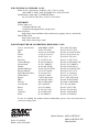
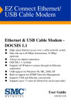
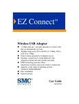
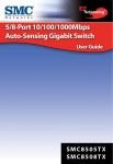
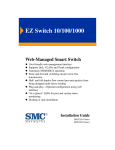
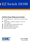
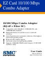
EZ Card 10/100 Mbps Combo Adapter 10/100 Mbps Combo Adapter (RJ-45 + Fiber SC) Compatible with 10BASE-T, 100BASE-TX, and 100BASE-FX standards High performance for instant access to network resources Auto-Negotiation for automatic selection of the highest speed and operating mode Remote LAN wakeup support On-board socket for optional Boot ROM Supports 100BASE-TX/FX with Category 5 UTP, STP and fiber cables User Guide SMC1255FTX-SC SMC1255FTX-SC EU EZ Card 10/100 Mbps Combo Adapter User Guide From SMC’s EZ line of low-cost workgroup LAN solutions 38 Tesla Irvine, CA 92618 Phone: (949) 679-8000 August 2002 Copyright Information furnished by SMC Networks, Inc. (SMC) is believed to be accurate and reliable. However, no responsibility is assumed by SMC for its use, nor for any infringements of patents or other rights of third parties which may result from its use. No license is granted by implication or otherwise under any patent or patent rights of SMC. SMC reserves the right to change specifications at any time without notice. Copyright © 2002 by SMC Networks, Inc. 38 Tesla Irvine, CA 92618 All rights reserved. Trademarks: SMC is a registered trademark; and EZ Card is a trademark of SMC Networks, Inc. Other product and company names are trademarks or registered trademarks of their respective holders. LIMITED WARRANTY Limited Warranty Statement: SMC Networks, Inc. (“SMC”) warrants its products to be free from defects in workmanship and materials, under normal use and service, for the applicable warranty term. All SMC products carry a standard 90-day limited warranty from the date of purchase from SMC or its Authorized Reseller. SMC may, at its own discretion, repair or replace any product not operating as warranted with a similar or functionally equivalent product, during the applicable warranty term. SMC will endeavor to repair or replace any product returned under warranty within 30 days of receipt of the product. The standard limited warranty can be upgraded to a Limited Lifetime* warranty by registering new products within 30 days of purchase from SMC or its Authorized Reseller. Registration can be accomplished via the enclosed product registration card or online via the SMC web site. Failure to register will not affect the standard limited warranty. The Limited Lifetime warranty covers a product during the Life of that Product, which is defined as the period of time during which the product is an “Active” SMC product. A product is considered to be “Active” while it is listed on the current SMC price list. As new technologies emerge, older technologies become obsolete and SMC will, at its discretion, replace an older product in its product line with one that incorporates these newer technologies. At that point, the obsolete product is discontinued and is no longer an “Active” SMC product. A list of discontinued products with their respective dates of discontinuance can be found at: http://www.smc.com/index.cfm?action=customer_service_warranty. All products that are replaced become the property of SMC. Replacement products may be either new or reconditioned. Any replaced or repaired product carries either a 30-day limited warranty or the remainder of the initial warranty, whichever is longer. SMC is not responsible for any custom software or firmware, configuration information, or memory data of Customer contained in, stored on, or integrated with any products returned to SMC pursuant to any warranty. Products returned to SMC should have any customer-installed accessory or add-on components, such as expansion modules, removed prior to returning the product for replacement. SMC is not responsible for these items if they are returned with the product. Customers must contact SMC for a Return Material Authorization number prior to returning any product to SMC. Proof of purchase may be required. Any product returned to SMC without a valid Return Material Authorization (RMA) number clearly marked on the outside of the package will be returned to customer at customer’s expense. For warranty claims within North America, please call our toll-free customer support number at (800) 762-4968. Customers are responsible for all shipping charges from their facility to SMC. SMC is responsible for return shipping charges from SMC to customer. i LIMITED WARRANTY WARRANTIES EXCLUSIVE: IF AN SMC PRODUCT DOES NOT OPERATE AS WARRANTED ABOVE, CUSTOMER’S SOLE REMEDY SHALL BE REPAIR OR REPLACEMENT OF THE PRODUCT IN QUESTION, AT SMC’S OPTION. THE FOREGOING WARRANTIES AND REMEDIES ARE EXCLUSIVE AND ARE IN LIEU OF ALL OTHER WARRANTIES OR CONDITIONS, EXPRESS OR IMPLIED, EITHER IN FACT OR BY OPERATION OF LAW, STATUTORY OR OTHERWISE, INCLUDING WARRANTIES OR CONDITIONS OF MERCHANTABILITY AND FITNESS FOR A PARTICULAR PURPOSE. SMC NEITHER ASSUMES NOR AUTHORIZES ANY OTHER PERSON TO ASSUME FOR IT ANY OTHER LIABILITY IN CONNECTION WITH THE SALE, INSTALLATION, MAINTENANCE OR USE OF ITS PRODUCTS. SMC SHALL NOT BE LIABLE UNDER THIS WARRANTY IF ITS TESTING AND EXAMINATION DISCLOSE THE ALLEGED DEFECT IN THE PRODUCT DOES NOT EXIST OR WAS CAUSED BY CUSTOMER’S OR ANY THIRD PERSON’S MISUSE, NEGLECT, IMPROPER INSTALLATION OR TESTING, UNAUTHORIZED ATTEMPTS TO REPAIR, OR ANY OTHER CAUSE BEYOND THE RANGE OF THE INTENDED USE, OR BY ACCIDENT, FIRE, LIGHTNING, OR OTHER HAZARD. LIMITATION OF LIABILITY: IN NO EVENT, WHETHER BASED IN CONTRACT OR TORT (INCLUDING NEGLIGENCE), SHALL SMC BE LIABLE FOR INCIDENTAL, CONSEQUENTIAL, INDIRECT, SPECIAL, OR PUNITIVE DAMAGES OF ANY KIND, OR FOR LOSS OF REVENUE, LOSS OF BUSINESS, OR OTHER FINANCIAL LOSS ARISING OUT OF OR IN CONNECTION WITH THE SALE, INSTALLATION, MAINTENANCE, USE, PERFORMANCE, FAILURE, OR INTERRUPTION OF ITS PRODUCTS, EVEN IF SMC OR ITS AUTHORIZED RESELLER HAS BEEN ADVISED OF THE POSSIBILITY OF SUCH DAMAGES. SOME STATES DO NOT ALLOW THE EXCLUSION OF IMPLIED WARRANTIES OR THE LIMITATION OF INCIDENTAL OR CONSEQUENTIAL DAMAGES FOR CONSUMER PRODUCTS, SO THE ABOVE LIMITATIONS AND EXCLUSIONS MAY NOT APPLY TO YOU. THIS WARRANTY GIVES YOU SPECIFIC LEGAL RIGHTS, WHICH MAY VARY FROM STATE TO STATE. NOTHING IN THIS WARRANTY SHALL BE TAKEN TO AFFECT YOUR STATUTORY RIGHTS. * SMC will provide warranty service for one year following discontinuance from the active SMC price list. Under the limited lifetime warranty, internal and external power supplies, fans, and cables are covered by a standard one-year warranty from date of purchase. SMC Networks, Inc. 38 Tesla Irvine, CA 92618 ii COMPLIANCES FCC - Class B This equipment has been tested and found to comply with the limits for a Class B digital device, pursuant to Part 15 of the FCC Rules. These limits are designed to provide reasonable protection against harmful interference in a residential installation. This equipment generates, uses and can radiate radio frequency energy and, if not installed and used in accordance with instructions, may cause harmful interference to radio communications. However, there is no guarantee that the interference will not occur in a particular installation. If this equipment does cause harmful interference to radio or television reception, which can be determined by turning the equipment off and on, the user is encouraged to try to correct the interference by one or more of the following measures: • Reorient the receiving antenna • Increase the separation between the equipment and receiver • Connect the equipment into an outlet on a circuit different from that to which the receiver is connected • Consult the dealer or an experienced radio/TV technician for help EC Conformance Declaration - Class B SMC contact for these products in Europe is: SMC Networks Europe, Edificio Conata II, Calle Fructuós Gelabert 6-8, 2o, 4a, 08970 - Sant Joan Despí, Barcelona, Spain. This information technology equipment complies with the requirements of the Low Voltage Directive 73/23/EEC and the EMC Directive 89/336/EEC, and carries the CE Mark accordingly. It conforms to the following specifications: EMC: EN55022 (1988)/CISPR-22 (1995) IEC 1000-4-2 (1995) IEC 1000-4-3 (1995) IEC 1000-4-4 (1995) IEC 1000-4-6 (1995) IEC 1000-4-11 (1995) Class B 4 kV CD, 8 kV AD 3 V/m 1.0 kV - (power line) 0.5 kV - (signal line) 3 Vrms Voltage drop iii Industry Canada - Class B This digital apparatus does not exceed the Class B limits for radio noise emissions from digital apparatus as set out in the interference-causing equipment standard entitled “Digital Apparatus”, ICES-003 of Industry Canada. Cet appareil numérique respecte les limites de bruits radioélectriques applicables aux appareils numériques de Classe B prescrites dans la norme sur le matérial brouilleur: “Appareils Numériques”, NMB-003 édictée par l’Industrie. iv TABLE CONTENTS OF About the EZ Card 10/100 Mbps Combo Adapter . . . . . . . . . . . . . . . . . . . . . . . . . . . . . . . . . . .1 LED Indicators . . . . . . . . . . . . . . . . . . . . . . . . . . . . . . . . . . . . . 1 Installing the Card . . . . . . . . . . . . . . . . . . . . . . . . . .3 Equipment Checklist . . . . . . . . . . . . . . . . . . . . . . . . . . . . . . . . 3 Hardware Installation . . . . . . . . . . . . . . . . . . . . . . . . . . . . . . . . 4 PCI Configuration . . . . . . . . . . . . . . . . . . . . . . . . . . . . . . 6 Installing and Configuring Network Drivers . . . .7 Windows 95/98/Me/2000 Installation . . . . . . . . . . . . . . . . . Optional Procedures to Modify Card Settings and Add Network Protocols . . . . . . . . . . . . . . . . . . . . . Windows NT 4.0 Installation . . . . . . . . . . . . . . . . . . . . . . . First-Time Installation . . . . . . . . . . . . . . . . . . . . . . . . Secondary Installation . . . . . . . . . . . . . . . . . . . . . . . . Windows XP Installation . . . . . . . . . . . . . . . . . . . . . . . . . . ... 7 . . . . . . . . . . 13 13 13 18 20 Testing the Network Card . . . . . . . . . . . . . . . . . . .24 Windows Windows Windows Windows 95/98/Me NT . . . . . 2000 . . . . XP . . . . . . . . . . . . . . . . . . . . . . . . . . . . . . . . . . . . . . . . . . . . . . . . . . . . . . . . . . . . . . . . . . . . . . . . . . . . . . . . . . . . . . . . . . . . . . . . . . . . . . . . . . . . . . . . . . . . . . . . . . . . . . . . . . . . . 24 24 25 26 Troubleshooting . . . . . . . . . . . . . . . . . . . . . . . . . .27 PCI Compatibility . . . . . . . . . . . . . . . . . . . Solutions for Common Problems . . . . . . . Basic Troubleshooting . . . . . . . . . . Network Card Installation Problems Network Connection Problems . . . . . . . . . . . . . . . . . . . . . . . . . . . . . . . . . . . . . . . . . . . . . . . . . . . . . . . . . . . . . . . . . . . . . . . . . . . . . . . 27 28 28 28 29 v TABLE OF CONTENTS Cables . . . . . . . . . . . . . . . . . . . . . . . . . . . . . . . . . . 30 Cable Specifications . . . . . . . . . . . . . . . . . . . . . . . . . . . . . . . . 30 Twisted-Pair Cable and Pin Assignments . . . . . . . . . . . . . . . . . 30 10BASE-T/100BASE-TX Pin Assignments . . . . . . . . . . . . . 31 Specifications . . . . . . . . . . . . . . . . . . . . . . . . . . . . 33 General Specifications . . . . . . . . . . . . . . . . . . . . . . . . . . . . . . . 33 Software Drivers . . . . . . . . . . . . . . . . . . . . . . . . . . . . . . . . . . . 34 vi ABOUT THE EZ CARD 10/ 100 MBPS COMBO ADAPTER The EZ Card 10/100 Mbps Combo Adapter is based on advanced silicon to maximize throughput and increase the efficiency of your network. It features a dual-speed, bus-master design, and supports auto-negotiation and all common networking environments. The RJ-45 connector supports auto-negotiation, so the port can configure itself automatically to run at the highest possible data-transfer rate—10 or 100 Mbps and half or full duplex—providing the link partner also supports auto-negotiation. The Wake-On-LAN (WOL) cable allows a WOL-enabled PC to be managed remotely. Software can be loaded and updated, configurations changed, data backed up, inventory checked, viruses removed, device conflicts eliminated and system crashes repaired from a remote central location. This decreases user downtime and increases overall productivity. LED Indicators The EZ Card network adapter includes at-a-glance LED indicators to monitor the port connection. Depending on the model, the LEDs are positioned on the bracket below the port, or are built 1 ABOUT THE EZ CARD 10/100 MBPS COMBO ADAPTER into the RJ-45 port. All the LED indicators are as described in the following figure and table. LED Condition Status LNK Green Indicates a valid 10BASE-T, 100BASE-TX, or 100BASE-FX link. Off Power is off or connection is invalid. ACT (T/R) Flashing Amber Indicates that the network card is transmitting or receiveing data. 100 Green Indicates a 100 Mbps connection to the network card. Off Indicates a 10 Mbps connection to the network card. Amber Indicates the network card is operating in full-duplex mode. Flashing Amber Packet collision is occurring in half-duplex mode. Off Indicates the network card is operating in half-duplex mode. FDX 2 INSTALLING THE CARD Equipment Checklist After unpacking the EZ Card, check the contents of the box to be sure you have received the following components: • EZ Card 10/100 Mbps Combo Adapter • Wake-On-LAN Cable • One Driver and Documentation CD • SMC Warranty Registration Card • User Guide Immediately inform your dealer in the event of any incorrect, missing, or damaged parts. If possible, please retain the carton and original packing materials in case there is a need to return the product. Please fill out and return the Warranty Registration Card to SMC or register on SMC’s Web site. The EZ Card is covered by a limited lifetime warranty. 3 INSTALLING THE CARD Hardware Installation 1. Switch off all computer system components, unplug the computer, and remove the computer cover. 2. Work in a static-free area and touch the computer chassis often to equalize static charges. 3. Install the network card into an available bus-mastering PCI slot. 4. Make sure the network card is completely seated so that no “gold fingers” are exposed. Figure 1. Inserting the Network Card 5. Connect the SMC1255FTX-SC directly to your switch, hub or cable/dsl modem using UTP cable (Category 3, 4 or 5 for 10BASE-T; Category 5 for 100BASE-TX). The maximum allowable length of UTP cable connections is 100 meters (328ft). When inserting an RJ-45 plug, be sure the tab on the plug clicks into position to ensure that it is properly seated. The SMC1255FTX-SC comes with an SC connector that supports 100Base-FX fiber connections using 62.5/125 or 50/ 4 HARDWARE INSTALLATION 125 micron multimode fiber optic cabling. Because SC connections are keyed, they can only be attached in one orientation. Connect one end of the fiber cable to the card’s SC connector and the other end of the cable to the fiber connector on the other device. Make certain that the device you are connecting to is specified for 100 Mbps operation. Figure 2. Connecting the SC connector 6. Replace the computer’s cover and power it on. The SMC1255FTX-SC should be automatically configured by the host computer’s BIOS. However, if you have an older computer, you may have to manually configure the computer’s BIOS settings. The RJ-45 connector supports auto-negotiation, so the port can configure itself automatically to run at the highest possible data transfer rate (10 or 100 Mbps and half or full duplex) providing the link partner also supports Auto-Negotiation. The SC fiber connector enables the SMC1255FTX-SC model to support 100 Mbps transmissions at full and half duplex over 62.5/50/125 micron multimode fiber cable. A fiber cable link operating in full-duplex mode can extend to remote sites up to 2 km (1.24 miles) away. 5 INSTALLING THE CARD 7. This model supports a Wake-On-LAN connector. The Wake-On-LAN (WOL) cable allows a WOL-enabled PC to be managed remotely. Software can be loaded and updated, configurations changed, data backed up, inventory checked, viruses removed, and device conflicts eliminated. This decreases user downtime and increases overall productivity. For using the WOL function, connect one end of the 3-pin WOL cable to connector J1 on the card, and the other end to the “5V Standby” connector on the computer’s motherboard, as shown in the following figure. (Refer to your computer’s installation manual to locate the 5V Standby connector.) Wake-On-LAN Cable J1 “ 5V Standby” Connector Figure 3. Attaching the Wake-On-LAN Cable PCI Configuration In most cases, your network card is automatically configured when you power-up your computer. In certain computers, however, you must modify your BIOS by entering your CMOS SETUP utility. For more information, refer to “PCI Compatibility” on page 27. 6 INSTALLING CONFIGURING NETWORK DRIVERS AND Windows 95/98/Me/2000 Installation You may find that the instructions here do not exactly match your version of Windows. This is because these steps and screenshots were created from Windows 98. Windows 95, Windows Millennium Edition, and Windows 2000 are very similar, but not identical, to Windows 98. Notes: 1. For Windows NT and Window XP installations, please skip to page 13 for instructions. 2. Installation processes such as these usually require the use of your original, licensed copy of Windows. Please have your Windows CD on hand BEFORE proceeding with the installation. 7 INSTALLING AND CONFIGURING NETWORK DRIVERS 1. After you have inserted the SMC1255FTX-SC in your machine, the Windows operating system will automatically recognize the adapter and prompt you for the appropriate drivers. Click the “Next” button to begin the installation. 8 WINDOWS 95/98/ME/2000 INSTALLATION 2. Insert the Driver CD and select the “Search for the best driver for your device” option and click “Next”. 9 INSTALLING AND CONFIGURING NETWORK DRIVERS 3. Clear all checkboxes except for “Specify a location:” Then press the “Browse” button and look for the drivers on your CD-ROM. (“[CD drive]:\. In most cases, this is D:\.) 4. The system should find the drivers. Now click the “Next” button to continue the installation. Note: 10 If the system could not find the drivers, click the “Back” button, and select the “Display a list of all the drivers...” option. Select “Network Adapters” from the list of devices, press “Have Disk” and once again browse to the location of the drivers. WINDOWS 95/98/ME/2000 INSTALLATION 5. Once the system has copied the SMC drivers from the CD, it may then request files from your original Windows disk. Please insert the Windows CD at this time. 6. The system will copy the files. Do NOT press “Cancel.” 11 INSTALLING AND CONFIGURING NETWORK DRIVERS 7. Once all the necessary files are copied from the Windows disk, the driver install process will be complete. Click “Finish” to exit the wizard. 8. You will then be prompted to reboot the machine. Please press “Yes.” Upon reboot, the SMC1255FTX-SC will be initialized and ready for use. 12 WINDOWS NT 4.0 INSTALLATION Optional Procedures to Modify Card Settings and Add Network Protocols • Double-click on the “My Computer,” “Control Panel,” and “Network” icons. The “Network” dialog box appears. If the correct network protocols are not installed in the “Primary Network Logon” list box, select the primary network to which you will be attaching. Click on “Add.” The “Select Network Component Type” dialog box appears. Follow the on-screen directions to select network protocols. • For peer-to-peer networks, you may wish to enable “File and Print Sharing” in the “Network” dialog box. • To modify other network card properties, select the appropriate tab or click on the “Properties” button from the “Network” dialog box and modify properties as desired. Windows NT 4.0 Installation First-Time Installation If you have already installed a network card, configured Windows NT Networking, or configured a network driver, refer to the procedure titled “Secondary Installation.” 1. Windows NT is not a Plug-and-Play operating system. You will need to manually install the adapter. 2. Shut down your PC, install the SMC network card, and attach the network cable. Restart Windows NT. 3. Double-click on the “My Computer,” “Control Panel,” and “Network” icons. The “Network Configuration” window appears, prompting you to install Windows NT Networking. 13 INSTALLING AND CONFIGURING NETWORK DRIVERS Select the “Wired to the network” option and click the “Next” button to continue. 4. When prompted to “Search for a Network Adapter,” click on “Select from List.” 14 WINDOWS NT 4.0 INSTALLATION 5. When prompted to “Select a Network Adapter,” click on “Have Disk.” Insert the installation CD and enter “D:\winnt.” (“[CD drive]:\. In most cases, this is D:\.) 15 INSTALLING AND CONFIGURING NETWORK DRIVERS 6. Select the SMC1255FTX-SC adapter, and click on “Next.” 7. Select network protocols when prompted and click “Next.” 16 WINDOWS NT 4.0 INSTALLATION Note: To complete a TCP/IP installation, you will need to know your IP Address and Subnet Mask. For further information, contact your network administrator or Internet service provider. 8. Click on “Next” and then “Next” again when prompted to “Install Network Components.” When prompted for Windows NT files, type the path to your Windows NT files on CD-ROM (e.g., D:\i386), or change the path to those files on your hard drive, and click on “OK.” 9. You are presented with the “Network Card Setup” window where you can specify the network card data rate. “AUTONEGOTIATE” is the recommended setting for the network card. Select “Continue” after verifying the network card settings. 10. Click on “Next” and then “Next” again when prompted to “Start the Network.” 17 INSTALLING AND CONFIGURING NETWORK DRIVERS 11. Enter the “Workgroup” or “Domain” names (optional) when prompted and click on “Next.” 12. Select “Finish” when prompted, and click on “Yes” when prompted to reboot. For Further Customization You can modify card settings via the “Network” applet. Install additional protocols and network components by selecting the appropriate folder (e.g., Customizing Protocols, Services, Identification, or Bindings). Secondary Installation Follow this procedure if you have already installed another network card, configured Windows NT Networking, or loaded another driver. 1. Install the SMC network card (if not already installed), attach the network cable, and boot Windows NT. 2. Double-click on the “My Computer,” “Control Panel,” and “Network” icons. From the “Network” window, select the Adapter tab. 3. Do not select any of the network cards listed. Select “Add.” 4. You are presented with the “Select Network Adapter” window. Click on “Have Disk.” 5. You are presented with the “Insert Disk” window. Specify the path to the NT directory of the installation CD (e.g., D:\winnt) and click on “OK.” 6. Select the SMC1255FTX-SC adapter, and click on “Next.” 7. You are presented with the “Network Card Setup” window where you can specify the network card data rate. 18 WINDOWS NT 4.0 INSTALLATION “AUTONEGOTIATE” is the recommended setting for the network card. Select “OK” after verifying the network card settings. 8. You are presented with the “Network” window where the SMC network card is now listed as an installed adapter. At this point you can select “Close” to exit the Network applet and follow the prompts to restart Windows NT. 9. Select “Yes” when prompted to reboot for the changes to take effect. For Further Customization You can modify card settings via the “Network” applet. Install additional protocols and network components by selecting the appropriate folder (e.g., Customizing Protocols, Services, Identification, or Bindings). 19 INSTALLING AND CONFIGURING NETWORK DRIVERS Windows XP Installation 1. After you have inserted the SMC1255FTX-SC in your machine and turned it back on, the OS will automatically recognize the adapter and prompt you for the appropriate drivers. Click the “Next” button to begin the installation. 20 WINDOWS XP INSTALLATION 2. Insert the Driver CD and check the “Include this location in the search” option. Make sure the “Search removable media” option is not checked. Click “Browse” and find the location of the drivers. This should be “[CD drive]:\.” (In most cases, this is D:\.) Then click “Next >.” 21 INSTALLING AND CONFIGURING NETWORK DRIVERS 3. Click “Continue Anyway” to continue the installation. Please do NOT click “STOP Installation” as this will cancel the driver wizard and the card will not be installed properly. 22 WINDOWS XP INSTALLATION 4. This process will be completed once the drivers are copied to the hard drive and installed. Please click “Finish” to exit the wizard. After clicking “Finish,” you will see the following message in your system tray: Latest Drivers Driver updates can be downloaded from SMC’s web site (see the back cover of this guide). 23 TESTING THE NETWORK CARD This section will help you verify that the adapter is installed properly. Windows 95/98/Me 1. Right-click the My Computer icon on your desktop and click “Properties.” 2. Then go to the “Device Manager” tab and open the “Network adapters” section. You should see your SMC1255FTX-SC in this menu. Highlight it and click “Properties.” 3. The Device Status shows that the “This device is working properly.” If there are any error messages displayed here, you will need to click the SMC adapter and click “Remove.” Then reboot the machine and go through the installation process again. Windows NT 1. Double-click on the “My Computer,” “Control Panel,” and “Network” icons. From the “Network” window, select the Adapter tab. 2. Click on the “Properties” button to verify that the SMC1255FTX-SC adapter is listed in the “Adapters” section. 3. Click “Start,” click “Run” and type “eventvwr.” This will bring up the entire System Log in the Event Viewer. Make sure that there are no error messages regarding the initialization of the SMC adapter. 24 WINDOWS 2000 4. Open your NT diagnostics utility and make sure that the SMC adapter is listed under the “Resources” tab. This will verify that the adapter was successfully initialized using the IRQ specified in this section. Windows 2000 1. Right-click the My Computer icon on your desktop and click “Properties.” 2. Then go to the Hardware tab and click “Device Manager.” Open the “Network adapters” section. You should see your SMC1255FTX-SC in this menu. Right-click your adapter and click “Properties.” 3. The Device Status shows that the “This device is working properly.” If there are any error messages displayed here, you will need to right-click the SMC adapter and click “Uninstall.” Then reboot the machine and go through the installation process again. 25 TESTING THE NETWORK CARD Windows XP 1. Click “Start” and click “Control Panel.” Then click the “Performance and Maintenance” icon and select “System.” 2. Then go to the Hardware tab and click “Device Manager.” Open the “Network adapters” section. You should see your SMC1255FTX-SC in this menu. Right-click the adapter and click “Properties.” 3. The Device Status shows that “This device is working properly.” If there are any error messages displayed here, you will need to right-click the SMC adapter and click “Uninstall.” Then reboot the machine and go through the installation process again. 26 TROUBLESHOOTING PCI Compatibility Early PCI BIOS versions do not properly support the PCI specification and may “hang” when a network card driver tries to load. If this occurs, make sure your BIOS correctly supports the PCI Local Bus Specification (v2.0 or later) and upgrade your computer BIOS to the latest version. Some PCI computers are not self-configuring and require you to perform some or all of the following functions by changing motherboard jumpers and/or configuring the BIOS setup program: • Verify that the PCI slot is an enabled busmaster slot and not a slave PCI slot. The EZ Card must be installed in a PCI busmaster slot. In some computers the PCI slot must be configured to enable bus mastering. Refer to your PC’s manual and check the PCI BIOS setup program to be sure the PCI slot is an enabled busmaster slot. • In some computers, you may be required to disable Plug ‘n Play (PnP) in the BIOS setup program if resources are not properly assigned between the network card and other installed cards. • Some computers may require you to reserve interrupts and memory addresses for installed ISA cards to prevent PCI cards from using the same settings. Refer to your PC’s manual and check the PCI BIOS setup program configuration options for ISA cards. 27 TROUBLESHOOTING Solutions for Common Problems Basic Troubleshooting Network problems are often caused by cabling errors, conflicts with other devices installed in the same computer, or software that has been configured incorrectly. If you encounter a problem, use the checklists and guidelines in this section to try and identify the problem before contacting SMC Technical Support. Network Card Installation Problems If your computer cannot find the EZ Card or the network driver does not install correctly, check the following items. 28 • Make sure the card is securely seated in the PCI slot. Check for any hardware problems, such as physical damage to the card’s edge connector. • Try the card in another PCI busmaster slot. If all fails, test with another EZ Card that is known to operate correctly. • Check for resource conflict in the PCI configuration. Refer to the section “PCI Compatibility” in this chapter. • If there are other network cards in the computer, they may be causing conflict. Remove all other cards from the computer and test the EZ Card separately. • Check for a defective computer or PCI bus by trying the network card in another computer that is known to operate correctly. • Make sure your computer is using the latest BIOS available. SOLUTIONS FOR COMMON PROBLEMS Network Connection Problems There may be a network connection problem if the Link LED on the card’s bracket does not light, or if you cannot access any network resources from the computer. Check the following items. • Make sure the cable is within IEEE 802.3 Ethernet, or IEEE802.3u Fast Ethernet standards for the type of network you are using. Also, make sure cable lengths are within the requirements specified in “Cables” on page 30. • Inspect all network cables and connections. Make sure the network cable is securely attached to the card’s connector. • Make sure the correct network card driver is installed for your operating system. If necessary, try reinstalling the driver. • Make sure the computer and other network devices are receiving power. If you suspect a power outlet to be faulty, plug another device into it to verify that it is working. • If the the network card’s speed or duplex mode has been configured manually, check that it matches that of the attached network device port. Note that it is recommended to set the card to auto-negotiation when installing the network driver. • The port on the network device that the card is attached to may be defective. Try using another port on the device. • If you cannot access a Windows service on the network, check that you have enabled and configured the service correctly. If you cannot connect to a particular server, be sure that you have access rights and a valid ID and password. • If you cannot access the Internet, be sure you have configured your system for TCP/IP. 29 CABLES Cable Specifications Cable Types and Specifications Cable Type Max. Length Connector 10BASE-T Cat. 3, 4, 5 100-ohm UTP 100 m (328 ft.) RJ-45 100BASE-TX Cat. 5 100-ohm UTP 100 m (328 ft.) RJ-45 100BASE-FX 50/125 or 62.5/125 micron core multimode fiber Half duplex 412 m (1,351.4 ft.) SC Full duplex 2 km (1.24 miles) SC Twisted-Pair Cable and Pin Assignments Caution: DO-NOT plug a phone jack connector into any RJ-45 port. Use only twisted-pair cables with RJ-45 connectors that conform with FCC standards. For 10BASE-T/100BASE-TX connections, a twisted-pair cable must have two pairs of wires. Each wire pair is identified by two different colors. For example, one wire might be red and the other, red with white stripes. Also, an RJ-45 connector must be attached to both ends of the cable. Caution: Each wire pair must be attached to the RJ-45 connectors in a specific orientation. 30 TWISTED-PAIR CABLE AND PIN ASSIGNMENTS The following figure illustrates how the pins on the RJ-45 connector are numbered. Be sure to hold the connectors in the same orientation when attaching the wires to the pins. Figure 4. RJ-45 Connector Pin Numbers 10BASE-T/100BASE-TX Pin Assignments With 10BASE-T/100BASE-TX cable, pins 1 and 2 are used for transmitting data, and pins 3 and 6 for receiving data. The “+” and “-” signs in the tables below are used to represent the polarity of the wires that make up each wire pair. RJ-45 Pin Assignments Pin Number Assignment 1 Tx+ 2 Tx- 3 Rx+ 6 Rx- 31 CABLES Straight-Through Wiring If the twisted-pair cable is to join two ports and only one of the ports has an internal crossover, the two pairs of wires must be straight-through. Straight-Through RJ-45 Pin Assignments End 1 End 2 1(Tx+) 1(Tx+) 2(Tx-) 2(Tx-) 3(Rx+) 3(Rx+) 6(Rx-) 6(Rx-) Crossover Wiring If the twisted-pair cable is to join two ports and either both ports are labeled with an “x” (MDI-X) or neither port is labeled with an “x” (MDI), a crossover must be implemented in the wiring. Crossover RJ-45 Pin Assignments 32 End 1 End 2 1(Tx+) 3(Rx+) 2(Tx-) 6(Rx-) 3(Rx+) 1(Tx+) 6(Rx-) 2(Tx-) SPECIFICATIONS General Specifications Bus Interface PCI Interrupt Channel Network Card Type Connectors Network Interface Cable Size (without bracket) Weight Operating Voltage Temperature Humidity Standards Compliances Warranty 32-bit PCI Bus Master INTA 10BASE-T/100BASE-TX, 100BASE-FX RJ-45 for 10BASE-T/100BASE-TX SC connector for 100BASE-FX 3-pin Wake-On-LAN cable connector 10BASE-T: UTP cable; Categories 3, 4,or 5 100BASE-TX: UTP cable; Category 5 100BASE-FX: 50/125 or 62.5/125 micron multimode fiber cable 9.1 x 12.0 cm (3.605 x 4.750 in.) 70 gm (2.52 oz.) RJ-45: +5 VDC @ 450 mA (typical) Fiber: +5 VDC @ 400 mA (typical) +12 VDC @ 1.2 mA Operating: 0 to 50 °C (32 to 122 °F) Storage: -40 to 70 °C (-40 to 158 °F) Operating: 10% to 90% Storage: 5% to 95% IEEE 802.3 Ethernet IEEE 802.3u Fast Ethernet PCI v2.1 and v2.2 CE Mark FCC Class B Limited lifetime 33 SPECIFICATIONS Software Drivers ODI Drivers NDIS Drivers Unix Drivers 34 NetWare Server 4.11, 5.0 and 5.1 Windows 95 OSR2.1 or above version Windows 98 Windows Me Windows NT 4.0 Windows 2000 Windows XP Linux 2.2x, 2.4 or later FOR TECHNICAL SUPPORT, CALL: From U.S.A. and Canada (24 hours a day, 7 days a week) (800) SMC-4-YOU; (949) 679-8000; Fax: (949) 679-1481 From Europe (8:00 AM - 5:30 PM UK Time) 44 (0) 118 974 8700; Fax: 44 (0) 118 974 8701 INTERNET E-mail addresses: [email protected] [email protected] Driver updates: http://www.smc.com/index.cfm?action=tech_support_drivers_downloads World Wide Web: http://www.smc.com/ http://www.smc-europe.com/ FOR LITERATURE OR ADVERTISING RESPONSE, CALL: U.S.A. and Canada: Spain: UK: France: Italy: Benelux: Central Europe: Switzerland: Nordic: Northern Europe: Eastern Europe: Sub Saharian Africa: North Africa: Russia: PRC: Taiwan: Asia Pacific: Korea: Japan: Australia: India: (800) SMC-4-YOU; 34-93-477-4935; 44 (0) 118 974 8700; 33 (0) 41 38 32 32; 39 02 739 12 33; 31 33 455 72 88; 49 (0) 89 92861-0; 41 (0) 1 9409971; 46 (0) 868 70700; 44 (0) 118 974 8700; 34 -93-477-4920; 27-11 314 1133; 34 93 477 4920; 7 (095) 290 29 96; 86-10-6235-4958; 886-2-2659-9669; (65) 238 6556; 82-2-553-0860; 81-45-224-2332; 61-2-9416-0437; 91-22-8204437; Fax (949) 679-1481 Fax 34-93-477-3774 Fax 44 (0) 118 974 8701 Fax 33 (0) 41 38 01 58 Fax 39 02 739 14 17 Fax 31 33 455 73 30 Fax 49 (0) 89 92861-230 Fax 41 (0) 1 9409972 Fax 46 (0) 887 62 62 Fax 44 (0) 118 974 8701 Fax 34 93 477 3774 Fax 27-11 314 9133 Fax 34 93 477 3774 Fax 7 (095) 290 29 96 Fax 86-10-6235-4962 Fax 886-2-2659-9666 Fax (65) 238 6466 Fax 82-2-553-7202 Fax 81-45-224-2331 Fax 61-2-9416-0474 Fax 91-22-8204443 If you are looking for further contact information, please visit www.smc.com or www.smc-europe.com. 38 Tesla Irvine, CA 92618 Phone: (949) 679-8000 Model Number: SMC1255FTX-SC SMC1255FTX-SC EU E082002-R01