1
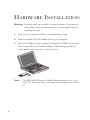
SMC2635W
EZ Connect 2.4GHz 11 Mbps
Wireless Cardbus Adapter
User Guide
The easy way to make all your network connections
38 Tesla
Irvine, CA 92618
Phone: (949) 679-8000
April 2003
Revision Number: F1.0
Pub No: 150000021200E R01
Copyright
Information furnished by SMC Networks, Inc. (SMC) is believed to be accurate and reliable.
However, no responsibility is assumed by SMC for its use, nor for any infringements of patents
or other rights of third parties which may result from its use. No license is granted by
implication or otherwise under any patent or patent rights of SMC. SMC reserves the right to
change specifications at any time without notice.
Copyright © 2003 by
SMC Networks, Inc.
38 Tesla
Irvine, CA 92618
All rights reserved. Printed in Taiwan
Trademarks:
SMC is a registered trademark; and EZ Connect is a trademark of SMC Networks, Inc. Other
product and company names are trademarks or registered trademarks of their respective
holders.
COMPLIANCES
Federal Communication Commission Interference
Statement
This equipment has been tested and found to comply with the limits for a Class B
digital device, pursuant to Part 15 of the FCC Rules. These limits are designed to
provide reasonable protection against harmful interference in a residential
installation. This equipment generates, uses and can radiate radio frequency energy
and, if not installed and used in accordance with the instructions, may cause
harmful interference to radio communications. However, there is no guarantee that
interference will not occur in a particular installation. If this equipment does cause
harmful interference to radio or television reception, which can be determined by
turning the equipment off and on, the user is encouraged to try to correct the
interference by one of the following measures:
• Reorient or relocate the receiving antenna
• Increase the separation between the equipment and receiver
• Connect the equipment into an outlet on a circuit different from that to which the
receiver is connected
• Consult the dealer or an experienced radio/TV technician for help
FCC Caution: To assure continued compliance, (example - use only shielded
interface cables when connecting to computer or peripheral devices) any changes
or modifications not expressly approved by the party responsible for compliance
could void the user's authority to operate this equipment. This device complies
with Part 15 of the FCC Rules. Operation is subject to the following two conditions:
(1) This device may not cause harmful interference, and (2) this device must accept
any interference received, including interference that may cause undesired
operation.
IMPORTANT NOTE:
FCC Radiation Exposure Statement:
This equipment complies with FCC radiation exposure limits set forth for an
uncontrolled environment. This transmitter must not be co-located or operating in
conjunction with any other antenna or transmitter.
i
COMPLIANCES
Industry Canada - Class B
This digital apparatus does not exceed the Class B limits for radio noise emissions
from digital apparatus as set out in the interference-causing equipment standard
entitled “Digital Apparatus,” ICES-003 of Industry Canada.
Cet appareil numérique respecte les limites de bruits radioélectriques applicables
aux appareils numériques de Classe B prescrites dans la norme sur le matérial
brouilleur: “Appareils Numériques,” NMB-003 édictée par l’Industrie.
EC Conformance Declaration - Class B
SMC contact for these products in Europe is:
SMC Networks Europe,
Edificio Conata II,
Calle Fructuós Gelabert 6-8, 2o, 4a,
08970 - Sant Joan Despí,
Barcelona, Spain.
This information technology equipment complies with the requirements of the
Council Directive 89/336/EEC on the Approximation of the laws of the Member
States relating to Electromagnetic Compatibility and 73/23/EEC for electrical
equipment used within certain voltage limits and the Amendment Directive 93/68/
EEC. For the evaluation of the compliance with these Directives, the following
standards were applied:
RFI Emission:
• Limit class B according to EN 55022:1998, IEC 60601-1-2 (EMC,
medical)
• Limit class B for harmonic current emission according to
EN 61000-3-2/1995
• Limitation of voltage fluctuation and flicker in low-voltage supply
system according to EN 61000-3-3/1995
Immunity:
• Product family standard according to EN 55024:1998
• Electrostatic Discharge according to EN 61000-4-2:1995
(Contact Discharge: ±4 kV, Air Discharge: ±8 kV)
• Radio-frequency electromagnetic field according to
EN 61000-4-3:1996 (80 - 1000 MHz with 1 kHz AM 80%
Modulation: 3 V/m)
• Electrical fast transient/burst according to EN 61000-4-4:1995
(AC/DC power supply: ±1 kV, Data/Signal lines: ±0.5 kV)
• Surge immunity test according to EN 61000-4-5:1995
(AC/DC Line to Line: ±1 kV, AC/DC Line to Earth: ±2 kV)
ii
COMPLIANCES
• Immunity to conducted disturbances, Induced by
radio-frequency fields: EN 61000-4-6:1996 (0.15 - 80 MHz with
1 kHz AM 80% Modulation: 3 V/m)
• Power frequency magnetic field immunity test according to
EN 61000-4-8:1993 (1 A/m at frequency 50 Hz)
• Voltage dips, short interruptions and voltage variations immunity
test according to EN 61000-4-11:1994 (>95% Reduction @10 ms,
30% Reduction @500 ms, >95% Reduction @5000 ms)
LVD:
• EN 60950 (A1/1992; A2/1993; A3/1993; A4/1995; A11/1997)
MDD:
• IEC 60601-1
Safety Compliance
Wichtige Sicherheitshinweise (Germany)
1. Bitte lesen Sie diese Hinweise sorgfältig durch.
2. Heben Sie diese Anleitung für den späteren Gebrauch auf.
3. Vor jedem Reinigen ist das Gerät vom Stromnetz zu trennen. Verwenden Sie
keine Flüssigoder Aerosolreiniger. Am besten eignet sich ein angefeuchtetes
Tuch zur Reinigung.
4. Die Netzanschlu ßsteckdose soll nahe dem Gerät angebracht und leicht
zugänglich sein.
5. Das Gerät ist vor Feuchtigkeit zu schützen.
6. Bei der Aufstellung des Gerätes ist auf sicheren Stand zu achten. Ein Kippen
oder Fallen könnte Beschädigungen hervorrufen.
7. Die Belüftungsöffnungen dienen der Luftzirkulation, die das Gerät vor
Überhitzung schützt. Sorgen Sie dafür, daß diese Öffnungen nicht abgedeckt
werden.
8. Beachten Sie beim Anschluß an das Stromnetz die Anschlußwerte.
9. Verlegen Sie die Netzanschlußleitung so, daß niemand darüber fallen kann. Es
sollte auch nichts auf der Leitung abgestellt werden.
10. Alle Hinweise und Warnungen, die sich am Gerät befinden, sind zu beachten.
11. Wird das Gerät über einen längeren Zeitraum nicht benutzt, sollten Sie es vom
Stromnetz trennen. Somit wird im Falle einer Überspannung eine Beschädigung
vermieden.
12. Durch die Lüftungsöffnungen dürfen niemals Gegenstände oder Flüssigkeiten in
das Gerät gelangen. Dies könnte einen Brand bzw. elektrischen Schlag
auslösen.
13. Öffnen sie niemals das Gerät. Das Gerät darf aus Gründen der elektrischen
Sicherheit nur von authorisiertem Servicepersonal geöffnet werden.
iii
COMPLIANCES
14. Wenn folgende Situationen auftreten ist das Gerät vom Stromnetz zu trennen
und von einer qualifizierten Servicestelle zu überprüfen:
a. Netzkabel oder Netzstecker sind beschädigt.
b. Flüssigkeit ist in das Gerät eingedrungen.
c. Das Gerät war Feuchtigkeit ausgesetzt.
d. Wenn das Gerät nicht der Bedienungsanleitung entsprechend funktioniert
oder Sie mit Hilfe dieser Anleitung keine Verbesserung erzielen.
e. Das Gerät ist gefallen und/oder das Gehäuse ist beschädigt.
f. Wenn das Gerät deutliche Anzeichen eines Defektes aufweist.
15. Stellen Sie sicher, daß die Stromversorgung dieses Gerätes nach der EN 60950
geprüft ist. Ausgangswerte der Stromversorgung sollten die Werte von AC
7,5-8V, 50-60Hz nicht über oder unterschreiten sowie den minimalen Strom von
1A nicht unterschreiten.
Der arbeitsplatzbezogene Schalldruckpegel nach DIN 45 635 Teil 1000 beträgt
70dB(A) oder weniger.
iv
TABLE OF CONTENTS
EZ Connect™ Wireless Cardbus Adapter . . . . . . . . . . . . . . . 1
Features . . . . . . . . . . . . . . . . . . . . . . . . . . . . . . . . . . . . . . . . . . . . . . . . . . . . . 1
Applications . . . . . . . . . . . . . . . . . . . . . . . . . . . . . . . . . . . . . . . . . . . . . . . . . 2
System Requirements . . . . . . . . . . . . . . . . . . . . . . . . . . . . . . . . . . . . . . . . . . 3
Package Checklist . . . . . . . . . . . . . . . . . . . . . . . . . . . . . . . . . . . . . . . . . . . . . 4
Hardware Description . . . . . . . . . . . . . . . . . . . . . . . . . . . . . . . 5
LED Indicator . . . . . . . . . . . . . . . . . . . . . . . . . . . . . . . . . . . . . . . . . . . . . . . 5
Hardware Installation . . . . . . . . . . . . . . . . . . . . . . . . . . . . . . . 6
Driver Installation . . . . . . . . . . . . . . . . . . . . . . . . . . . . . . . . . . 8
Windows 98/Me/2000/XP
Driver and Utility Installation . . . . . . . . . . . . . . . . . . . . . . . . . . . . . . . 8
Utility Installation . . . . . . . . . . . . . . . . . . . . . . . . . . . . . . . . . 12
Utility Configuration . . . . . . . . . . . . . . . . . . . . . . . . . . . . . . . 13
The Wireless Utility in Windows, 98SE, Me, 2000 and XP . . . . . . . . . . 13
Quick-Launch Icon . . . . . . . . . . . . . . . . . . . . . . . . . . . . . . . . . . . . . 13
Configuration . . . . . . . . . . . . . . . . . . . . . . . . . . . . . . . . . . . . . . . . . 15
Link information . . . . . . . . . . . . . . . . . . . . . . . . . . . . . . . . . . . . . . . 18
IP Information . . . . . . . . . . . . . . . . . . . . . . . . . . . . . . . . . . . . . . . . 19
Site Survey . . . . . . . . . . . . . . . . . . . . . . . . . . . . . . . . . . . . . . . . . . . . 20
Version Information . . . . . . . . . . . . . . . . . . . . . . . . . . . . . . . . . . . . 21
Network Configuration and Planning . . . . . . . . . . . . . . . . . . 23
Network Topologies . . . . . . . . . . . . . . . . . . . . . . . . . . . . . . . . . . . . . . . . . 23
Ad Hoc Wireless LAN . . . . . . . . . . . . . . . . . . . . . . . . . . . . . . . . . . 23
Infrastructure Wireless LAN . . . . . . . . . . . . . . . . . . . . . . . . . . . . . 24
Setting the Communication Domain . . . . . . . . . . . . . . . . . . . . . . . . . . . . . 25
Stationary Wireless PCs . . . . . . . . . . . . . . . . . . . . . . . . . . . . . . . . . 25
Roaming Wireless PCs . . . . . . . . . . . . . . . . . . . . . . . . . . . . . . . . . . 25
v
TABLE OF CONTENTS
Troubleshooting . . . . . . . . . . . . . . . . . . . . . . . . . . . . . . . . . . .27
Adapter Installation Problems . . . . . . . . . . . . . . . . . . . . . . . . . . . . . . . . . . 27
Network Connection Problems . . . . . . . . . . . . . . . . . . . . . . . . . . . . . . . . . 28
SMC Networks 802.11b Wireless Product Maximum Distance
Table . . . . . . . . . . . . . . . . . . . . . . . . . . . . . . . . . . . . . . . . . . 30
Specifications . . . . . . . . . . . . . . . . . . . . . . . . . . . . . . . . . . . . . .31
General Specifications . . . . . . . . . . . . . . . . . . . . . . . . . . . . . . . . . . . . . . . . 31
Software Drivers . . . . . . . . . . . . . . . . . . . . . . . . . . . . . . . . . . . . . . . . . . . . 32
Terminology . . . . . . . . . . . . . . . . . . . . . . . . . . . . . . . . . . . . . .33
vi
EZ CONNECT™
WIRELESS CARDBUS
ADAPTER
SMC’s EZ Connect Wireless Cardbus Adapter (SMC2635W) is an
11 Mbps wireless network adapter that seamlessly integrates with existing
Ethernet networks to support applications such as mobile users or
temporary conferences. This solution offers a high data rate and reliable
wireless connectivity with considerable cost savings over wired LANs
(which include long-term maintenance overhead for cabling). Just install
enough wireless access points to cover your network area, plug wireless
cards into your notebooks, and start networking.
Using this card in conjunction with SMC 2.4 GHz wireless access points,
you can create an instant network that integrates seamlessly with Ethernet
LANs. Moreover, moving or expanding your network is as easy as moving
or installing additional access points – no wires!
Features
•
1, 2, 5.5 and 11 Mbps data rate
•
Wireless connection without the hassles and cost of cabling
•
Greater flexibility to locate or move networked PCs
•
Integrates with or replaces wired LANs at dramatically lower cost than
wired alternatives
•
Seamless connectivity to wired Ethernet LANs augments existing
networks quickly and easily
1
EZ CONNECT™ W IRELESS CARDBUS ADAPTER
•
Easy installation
•
Working range up to 160 m (528 ft) at 11 Mbps, up to 350 m (1155 ft)
at 1 Mbps (indoor communication)
•
Direct Sequence Spread-Spectrum (DSSS) technology provides
robust, interference-resistant and secure wireless connection
•
Supports a wide range of systems (Windows 98/Me/2000/XP)
•
Plug-and-Play
•
Provides a user-friendly interface for configuration
•
Enhances your network security with 64/128-bit WEP encryption
•
802.1x currently available under Windows 2000/XP
•
Wi-Fi Protected Access (WPA) available in second quarter of 2003
•
Built-in antenna
Applications
EZ Connect wireless products offer fast, reliable, cost-effective network
access for wireless clients in applications such as:
2
•
Remote access to corporate network information
E-mail, file transfer, and terminal emulation
•
Difficult-to-wire environments
Historic or old buildings, asbestos installations, and open areas where
wiring is difficult to employ
•
Frequently changing environments
Retailers, manufacturers, and banks who frequently rearrange the
workplace and change location
SYSTEM REQUIREMENTS
•
Temporary LANs for special projects or peak time
Trade shows, exhibitions, and construction sites that need to setup for
a short time period. Retailers, airline, and shipping companies who
need additional workstations for peak periods. Auditors who require
workgroups at customer sites
•
Access to databases for mobile workers
Doctors, nurses, retailers, white-collar workers who need access to
databases while being mobile in a hospital, retail store, office, campus
etc
•
SOHO users
SOHO (Small Office Home Office) users who need quick and easy
installation of a small computer network
System Requirements
Before you install the EZ Connect Wireless Cardbus Adapter, check your
system for the following requirements:
•
A computer with a CardBus slot
•
Windows 98SE/Me/2000/XP (Prepare the Windows installation
CD-ROM for use during installation.)
•
A minimum of 1500 Kbytes of free disk space for installing the driver
and utility program
•
Another IEEE 802.11b compliant device installed in your network,
such as an SMC Wireless Access Point, or another PC with a wireless
adapter
3
EZ CONNECT™ W IRELESS CARDBUS ADAPTER
Package Checklist
The EZ Connect Wireless Cardbus Adapter package includes:
•
1 Wireless Cardbus Adapter (SMC2635W)
•
1 SMC2635W EZ Installation Wizard & Documentation CD
•
This User Guide
Please register this product and upgrade the product warranty at
www.smc.com
Please inform your dealer if there are any incorrect, missing, or damaged
parts. If possible, retain the carton, including the original packing materials.
Use them again to repack the product if there is a need to return it for
repair.
4
HARDWARE DESCRIPTION
The EZ Connect Wireless Cardbus Adapter supports 1, 2, 5.5 and 11
Mbps half-duplex connections to Ethernet networks. This card is fully
compliant with 2.4 GHz DSSS CSMA/CA wireless networking as defined
in IEEE 802.11b. It can be installed in any notebook with a CardBus slot.
Support is currently provided for Windows 98SE/Me/2000/XP.
LED Indicator
The EZ Connect Wireless Cardbus Adapter includes one status LED
indicator, as described in the following figure and table.
LED
Status
Description
PWR/ACT
On Green
Card is receiving power.
Flashing
Data is being transmitted and received
between the card and the access point..
5
HARDWARE INSTALLATION
Warning: Network cards are sensitive to static electricity. To protect the
card, always touch the metal chassis of your computer before
handling the card.
1. Turn on your computer and boot your operating system.
2. Find an available Type II CardBus slot in your computer.
3. With the CardBus’s 68-pin connector facing the CardBus slot and the
“EZ Connect Wireless Cardbus Adapter” label facing up, slide the
card completely into the slot as shown below.
Note:
6
The SMC2635W Wireless Cardbus Adapter allows you to “hot
swap” PC Cards any time, even when your computer is powered
on.
HARDWARE INSTALLATION
4. For Windows 98SE/Me/2000, PCMCIA card and socket services
compliant with revision 2.10 of the PCMCIA specification are
required.
5. Install the appropriate network driver for your operating system.
Drivers can be found on the SMC2635W EZ Installation Wizard &
Documentation CD. See “Driver and Utility Installation” on the next
page for more information.
6. Install the Utility program for your Wireless Cardbus Adapter. The
SETUP.EXE file of the utiltiy program can be found on the CD.
7
DRIVER AND UTILITY
INSTALLATION
The installation CD labeled “SMC2635W EZ Installation Wizard &
Documentation CD,” that comes with the package contains all the
software drivers available for the EZ Connect Wireless Cardbus Adapter.
Any new or updated drivers can be downloaded from SMC’s Web site at:
http://www.smc.com
Note:
Check the SMC Web site for more support options. You can
access the online support options at:
http://www.smc.com/index.cfm?action=tech_support_support_tools
You may find that the instructions here do not exactly match your version
of Windows. This is because these steps and screenshots were created
from Windows 2000. Windows Millennium Edition, Windows 98SE and
Windows XP are very similar, but not identical, to Windows 2000.
8
DRIVER AND UTILITY INSTALLATION
1. Insert EZ Installation Wizard CD into the CD-ROM drive and click
Install Driver/Utility when the installation screen appears.
2. Click Install Driver/Utility.
3. The Choose Setup Language dialog box will now appear.
9
DRIVER AND UTILITY INSTALLATION
4. Select the appropriate language and click OK.
5. The auto-run program will display the InstallShield Wizard.
6. Select Easy and follow the on-screen instructions to complete the
installation.
7. The Country Select dialog box will appear.
8. Select the appropriate country.
10
DRIVER AND UTILITY INSTALLATION
9. Click Finish to complete the setup.
10. The Configuration screen for the SMC2635W will now appear. Go
to“Configuration” on page 14 to continue.
11
UTILITY CONFIGURATION
The Wireless Utility in Windows, 98SE, Me, 2000
and XP
Note that the screen shots below were taken from Windows XP and will
not look exactly the same in all operating systems. The functions, however,
are the same.
Once the installation is complete, the configuration utility can be accessed
from the Start menu, as shown below.
Quick-Launch Icon
When the utility program is running, there will be a quick launch icon in
the lower right-hand corner of the task bar. If the icon is GREEN, you
have a good connection. If it shows RED, you may need to check the
access point (e.g., an SMC Wireless Access Point) and place it in a higher
position, or move closer to the access point that you wish to connect to.
12
THE W IRELESS UTILITY IN W INDOWS, 98, ME, 2000 AND XP
Double-clicking the quick launch icon will open the EZ Connect Wireless
Cardbus Adapter Utility program, providing quick access to the adapter
settings.
The configuration utility includes the following tools:
Configuration – Allows you to monitor network status and configure
wireless adapter parameters.
Link Information– Shows wireless adapter statistics.
IP Information– Provides WEP security control.
Site Survey – Scans/Shows all the access points in range.
Version Information – Shows the version information.
At the bottom of each screen there are three boxes that can be selected:
•
Radio On/Radio Off – This allows you to turn on/off the
transmission/reception of the Cardbus.
•
Help – Click here to display the help file.
•
Exit – This closes the Configuration Utility dialogue box.
13
UTILITY CONFIGURATION
Configuration
When you start the Wireless Cardbus Adapter utility, the Configuration
screen for the SMC2635W is shown as in the figure below.
Select Profile – You can specify a profile name for a specific
configuration of parameters.
New – You can set up a new profile by clicking New.
Save – To save a new profile after configuring the settings, click Save.
Delete – To delete a profile, select the profile from the drop-down menu
in Select Profile, then click Delete.
SSID – Input an SSID string for the wireless network to which you want
to connect (ANY is the default setting). To roam among multiple access
points with different BSSIDs, set the SSID to ANY to allow connection to
any access point.
14
THE W IRELESS UTILITY IN W INDOWS, 98, ME, 2000 AND XP
Channel – If you are setting up an ad hoc wireless LAN (See “Network
Topologies” on page 21.), set the channel number to the same radio
channel as that used by the other wireless clients in your group. However,
if you are connecting to a network via an access point, then the channel is
automatically set to the channel of the access point to which the adapter
connects.
The Channel can only be set when the Operating Mode is 802.11 AdHoc.
Note:
The available channel settings are limited to local regulations
which determine the number of channels that are available.
•
FCC: 11 channels
•
MKK: 14 channels
Transmit Rate – Indicates the data transmission rate. Select an
appropriate transmission speed. Lower speeds will give better range.
(Default: Auto.)
Tx Power – Click above or below the slider icon in the Tx Power field to
increase or reduce the transmission power.
Operating Mode – Set the station operation mode to 802.11 AdHoc for
network configurations that do not have an access point, or to
Infrastructure for configurations with an access point (Infrastructure is the
default setting.)
Key Type – Select Hex or ASCII.
Encryption – Wired Equivalent Privacy (WEP) is implemented in the
adapter to prevent unauthorized access. For more secure data
transmissions, set encryption to 128-bit or 64-bit.
The 128-bit setting gives a higher level of security. The setting must be the
same for all clients in your wireless network. (Default: Disabled.)
The WEP (Wired Equivalent Privacy) implemented in SMC’s EZ Connect
Wireless Cardbus Adapter is based on the RC4 encryption algorithm. If
15
UTILITY CONFIGURATION
the Key Type is set to Hex, the security keys are four 10 digit keys for the
64-bit WEP setting and four 26-digit keys for the 128-bit WEP setting (the
hexadecimal digits can be 0~9 & A~F, e.g., D7 0A 9C 7F E5). If the Key
Type is set to ASCII, the security keys are four 5-digit keys for the 64-bit
WEP setting and four 13-digit keys for the 128-bit WEP setting.
WEP security protects your wireless LAN against eavesdropping and
unauthorized access by hackers or intruders.
Default Key – Choose the Key ID that has the encryption string you
prefer. If you are using a key generated from the passphrase, you must use
the same passphrase and key on each station.
Passphrase – If Passphrase is checked, security keys for WEP encryption
are generated from your passphrase string. If encryption is set to 128 bit,
only Key 1 is generated. If encryption is set to 64 bit , Keys 1-4 are
generated. You must use the same passphrase on all the other stations in
your network.
Note:
A passphrase string can consist of up to 32 alphanumeric
characters.
After entering the passphrase, click Apply.
16
THE W IRELESS UTILITY IN W INDOWS, 98, ME, 2000 AND XP
Link information
The Link information screen displays information on the current wireless
network that you are connected to.
Asssociated BSS ID – The MAC address of the access point to which the
Cardbus is connected in an infrastructure network. In an ad hoc network,
the BSS ID is a random number generated by the first station that
communicates with other stations in the network. The BSS ID of the other
stations will then be set to the same value.
Channel – The channel of the access point to which the Cardbus is
connected.
Current Tx Rate – The data transmission rate.
SSID – The service set identification for the wireless network that the
Cardbus is connected to.
Rx Fragments – The number of received fragments.
17
UTILITY CONFIGURATION
Tx Fragments – The number of transmitted fragments.
Link Quality – Shows the relative link quality (e.g., lack of frame errors)
of the wireless connection to the access point.
Signal Strength – Shows the relative strength of the wireless connection
to the access point.
IP Information
This screen displays IP information for your PC. Now that you have
configured your cardbus to connect to wireless networks, your PC needs to
obtain new network settings. By releasing old IP settings and renewing
them with settings from the access point, you will also verify that you have
configured your computer correctly. To release network settings click on
Release, then click on Renew to renew the settings.
18
THE W IRELESS UTILITY IN W INDOWS, 98, ME, 2000 AND XP
IP Address — Internet address of the computer.
IP Netmask — A 32-bit netmask which shows how an Internet address is
to be divided into network, subnet and host parts.
Host Name — The computer’s name on the network.
Gateway — The IP address of the Gateway.
Site Survey
Site Survey scans and displays all devices in the wireless LAN. You can
choose one of them to connect to by double-clicking on an entry.
SSID — Service Set ID. See “Configuration” on page 14 for details.
BSSID — Basic Service Set ID. See “Link information” on page 17 for
details.
19
UTILITY CONFIGURATION
Channel — The radio channel on which the access point operates. See
“Link information” on page 17 for details.
•
Encryption — This shows if WEP has been enabled. If there is a key
icon in the column, the encryption function is enabled.
•
Signal — This signifies the signal strength from the station to the
listed access points.
•
Network Type — This shows the operating mode of listed access
points. ( See “Configuration” for a definition of Operating Mode.)
Version Information
This screen shows information on the current version of the driver and
configuration utiltity. You can download the latest firmware by connecting
to the Web site at http://www.smc.com.
20
NETWORK CONFIGURATION
AND PLANNING
SMC’s EZ Connect Wireless Solution supports a stand-alone wireless
network configuration, as well as an integrated configuration with 10/100
Mbps Ethernet LANs.
The SMC2635W can be configured as:
•
Ad hoc - for small groups that only communicate with each other
•
Infrastructure - for wireless LANs
Network Topologies
Ad Hoc Wireless LAN
An ad hoc wireless LAN consists
of a group of computers, each
equipped with one wireless
adapter, connected via radio
signals as an independent
wireless LAN. Computers in a
specific ad hoc wireless LAN
must therefore be configured to
the same radio channel. An ad
hoc wireless LAN can be used in
a SOHO or temporary
environment.
Ad Hoc Wireless LAN
Notebook with
Wireless USB Adapter
Notebook with
Wireless PC Card
PC with Wireless
PCI Adapter
21
NETWORK CONFIGURATION AND PLANNING
Infrastructure Wireless LAN
An SMC access point can also provide wireless workstations with access to
a wired LAN. An integrated wired and wireless LAN is called an
infrastructure configuration. A Basic Service Set (BSS) consists of a group
of wireless PC users, and an access point that is directly connected to the
wired LAN. Each wireless PC in this BSS can talk to any computer in its
wireless group via a radio link, or access other computers or network
resources in the wired LAN infrastructure via the access point.
The infrastructure configuration not only extends the accessibility of
wireless PCs to the wired LAN, but also extends the effective wireless
transmission range for wireless PCs by passing their signal through one or
more access points.
A wireless infrastructure can be used for access to a central database, or for
connection between mobile workers, as shown in the following figure.
Wired LAN Extension
to Wireless Adapters
File
Server
Desktop PC
Switch
Notebook with Wireless
PC Card Adapter
Access Point
PC with Wireless
PC I Adapter
22
SETTING THE COMMUNICATION DOMAIN
Setting the Communication Domain
Stationary Wireless PCs
The Basic Service Set (BSS) is the communication domain for each access
point. For wireless PCs that do not need to support roaming, set the
domain identifier (SSID) for the wireless card to the SSID of the access
point you want to connect to. Check with your administrator for the SSID
of the access point you should connect to.
Roaming Wireless PCs
A wireless infrastructure can also support roaming for mobile workers.
More than one access point can be configured to create an Extended
Service Set (ESS). By placing the access points so that a continuous
coverage area is created, wireless users within this ESS can roam freely. All
wireless adapters and access points within a specific ESS must be
configured with the same SS ID and to the same radio channel.
File
Server
Desktop PC
Switch
Wireless Cell
Coverage Area
Notebook with Wireless
PC Card Adapter
PC with Wireless
PCI Adapter
Access Point
<BSS2>
<BSS1>
Access Point
PC with Wireless
PC I Adapter
Notebooks with Wireless
PC Card Adapters
<ESS>
Seamless Roaming
Before setting up an ESS for roaming, you need to choose a clear radio
channel and ideal location for the access points to maximize performance.
(Refer to “Troubleshooting” on page 24 for detailed information on
installation and usage.)
23
TROUBLESHOOTING
Check the following troubleshooting items before contacting SMC
Technical Support.
Adapter Installation Problems
If your computer cannot find the EZ Connect Wireless Cardbus Adapter
or the network driver does not install correctly, check the following:
24
•
Make sure the adapter is securely seated in the PCMCIA slot. When
you insert the wireless adapter into the notebook’s slot, a beep should
be heard if the adapter is properly inserted. Check for any hardware
problems, such as physical damage to the card’s connector.
•
Try the card in another PCMCIA slot. If this also fails, test your
computer with another SMC2635W Wireless Cardbus Adapter that is
known to operate correctly.
•
Make sure your computer is using the latest BIOS.
•
If there are other network adapters in the computer, they may be
causing conflicts. Remove all other adapters from the computer and
test the wireless adapter separately.
•
If it still does not work, take out the wireless adapter. Delete CW10.sys
from c:\windows\system. Then go to “Control Panel” and delete the
adapter from your network configuration menu. Restart your PC and
reinstall the card.
NETWORK CONNECTION PROBLEMS
Network Connection Problems
If the Link LED on the PC Card does not light, or if you cannot access any
network resources from the computer, check the following:
•
Make sure the correct software driver is installed for your operating
system. If necessary, try reinstalling the driver.
•
Make sure the computer and other network devices are receiving
power.
•
The access point you want to attach to may be defective. Try using
another access point.
•
If you cannot access a Windows or NetWare service on the network,
check that you have enabled and configured the service correctly. If
you cannot connect to a particular server, be sure that you have access
rights and a valid ID and password.
•
If you cannot access the Internet, be sure you have configured your
system for TCP/IP.
If your wireless station cannot communicate with a computer in the
Ethernet LAN when configured for Infrastructure mode, check the
following:
•
Make sure the access point that the station is associated with is
powered on.
•
If you still cannot connect, change the access point and all the stations
within the BSS to another radio channel.
•
For a station with roaming disabled, make sure the SSID is the same as
that used by the access point, or the same as that used by the access
points in the extended service set (ESS.)
25
TROUBLESHOOTING
SMC Networks
802.11b Wireless Product Maximum Distance Table
Important Notice
Maximum distances posted below are actual tested distance thresholds.
However, there are many variables such as barrier composition and
construction, as well as local environmental interference that may impact
your actual distances and cause you to experience distance thresholds far
lower than those posted below. If you have any questions or comments
regarding the features or performance of this product, or if you would like
information regarding our full line of wireless products, you can visit us at
www.smc.com, or you can call us toll-free at 800.SMC.4YOU. SMC
Networks stands behind every product sold with a 30-day satisfaction
guarantee and a limited-lifetime warranty.
SMC2635W 802.11b Wireless Cardbus Adapter Maximum Distance
Table
Speed and Distance Ranges
Environmental
Condition
26
11 Mbps
5.5 Mbps
2 Mbps
1 Mbps
Outdoors: A line-of-sight
environment with no
interference or
obstruction between the
Access Point and users.
160 m
(528ft)
195 m
(640 ft)
255 m
(837 ft)
350 m
(1155 ft)
Indoors: A typical office
or home environment
with floor to ceiling
obstructions between the
Access Point and users.
72 m
(236 ft)
73 m
(240 ft)
73 m
(240 ft)
75 m
(246 ft)
SPECIFICATIONS
General Specifications
Functional Criteria
Data Rate
Transmission Mode
Network Connection
Operating Range
Radio Signal
Signal Type
Operating Frequency
Sensitivity
Modulation
Output Power
1, 2, 5.5, 11 Mbps
Half duplex
IEEE 802.11b - Wireless LAN,
Up to 350 m (1155 ft) at 1 Mbps,
Up to 160 m (528 ft) at 11 Mbps
Direct Sequence Spread-Spectrum (DSSS)
USA, Canada and Europe (ETSI):
2.400-2.4835 GHz,
Japan: 2.400-2.497 GHz
-80 dBm (typical)
CCK, BPSK, QPSK
>19.2 dBm
Physical Characteristics
Power Consumption
3.3 V, 350 mA transmit, 150 mA receive
(normal)
Dimensions
Type II PC Card + antenna 12.8 x 5.3 cm (5.04
x 2.09 in.)
Antenna
Built-in antenna
LED Indicator
Power/Link, Activity
Host Interface
PCMCIA, Type II
27
SPECIFICATIONS
Standards Conformance
Wireless Standard
IEEE 802.11b
Environmental
Temperature
Humidity
Vibration/Shock/Drop
Certification
CE Mark
Emissions
Safety
Operating: 0 to 50 °C (32 to 122 °F)
Storage: 0 to 70 °C (32 to 158 °F)
5 to 40% (noncondensing)
IEC 68-2-34, IEC 68-2-27, IEC68-2-32
EN50081-1, EN55022 Class B
EN50082-1, IEC 61000-4-2/3/4/6/11,
IEC 60601-1-2
FCC Part 15(B), ETS 300-328, VCCI
EN60950
UL1950/CSA22.2 No.950
IEC 60601-1
Software Drivers
NDIS Drivers
28
Windows 98
Windows Me
Windows 2000
Windows XP
TERMINOLOGY
The following is a list of terminology that is used in this document.
Access Point – An internetworking device that seamlessly connects wired
and wireless networks.
Ad Hoc – An ad hoc wireless LAN is a group of computers, each with
LAN adapters, connected as an independent wireless LAN.
Backbone – The core infrastructure of a network. The portion of the
network that transports information from one central location to another
central location where it is unloaded onto a local system.
Base Station – In mobile telecommunications, a base station is the central
radio transmitter/receiver that maintains communications with the mobile
radiotelephone sets within its range. In cellular and personal
communications applications, each cell or micro-cell has its own base
station; each base station in turn is interconnected with other cells’ bases.
BSS – BSS stands for “Basic Service Set.” It is an Access Point and all the
LAN PCs that are associated with it.
CSMA/CA – Carrier Sense Multiple Access with Collision Avoidance.
ESS – ESS (ESS-ID, SSID) stands for “Extended Service Set.” More than
one BSS is configured to become an Extended Service Set. LAN mobile
users can roam between different BSSs in an ESS (ESS-ID, SSID).
Ethernet – A popular local area data communications network, which
accepts transmission from computers and terminals. Ethernet operates on
a 10 Mbps baseband transmission rate, using shielded coaxial cable or
shielded twisted-pair telephone cable.
29
TERMINOLOGY
Fragmentation Threshold – In the 802.11 Standard, the MAC Layer may
fragment and reassemble directed MSDUs or MMPDUs. The
fragmentation and defragmentation mechanisms allow for fragment
re-transmission.
Infrastructure – An integrated wireless and wired LAN is called an
Infrastructure network.
Preamble Type – Some Access Points and Client card drivers have a radio
setting for “Short” RF Preamble. If all the Clients and Access points in
your wireless network have this feature, then enabling it can boost your
throughput. However, if a radio does not support this feature, then it will
not be able to communicate with any other radios that have this set to
“Short.”
Roaming – A wireless LAN mobile user moves around an ESS and
maintains a continuous connection to the Infrastructure network.
RTS Threshold – Transmitters contending for the medium may not be
aware of each other. The RTS/CTS mechanism can solve this “Hidden
Node Problem.” If the packet size is smaller than the preset RTS
Threshold size, the RTS/CTS mechanism will NOT be enabled.
WEP – “Wired Equivalent Privacy” is based on the use of 64-bit or
128-bit keys and the popular RC4 encryption algorithm. Wireless devices
without a valid WEP key are excluded from network traffic.
30
FOR TECHNICAL SUPPORT, CALL:
From U.S.A. and Canada (24 hours a day, 7 days a week)
(800) SMC-4-YOU; (949) 679-8000; Fax: (949) 679-1481
From Europe (8:00 AM - 5:30 PM UK Time)
44 (0) 118 974 8700; Fax: 44 (0) 118 974 8701
INTERNET
E-mail addresses:
[email protected]
[email protected]
[email protected]
Driver updates:
http://www.smc.com/index.cfm?action=tech_support_drivers_downloads
World Wide Web:
http://www.smc.com
http://www.smc-europe.com
http://www.smc-asia.com
FOR LITERATURE OR ADVERTISING RESPONSE, CALL:
U.S.A. and Canada:
Spain:
UK:
France:
Italy:
Benelux:
Central Europe:
Nordic:
Eastern Europe:
Sub Saharian Africa:
North West Africa:
CIS:
PRC (Beijing):
PRC (Shanghai):
Taiwan:
Asia Pacific:
Korea:
Japan:
Australia:
India:
38 Tesla
Irvine, CA 92618
Phone: (949) 679-8000
(800) SMC-4-YOU;
34-93-477-4935;
44 (0) 1932 866553;
33 (0) 41 38 32 32;
39 (0) 335 5708602;
31 33 455 72 88;
49 (0) 89 92861-0;
46 (0) 868 70700;
34 -93-477-4920;
27 0126610232;
216 71236616;
7 (095) 789 35 73;
86-10-8251-1550;
86-21-6485-9922;
886-2-8797-8006;
(65) 6 238 6556;
82-2-553-0860;
81-3-5645-5715;
61-2-8875-7887;
91 22 5696 2790;
Fax (949) 679-1481
Fax 34-93-477-3774
Fax 44 (0) 118 974 8701
Fax 33 (0) 41 38 01 58
Fax 39 02 739 14 17
Fax 31 33 455 73 30
Fax 49 (0) 89 92861-230
Fax 46 (0) 887 62 62
Fax 34 93 477 3774
Fax 27-11 314 9133
Fax 216 71751415
Fax 7 (095) 789 35 73
Fax 86-10-8251-1551
Fax 86-21-6495-7924
Fax 886-2-8797-6288
Fax (65) 6 238 6466
Fax 82-2-553-7202
Fax 81-3-5645-5716
Fax 61-2-8875-7777
Fax 91 22 5696 2794
SMC2635W
Part Number: 150000021200E
Revision Number E042003-R01 F 1.0