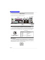
1
P4N Diamond
MS-7160 (v1.X) ATX Mainboard
G52-M7160X3
i
Manual Rev: 1.1
Release Date: Apr. 2005
FCC-B Radio Frequency Interference Statement
This equipment has been tested and found to comply with the limits for a class B
digital device, pursuant to part 15 of the FCC rules. These limits are designed to
provide reasonable protection against harmful interference when the equipment is
operated in a commercial environment. This equipment generates, uses and can
radiate radio frequency energy and, if not installed and used in accordance with the
instruction manual, may cause harmful interference to radio communications. Operation
of this equipment in a residential area is likely to cause harmful interference, in which
case the user will be required to correct the interference at his own expense.
Notice 1
The changes or modifications not expressly approved by the party responsible for
compliance could void the user’s authority to operate the equipment.
Notice 2
Shielded interface cables and A.C. power cord, if any, must be used in order to
comply with the emission limits.
VOIR LA NOTICE D’INSTALLATION AVANT DE RACCORDER AU RESEAU.
Micro-Star International
MS-7160
This device complies with Part 15 of the FCC Rules. Operation is subject to the
following two conditions:
(1) this device may not cause harmful interference, and
(2) this device must accept any interference received, including interference that
may cause undesired operation
ii
Copyright Notice
T he material in this document is the intellec tual property of M ICRO-STAR
INTERNATIONAL. W e take every care in the preparation of this document, but no
guarantee is given as to the correctness of its contents. Our products are under
continual improvement and we reserve the right to make changes without notice.
Trademarks
All trademarks are the properties of their respective owners.
AMD, Athlon™64 and Athlon™ FX are registered trademarks of AMD Corporation.
Intel® and Pentium® are registered trademarks of Intel Corporation.
PS/2 and OS ® /2 are registered trademarks of International Business Machines
Corporation.
Microsoft is a registered trademark of Microsoft Corporation. W indows ® 98/2000/NT/
XP are registered trademarks of Microsoft Corporation.
NVIDIA, the NVIDIA logo, DualNet, and nForce are registered trademarks or trademarks of NVIDIA Corporation in the United States and/or other countries.
Netware® is a registered trademark of Novell, Inc.
Award® is a registered trademark of Phoenix Technologies Ltd.
AMI® is a registered trademark of American Megatrends Inc.
Kensington and MicroSaver are registered trademarks of the Kensington Technology
Group.
PCMCIA and CardBus are registered trademarks of the Personal Computer Memory
Card International Association.
Revision History
Revision
V1.0
V1.1
Revision History
First release for PCB 1.X
with nForce4 SLI Intel Edition
Release for PCB 1.X
with nForce4 SLI Intel Edition (for EU)
iii
Date
Apr. 2005
Apr. 2005
Technical Support
If a problem arises with your system and no solution can be obtained from the user’s
manual, please contact your place of purchase or local distributor. Alternatively,
please try the following help resources for further guidance.
† Visit the MSI homepage & FAQ site for technical guide, BIOS updates, driver
updates, and other information: http://www.msi.com.tw & http://www.msi.
com.tw/program/service/faq/faq/esc_faq_list.php
† Contact our technical staff at: [email protected]
Safety Instructions
1.
2.
3.
4.
5.
Always read the safety instructions carefully.
Keep this User’s Manual for future reference.
Keep this equipment away from humidity.
Lay this equipment on a reliable flat surface before setting it up.
The openings on the enclosure are for air convection hence protects the equipment from overheating. Do not cover the openings.
6. Make sure the voltage of the power source and adjust properly 110/220V before connecting the equipment to the power inlet.
7. Place the power cord such a way that people can not step on it. Do not place
anything over the power cord.
8. Always Unplug the Power Cord before inserting any add-on card or module.
9. All cautions and warnings on the equipment should be noted.
10. Never pour any liquid into the opening that could damage or cause electrical
shock.
11. If any of the following situations arises, get the equipment checked by a service
personnel:
† The power cord or plug is damaged.
† Liquid has penetrated into the equipment.
† The equipment has been exposed to moisture.
† The equipment has not work well or you can not get it work according to
User’s Manual.
† The equipment has dropped and damaged.
† The equipment has obvious sign of breakage.
12. Do not leave this equipment in an environment unconditioned, storage
temperature above 60 0 C (140 0F), it may damage the equipment.
CAUT ION: Danger of explosion if battery is incorrec tly replac ed.
Replace only with the same or equivalent type recommended by the
manufacturer.
iv
CONTENTS
FCC-B Radio Frequency Interference Statement......................................................ii
Copyright Notice.......................................................................................................iii
Revision History.......................................................................................................iii
Technical Support....................................................................................................iv
Safety Instructions..................................................................................................iv
English..............................................................................................................E-1-1
1. Getting Started.........................................................................................E-1-3
2. Hardware Setup.......................................................................................E-2-1
3. BIOS Setup...............................................................................................E-3-1
Français...............................................................................................................F-1
Manuel d’utilisation..........................................................................................F-3
Deutsch...............................................................................................................G-1
Benutzerhandbuch.........................................................................................G-3
v
Getting Started
P4N Diamond
User’s Guide
English
E-1-1
M S-7160 ATX M ainboard
E-1-2
Getting Started
Chap t er 1 . Ge tting
Started
Getting Started
Thank you for choosing the P4N Diamond (MS-7160) v1.X
ATX mainboard. The P4N Diamond mainboard is based on nVIDIA®
nForce™4 SLI Intel Edition chipset for optimal system efficiency.
Designed to fit the advanced Intel® Pemtium 4 Extreme Edition,
Pentium 4, Pentium D, Pentium XE and Celeron D processors
in LGA775, the P4N Diamond mainboard delivers a high performance and professional desktop platform solution.
E-1-3
M S-7160 ATX M ainboard
Mainboard Specifications
CPU
† Supports Socket-775 for Intel® Pemtium 4 Extreme Edition, Pentium 4, Pentium D,
Pentium XE and Celeron D processors
† Supports Intel 05B and 05A processors
† Supports FSB 1066/ 800 MHz
† Supports Hyper-Threading (HT) Technology
(For the latest information about CPU, please visit http://www.msi.com.tw/program/
products/mainboard/mbd/pro_mbd_cpu_support.php)
Chipset
† nVIDIA nForce4 SLI Intel Edition North Bridge
- HyperTransport link to nVidia MCP04 south bridge
- Supports 2 PCI Express x 16 and 1 PCI Express x 1 interface
- Supports dual channel, DDR2 400/ 533/ 667
† nVIDIA nForce4 SLI Intel Edition MCP04 South Bridge
- Supports up at 4 GB/sec
- Integrate SATA-II controller, four drives
- Dual Fast-ATA 133 IDE controller, for four devices
- IEEE 802.3 nVIDIA MAC for 1000BASE-T
M ain M emory
† Supports dual channel, DDR2 400/ 533/ 667, using four 240-pin/ 1.8V DDR2
DIMMs
† Supports a maximum memory size up to 16GB
(For the updated supporting memory modules, please visit http://www.msi.com.tw/
program/products/mainboard/mbd/pro_mbd_trp_list.php.)
Slots
† Two PCI Express x16 slots by auto detect or software select normal or SLI mode
(supports PCI Express Bus specification v1.0a compliant)
SLI mode - Primary PCI _ E slot is compatible with PCI Express x 8
Secondary PCI_E slot is compatible with PCI Express x 8
non-SLI mode - Primary PCI_E slot is compatible with PCI Express x 16
Secondary PCI_E slot is compatible with PCI Express x 1
† One PCI Express x1 slot (supports PCI Express Bus specification v1.0a compliant)
† Two 32-bit Master PCI Bus slots, includes one orange slot which supports 2
master for MSI special PCI function card (ex. wireless LAN and bluetooth combo
card.).
† Support 3.3V/5V PCI bus Interface
On-Board IDE
† The IDE controller on the nVIDIA® nForce4 Intel Edition SLI MCP04 chip provides IDE
HDD/CD-ROM with PIO, Bus Master and Ultra DMA 66/100/133 operation modes.
† Can connect up to 4 IDE devices.
† Supports RAID 0/ 1/ 0+1/ RAID 5 or JBOD mode.
E-1-4
Getting Started
On-Board SATA
† MCP04 supports 4 SATA-II ports (SATA1-4). Transfer rate is up to 300 MB/s.
Supports RAID 0/ 1/ 0+1/ RAID 5 or JBOD mode.
† Silicon Image’s SATARAID supports another 2 SATA-II ports (SATA5/6).
Transfer rate is up to 300 MB/s. Supports RAID 0 & 1 mode. (optional)
USB Interface
† 10 USB ports
- Controlled by nForce4 SLI Intel Edition MCP04 chip
- 4 ports in the rear I/O, 6 ports via the external bracket
NV RAID
† Supports up to 4 SATA and 4 ATA133 Hard drives
- RAID 0, 1, 0+1, 5 or JBOD is supported
- RAID function available for ATA133/ SATA H/D or ATA133 + SATA H/D drives
- Supports up to 8 drives for RAID function.
Silicon Image’s SATARAID (Optional)
† RAID 0 or 1 and multiple RAID groups are supported
† Support up to 2 SATA devices
† Support External SATA devices by SATA Extend bracket
Dual Gigabit LAN
† Supports dual LAN jacks
- 1st LAN supports 10/100/1000 Fast Ethernet by nForce4 SLI Intel Edition
MCP04 south bridge
- 2nd PCI Express LAN supports 10/100/1000 Fast Ethernet by Marvell
88E8053 (optional)
IEEE 1394 (optional)
† Supports up to three 1394 ports (rear panel x 1, pinheader x 2). Transfer rate
is up to 400Mbps
Audio (either CA0106 or ALC850)
† Power by Creative Sound Bluster 24 bits H/W audio controller CA0106(optional)
- 24-bit / 96~192 KHz audio quality
- Up to 100 db SNR clarity
- 7.1 Channel output supported, Dolby Digital encoder
- Supports S/PDIF digital interface
- PCI 2.3 Specification compliant
† Chip integrated by Realtek ALC850 (7.1 ch S/W audio) (optional)
- Compliant with AC’97 2.3 Spec.
E-1-5
M S-7160 ATX M ainboard
On-Board Peripherals
† On-Board Peripherals include:
- 1 floppy port supports 1 FDD with 360K, 720K, 1.2M, 1.44M and 2.88Mbytes
- 1 serial port (COM1)
- 1 parallel port supporting SPP/EPP/ECP mode
- 1 Audio jack(5-in-1), coaxial/fiber SPDIF out
- 1 D-Bracket 2 pinheader
- 1 CD-In pinheader
- 3 IEEE 1394 (Rear * 1 / Front * 2)
- 10 USB1.1/2.0 ports (Rear * 4 / Front * 6)
- 1 IrDA pinheader
BIOS
† The mainboard BIOS provides “Plug & Play” BIOS which detects the peripheral
devices and expansion cards of the board automatically.
† The mainboard provides a Desktop Management Interface (DMI) function which
records your mainboard specifications.
† Supports boot from LAN, USB Device 1.1 & 2.0, and SATA HDD.
Dimension
† ATX Form Factor (30.5 cm X 24.4 cm)
M ounting
† 9 mounting holes
MSI Reminds You...
To create a bootable RAID volume for a Windows 2000 environment,
Microsoft’s Windows 2000 Service Pack 4 (SP4) is required. As the
end user cannot boot without SP4, a combination installation CD must
be created before attempting to install the operating system onto the
bootable RAID volume.
To create the combination installation CD, please refer to the following website:
http://www.microsoft.com/windows2000/downloads/servicepacks/
sp4/HFdeploy.htm
E-1-6
Getting Started
Mainboard Layout
PWRFAN1
CPUFAN1
Top : mouse
Bottom: keyboar d
PWR1
ATX1
FDD1
Top : Parallel Port
Bottom:
COM Port
1394 Port
SPDIF Out
Top: LAN Jack
Bottom: USB ports
Winbond
W82627THF
nvidia
Crush 19 SLI
DIMM2
JIR1 NBFAN1
T:RS-Out
M:CS-Out
B:SPDIFOut
88E-1111
IDE1
T:Line-In
M:Line-Out
B:Mic
IDE2
JCI1
Top: LAN Jack
Bottom: USB ports
DIMM4
DIMM3
JPWR1
JCD1
DIMM2
DIMM1
JDB1
PCI_E3
88E8053
PCI_E1
Primary (x16/ x8)
BATT
+
SATA2
SATA1
nvidia
MCP04
PCI E2
SATA3
Secondary (x1/ x8)
SW1
SATA4
SATA5
PCI1
SATA6
BIOS
VIA
VT6306
Creative
Sound
Bluster
Silicon
Image
SYSFAN1
PCI2
JUSB1
JAUD1
JUSB2
JUSB3
J1394_2
JFP2
JFP1
J1394_1
P4N Diamond (MS-7160 v1.X) ATX Mainboard
E-1-7
M S-7160 ATX M ainboard
Packing Contents
MSI motherboard
MSI Driver/Utility CD
SATA RAID Driver
Diskette/ Creative
Audio Driver
SATA Cable/
Power Cable (Optional)
External SATA 2 Cable
(Optional)
D-Bracket 2
Round Cable of
Floppy Disk
1394 Cable
(Optional)
Round Cable of
IDE Devices
SLI bridge
Back IO Shield
(Optional)
User’s Guide/ Quick
Guide/ Test Report
* The pictures are for reference only and may vary from the packing contents of
the product you purchased.
E-1-8
Getting Started
MSI Special Feature
Core CellTM Chip
By diagnosing the current system utilization, the CoreCell™
Chip automatically tunes your motherboard to the optimal state,
leading to less noise, longer duration, more power-saving and
higher performance.
Features of CoreCell™
Speedster
-- Advanced O.C. design.
-- Superior O.C. capability.
-- Greater O.C. method.
LifePro
-- Prolongs motherboard, CPU and fan life.
-- Maintains motherboard & CPU in constant temperature.
-- Prevents components from operating beyond specifications.
PowerPro
-- Saves up to 65% power.
-- Assures motherboard stability.
-- Empowers O.C capability.
BuzzFree
-- Diagnoses current system utilization & temperature.
-- Controls both CPU and NorthBridge fans.
-- Cuts up to 50% of system noise.
E-1-9
M S-7160 ATX M ainboard
D.O.T. Express(2nd generation of D.O.T.)
Dynamic Overclocking by REAL CPU Loading
† CoreCell chip detects CPU current as trigger point
† Fastest Response Time to report REAL CPU Loading:
- 1us response time, 5 times faster than competitor’s solution (by CPU VID,
5us response time.
- Slowest: Detect by Background Software
Dedicate power solution for DRAM and Chipset
† Steady Current Supply to ensure performance and stability
Real-Time Power Circuitry (PWM ) Protection
† Protect CPU when abnormal current occurred
† Response Time: 1us only - No competitor
E-1-10
Hardware Setup
Chapter 2. Hardware Setup
Hardware Setup
This chapter tells you how to install the CPU, memory modules,
and expansion cards, as well as how to setup the jumpers on the
mainboard. Also, it provides the instructions on connecting the peripheral devices, such as the mouse, keyboard, etc.
W hile doing the installation, be careful in holding the components and follow the installation procedures.
E-2-1
M S-7160 ATX M ainboard
Quick Components Guide
CPU, E-2-3
NBFAN1,
PWR1, E-2-16
E-2-10
CPUFAN1,
E-2-16
PWRFAN1, E-2-16
DDR DIMMs,
E-2-7
Back Panel
FDD1, E-2-16
I/O, E-2-12
ATX1, E-2-10
JCI1, E-2-17
JIR1, E-2-20
IDE1/2,E-2-17
JDB1, E-2-21
JCD1,E-2-20
JPWR1, E-2-10
SW1,
PCI_E3,
E-2-26
E-2-25
PCI_E1~E2,
E-2-26
SATA1~6,
E-2-18
PCI 1~2,
SYSFAN1, E-2-16
E-2-28
JFP2, E-2-19
JFP1, E-2-19
JAUD1, E-2-19
J1394_1~2,
E-2-21
E-2-2
JUSB1~3, E-2-20
Hardware Setup
Central Processing Unit: CPU
The mainboard supports Intel® Pentium 4 Prescott, Smithfield (DualCore)and
CederMill) processors. The mainboard uses a CPU socket called LGA775. W hen you
are installing the CPU, make sure to install the cooler to prevent overheating.
If you do not have the CPU cooler, contact your dealer to purchase and install them
before turning on the computer.
For the latest information about CPU, please visit http://www.msi.com.tw/
program/products/mainboard/mbd/pro_mbd_cpu_support.php.
MSI Reminds You...
Overheating
Overheating will seriously damage the CPU and system, always make
sure the cooling fan can work properly to protect the CPU from
overheating.
Replacing the CPU
While replacing the CPU, always turn off the ATX power supply or
unplug the power supply’s power cord from grounded outlet first to
ensure the safety of CPU.
Overclocking
This motherboard is designed to support overclocking. However, please
make sure your components are able to tolerate such abnormal setting,
while doing overclocking. Any attempt to operate beyond product specifications is not recommended. We do not guarantee the damages
or risks caused by inadequate operation or beyond product
specifications.
Introduction to LGA 775 CPU
The pin-pad side of LGA 775
CPU.
Alignment Key
Yellow triangle is the Pin 1 indicator
The surface of LGA 775 CPU.
Remember to apply some silicone heat transfer compound on
it for better heat dispersion.
Alignment Key
Yellow triangle is the Pin 1 indicator
E-2-3
M S-7160 ATX M ainboard
CPU & Cooler Installation
W hen you are installing the CPU, make sure the CPU has a cooler attached on the top to prevent overheating. If you do not have the cooler, contact
your dealer to purchase and install them before turning on the computer. Meanwhile,
do not forget to apply some silicon heat transfer compound on CPU before installing
the heat sink/cooler fan for better heat dispersion.
Follow the steps below to install the CPU & cooler correctly. W rong installation
will cause the damage of your CPU & mainboard.
1. The CPU has a land side cover on the
bottom to protect the CPU contact from
damage. Rotate it to make the pin 1
indicator (yellow triangle) in the leftbottom corner.
2. Take out the accompanying CPU Clip
and rotate it for the same direction
as the CPU (Pin 1 indicator is in the
left-bottom corner).
land side cover
3. Use 2 hands to remove the land side
cover (if any). Please note not to touch
the pins.
4. Align the two pin 1 indicators (the
triangles on the CPU & the CPU Clip),
and use the CPU Clip to clip the CPU
up, pressing the clips on both sides
to the center, as the arrows shown.
MSI Reminds You...
1. Confirm if your CPU cooler is firmly installed before turning on your
system.
2. Do not touch the CPU socket pins to avoid damaging.
3. The availability of the CPU land side cover depends on your CPU
packing.
E-2-4
Hardware Setup
5. The CPU socket has a plastic cap on
it to protect the contact from damage.
Before you have installed the CPU,
always cover it to protect the socket
pin.
6. Remove the cap from lever hinge side
(as the arrow shows). The pins of
socket reveal.
7. Lift the load lever up and open the
load plate.
8. Correctly align the triangle of CPU Clip
with the CPU chamfer, and the square
on the CPU Clip to the hook of the
socket.
9. Use your thumb and the middle fingers to push the clips to release the
CPU, then press down the CPU with
your index finger to allow the whole
module to be installed onto the CPU
socket.
10. The CPU is installed well on the CPU
socket.
E-2-5
M S-7160 ATX M ainboard
11. Visually inspect if the CPU is seated
well into the socket, then remove the
CPU Clip with 2 fingers. Then cover
the load plate back to the place.
12. Press down the load lever lightly
onto the load plate, and then secure
the lever with the hook under retention tab.
13. Align the holes on the mainboard with
the cooler. Push down the cooler until
its four c lips get wedged into the
holes of the mainboard.
14. Press the four hooks down to fasten
the cooler. Then rotate the locking
switch (refer to the correct direction
marked on it) to lock the hooks.
locking
switch
15. Turn over the mainboard to confirm
that th e c li p-en ds are c orrec tly
inserted.
Note: If you want to uninstall the CPU,
align the 4 points (see Setp 8 for
details) again and push the clip to
lift up the CPU.
MSI Reminds You...
1. Check the information in PC Health Status in BIOS (Chapter 3) for
the CPU temperature.
2. Whenever CPU is not installed, always protect your CPU socket pin
with the plastic cap covered (shown in step 5) to avoid damaging.
3. Please note that the mating/unmating durability of the CPU is 20 cycles.
Therefore we suggest you do not plug/unplug the CPU too often.
E-2-6
Hardware Setup
Memory
The mainboard provides 4 slots for 240-pin DDR2 DIMM, which supports the memory
size up to 16GB.
Since DDR2 modules are not interchangeable with DDR1 and the DDR2 standard is not backward compatible, you should always install DDR2 memory module in
the DDR2 slot (DIMM1~DIMM4). Otherwise, you are not able to boot up your system
and your mainboard might be damaged.
For the updated supporting memory modules, please visit http://www.msi.
com.tw/program/products/mainboard/mbd/pro_mbd_trp_list.php.
DIMM1~4
(from left (Green) to
right (Orange))
Channel A (DIMM1 & DIMM2): Green
Channel B (DIMM3 & DIMM4): Orange
Introduction to DDR2 SDRAM
DDR2 is a new technology of memory module, and its speed is the top limit of
current DDR1 technology. DDR2 uses a 1.8V supply for core and I/O voltage, compared to 2.5V for DDR1, and requires 28% less power than DDR1 chips. DDR2 truly
is the future of memory, but will require some changes as the technology is not
backwardly compatible and only motherboards specifically designed for DDR2 memory
will be able to support these chips.
DDR2 incorporates new features at the chip level that give it better signal
integrity, thereby enabling higher clock speeds.
DDR2 modules have 240 pins, versus 184 pins on a DDR1 module, and the
length of DDR2 module is 5.25”. DDR2 modules have smaller and tighter spaced pins.
The height of DDR2 modules varies, but they will typically be less than 1.3” in height.
E-2-7
M S-7160 ATX M ainboard
DIMM Module Combination
Install at least one DIMM module on the slots. Each DIMM slot supports up to a
maximum size of 4GB. Users can install either single- or double-sided modules to
meet their own needs. Please note that each DIM M can work respectively for
single-channel DDR2, but there are some rules while using dual-channel
DDR2 (Please refer to the suggested DDR population table below). Users may install
memory modules of different type and density on different-channel DDR DIMMs.
However, the same size, type and density memory modules are necessary
while using dual-channel DDR, or instability may happen. Please refer to the following
table for detailed dual-channel DDR. Other combination not listed below will function
as single-channel DDR.
GREEN
DIMM1 (Ch A)
GREEN
DIMM2 (Ch A)
256MB~4GB
ORANGE
ORANGE
DIMM3 (Ch B)
DIMM4 (Ch B)
256MB~4GB
256MB~4GB
512MB~8GB
256MB~4GB
256MB~4GB
256MB~4GB
512MB~8GB
256MB~4GB
256MB~4GB
256MB~4GB
256MB~4GB
System Density
512MB~8GB
256MB~4GB
512MB~8GB
256MB~4GB
1GB~16GB
MSI Reminds You...
- Please select the identical memory modules to install on the dual
channel, and DO NOT install three memory modules on three
DIMMs, or it may cause some failure.
- Always insert the memory modules into the GREEN slots first, and
it is strongly recommended not to insert the memory modules into
the ORANGE slots while the GREEN slots are left empty.
- This mainboard DO NOT support with-ECC DIMM.
- Enabling dual-channel simply means to make sure that to install 2 or
4 memory modules into different color DIMM sockets.
E-2-8
Hardware Setup
Installing DDR2 Modules
1. The DDR2 DIMM has only one notch on the center of module. The module will only
fit in the right orientation.
2. Insert the DIMM memory module vertically into the DIMM slot. Then push it in until
the golden finger on the memory module is deeply inserted in the socket.
3. The plastic clip at each side of the DIMM slot will automatically close.
Volt
Notch
MSI Reminds You...
You can barely see the golden finger if the module is properly inserted in the socket.
E-2-9
M S-7160 ATX M ainboard
Power Supply
The mainboard supports ATX power supply for the power system. Before
inserting the power supply connector, always make sure that all components are
installed properly to ensure that no damage will be caused.
ATX 24-Pin Power Connector: ATX1
This connector allows you to connect an SSI power supply. To connect the
SSI power supply, make sure the plug of the power supply is inserted in the proper
orientation and the pins are aligned. Then push down the power supply firmly into
the connector.
Pin Definition
13
1
ATX1
24
12
PIN
SIGNAL
PIN
SIGNAL
1
2
+3.3V
+3.3V
13
14
+3.3V
-12V
3
4
GND
+5V
15
16
GND
PS-ON#
5
6
GND
+5V
17
18
GND
GND
7
8
GND
PWR OK
19
20
GND
-5V (optional)
9
10
5VSB
+12V
21
22
+5V
+5V
11
+12V
12
+3.3V
23
24
+5V
GND
ATX 12V Power Connector: PWR1 & JPWR1
3
1
PWR1 Pin Definition
4
2
PWR1
PIN
SIGNAL
1
2
GND
GND
3
4
12V
12V
JPWR1 Pin Definition
1
2
3
JPWR1
4
PIN
SIGNAL
1
5V
2
3
GND
GND
4
+12V
MSI Reminds You...
1. These two connectors connect to the ATX power supply and have to
work together to ensure stable operation of the mainboard.
2. Power supply of 450 watts (and above) is highly recommended for
system stability.
3. For ATX 12V power connection, it should be greater than 20A.
E-2-10
Hardware Setup
Important Notification about Power Issue
NForce chipset is very sensitive to ESD (Electrostatic Discharge), therefore
this issue mostly happens while the users intensively swap memory modules under
S5 (power-off) states, and the power code is plugged while installing modules. Due
to several pins are very sensitive to ESD, so this kind of memory-replacement actions
might cause system chipset unable to boot. Please follow the following solution to
avoid this situation.
Unplug the AC power cable (shown in figure 1) or unplug the ATX1, PW R1 and
JPW R1 power connectors (the figure 2 & 3 are for referance only) before the 1st
installation or during system upgrade procedure.
Figure 1:
Unplug the AC power cable
Figure 2:
Unplug the ATX1 power conn.
Figure 3:
Unplug the PWR1 & JPWR1 power
connectors
E-2-11
M S-7160 ATX M ainboard
Back Panel
The back panel provides the following connectors:
L-In
Parallel
LAN
M ou se
Keyboard
COM Port
1394 Port
SPDIF
Out
(Coaxial)
RS-Out
LAN
USB Ports
L-Out CS-Out
Mic SPDIF Out
(Optical)
Mouse Connector (Green) / Keyboard Connector (Purple)
The mainboard provides a standard PS/2® mouse/keyboard mini DIN connector
for attaching a PS/2® mouse/keyboard. You can plug a PS/2® mouse/keyboard directly
into this connector. The connector location and pin assignments are as follows:
Pin Definition
6
5
3
4
2
1
PS/2 Mouse / Keyboard
(6-pin Female)
PIN
SIGNAL
DESCRIPTION
1
2
Mouse/Keyboard Data
NC
Mouse/Keyboard data
No connection
3
4
GND
VCC
Ground
+5V
5
6
Mouse/KeyboardClock
NC
Mouse/Keyboard clock
No connection
IEEE1394 Port
The back panel provides one standard IEEE 1394 port. The IEEE1394 highspeed serial bus complements USB by providing enhanced PC connectivity for a
wide range of devices, including consumer electronics audio/video (A/V) appliances,
storage peripherals, other PCs, and portable devices.
IEEE1394 Port
E-2-12
Hardware Setup
Serial Port Connector
The mainboard offers one 9-pin male DIN connector as the serial port. The port
is a 16550A high speed communication port that sends/receives 16 bytes FIFOs. You
can attach a serial mouse or other serial devices directly to the connector.
Pin Definition
1 2
6
3
7
4
8
5
9
9-Pin Male DIN Connector
PIN
SIGNAL
DESCRIPTION
1
DCD
Data Carry Detect
2
3
SIN
SOUT
Serial In or Receive Data
Serial Out or Transmit Data
4
5
DTR
GND
Data Terminal Ready)
Ground
6
7
DSR
RTS
Data Set Ready
Request To Send
8
9
CTS
RI
Clear To Send
Ring Indicate
USB Connectors
The mainboard provides two OHCI (Open Host Controller Interface) Universal
Serial Bus roots for attaching USB devices such as keyboard, mouse or other USBcompatible devices. You can plug the USB device directly into the connector.
USB Port Description
1
2
3
4
5
6
7
8
USB Ports
PIN
SIGNAL
DESCRIPTION
1
2
VCC
-Data 0
+5V
Negative Data Channel 0
3
4
+Data0
GND
Positive Data Channel 0
Ground
5
6
VCC
-Data 1
+5V
Negative Data Channel 1
7
8
+Data 1
GND
Positive Data Channel 1
Ground
E-2-13
M S-7160 ATX M ainboard
LAN (RJ-45) Jack
The mainboard provides 2 standard RJ-45 jacks for connection to single Local
Area Network (LAN). This Giga-bit LAN enables data to be transferred at 1000, 100
or 10Mbps. You can connect a network cable to either LAN jack.
Giga-bit LAN Pin Definition
RJ-45 LAN Jack
PIN
SIGNAL
DESCRIPTION
1
D0P
Differential Pair 0+
2
D0N
Differential Pair 0-
3
D1P
Differential Pair 1+
4
D2P
Differential Pair 2+
5
D2N
Differential Pair 2-
6
D1N
Differential Pair 1-
7
D3P
Differential Pair 3+
8
D3N
Differential Pair 3-
Audio Port Connectors
The left 3 audio jacks are for 2-channel mode for stereo speaker output: Line
Out is a connector for Speakers or Headphones. Line In is used for external CD
player, Tape player, or other audio devices. Mic is a connector for microphones.
However, there is an advanced audio application provided by Creative CA0106 or
Realtek ALC850 to offer support for 7.1-channel audio operation and can turn
rear audio connectors from 2-channel to 4-/5.1-/7.1 channel audio.
S/PDIF Out-Coaxial
Line In/
Side Surround Out
Line Out
M IC
E-2-14
Rear Speaker Out
Center/Subwoofer
Speaker Out
S/PDIF Out-Optical
Hardware Setup
Parallel Port Connector: LPT1
The mainboard provides a 25-pin female centronic connector as LPT. A parallel
port is a standard printer port that supports Enhanced Parallel Port (EPP) and Extended Capabilities Parallel Port (ECP) mode.
13
1
14
25
Pin Definition
PIN
SIGNAL
DESCRIPTION
1
2
STROBE
DATA0
Strobe
Data0
3
4
DATA1
DATA2
Data1
Data2
5
6
DATA3
DATA4
Data3
Data4
7
8
DATA5
DATA6
Data5
Data6
9
10
DATA7
ACK#
Data7
Acknowledge
11
12
BUSY
PE
Busy
PaperEnd
13
14
SELECT
AUTO FEED#
Select
AutomaticFeed
15
16
ERR#
INIT#
Error
Initialize Printer
17
18
SLIN#
GND
Select In
Ground
19
20
GND
GND
Ground
Ground
21
22
GND
GND
Ground
Ground
23
24
GND
GND
Ground
Ground
25
GND
Ground
E-2-15
M S-7160 ATX M ainboard
Connectors
The mainboard provides connectors to connect to FDD, IDE HDD, case, LAN,
USB Ports, IR module and CPU/System FAN.
Floppy Disk Drive Connector: FDD1
The mainboard provides a standard floppy disk drive connector that supports
360K, 720K, 1.2M, 1.44M and 2.88M floppy disk types.
FDD1
Fan Power Connectors: CPUFAN1/ PWRFAN1/ SYSFAN1/ NBFAN1
The CPUFAN1 (processor fan), SYSFAN1 (system fan 1), PW RFAN1(power
fan) and NBFAN1 (NorthBridge Chipset fan) support system cooling fan with +12V.
The CPUFAN1 supports Smart FAN function. W hen connecting the wire to the
connectors, always take note that the red wire is the positive and should be connected to the +12V, the black wire is Ground and should be connected to GND. If the
mainboard has a System Hardware Monitor chipset on-board, you must use a specially designed fan with speed sensor to take advantage of the CPU fan control.
GND
+12V
Sensor
Control
CPUFAN1
NC +12V GND
PW RFAN1
GND
+12V
NC
Sensor
SYSFAN1
+12V
GND
NBF AN1
MSI Reminds You...
1. Always consult the vendors for proper CPU cooling fan.
2. CPUFAN1 supports fan control. You can install Core Center utility that will automatically control the CPU fan speed according to
the actual CPU temperature.
3. Fan/heatsink with 3 or 4 pins are both available for CPUFAN1.
Please note that only install 4 pins FAN/heatsing support Smart
FAN.
4. Please refer to the recommended CPU fans at Intel® official website.
E-2-16
Hardware Setup
Hard Disk Connectors: IDE1 / IDE2
The mainboard has a 32-bit Enhanced PCI IDE and Ultra DMA 33/66/100/133
controller that provides PIO mode 0~4, Bus Master, and Ultra DMA 33/66/100/133
function. You can connect up to four IDE drives such as Hard Drive, CD-ROM, or
other devices.
IDE2 IDE1
IDE1 (Primary IDE Connector)
The first hard drive should always be connected to IDE1. IDE1 can connect a
Master and a Slave drive. You must configure second hard drive to Slave mode by
setting the jumper accordingly.
IDE2 (Secondary IDE Connector)
IDE2 can also connect a Master and a Slave drive.
MSI Reminds You...
If you install two hard disks on cable, you must configure the second
drive to Slave mode by setting its jumper. Refer to the hard disk
documentation supplied by hard disk vendors for jumper setting
instructions.
Chassis Intrusion Switch Connector: JCI1
This connector is connected to a 2-pin chassis switch. If the
chassis is opened, the switch will be short. The system will record
this status and show a warning message on the screen. To clear
the warning, you must enter the BIOS utility and clear the record.
CINTRU
GND
1
2
JCI1
E-2-17
M S-7160 ATX M ainboard
Serial ATA Connectors: SATA1 ~ 4 & SATA5 ~ 6
The single chip of this mainboard is nForce4 SLI Intel Edition MCP04 chipset
which supports f our serial ATA connec tors SATA1~SATA4. Silicon Image’s
SATARAID of this mainboard supports another two serial ATA connectors SATA5/
SATA6.
SATA1~SATA6 are high-speed Serial ATA interface ports. Each supports serial
ATA data rates of 300MB/s. Both connectors are fully compliant with Serial ATA 2.0
specifications. Each Serial ATA connector can connect to 1 hard disk device. Please
refer to the nVidia RAID Introduction & Silicon Image RAID Introduction for detail
software installation procedure.
SATA2
1
Pin Definition
7
SATA1
SATA3
1
PIN
SIGNAL
PIN
SIGNAL
1
GND
2
TXP
3
5
TXN
RXN
4
6
GND
RXP
7
GND
7
Take out the dust cover
SATA4
Serial ATA cable
SATA5
(optional)
1
and connect to the hard
disk devices.
7
SATA6
Connect to serial ATA ports
Connect to SATA5 & SATA6)
(the SATA connectors in BLUE color)
Extend SATA2 Bracket for
Silicon Image SATAII only
(Optional)
You have to connect the SATA device
which has own independent power supply.
MSI Reminds You...
Please do not fold the serial ATA cable in a 90-degree angle, which will
cause the loss of data during the transmission.
E-2-18
Hardware Setup
Front Panel Connectors: JFP1 / JFP2
The mainboard provides two front panel connectors for electrical connection
to the front panel switches and LEDs. JFP1 is compliant with Intel® Front Panel I/O
Connectivity Design Guide.
JFP1 Pin Definition
Power Power
LED Switch
JFP1
10
9
2
1
HDD Reset
LED Switch
PIN
SIGNAL
DESCRIPTION
1
HD_LED_P
Hard disk LED pull-up
2
3
FP PWR/SLP
HD_LED_N
MSG LED pull-up
Hard disk active LED
4
5
FP PWR/SLP
RST_SW_N
MSG LED pull-up
Reset Switch low reference pull-down to GND
6
7
PWR_SW_P
RST_SW_P
Power Switch high reference pull-up
Reset Switch high reference pull-up
8
9
PWR_SW_N
RSVD_DNU
Power Switch low reference pull-down to GND
Reserved. Do not use.
JFP2 Pin Definition
Speaker
JFP2
2
1
8
7
Power
LED
PIN
SIGNAL
PIN
SIGNAL
1
GND
2
SPK-
3
5
SLED
PLED
4
6
BUZ+
BUZ-
7
NC
8
SPK+
Front Panel Audio Connector: JAUD1
The AUD1 front panel audio connector allows you to connect to the front panel
audio and is compliant with Intel® Front Panel I/O Connectivity Design Guide.
Pin Definition
JAUD1
2
1
10
9
PIN
SIGNAL
DESCRIPTION
1
AUD_MIC
Front panel microphone input signal
2
3
AUD_GND
AUD_MIC_BIAS
Ground used by analog audio circuits
Microphone power
4
5
AUD_VCC
AUD_FPOUT_R
Filtered +5V used by analog audio circuits
Right channel audio signal to front panel
6
7
AUD_RET_R
HP_ON
Right channel audio signal return from front panel
Reserved for future use to control headphone amplifier
8
9
KEY
AUD_FPOUT_L
No pin
Left channel audio signal to front panel
10
AUD_RET_L
Left channel audio signal return from front panel
MSI Reminds You...
If you don’t want to connect to the front audio header,
pins 5 & 6, 9 & 10 have to be jumpered in order to have
signal output directed to the rear audio ports. Otherwise,
the Line-Out connector on the back panel will not
function.
6
10
5
9
E-2-19
M S-7160 ATX M ainboard
Front USB Connectors: JUSB1 / JUSB2 / JUSB3
The mainboard provides three standard USB 2.0 pin headers JUSB1 & JUSB2
& JUSB3. USB 2.0 technology increases data transfer rate up to a maximum throughput
of 480Mbps, which is 40 times faster than USB 1.1, and is ideal for connecting highspeed USB interface peripherals such as USB HDD, digital cameras, MP3 players,
printers, modems and the like.
JUSB1 & JUSB2 & JUSB3 Pin Definition
2
1
10
9
JUSB1, JUSB2, JUSB3
(USB 2.0)
PIN
SIGNAL
PIN
SIGNAL
1
VCC
2
VCC
3
USB0-
4
USB1-
5
USB0+
6
USB1+
7
GND
8
GND
9
Key (no pin)
10
USBOC
Connected to JUSB1, JUSB2, or JUSB3
(the USB pinheader in YELLOW color)
USB 2.0 Bracket
(Optional)
MSI Reminds You...
Note that the pins of VCC and GND must be connected correctly, or
itmay cause some damage.
IrDA Infrared Module Header: JIR1
The connector allows you to connect to IrDA Infrared module. You must configure the setting through the BIOS setup to use the IR function. JIR1 is compliant with
Intel® Front Panel I/O Connectivity Design Guide.
Pin Definition
6
5
2
1
JIR1
Pin
Signal
Pin
Signal
1
3
NC
VCC5
2
4
NC
GND
5
IRTX
6
IRRX
CD-In Connector: JCD1
The connector is for CD-ROM audio connector.
E-2-20
JCD1
R
GND
GND
L
Hardware Setup
IEEE 1394 Connectors: J1394_1 / J1394_2
The mainboard provides two 1394 pin headers that allow you to connect IEEE
1394 ports via an external IEEE1394 bracket.
Pin Definition
1
2
9
10
J1394_1/ J1394_2
PIN
SIGNAL
PIN
SIGNAL
1
TPA+
2
TPA-
3
Ground
4
Ground
5
TPB+
6
TPB-
7
Cable power
8
Cable power
9
Key (no pin)
10
Ground
IEEE1394 Bracket
(Optional)
Foolproof Design
(the 1394 pinheader in GREEN color)
D-Bracket™ 2 Connector: JDB1
The mainboard comes with a JDB1 connector for you to connect to D-Bracket™
2. D-Bracket™ 2 is a USB Bracket that supports both USB1.1 & 2.0 spec. It integrates
four LEDs and allows users to identify system problem through 16 various combinations of LED signals.
Pin Definition
Pin
1
2
9
10
JDB1
Signal
1
2
DBG1 (high for green color)
DBR1 (high for red color)
3
4
DBG2 (high for green color)
DBR2 (high for red color)
5
6
DBG3 (high for green color)
DBR3 (high for red color)
7
8
DBG4 (high for green color)
DBR4 (high for red color)
9
10
Key
NC
E-2-21
M S-7160 ATX M ainboard
D-Bracket™ 2
Connected to JDB1
(Optional)
Connected to JUSB1, JUSB2 or JUSB3
(the USB pinheader in YELLOW color)
LEDs
D-Bracket™ 2 is an external USB bracket integrating four Diagnostic LEDs,
which use graphic signal display to help users understand their system. The LEDs
provide up to 16 combinations of signals to debug the system. The 4 LEDs can debug
all problems that fail the system, such as VGA, RAM or other failures. This special
feature is very useful for the overclocking users. These users can use the feature to
detect if there are any problems or failures.
D-Bracket™ 2 supports both USB 1.1 & 2.0 specification.
1
3
D-Bracket™ 2
Red
2
4
G reen
D-Bracket™ 2
1
2
3
4
Description
System Power ON
The D-LED will hang here if the processor is damaged or
not installed properly.
Early Chipset Initialization
Memory Detection Test
Testing onboard memory size. The D-LED will hang if the
memory module is damaged or not installed properly.
E-2-22
Hardware Setup
Decompressing BIOS image to RAM for fast booting.
Initializing Keyboard Controller.
Testing VGA BIOS
This will start writing VGA sign-on message to the screen.
Processor Initialization
This will show information regarding the processor (like
brand name, system bus, etc...)
Testing RTC (Real Time Clock)
Initializing Video Interface
This will start detecting CPU clock, checking type of video
onboard. Then, detect and initialize the video adapter.
BIOS Sign On
This will start showing information about logo, processor brand name, etc...
Testing Base and Extended Memory
Testing base memory from 240K to 640K and extended
memory above 1MB using various patterns.
Assign Resources to all ISA.
Initializing Hard Drive Controller
This will initialize IDE drive and controller.
E-2-23
M S-7160 ATX M ainboard
D-Bracket™ 2
Description
Initializing Floppy Drive Controller
This will initialize Floppy Drive and controller.
Boot Attempt
This will set low stack and boot via INT 19h.
Operating System Booting
E-2-24
Hardware Setup
Button
The motherboard provides the following jumpers for you to set the computer’s
function. This section will explain how to change your motherboard’s function through
the use of button.
Clear CMOS Button: SW1
There is a CMOS RAM on board that has a power supply from external battery
to keep the system configuration data. W ith the CMOS RAM, the system can automatically boot OS every time it is turned on. If you want to clear the system configuration,
use the SW 1 (Clear CMOS Button) to clear data. Press the button in the middle of the
connector top side to clear the data.
SW1
E-2-25
M S-7160 ATX M ainboard
Slots
The mainboard provides one PCI Express x 1 slot, two PCI Express x16 slots
and two 32-bit PCI bus slots.
PCI Express Slots: PCI_E1 (Primary)/ PCI _E2 (Secondary)/ PCI_E3
The PCI Express slots, as a high-bandwidth, low pin count, serial, interconnect technology, support Intel highest performance desktop platforms utilizing the
Intel Pentium 4 processor with HT Technology with these platform benefits. You can
insert the expansion cards to meet your needs. W hen adding or removing expansion
cards, make sure that you unplug the power supply first.
PCI Express architecture provides a high performance I/O infrastructure for
Desktop Platforms with transfer rates starting at 2.5 Giga transfers per second over
a PCI Express x1 lane for Gigabit Ethernet, TV Tuners, 1394 controllers, and general
purpose I/O. Also, desktop platforms with PCI Express Architecture will be designed
to deliver highest performance in video, graphics, multimedia and other sophisticated
applications. Moreover, PCI Express architecture provides a high performance graphics
(PDF, 166Kb) infrastructure for Desktop Platforms doubling the capability of existing
AGP8x designs with transfer rates of 4.0 GB/s over a PCI Express x16 lane for
graphics controllers, while PCI Express x1 supports transfer rate of 250 MB/s.
You can insert expansion card to meet your needs. W hen adding or removing
expansion cards, make sure that you unplug the power supply first.
PCI Express x16 slot
( PC I_ E1 ( Pr im ar y ) /
PCI_E2 (Secondary))
PCI Express x1 slot
(PCI_E3)
NV SLI (Scalable Link Interface) Multi-GPU Technology
NVIDIA SLI (Scalable Link Interface) technology allows two GPUs to run in
tandem within a system to achieve up to twice the performance of a single graphics
card. To utilize this technology, the two GPU cards must be connected by an SLI
bridge card. The mainboard can auto detect the SLI mode by software, therefore
you don’t have to configure the SLI mode onboard by yourself. (See “SLI Mode
Select” of Cell Menu section in BIOS for more details.) Following the process below
to complete SLI mode:
1. Installing two SLI-ready graphics cards in both PCIE x 16 slots, a bridge PCB
is used to connect the atop golden fingers of the both cards (fig.1). Please note that
you only need to connect a monitor to the Primary PCI Express card; although you
have installed two graphics cards, only the video outputs on the first card will work.
E-2-26
Hardware Setup
SLI bridge
Fig.1
MSI Reminds You...
1. Mainboard photos shown in this section are for demonstration only.
The appearance of your mainboard may vary depending on the model
you purchase.
2. If you intend to install only ONE graphics card, make sure that your
graphics card is Installed on the PCI_E1 (Primary) slot.
3. If you intend to install TWO SLI-ready graphics cards, make sure that
these two graphics cards are of the same brand and specifications.
4. Only Windows XP OS supports the SLI function.
2. After the hardware installation is completed, restart the system and install
the NV SLI driver/utility to graphics cards. A configuration panel will be provided for
Multi-GPU control. Check the Enable multi-GPU box to enable the SLI function for
the onboard graphics cards (concerning the details of multi-GPU settings, please
refer to your graphics card manual) .
Check the box.
E-2-27
M S-7160 ATX M ainboard
3. Restart your system and a pop-up will show in the system tray confirming
that M ulti-GPU has been enabled.
MSI Reminds You...
If you want to remove one graphics and change the status from SLI
mode to normal, make sure that you have to unclick the "MultiGPU"
before removing the graphics card and change back to normal mode.
PCI (Peripheral Component Interconnect) Slots: PCI1/ PCI2
The PCI slots allow you to insert the expansion cards to meet your needs.
W hen adding or removing expansion cards, make sure that you unplug the power
supply first. Meanwhile, read the documentation for the expansion card to make any
necessary hardware or software settings for the expansion card, such as jumpers,
switches or BIOS configuration.
The orange PCI slot (PCI2) also works as a communcation slot, which allows
you to insert the communcation card.
PCI Slots
PCI Interrupt Request Routing
The IRQ, acronym of interrupt request line and pronounced I-R-Q, are hardware lines over which devices can send interrupt signals to the microprocessor. The
PCI IRQ pins are typically connected to the PCI bus INT X# ~ INT Z# pins as follows:
E-2-28
Order 1
Order 2
Order 3
Order 4
PCI Slot 1
INT Y#
INT Z#
INT W#
INT X#
PCI Slot 2
INT Z#
INT W#
INT X#
INT Y#
BIOS Setup
Chapter 3. BIOS Setup
BIOS Setup
This chapter provides information on the BIOS Setup program and
allows you to configure the system for optimum use.
You may need to run the Setup program when:
² An error message appears on the screen during the system booting up, and requests you to run SETUP.
² You want to change the default settings for customized
features.
MSI Reminds You...
1. The items under each BIOS category described in this chapter are
under c ontinuous update for better s y s tem performanc e.
Therefore, the description may be slightly different from the latest
BIOS and should be held for reference only.
2. While booting up, the BIOS version is shown in the 1st line appearing after the memory counting. It is usually in the format:
example: A7160NMS V1.0 032405
where:
1st digit refers to BIOS maker as A=AMI(R); W=AWARD(R)
2nd - 5th digit refers to the model number.
6th digit refers to the customer, MS=all standard customers.
V1.0 refers to the BIOS version.
032405 refers to the date this BIOS is released.
E-3-1
M S-7160 ATX M ainboard
Entering Setup
Power on the computer and the system will start POST (Power On Self Test) process.
W hen the message below appears on the screen, press <DEL> key to enter Setup.
DEL: Setup Menu
TAB: Logo
F11: Boot Menu
If the message disappears before you respond and you still wish to enter Setup,
restart the system by turning it OFF and On or pressing the RESET button. You may
also restart the system by simultaneously pressing <Ctrl>, <Alt>, and <Delete> keys.
Selecting the First Boot Device
You are allowed to select the 1st boot device without entering the BIOS setup utility
by pressing <F11>. W hen the same message as listed above appears on the screen,
press <F11> to trigger the boot menu.
The POST messages might pass by too quickly for you to respond in time. If so,
restart the system and press <F11> after around 2 or 3 seconds to activate the boot
menu similar to the following.
Select First Boot Device
Floppy
: 1st Floppy
IDE-0
: IBM-DTLA-307038
CDROM
: ATAPI CD-ROM DRIVE 40X M
[Up/Dn] Select
[RETURN] Boot
[ESC] cancel
The boot menu will list all the bootable devices. Select the one you want to boot from
by using arrow keys and then pressing <Enter>. The system will boot from the
selected device. The selection will not make changes to the settings in the BIOS setup
utility, so next time when you power on the system, it will still use the original first
boot device to boot up.
E-3-2
BIOS Setup
Control Keys
<↑>
Move to the previous item
<↓>
Move to the next item
<←>
Move to the item in the left hand
<→>
Move to the item in the right hand
<Enter>
Select the item
<Esc>
Jumps to the Exit menu or returns to the main menu from a
submenu
<+>
Increase the numeric value or make changes
<->
Decrease the numeric value or make changes
<F6>
Load Optimized Defaults
<F7>
Load Fail-Safe Defaults
<F10>
Save all the CMOS changes and exit
Getting Help
After entering the Setup utility, the first screen you see is the Main Menu.
Main Menu
The main menu displays the setup categories the BIOS supplies. You can use the
arrow keys to select the item. The on-line description for the selected setup category
is displayed at the bottom of the screen.
Default Settings
The preset Optimal Defaults of the BIOS setup program provide optimal performance
settings for all devices and the system.
MSI Reminds You...
The items under each BIOS category described in this chapter are
under continuous update for better system performance. Therefore, the
description may be slightly different from the latest BIOS and should be
held for reference only.
E-3-3
M S-7160 ATX M ainboard
The Main Menu
Once you enter AMIBIOS CMOS SETUP UTILITY, the Main Menu will appear on the
screen. Use arrow keys to move among the items and press <Enter> to enter the
sub-menu.
Cell M enu
Use this menu to specify your settings for CPU/AGP frequency/voltage control and
overclocking.
Standard CMOS Features
Use this menu for basic system configurations, such as time, date etc.
Advanced BIOS Features
Use this menu to setup the items of AWARD ® special enhanced features.
Advanced Chipset Features
Use this menu to change the values in the chipset registers and optimize your system’s performance.
Integrated Peripherals
Use this menu to specify your settings for integrated peripherals.
Power M anagement Setup
Use this menu to specify your settings for power management.
PNP/PCI Configurations
This entry appears if your system supports PnP/PCI.
PC Health Status
This entry shows your PC health status.
E-3-4
BIOS Setup
Load Fail-Safe Defaults
Use this menu to load the default values set by the BIOS vendor for stable system
performance.
Load Optimized Defaults
Use this menu to load the default values set by the mainboard manufacturer specifically for optimal performance of the mainboard.
BIOS Setting Password
Use this menu to set the password for BIOS.
Save & Exit Setup
Save changes to CMOS and exit setup.
Exit Without Saving
Abandon all changes and exit setup.
E-3-5
M S-7160 ATX M ainboard
nVidia RAID Setup
nVidia RAID Setup
Press <Enter> to enter the sub-menu and the following screen appears:
nVidia RAID Function
This field is used to enable/disable the nVidia RAID function. W hen you set to
enable and the following fileds will appear and can be selectabled.
Setting options:
[Disabled]
Disable the nVidia RAID function
[Enabled]
W hen you set to “enabled” the following items will appear as
shown below. Allows you to enable the RAID function for
the hard drives which controlled by nVidia chipset.
PATA Primary/Secondary M aster/Slave
SATA1/2 Primary/Secondary channel
After the “nVidia RAID Function” is enabled, these fields will appear. These
fields are used to enable/disable the RAID function for the hard drives controlled
by nVidia chipset. Setting options:
[Disabled]
Disable the nVidia RAID function
[Enabled]
Enable the RAID function for the hard drive.
E-3-6
BIOS Setup
Onboard Device Configuration
Onboard Devices Configuration
Press <Enter> to enter the sub-menu and the following screen appears:
Onboard LAN Controller (for Marvell 88E8053 LAN)
The field enables or disables the onboard LAN controller. Setting options:
[Enabled], [Disabled].
Onboard IEEE1394 Controller
The field enables or disables the onboard IEEE1394 controller. Setting options:
[Enabled], [Disabled].
Onboard Silicon RAID Controller
The field enables or disables the onboard Silicon RAID controller. Before you
want to use silicon RAID for hard drives, you have to set this field to “RAID” first.
Setting options:
[Disabled]
Disables Onboard Silicon RAID controller
[RAID]
Enables Onboard Silicon RAID controller into RAID mode
[Non-Raid]
Enables Onboard Silicon RAID controller into non-RAID mode
Onboard Audio Controller
The field enables or disables the onboard Audio controller. Setting options:
[Enabled], [Disabled].
Onboard M AC LAN Controller (for nVidia chipsets)
The field enables or disables the onboard MAC LAN controller. Setting options:
[Enabled] and [Disabled].
E-3-7
M S-7160 ATX M ainboard
PC Health Status
This section shows the status of your CPU, fan, overall system status, etc.
Monitor function is available only if there is hardware monitoring mechanism onboard.
Chassis Intrusion
The field enables or disables the feature of recording the chassis intrusion status
and issuing a warning message if the chassis is once opened. This item is available
only when your mainboard has JCI1 jumper. To clear the warning message, set the
field to [Reset]. The setting of the field will automatically return to [Enabled] later.
Settings: [Enabled], [Reset], [Disabled].
CPU Smart Fan Target Temp Select
W hen the current temperature of the CPU fan reaches the value you specify here,
the CPU fan will speed up for cooling down to avoid the CPU damage; on the contrary,
if the CPU fan current temperature is lower than the specified value, the CPU fan will
slow down its speed to keep the temperature stable.
Smart CPU Fan Tolerance
You can select a fan tolerance value here for the specific range for the Smart CPU
Fan Target Temp Select items. If the current temperatures of CPU fan reach to the
maximum threshold (the temperatures set in the Smart CPU Fan Target Temp
Select plus the tolerance values you set here), the fans will speed up for cooling
down. On the contrary if the current temperatures reach to the minimum threshold
(the set temperatures minus the tolerance values), the fans will slow down to keep
the temperatures stable.
CPU/System Temperature, CPU/NB FAN Speed, CPU Vcore, +3.3 V, +5.0 V,
+12.0V, +5VSB
These items display the current status of all of the monitored hardware devices/
components such as CPU voltages, temperatures and all fans’ speeds.
E-3-8
BIOS Setup
Cell Menu
The items in Cell Menu includes some important settings of CPU, PCIE, DRAM
and overclocking functions.
MSI Reminds You...
Change these settings only if you are familiar with the chipset.
Current CPU Clock
This field shows the current clocks of CPU. Read-only.
Current FSB/ M emory Speed
These fields show the current FSB/ Memory Speed. Read-only.
System Clock M ode
This field allow you to set the System clock mode or overclock for CPU and memory.
Setting options:
[Auto]
Set FSB & Memory clock automatically.
[Linked]
Allows Memory and FSB to overclock proportionally.
[Manual]
Enter FSB and Memory clock manually.
MSI Reminds You...
We suggest user to make sure that your CPU and memory can afford to
overclocking regularly first. If you find the PC appears to be Unstable
or reboot incidentally, it’s better to disable the Overclocking or to
lower the level of overclocking options.
E-3-9
M S-7160 ATX M ainboard
CPU Ratio CMOS Setting
This field shows the CPU Ratio which detected by CMOS. Read-only
PCIE Frequency
This field allows you to select the PCIE frequency (in MHz). Select the number between [100]~[145] for needeed frequency.
SLI M ode Select
This fiels allows you to enable or disable the SLI mode. W hen you install a pair of
identical SLI-readygraphics cards of the GeForce family into the system and enable
the SLI mode, both PCI Express x16 slots transform into PCI Express x8 ones.
Setting options:
[Auto]
System auto detect and enable the SLI mode. If the system detects
SLI mode, the both PCI Express x16 slots transform into PCI
Express x8 mode.
[x16, x1]
Disable the SLI mode. Primary PCIEx16 slot will transform into x16
mode, and Secondary PCIEx16 slot will transform into x1 mode.
Voltage Control Function
Press <Enter> to enter the sub-menu and the following screen appears:
Adjust CPU Voltage (V)
This feature allows you to trim the voltage of CPU.
Adjust DDR Voltage (V)
Adjusting the DDR voltage can increase the DDR speed. Any changes made to
this setting may cause a stability issue, so changing the DDR voltage for
long-term purpose is NOT recommended.
Adjust NB Voltage (V)
NB voltage is adjustable in the field.
E-3-10
BIOS Setup
MSI Reminds You...
The settings shown in different color in Adjust CPU Voltage, DDR
Voltage and NB Voltage help to verify if your setting is proper for your
system.
G ray: Default setting.
Yellow: High performance setting.
Red:
Not recommended setting and the system may be
unstable.
Changing CPU Voltage, DDR Voltage and NB Voltage may result in
the instability of the system; therefore, it is NOT recommended to
change the default setting for long-term usage.
VGA Performance Boost
Press <Enter> to enter the sub-menu and the following screen appears:
NV4X Core clock Overclocking
This field allows you to overclock the core clock of graphics card by ratio.
Setting options:
[Disabled]
Disable this function
[Private]
1st level of overclocking, increasing the core clock by 1%
[Sergeant]
2nd level of overclocking, increasing the core clock by 3%
[Captain]
3rd level of overclocking, increasing the core clock by 5%
[Colonel]
4th level of overclocking, increasing the core clock by 7%
[General]
5th level of overclocking, increasing the core clock by 10%
[Commander]
6th level of overclocking, increasing the core clock by 15%
NV4X M emory clock Overclocking
This field allows you to overclock the memory clock of graphics card by ratio.
Setting options:
[Disabled]
Disable this function
[Private]
1st level of overclocking, increasing the memory clock by
1%.
[Sergeant]
2nd level of overclocking, increasing the memory clock by
E-3-11
M S-7160 ATX M ainboard
[Captain]
[Colonel]
[General]
[Commander]
15%.
3%.
3rd level of overclocking, increasing the memory clock by
5%.
4th level of overclocking, increasing the memory clock by
7%.
5th level of overclocking, increasing the memory clock by
10%.
6th level of overclocking, increasing the memory clock by
Voltage Control Function
Press <Enter> to enter the sub-menu and the following screen appears:
CPU Spread Spectrum
This field is used to enable or disable the CPU Spread Spectrum feature. When
overclocking the CPU, always set it to [Disabled]. Setting options: [Center Spread],
[Disabled].
PCIE Spread Spectrum
This field is used to enable or disable the CPU Spread Spectrum feature. When
overclocking the CPU, always set it to [Disabled]. Setting options: [Disabled],
[Down Spread].
SATA Spread Spectrum
This field is used to enable or disable the SATA Spread Spectrum feature. Setting
options: [Disabled], [Down Spread].
LDT Spread Spectrum
This setting is used to enable or disable the link’s transmitter Spread Spectrum
feature. W hen overclocking, always set it to [Disabled]. Setting options: [Center
Spread], [Disabled].
E-3-12
BIOS Setup
Load Fail-Safe/Optimized Defaults
The two options on the main menu allow users to restore all of the BIOS
settings to the default Fail-Safe or Optimized values. The Optimized Defaults are the
default values set by the mainboard manufacturer specifically for optimal performance
of the mainboard. The Fail-Safe Defaults are the default values set by the BIOS
vendor for stable system performance.
W hen you select Load Fail-Safe Defaults, a message as below appears:
Pressing Y loads the BIOS default values for the most stable, minimal system
performance.
W hen you select Load Optimized Defaults, a message as below appears:
Pressing Y loads the default factory settings for optimal system performance.
E-3-13
M S-7160 ATX M ainboard
BIOS Setting Password
W hen you select this function, a message as below will appear on the screen:
Type the password, up to six characters in length, and press <Enter>. The
password typed now will replace any previously set password from CMOS memory.
You will be prompted to confirm the password. Retype the password and press
<Enter>. You may also press <Esc> to abort the selection and not enter a password.
To clear a set password, just press <Enter> when you are prompted to enter the
password. A message will show up confirming the password will be disabled. Once
the password is disabled, the system will boot and you can enter Setup without
entering any password.
W hen a password has been set, you will be prompted to enter it every time you try
to enter Setup. This prevents an unauthorized person from changing any part of your
system configuration.
E-3-14
M anuel d’utilisation
Manuel d’Utilisation
P4N Diamond
Français
F-1
Carte Mère ATX M S-7160
F-2
M anuel d’utilisation
P4N Diamond
Manuel d’Utilisation
Féliciation vous venez d’acheter une carte mère ATX P4N
Diamond (MS-7160) v1.X. La P4N Diamond est basée sur le chipset
nVIDIA ® nForce™4 SLI Intel Edition offrant des performances
importantes. Elle fonctionne avec les processeurs Intel® Pemtium
4 Extreme Edition, Pentium 4, Pentium D, Pentium XE and
Celeron D et offre un système hautement performant tant pour les
particuliers que pour les professionnels.
F-3
Carte Mère ATX M S-7160
Mainboard Specifications
CPU
† Supporte les processeurs Intel® Pemtium 4 Extreme Edition, Pentium 4, Pentium D,
Pentium XE and Celeron D - Socket-775
† Supporte les processeurs Intel 05B et 05A
† Supporte le FSB 1066/ 800 MHz
† Supporte la Technologie Hyper-Threading (HT)
(Pour une mise à jour sur le CPU, merci de visiter http://www.msi.com.tw/program/
products/mainboard/mbd/pro_mbd_cpu_support.php)
Chipset
† nVIDIA nForce4 SLI Intel Edition North Bridge
- HyperTransport link to nVidia MCP04 south bridge
- Supporte 2 interfaces PCI Express x 16 et 1 in terface PCI Express x 1
- Supporte le dual channel, DDR2 400/ 533/ 667
† nVIDIA nForce4 SLI Intel Edition MCP04 South Bridge
- Supporte jusqu’à 4 GB/sec
- Contrôleur SATA-II intégré quatre disques
- Contrôleur IDE ATA 133 Dual Fast pour quatre matériaux
- IEEE 802.3 nVIDIA MAC pour BASE-T 1000
M émoire Principale
† Supporte le dual channel, DDR2 400/ 533/ 667 (4* 240broches)/ 1.8V DDR2 DIMMs
† Supporte un maximum de mémoire de 16GB
(Pour une mise à jour sur les modules de mémoire, merci de visiter http://www.msi.
com.tw/program/products/mainboard/mbd/pro_mbd_trp_list.php.)
Slots
† Deux slots PCI Express 16x par auto-détection, sélection ou mode SLI (support
les spécificités BusPCI Express Bus v1.0a compliant)
Mode SLI - 1e slot PCI _ E compatible avec PCI Express 8x
2e slot PCI_E compatible avec PCI Express 8x
Sans Mode SLI - 1e slot PCI_E compatible avec PCI Express 16x
2e slot PCI_E compatible avec PCI Express 1x
† Un slot PCI Express 1x (supporte les spécificités du Bus PCI Express v1.0a
compliant)
† Deux slotsBus PCI Master 32-bit, inclu un slot orange qui supporte 2 Master pour
cartes PCI MSI (ex. carte combo wireless LAN et bluetooth.).
† Supporte l’interface Bus PCI 3.3V/5V
IDE Intégré
† Le contrôleur IDE sur la puce VIDIA® nForce4 Intel Edition SLI MCP04 procure IDE
HDD/CD-ROM avec les modes opératoires PIO, Bus Master et Ultra DMA 66/100/
133.
† Possibilité de connecter jusqu’à quatre matérieux IDE.
† Supporte les modeq RAID 0/ 1/ 0+1/ RAID 5 ou JBOD.
F-4
M anuel d’utilisation
SATA Intégré
† MCP04 supporte 4 ports SATA-II (SATA1-4). Taux de transfert jusqu’ŕ 300 MB/s.
Supporte les modes RAID 0/ 1/ 0+1/ RAID 5 ou JBOD .
† Silicon Image’s SATARAID supporte 2 autres ports SATA-II (SATA5/6). Taux de
transfert juqu’ŕ 300 MB/s. Supporte les modes RAID 0 & 1. (optionnel)
Interface USB
† 10 ports USB
- Controlé par la puce MCP04 nForce4 SLI Intel Edition
- 4 ports arričre I/O, 6 ports par le bracket externe
NV RAID
† Supporte jusqu’ŕ 4 disques durs SATA et 4 disques durs ATA133
- RAID 0, 1, 0+1, 5 ou JBOD supportés
- Fonction RAID disponible avec les disques ATA133/ SATA H/D ou ATA133 +
SATA H/D
- Supporte jusqu’ŕ 8 dsques pour la fonction RAID.
Silicon Image’s SATARAID (Optionnel)
† RAID 0 ou 1 et de multiples groupes RAID sont supportés
† Supporte jusqu’ŕ 2 matériaux SATA
† Supporte matériaux SATA externes par un bracket d’extension SATA
Dual Gigabit LAN
† Supporte dual LAN jacks
- 1e LAN supporte Fast Ethernet10/100/1000 par nForce4 SLI Intel Edition
MCP04 south bridge
- 2e LAN PCI Express supporteFast Ethernet 10/100/1000 par Marvell 88E8053
(optionnel)
IEEE 1394 (optionnel)
† Supporte jusqu’ŕ 3 ports 1394 (panneau arričre x 1,connecteurx 2). Taux de
transfert jusqu’ŕ 400Mbps
Audio (CA0106 ou ALC850)
† Power by Contrôleur Creative Sound Bluster 24 bits H/W audio CA0106(optionnel)
- Qualité audio 24-bit / 96~192 KHz
- Clarté SNR jusqu’ŕ 100 db
- Sortie 7.1 Channel supporté, Dolby Digital encoder
- Supporte l’interface digital S/PDIF
- Compatible avec les specifictés PCI 2.3
† Puce integré par Realtek ALC850 (7.1 ch S/W audio) (optionnel)
- Compatible avec les spec. AC’97 2.3
F-5
Carte Mère ATX M S-7160
Périphériques Intégrés
† Périphériques intégrés inclus:
- 1 port floppy supportant 1 FDD avec 360K, 720K, 1.2M, 1.44M et 2.88Mbytes
- 1 port de série (COM1)
- 1 port parallčle supportant les modes SPP/EPP/ECP
- 1 Audio jack(5-in-1), coaxial/fiber SPDIF out
- 1 jeu de broches D-Bracket 2
- 1 jeu de broches CD-In
- 3 IEEE 1394 (Arričre* 1 / Avant * 2)
- 10 ports USB1.1/2.0 (Arričre * 4 /Avant * 6)
- 1 jeu de broches IrDA
BIOS
† Le BIOS est “Plug & Play” ce qui permet nue détection automatique des périphériques
et/ou cartes d’extensions.
† La carte mère procure une interface DMI (Desktop Management Interface) qui
permet d’enregistrer les spécificités de la carte.
† Supporte le boot à partir : LAN, matériel USB 1.1 & 2.0, et disque dur SATA.
Dimension
† Format ATX (30.4 cm X 24.4 cm)
M ontage
† 9 trous de montage
M SI Vous Rappelle
Pour créer un boot RAID sous Microsoft’s Windows 2000 il faut utiliser
le Service Pack 4 (SP4). Vous ne pouvez installer le système
d’exploitation sans avoir ce CD. Pour le créer, veuillez vous reporter au
site : http://www.microsoft.com/windows2000/downloads/servicepacks
sp4/HFdeploy.htm
F-6
M anuel d’utilisation
Exclusivité MSI
Technologie Core CellTM
En diagnosticant l’utilisation du systčme, la puce CoreCell™
accorde automatiquement votre carte mčre ŕ son état optimal
vous apportant moins de bruit, une durée de vie plus longue et
des performances plus importantes.
Caractéristiques CoreCell™
Speedster
-- Design O.C.avancé
--Capacité O.C. Supérieure.
--Méthode O.C. Meilleure.
LifePro
-- Prolonge la vie de la carte mère du CPU et du ventilateur.
-- Maintiens la carte mère et le CPU à u ne température
constante.
-- Empêche les composants de foctionner en dehors de leur
capacité.
PowerPro
-- Economise jusqu’à 65% de l’alimentation.
-- Assures la stabilité de la carte mère.
-- Capacité O.C. autorisée.
BuzzFree
-- Diagnostique l’utilisation et la température du système.
-- Controle à la fois les ventila teu rs de CPU et
NorthBridge
-- Réduit le bruit de 50% .
F-7
Carte Mère ATX M S-7160
D.O.T. Express(2e generation de D.O.T.)
Dynamic Overclocking par REAL CPU Loading
† La puce CoreCell detecte le CPU current as trigger point
† Temps de réponse plus rapide to report REAL CPU Loading:
- Temps de réponse 1us (by CPU VID, Temps de réponse 5us).
- Slowest: Detect by Background Software
Solution d’alimentation dédiée pour DRAM et Chipset
† Steady Current Supply pour assurer performance et stabilité
Protection Real-Time Power Circuitry (PWM )
† Protege le CPU lorsqu’il y a une surcharge de courant
† Temps de Réponse: 1us seulement
F-8
M anuel d’utilisation
Schéma de la carte Mčre
PWRFAN1
4
4
CPUFAN1
Top : mouse
Bottom: keyboar d
PWR1
2
Top : Parallel Port
Bottom:
COM Port
1394 Port
SPDIF Out
3
ATX1
FDD1
1
8
5
Winbond
W82627THF
14 4
T:Line-In
M:Line-Out
B:Mic
nvidia
Crush 19 SLI
DIMM2
JIR1 NBFAN1
88E-1111
JPWR1
JCD1
DIMM4
JDB1
DIMM3
2
DIMM1
11
10
DIMM2
T:RS-Out
M:CS-Out
B:SPDIFOut
IDE1
JCI1
Top: LAN Jack
Bottom: USB ports
IDE2
Top: LAN Jack
Bottom: USB ports
17
PCI_E3
88E8053
PCI_E1
Primary (x16/ x8)
BATT
+
17
SATA2
6
SATA1
nvidia
MCP04
PCI E2
SATA3
15
Secondary (x1/ x8)
17
6
SW1
SATA4
SATA5
PCI1
7
BIOS
VIA
VT6306
18
Creative
Sound
Bluster
Silicon
Image
PCI2
4
18
JAUD1
JUSB1
16
J1394_1
16
J1394_2
12
JUSB2
12
JUSB3
12
9
JFP2
JFP1
13
SATA6
SYSFAN1
Carte Mère ATX P4N Diamond (MS-7160 v1.X)
F-9
Carte Mère ATX M S-7160
1
Connecteur d’alimentation ATX 24 broches: ATX1. Ce connecteur
permet une connection ŕ l’alimentation ATX.
2
Connecteurs d’alimentation AT X 12V: PWR1 & JPWR1. Ces deux
connecteurs vous procurent une connection ŕ une alimentation 12V.
3
Connecteur Floppy Disk Drive: FDD1. Cette carte mčre procure un
connecteur standard floppy disk drive supportant les types floppy disk
360K, 720K, 1.2M, 1.44M et 2.88M.
4
Connecteurs d’alimentation du ventilateur: CPUFAN1, PWRFAN1,
NBFAN1 & SYSFAN1. Ces connecteurs de ventilateurs supporte le +12V.
5
Connecteurs de disques durs ATA 133: IDE1 & IDE2 Cette carte mère
possède un contrôleur 32-bit Enhanced PCI IDE et Ultra DMA 66/100/133 qui
procure les fonctions PIO mode 0~4, Bus Master et Ultra DMA 66/100/133.
6
Connecteurs Serial ATA/ Serial ATA RAID controlé par le chipset
nFortce4 SLI Intel Edition : SATA1 / SATA2 / SATA3 / SATA4 Ce chipset
supporte quatre connecteurs serial ATA. SATA1~SATA4. SATA1~SATA4 sont
des ports d’interface Serial ATA haute vitesse. Chacun supporte un taux de
transfer Serial ATA de 300MB/s.
7
Connecteurs Serial ATA/ Serial ATA RAID controlé par Silicon Image’s SATARAID: SATA5 & SATA6 Silicon Image’s SATARAID de cette carte
mčre supporte deux autres connecteurs serial ATA SATA5/ SATA6. SATA5 &
SATA6 sont des ports d’interface Serial ATA haute vitesse. Chacun supporte
un taux de transfert de 300MB/s.
8
Connecteur Chassis Intrusion Switch: JCI1. Ce connecteur permet une
connection ŕ un chassis switch deux broches. Si le chassis est ouvert, le
switch sera court.
9
Connecteurs Front Panel: JFP1 & JFP2 La carte mčre procure deux
connecteurs front panel pour une connection éléctrique aux switchs et LEDs
front panel.
Power Power
Speaker
JFP2
2
1
Power LED
LED
8
7
Switch
10
9
2
1
JFP1
HDD Reset
LED Switch
10
Connecteur CD-In: JCD1. C’est un connecteur audio CD-ROM .
11
Connecteur D-Bracket TM 2: JDB1. La carte mčre possčde un connecteur
JDB1 pour permettre une connection au D-BracketTM 2.
F- 10
M anuel d’utilisation
12
Connecteur Front USB : JUSB1, JUSB2 & JUSB3. Cette carte mčre procure 3 connecteurs standards USB2.0: JUSB1, JUSB2 & JUSB3.
13
Connecteur audio Front Panel: JAUD1. Ce connecteur Front Panel Audio
permet une connection au front panel audio.
14
Connecteur Infra rouge IrDA : JIR1. Ce connecteur permet la connection au module infrarouge IrDA. Vous devez configurer les paramètres du
BIOS pour utiliser la fonction IR. JIR1 est compatible avec Intel Front Panel I/
O Connectivity Design Guide.
15
Bouton Clear CMOS: SW1. Le CMOS RAM intégré est alimenté par une
batteie extérieur qui garde les données de configuration du système. Avec le
CMOS RAM, le système peut automatiquement booter avec les paramètres
personnalisés du BIOS chaque fois que le PC est allumé..
16
Connecteurs IEEE 1394: J1394_1 & J1394_2. La carte mčre procure 2
connecteurs 1394 qui permettent une connection aux ports IEEE 1394 par un
bracket externe IEEE1394.
17
Slots PCI Express: PCI_E1 (Primary)/ PCI _E2 (Secondary) & PCI_E3
. Les slots PCI Express possède une large bande passante. Vous pouvez
insérer des cartes d’expansion selon vos besoins. Lorsque vous ajoutez
ou enlever une carte d’expansion, assurez-vous que le PC n’est pas relié
au secteur. Pour la configuration des cartes PCI, veuillez vous reporter au
manuelm fournit avec votre matériel. ilo est parfois nécessaire de
configurer le BIOS pour que la carte PCI soit fonctionnelle.
18
Slots PCI. Les slots PCI vous permettent d’insérer des cartes d’expansion
selon vos besoins. Lorsque vous ajoutez ou retirez une carte d’expansion,
assurez-vous que votre PC n’est pas relié au secteur.
F- 11
Carte Mère ATX M S-7160
CPU & Cooler Installation
Lorsque vous installez le CPU, veuillez vou sassurer que vous avez bien installé
un venitlateur + dissipateur pour éviter la surchauffe. Si vous n’en possédez
pas, veuillez contacter votre revendeur qui saura vous conseiller. Ne pas oublier de
mettre de la pâte thermique pour une meilleure dissipation de la chaleur.
Veuillez suivre les instructions ci-dessous opur installer le CPU et le ventilateur
correctement. Une mauvaise installation peut endommager le CPU & la carte mère.
1. Le CPU pos s ède un détrompeur,
effectuer une rotation du CPU pour que
la broche 1(triangle jaune) soit dans le
bon angle.
2. Prendre le clip CPU fournit avec la
carte et le faire pivoter comme le
CPU (broche 1 dans le coin en haut
à gauche).
Protection
3. Utiliser vos 2 maisn pour retire la protection (si il y en a une). Ne pas toucher
les broches.
4. Aligner les indicateurs du CPU et du
clip (triangle du CPU sur le clip CPU),
appuyer au centre afin que le CPU
s ’insère dans le c lip (c omme le
montre les flèches).
MSI Vous Rappelle...
1. S’assurer que le ventilateur est bien installé avant de mettre en marche
le système.
2. Ne pas toucher le socket CPU pour éviter de l’endommager.
3. La présence d’une protection sur le CPU dépend du package du CPU.
F- 12
M anuel d’utilisation
5. Le socket CPU possède un plastique
de protection. Ne le retirer qu’au
moment d’installer le CPU.
6. Retirer la protection (comme indiqué
par al flèche), pour déc ouvrir les
broches de contact.
7. Lever le levier et ouvrir le plateua de
chargement.
8. Aligner correctement le triangle CPU
+ le clip CPU sur le socket du CPU.
9. Utiliser vos pouces pour placer le
CPU, puis délicatement avec l’index
appuyez pour installer le CPU sur le
socket processeur.
10. Le CPU est maintenant correctement
installé sur le socket processeur.
F- 13
Carte Mère ATX M S-7160
11.Inspecter visuellement le montage,
puis retirer le clip CPU avec 2 doigts.
Vous pouvez fermer le plateau de
chargement.
12. Abaisser le levier sur le plateau de
c h ar gement , p ui s s éc ur is er
l’ensemble avec le mécanisme de
rétention.
13. Aligner les trous de la carte avec
ventilateur. Installer le ventilateur
dans les trous de la carte mère.
14. A p p u y er s u r l e c r oc h et s p ou r
attacher le ventilateur. Puis effectuer
u n e r ot at i on des s ys t èm es d e
rétention (voir ventilateur pour le
sens de rotation).
locking
1 5 . R et ou r n er l a c ar t e m èr e p ou r
s ’as s urer que le venti lateur es t
correctement installé.
Note: Si vous désirez retirer le CPU,
alignez les 4 points (cf fig 8 pour
détails) à nouveau et pousser sur
le clip pour soulever le CPU.
MSI Vous Rappelle...
1. Vérifier dans le BIOS les informations de température CPU dans : PC
Health Status (Chapitre 3).
2. lorsque le CPU n’est pas installé, vous devez remettre al protection sur
la carte mère pour protéger le socket CPU..
3. Le montage/démontage du CPu est de 20 cycles, c’est pourquoi nous
conseillons de ne pas monter/retirer trop souvent le CPU.
F- 14
M anuel d’utilisation
Mémoire
La carte mère procure 4 slots DDR2 (240 broches) supportant jusqu’à 16GB de
mémoire.
Etant donné que la DDR2 ne peut se combiner avec la DDR1 et que la DDR2
n’est pas compatible avec la DDR1, vous devez installer uniquement sur la carte des
modules de DDR2 (DIMM1~DIMM4). Dans le cas contraire vous ne pourrez démarrer le
système et la carte mère sera certainement endommagée.
Pour une mise à jour sur les modules de mémoire supportés, veuillez visiter :
http://www.msi.com.tw/program/products/mainboard/mbd/pro_mbd_trp_list.php.
DIMM1~4
(de gauche (Vert) à
droite(Orange))
Canal A (DIMM1 & DIMM2): Vert
Canal B (DIMM3 & DIMM4): Orange
Introduction ŕ la DDR2 SDRAM
La DDR2 est une nouvelle technologie plus rapide que la DDR1.La DDR2
fonctionne en 1.8V comparé à la DDR1 qui elle tourne en 2.5V, de plus la DDR2
consomme moins de courant (28%) que la DDR1. La DDR2 c’est clairement al mémoire
de demain, mais elle n’est pas compatile avec l’ancienne génération.
La DDR2 incorpore de nouvelles fonctionnalités au niveau de la puce, ce qui
lui conf ère un meilleur signal, et llui apporte des vitesses de fonctionnement
supérieures.
Le smodules DDR2 possèdent 240 broches contre 184 pour la DDR1 et la
longuer du module de DDR2 est d e5.25”. Généralement la hauteur de dépasse pas 1.
3”.
F- 15
Carte Mère ATX M S-7160
Combinaison entre les modules de DIMM
Il fau tau moins installer un module de DDR pour que fonctionne le système.
Chaque DIMM supporte un maximum de 4GB. Vous pouvez installer de la mémoire
simple ou double face selon vos besoins. Chaque DIIM peut fonctionner en simple
canal DDR2,mais vous devez respecter quelques règles lorsque vous
fonctionnez en double canal DDR2 (Voir le tableau ci-dessous). Vous pouvez
installer de la mémoire de types différents sur chaque DIMM DDR. Cependant la
même taille et densité est requise pour fonctionner en mode double canal..
Les autres combinaisons non listées ci-dessous fonctionneront en simple canal DDR.
VERT
VERT
DIMM1 (Ch A)
DIMM2 (Ch A)
256MB~4GB
ORANGE
ORANGE
DIMM3 (Ch B)
DIMM4 (Ch B)
256MB~4GB
256MB~4GB
512MB~8GB
256MB~4GB
256MB~4GB
256MB~4GB
512MB~8GB
256MB~4GB
256MB~4GB
256MB~4GB
256MB~4GB
Densité
512MB~8GB
256MB~4GB
512MB~8GB
256MB~4GB
1GB~16GB
MSI Vous Rappelle...
- Veuillez c hoisir des modules identiques pour le mode double
canal et ne pas installer 3 modules sur 3 DIMM cela pourrait
causer quelques problčmes.
- Toujours insérer les modules de mémoire dans le slot VERT en
premier, il n’est oas recommandé de mettre de la mémoire sur les
slots ORANGES lorsque les slots VERTS sont vides.
- La carte NE SUPPORTE PAS les mémoires ECC.
- Le mode double canal veut dire que 2/4 modules sont installés sur
les DIMM.
Installation des modules DDR2
1. La DDR2 ne possède qu’une seule encoche au centre du module permettant ainsi
qune installation que dans un seul sens.
2. Insérer verticalement le module dans le DIMM puis pousser sur le module pour que
les broches entrent dans le socket mémoire.
3. Les clips en plastiques se refermeront automatiquement.
F- 16
M anuel d’utilisation
Volt
Encoche
MSI Vous Rappelle...
Vous devez généralement appercevoir le haut des broches dorée
lorsque le module est correctement installédans le socket.
Panneau Arrière
La panneau arrière procure les connecteurs suivants :
L-In
Parallèle
LAN
Souris
Clavier
COM Port
1394 Port
SPDIF
Out
(Coaxial)
RS-Out
LAN
USB Ports
L-Out CS-Out
Mic SPDIF Out
(Optical)
F- 17
Carte Mère ATX M S-7160
Important Notification about Power Issue
Le chipset NForce est très sensible à l’ESD (Décharge Eléctrostatique). Ce
problème intevient la plupart du temps lorsque l’utilisateur change des modules de
mémoire lorsque le pc est en veille (S5) et que l’alimentation est toujours connectée.
Etant donné que les broches des modulmes de mémoire sont sensibles aux (ESD) le
remplacement de la mémoire dans ces conditions peut endomager le chipset et
l’empecher de booter correctement. Veuillez suivre les indications ci-dessous :
Débrancher le câble d’alimentation (voir figure 1) ou débrancher ATX1, PW R1
et JPWR1 (figure 2 & 3 sont ŕ titre de référence uniquement) avant la 1čre installation
ou lors de la procédur ede mise ŕ jour.
Figure 1:
Débrancher l’alimentation
Figure 2:
Débrancher l’alimentation ATX1
F- 18
Figure 3:
Débrancher l’alimentation PWR1 &
JPWR1
M anuel d’utilisation
BIOS Setup
Allumez votre ordinateur, le système lance le processus de POST (Power On Self
Test). Quand le message ci-dessous apparaît à l’écran, appuyez sur le bouton <DEL>
pour entrer dans le setup.
DEL: Setup Menu
TAB: Logo
F11: Boot Menu
Si le message disparaît avant que vous ne puissiez entrer dans le setup, redémarrez
votre ordinateur en appuyant sur le bouton RESET. Vous pouvez aussi utiliser
simultanément la combinaison de touches : <Ctrl>, <Alt>, et <Delete>.
Choix du premier élément de boot
Vous pouvez choisir le premier élément de boot sans entrer dans le setup,
pour cela il suffit d’appuyer sur la touche <F11> quand le message apparaît ŕ l’écran
(voir exemple ci-dessus).
Le message de POST passe trčs rapidement, si vous n’avez pas le temps
d’appuyer sur la touche <F11>, redémarrez votre PC et appuyez de nouveau sur
<F11> pendant 2 ou 3 secondes pour activer le menu de boot comme indiqué cidessous.
Select First Boot Device
Floppy
: 1st Floppy
IDE-0
: IBM-DTLA-307038
CDROM
: ATAPI CD-ROM DRIVE 40X M
[Up/Dn] Select
[RETURN] Boot
[ESC] cancel
Le menu de boot va vous indiquer tous les éléments qui peuvent être
selectionnés. Choisir celui que vous voulez en utilisant les flèches pour vous déplacer
et en appuaynt sur <Enter> pour selectionner. Les système va alors booter à partir de
cet élément. Cela ne change rien aux éléments du BIOS, le seul changement est que
lors du prochain démarrage, le boot se fera à partir de cet élément.
F- 19
Carte Mère ATX M S-7160
Touches de Contrôle
<↑>
Déplacement vers l’élement précédent
<↓>
Déplacement vers l’élement suivant
<←>
Déplacement vers l’élement de gauche
<→>
Déplacement vers l’élement de droite
<Enter>
Choisir l’élément
<Esc>
Jumps to the Exit menu or returns to the main menu from a
submenu
<+>
Augmenter la valeur numérique
<-/PD>
Diminuer la valeur numérique
<F6>
Charge le BIOS optimisé par défaut
<F7>
Chargement du BIOS par défaut
<F10>
Sauvegarde les changements et sortie de l’utilitaire
Getting Help
Une fois dans le Setup, le 1er écran est celui du menu principal.
Main Menu
Le menu principal affiche les différentes catégories du BIOS, utilisez les flèches pour
naviguer et Enter pour sélectionner.
Default Settings
En choisissant cette option, le BIOS s era chargé avec les valeurs par défaut
optimisées.
MSI Reminds You...
The items under each BIOS category described in this chapter are
under continuous update for better system performance. Therefore, the
description may be slightly different from the latest BIOS and should be
held for reference only.
F- 20
M anuel d’utilisation
Menu Principal
Une fois entré dans le AMIBIOS CMOS SETUP UTILITY, le menu principal apparaîtra à
l’écran. Utilisez les flèches pour naviguer et <Enter> pour accéder au sous-menu.
Cell M enu
Utiliser ce menu pour entrer vos propres valeurs pour la fréquence/voltage CPU/AGP
et ainsi réaliser nu overclocking.
Standard CMOS Features
Utiliser ce menu pour les configurations de base, comme la date ou encore l’heure.
Advanced BIOS Features
Cette fonction permet de paramétrer des éléments avancés du Bios.
Advanced Chipset Features
Cette option vous permet de paramétrer les éléments relatifs au registre
du chipset, permettant ainsi d’optimiser les performances de votre système.
Integrated Peripherals
Utilisez ce menu pour changer les choix relatifs aux périphériques intégrés.
Power M anagement Features
Utilisez ce menu afin de spécifier vos choix pour la gestion de l’energiet.
PNP/PCI Configurations
Apparaît si votre système supporte PNP/PCI.
H/W/ M onitor
Voir les statuts des CPU, ventilateur, et alarme système.
F- 21
Carte Mère ATX M S-7160
Load Fail-Safe Defaults
Utilisez ce menu afin de charger les valeurs définies en usine pour le BIOS, offrant
ainsi des performances stables.
Load Optimized Defaults
Charge les paramètres optimum du BIOS sans affecter la stabilité du système.
BIOS Setting Password
Utilisez ce menu pour mettre un mot de passe BIOS.
Save & Exit Setup
Les modifications sont enregistrées dans le CMOS avant la sortie du setup
Exit Without Saving
Les modifications sont abandonnées avant la sorti du setup.
F- 22
M anuel d’utilisation
nVidia RAID Setup
nVidia RAID Setup
Appuyez sur <Enter> pour accéder au sous-menu :
nVidia RAID Function
Ce paramčtre est utiliser pour activer/désactiver la fonction nVidia RAID. En
position “enable” les paramčtres ci-dessous seront sélectionnables.
Options:
[Disabled]
Désactive la fonctioin nVidia RAID
[Enabled]
En position “enabled” cet élément sera visible ci-desous.
Cela vous permet d’activer la fonction RAID pour le disque
dur qui est contrôlé par le chipset nVidia.
PATA Primary/Secondary M aster/Slave
SATA1/2 Primary/Secondary channel
Une f ois la f onc tion “nVidia RAID Func tion” sélec tionnée, ces éléments
apparaîtront. Ces paramčtres sont utilisés pour activer/désactiver la fonction
RAID pour le dique dur contrôlé par le chipset nVidia. Options:
[Disabled]
Désactive la fonction nVidia RAID
[Enabled]
Active la fonction RAID pour le disque dur
F- 23
Carte Mère ATX M S-7160
Silicon Image RAID Setup
Configuration
Appuyez sur <Enter> pour accéder aux sous-menus :
Onboard Silicon RAID Controller
Active/désactive le contrôlleurintégré Silicon RAID. Avant d’utiliser le silicon RAID
pour les disques durs, vous devez mettre en position “RAID”. Options:
[Disabled]
Désactive le contrôleur intégré Silicon RAID
[RAID]
Active le contrôleur intégré Silicon RAID en mode RAID
[Non-Raid]
Active le contrôleur intégré Silicon RAID en mode non-RAID
F- 24
M anuel d’utilisation
Menu Cell
Ce Chapitre inclus des paramètres importants sur le CPU, AGP, DRAM et les
fonctions d’overclocking.
MSI Vous Rappelle...
Vous pouvez changer ces paramčtres uniquement si vous ętes
familiarisés avec le chipset
Current CPU Clock
Ce champs permet de visualiser la vitesse d’horloge du CPU. Lecture uniquement.
Current FSB/ M emory Speed
Ce champs permet de visualiser la vitesse actuelle : FSB/ Mémoire. Lecture uniquement.
System Clock M ode
Ce champs pemet d’indiquer l’hologe systèmeou d’overclocker le CPU et la mémoire.
Options:
[Auto]
Horloge FSB & Mémoire automatique
[Linked]
Permet un overclocking proportionnel FSB/mémoire
[Manual]
Horloge FSB & Mémoire manuel
MSI Vous Rappelle...
Nous vous conseillons de vous assurer que le CPU et la mémoir
epeuvent supporter l’overclocking. Si le PC est instable veuillez revenir
à des fréquences plus basses ou d’arrêter tou toverclocking.
F- 25
Carte Mère ATX M S-7160
CPU Ratio CMOS Setting
Indique le ratio CPU detecté par CMOS. Lecture uniquement
PCIE Frequency
Paramètre permettant de sélectionner la fréquence PCIE (en MHz). Choisir un nombre
entre [100]~[145].
SLI M ode Select
Ce paramètre permet d’activer/désactiver le modeSLI. Quand vous installez 2 cartes
VGA identiques (geforece) et que vos activez le mode SLI, les 2 ports PCIE X16 se
transforment en slots PCIE x8.
Setting options:
[Auto]
Système détecte automatiquement et active le mode SLI. Alors les
slots PCIEx 16 se transforment en slots PCIE x8.
[x16, x1]
Désactive le mod eSLI. Le 1er PCIE x16 reste enx16 et le second se
transforme en x1.
Voltage Control Function
Appuyer sur <Enter> pour accéder au sous menu
:
Adjust CPU Voltage (V)
Permet d’ajuster le voltage CPU.
Adjust DDR Voltage (V)
Ajuster le voltage DDR peut augmenter la vitesse de la DDR. Tous changements
peuvent entraîner de l’instabilité, c’est pourquoi les chagements ŕ long termes ne
sont aps recommandés.
Adjust NB Voltage (V)
Voltage NB réglable ici.
F- 26
M anuel d’utilisation
MSI Vous Rappelle...
Les paramètres indiqués en différentes couleurses (Adjust CPU
Voltage, DDR Voltage et NB Voltage) permettent de vérifier si les
paramètres sont corrects.
Gris:
Paramètre par défaut.
Jaune: Paramètre haute performance
Rouge: Paramètre non recommandé, système instable.
Le changement de CPU Voltage, DDR Voltage et NB Voltage peut
entrainer une instabilité du système; c’est pourquoi il ne faut pas les
utiliser sur le long terme.
VGA Performance Boost
Appuyer sur <Enter> pour accéder au sous menu :
NV4X Core clock Overclocking
Ce champs permet d’overclocker le “core clock” de la carte VGA. les options :
[Disabled]
Désactive la fonction
[Private]
1er niveau d’overclocking, augmente le core clock de 1%
[Sergeant]
2čme lniveau d’overclocking, augmente le core clock de 3%
[Captain]
3čme niveau d’overclocking, augmente le core clock de 5%
[Colonel]
4čme niveau d’overclocking, augmente le core clock de 7%
[General]
5čme niveau d’overclocking, augmente le core clock de 10%
[Commander]
6čme niveau d’overclocking, augmente le core clock de 15%
NV4X M emory clock Overclocking
Ce champs permet d’overclocker la mémoirede la carte graphique. Options :
[Disabled]
Désactive la fonction
[Private]
1er niveau d’overclocking, augmente la mémoire de 1%.
[Sergeant]
2čme niveau d’overclocking, augmente la mémoire de 3%.
[Captain]
3čme niveau d’overclocking, augmente la mémoire de 5%.
[Colonel]
4ème niveau d’overclocking, augmente la mémoire de 7%.
[General]
5ème niveau d’overclocking, augmente la mémoire de 10%.
[Commander]
6ème lniveau d’overclocking, augmente la mémoire de 15%.
F- 27
Carte Mère ATX M S-7160
Voltage Control Function
Appuyer sur <Enter> pour accéder au sous menu :
CPU Spread Spectrum
Ce champs est utilisé pour activer/désactiver la fonction CPU Spread Spectrum.
Lors de l’ overclocking CPU, atoujours mettre en position [Disabled]. Options:
[Center Spread], [Disabled].
PCIE Spread Spectrum
Active ou désactive la fonction CPU Spread Spectrum. Lors de l’ overclocking
CPU, toujours mettre en position [Disabled]. Options: [Disabled], [Down Spread].
SATA Spread Spectrum
Active ou désactive la fonction Spread Spectrum SATA. Options: [Disabled],
[Down Spread].
LDT Spread Spectrum
Active ou désactive la fonction de transmission Spread Spectrum. Lors de l’
overclocking, toujours mettre en position [Disabled]. Options: [Center Spread],
[Disabled].
F- 28
Benutzerhandbuch
P4N Diamond
Benutzerhandbuch
Deutsch
G-1
M S-7160 ATX M ainboard
G-2
Benutzerhandbuch
P4N Diamond
Benutzerhandbuch
Danke, dass Sie das P4N Diamond (MS-7160) V1.X ATX
Mainboard gewählt haben. Das P4N Diamond Mainboard basiert
auf dem nVIDIA ® nForce™4 SLI Intel EditionChips atz und
ermöglicht somit ein optimales und effizientes System. Entworfen,
um die hochentwickelten Intel ® Pemtium 4 Extreme Edition,
Pentium 4, Pentium D, Pentium XE und Celeron D Prozessoren
aufzunehmen, stellt das Mainboard P4N Diamond die ideale Lösung
zum Aufbau eines professionellen Hochleistungsdesktopsystems dar.
G-3
M S-7160 ATX M ainboard
Mainboard Specifications
CPU
† Unterstützt den Socket-775 für Intel® Pentium 4 Extreme Edition, Pentium 4, Pentium
D, Pentium XE und Celeron D
† Unterstützt Intel 05B und 05A Prozessoren
† Unterstützt FSB 1066/ 800 MHz
† Unterstützt Hyper-Threading (HT) Technology
(Die neuesten Informationen zu unterstützten Prozessoren finden Sie unter http://
www.msi.com.tw/program/products/mainboard/mbd/pro_mbd_cpu_support.php)
Chipsatz
† nVIDIA nForce4 SLI Intel Edition North Bridge
- HyperTransport Link zur nVidia MCP04 Southbridge
- Bietet 2 PCI Express x16 und eine x1 Schnittstellen
- Unterstützt Zweikanal, DDR2 400/ 533/ 667
† nVIDIA nForce4 SLI Intel Edition MCP04 South Bridge
- Unterstützt bis zu 4 GB/Sek.
- Integrierter SATA-II Kontroller, für vier Laufwerke
- Zwei Fast ATA-133 IDE Kontroller, für vier Laufwerke
- IEEE802.3 nVIDIA MAC für 1000BASE-T
Hauptspeicher
† Unterstützt Zweikanal, DDR2 400/ 533/ 667, unter Verwendung von vier 240-Pin/
1,8 V DDR2 DIMMs
† Unterstützt einen maximalen Speicherausbau von bis zu 16GB
(Um den letzten Stand bezüglich der unterstützten Speichermodule zu erhalten,
besuchen Sie bitte http://www.msi.com.tw/program/products/mainboard/mbd/
pro_mbd_trp_list.php.)
Steckplätze
† Zwei PCI Express x16 Sockel (erfüllen die PCI Express Bus Spezifikation V1.0a),
die durch automatische Erkennung oder über Softwareeinstellung zwischen Normal
und dem SLI Betrieb umschaltbar sind.
SLI Modus - Primärer PCI _ E Slot ist kompatibel mit PCI Express x 8
- Sekundärer PCI_E Slot ist kompatibel mit PCI Express x 8
Normaler Modus - Primärer PCI_E Slot ist kompatibel mit PCI Express x 16
- Sekundärer PCI_E Slot ist kompatibel mit PCI Express x 1
† Ein PCI Express x1 Slot (erfüllt die PCI Express Bus Spezifikation V1.0a)
† Zwei 32-bit Master PCI Bus Slots, einschließlich eines orangefarbenen, der 2
Master für MSI PCI Karten mit Spezialfunktion bereit stellt (z.B. W ireless LAN und
Bluetooth Kombikarte.).
† Unterstützt 3,3V/5V PCI- Bus
Onboard IDE
† Ein im nVIDIA® nForce4 Intel Edition SLI MCP04 Chip enthaltener IDE Kontroller
bietet für den Festplatten- und CD-ROM-Zugriff PIO, Bus Mastering und Betrieb mit
Ultra DMA 66/100/133
† Bis zu vier IDE Geräte anschließbar
G-4
Benutzerhandbuch
† Unters t ützt RAID 0/ 1/ 0+1/ RAID 5 oder J BO D Betriebs modu s (ohne
Raidfunktionalität).
Onboard SATA
† N V R A I D u n t er s t ü t z t 4 S ATA I I A n s c h l ü s s e ( S ATA 1 - 4 ) , m i t ei n er
Datenübertragungsrate von bis zu 300 MB/s. Unterstützt die RAID- Modi 0/ 1/ 0+1/
RAID 5 und JBOD.
† Silicon Image’s SATARAID unterstützt weitere 2 SATA II Ports (SATA5/6), mit einer
Datenübertragungsrate von bis zu 300 MB/s. Unterstützt die RAID- Modi 0 und 1.
(optional)
USB Schnittstellen
† 10 USB Anschlüsse
- Kontrolliert durch den nForce4 SLI Intel Edition MCP04 Chip
- 4 Anschlüsse im hinteren Ein-/Ausgabebereich, 6 Anschlüsse über ein externes
Slotblech
NV RAID
† Unterstützt bis zu 4 SATA und 4 ATA133 Festplatten
- Bietet RAID 0, 1, 0+1, 5, sowie JBOD
- RAID Funktionalität verfügbar für ATA133/SATA H/D oder ATA133 + SATA H/D
Festplatten
- Unterstützt im RAID Betrieb bis zu 8 Laufwerke
Silicon Image’s SATARAID (Optional)
† Unterstützt RAID 0 oder 1 und multiple RAID Gruppierungen
† Unterstützt bis zu 2 SATA Geräte
† Unterstützt Externe SATA Geräte durch das SATA Extend Slotblech
Dual LAN
† Unterstütz zwei LAN Buchsen
- 1ste LAN unterstützt 10/100/1000 Fast Ethernet durch die nForce4 SLI Intel
Edition MCP04 Southbridge
- 2ter PCI Express LAN Anschluss unterstützt 10/100/1000 Fast Ethernet durch
den Marvell 88E8053 (Optional).
IEEE 1394 (Optional)
† Unterstützt bis zu drei 1394 Ports (1 am hinteren Anschlusspaneel, 2 als Stiftblöcke).
Übertragungsrate von bis zu 400Mbps
Audio (entweder CA0106 oder ALC850)
† Leistung pur mit Creative Sound Blaster 24Bits Hardwareaudiokontroller CA0106
(optional)
- 24-Bit / 96~192 KHz Audioqualität
- Bis zu 100 DB SNR Klarheit
- 7.1- Kanal Ausgabe unterstützt, Dolby Digital Encoder
- Unterstützt digitale S/PDIF Schnittstelle
- Erfüllt die Spezifikation PCI 2.3
G-5
M S-7160 ATX M ainboard
† In den Chip integrierte Realtek ALC850 Audiolösung (7.1 K Softwareaudio) (optional)
- Erfüllt die Spezifikation AC’97 2.3
Peripherieanschlüsse onboard
† hierzu gehören:
- 1 Anschluss für 1 Diskettenlaufwerk mit 360 KB, 720 KB, 1,2 MB, 1,44 MB oder
2,88 MB.
- 1 Serielle Schnittstelle (COM1)
- 1 Parallele Schnittstelle, die die Betriebsmodi SPP/EPP/ECP unterstützt.
- 1 Audio Buchse(5-in-1), koaxial/Glasfaser SPDIF Ausgang
- 1 D-Bracket 2 Stiftleistenanschluss
- 1 CD-Eingang als Stiftleiste
- 3 IEEE 1394 (1 hintere / 2 vordere)
- 10 USB 1.1/2.0 Anschlüsse (4 hintere / 6 vordere)
- 1 IrDA Stiftleiste
BIOS
† Das Mainboard- BIO S verfügt über “Plug & Play”- Funktionalität, mit der
angeschlossene Peripheriegeräte und Erweiterungskarten automatisch erkannt
werden.
† Das Mainboard stellt ein Desktop - Management - Interface (DMI) zur Verfügung,
welches automatisch die Spezifikationen Ihres Mainboards aufzeichnet.
† Unterstützt Systemstart über LAN, von USB 1.1 und 2.0 Geräten und SATA
Festplatte.
Ab me ss un ge n
† ATX Form Faktor (30,5 cm X 24,4 cm)
M ontage
† 9 Montagebohrungen
M SI weist darauf hin ...
Um ein bootfähiges RAID Laufwerk unter Windows 2000 zu erzeugen,
wird Microsoft’s Windows 2000 Service Pack 4 (SP4) benötigt. Da der
Endanwender nicht ohne SP4 booten kann, muss eine kombinierte
Installations- CD erstellt werden, bevor der Versuch unternommen
werden kann, das Betriebssystem auf ein bootfähiges RAID Laufwerk
zu installieren.
Entnehmen Sie bitte folgender Website, wie Sie eine kombinierte
Installations- CD erstellen:
http://www.microsoft.com/windows2000/downloads/servicepacks/
sp4/HFdeploy.htm
G-6
Benutzerhandbuch
MSI Sonderausstattung
Core CellTM Chip
Indem die laufende Auslastung des Systems geprüft wird, stellt
der CoreCell™ Chip Ihr Motherboard automatisch optimal ein, was
zu weniger G eräus c hen, längerer Lebens d auer, höherer
Stromersparnis und besserer Leistung führt.
CoreCell™ Eigenschaften
Speedster
-- Fortgeschrittenes Übertaktungsdesign.
-- Überlegene Übertaktbarkeit.
-- Bessere Übertaktungsmethode.
LifePro
-- Verlängt die Lebensdauer von Motherboard, CPU und Lüfter.
-- Hält die Temperatur von Motherboard & CPU konstant.
-- Verhindert den Betrieb von Komponenten ausserhalb der
Spezifikationen.
PowerPro
-- Bis zu 65% Stromersparnis.
-- Stellt Stabilität des Motherboards sicher.
-- Ermöglicht erweiterte Übertaktbarkeit des Systems.
BuzzFree
-- Er m i t t e lt d i e a k t u e l l e S y st e m a u sl a st u n g &
Temperatur.
-- Kontrolliert sowohl die Lüfter von CPU als auch der
NorthBridge.
-- Verringert die Systemlautstärke um bis zu 50%.
G-7
M S-7160 ATX M ainboard
D.O.T. Express (D.O.T. der 2. Generation)
Dynamische Übertaktung durch REAL CPU Ladezustand
† Der CoreCell Chip erkennt die CPU Spannung als Auslöser
† Schnellstmögliche Reaktionszeit bei der Meldung des REAL CPU Ladezustands:
- 1μs Reaktionszeit, 5 mal schneller als die Lösung des Mitbewerbs (von
CPU VID, 5μs Reaktionszeit.)
- Langsamste: Erkennung durch Software im Hintergrund
Lösung zur dedizierten Stromversorgung für DRAM und Chipsatz
† Gleichmäßige, Versorgung um Leistung und Stabilität zu gewährleisten
Echtzeit Schaltkreis (PWM) Schutz
† Schützt die CPU, falls es zu ungewöhnlichen Spannungen kommt
† Reaktionszeit: nur 1μs – ohne Konkurrenz
G-8
Benutzerhandbuch
Mainboard Layout
PWRFAN1
4
4
CPUFAN1
Top : mouse
Bottom: keyboar d
PWR1
2
Top : Parallel Port
Bottom:
COM Port
1394 Port
SPDIF Out
3
ATX1
FDD1
1
8
5
Winbond
W82627THF
14 4
T:Line-In
M:Line-Out
B:Mic
nvidia
Crush 19 SLI
JIR1 NBFAN1
DIMM2
T:RS-Out
M:CS-Out
B:SPDIFOut
88E-1111
DIMM4
JPWR1
JCD1
DIMM3
JDB1
DIMM1
2
DIMM2
11
10
IDE1
JCI1
Top: LAN Jack
Bottom: USB ports
IDE2
Top: LAN Jack
Bottom: USB ports
17
PCI_E3
88E8053
PCI_E1
Primary (x16/ x8)
BATT
+
17
SATA2
6
SATA1
nvidia
MCP04
PCI E2
SATA3
15
Secondary (x1/ x8)
17
6
SW1
SATA4
SATA5
PCI1
7
BIOS
VIA
VT6306
18
Creative
Sound
Bluster
Silicon
Image
PCI2
4
18
JAUD1
JUSB1
16
J1394_1
16
J1394_2
12
JUSB2
12
JUSB3
12
9
JFP2
JFP1
13
SATA6
SYSFAN1
P4N Diamond (MS-7160 v1.X) ATX Mainboard
G-9
M S-7160 ATX M ainboard
1
ATX 24-Pin Stromanschluss: ATX1 Hier können Sie ein ATX Netzteil
anschließen
2
ATX 12V Stromanschluss: PWR1 & JPWR1 Diese zwei Stromanschlüsse
werden verwendet, um die Versorgung mit Strom mit 12 zu gewährleisten.
3
Anschluss des Diskettenlaufwerks: FDD1 Das Mainboard verfügt über
einen Standardanschluss für Diskettenlaufwerke mit 360 KB, 720 KB, 1,2
MB, 1,44 MB oder 2,88 MB Kapazität.
4
Stromanschlüsse für Lüfter: CPUFAN1, PWRFAN1, NBFAN1 & SYSFAN1
Diese Anschlüsse unterstützen aktive Systemlüfter mit + 12V
5
ATA 133 Festplattenanschlüsse: IDE1 & IDE2. Das Mainboard besitzt
einen 32-Bit Enhanced PCI IDE und Ultra DMA 66/100/133 Kontroller, der die
PIO Modi 0- 4 bereitstellt, Bus Mastering beherrscht und Ultra DMA 66/100/
133 Funktionalität bietet.
6
Serial ATA/ Serial ATA RAID Anschlüsse gesteuert durch den nFortce4
SLI Intel Edition Chipsatz: SATA1 / SATA2 / SATA3 / SATA4 Dieser
Chipsatz dieses Mainboards ist der nForce4 SLI Intel Edition Chipsatz, der die
vier Serial ATA Anschlüsse SATA1~SATA4 unterstützt. SATA1~SATA4 sind
Serial ATA Hochgeschwindigkeitsschnittstellen. Jede unterstützt Serial ATA
mit einem Datendurchsatz von 300 MB/s.
7
Serial ATA/ Serial ATA RAID Anschlüsse gesteuert durch den Silicon
Image’s SATARAID: SATA5 & SATA6 Der auf diesem Mainboard vorhandene
Silicon Image’s SATARAID unterstützt zwei weitere Serial ATA Anschlüsse
SATA5/ SATA6.SATA5 & SATA6 s ind Serial ATA
Hochgeschwindigkeitsschnittstellen. Jede unterstützt Serial ATA mit einem
Datendurchsatz von 300 MB/s.
8
Gehäusekontaktschalter: JCI1 Dieser Anschluss wird mit einem 2-poligen
Kontaktschalter verbunden. W ird das Gehäuse geöffnet, wird der Schalter
geschlossen.
9
Frontpaneel Anschlüsse: JFP1 & JFP2 Das Mainboard verfügt über zwei
Anschlüsse für das Frontpaneel, diese dienen zum Anschluss der Schalter
und LEDs des Frontpaneels.
System System
LED Schalter
Lautsprecher
JFP2
2
1
8
7
System LED
G - 10
2
1
10
9
Festplatten Reset
Schalter
LED
JFP1
Benutzerhandbuch
10
CD- Eingang: JCD1 Hier kann das Audiokabel des CD-ROM Laufwerkes
angeschlossen werden.
11
D-Bracket TM 2 Connector: JDB1 Das Mainboard verfügt über einen JDB1
Anschluss, der den Anschluss der D-Bracket™ 2 ermöglicht.
12
USB Vorderanschlüsse: JUSB1, JUSB2 & JUSB3 Das Mainboard verfügt
über drei Standard- USB- 2.0- Anschlüsse in Form der Stift- Blöcke JUSB1 &
JUSB2 & JUSB3.
13
Audioanschluss des Frontpaneels: JAUD1 Dieser Audio Vorderanschluss
ermöglicht den Anschluss eines Frontpaneels.
14
Infrarotmodul Stifleiste: JIR1 Gestattet den Anschluss eines Infrarotmoduls.
Sie müssen im BIOS die notwendigen Einstellungen vornehmen, um die IR
Funktion nutzen zu können. JIR1 erfüllt die Anforderungen des “Intel Front
Panel I/O Connectivity Design Guide.”
15
Taster zur CM OS Löschung: SW1 Auf dem Mainboard gibt es einen
sogenannten CMOS Speicher (RAM), der über eine Batterie gespeist wird und
di e Daten der Sys t em konf ig ur at ion ent hält . Er erm ög li c h t es d em
Betriebssystem, mit jedem Einschalten automatisch hochzufahren. Wollen Sie
die Systemkonfiguration löschen, verwenden Sie hierfür SW 1 (Clear CMOS
Button- Taster zur CMOS Löschung). Drücken Sie den Knopf in der Mitte der
Oberseite, um die Daten zu löschen.
16
IEEE 1394 Anschlüsse: J1394_1 & J1394_2 Das Mainboard verfügt über
zwei 1394 Stiftblöcke, die den Anschluss von 1394 Ports über ein externes
IEEE1394 Slotblech ermöglichen.
17
PCI Express Sockel: PCI_E1 (Primärer)/ PCI _E2 (Sekundärer) & PCI_E3
Die PCI Express Slots verwenden eine serielle Anschlusstechnologie, die sich
durch eine hohe Bandbreite und eine niedrige Anzahl an Pins auszeichnet und
die AMD’s Plattform für Hochleistungsdesktops untersützt, indem Sie die
Vorzüge dieser Plattform mit AMD Prozessoren kombiniert. Die PCI Express
Architektur bietet eine Hochleistungsgrafikinfrastruktur für Desktopplattformen,
die die Leistungsfähigkeit bestehender AGP8x Designs mit Übertragungsraten
von 4.0 Gbit/Sek über eine PCI Express 16-fach Leitung für Grafikkarten
verdoppelt, während PCI Express 1-fach Übertragungsraten von 250 MBit/
Sek unterstützt.
Sie können zwei Grafikkarten in die Sockel PCI_E1 (Primärer) & PCI_E2
(Sekundärer) einsetzen, die die SLI Funktion beherrschen, um den NV SLI
Modus zu aktivieren, falls Sie die neueste Technologie zum Einsatz bringen
wollen.
18
PCI Slots Die PCI Steckplätze ermöglichen Ihnen den Einsatz von PCI- Karten,
um das System Ihren Anforderungen anzupassen. Stellen Sie vor dem Einsetzen
oder Entnehmen von Karten sicher, dass Sie den Netzstecker gezogen haben.
G - 11
M S-7160 ATX M ainboard
CPU & Kühler Einbau
Wenn Sie die CPU einbauen, stellen Sie bitte sicher, dass Sie auf der CPU
einen Kühlkörper mit aktiven Prozessorlüfter anbringen, um Überhitzung
zu vermeiden. Verfügen Sie über keinen Kühler, setzen Sie sich bitte mit Ihrem
Händler in Verbindung, um einen solchen zu erwerben und danach zu installieren,
b ev or S i e I h r e n C o m p u t e r an s c h a l t e n . Ve r g e s s e n S i e n i c h t , et was
Siliziumwärmeleitpaste auf die CPU aufzutragen, bevor Sie den Prozessorkühler
installieren, um eine bessere Kühlung zu erzielen.
Folgen Sie den Schritten unten, um die CPU und den Kühler ordnungsgemäß zu
installieren. Ein fehlerhafter Einbau führt zu Schäden an der CPU und dem Mainboard.
1. Die CPU verfügt über eine Abdeckung
2. E n t n e h m e n S i e b i t t e d e n
auf d er A ns c hl u s sf l äc h e an der
mitgelieferten CPU Clip und drehen
Unterseite, um die Kontakte der CPU
Sie Ihn in die gleiche Ausrichtung
vor Schaden zu bewahren. Drehen Sie
wie die CPU (Markierung Pin 1 in der
sie bis die Markierung am Pin 1 (das
linken unteren Ecke).
gelbe Dreieck) sich in der linken unteren
Ecke befindet.
Abdeckung
der
Unterseite
3. Bitte verwenden Sie 2 Hände, um die
Abdeckung der Kontaktfläche (sofern
vorhanden) zu entfernen. Bitte achten
Sie darauf , die Kontakte nic ht zu
berühren.
4. Richten Sie die zwei Markierungen
am Pin 1 (die Dreiecke auf CPU und
CPU Clip), und verwenden Sie den
CPU Clip um die CPU aufzunehmen,
indem Sie die Klammern an beiden
Seiten zur Mitte hin drücken, wie die
Pfeile es anzeigen.
MSI weist darauf hin...
1. Stellen Sie sicher, dass Ihr CPU Kühler fest eingebaut ist, bevor Sie
Ihr System anschalten.
2. Berühren Sie die Pins des CPU Sock els nicht, um Schaden zu
vermeiden.
3. Sie Verfügbarkeit der Abdeckung der Abschlussfläche hängt von der
Verpackung Ihrer CPU ab.
G - 12
Benutzerhandbuch
5. Um die Kontakte vor Schäden zu
schützen, ist der CPU-Sockel auf
der Oberseite mit einer Plastikkappe
vers ehen. Las s en Sie ihn s tets
abgedeckt, um die Sockelpins zu
schützen, bis Sie die CPU einbauen.
6. Entfernen Sie die Kappe von der Seite
des Hebelgelenks her (W ie der Pfeil
zeigt). Die Pins des Sockels werden
frei gelegt.
7. Heben Sie den Ladehebel an und
öffnen Sie die Ladeplatte.
8. Richten Sie das Dreieck auf dem CPU
Clip korrekt mit der Schräge der CPU
aus und ebenso das Quadrat auf dem
CPU Clip mit dem Haken des Sockels.
9. Verwenden Sie Ihren Daumen und
den Mittelfinger, um durch Druck auf
die Klammern die CPU frei zu geben,
ver wenden Sie dann den
Zeigefinger um die CPU herunter zu
drücken und so das ganze Modul
auf dem CPU Sockel installieren zu
können.
10. The CPU is installed well on the CPU
socket.Die CPU ist nun gut in den
CPU Sockel eingesetzt.
G - 13
M S-7160 ATX M ainboard
11. Ve r g e w i s s e r n S i e s i c h d u r c h 12. Schließen Sie den Hebel unter leichtem
Augenschein, ob die CPU gut im Sockel
Druck auf die Ladeplatte und sichern
sitzt, dann entnehmen Sie den CPU Clip
Sie danach den Hebel mit dem Haken
bitte mit 2 Fingern. Schließen Sie durch
unter der Rückhalteklappe.
Umlegen die Ladeplatte auf dem Package.
13. Richten Sie zunächst die Öffnungen 14. Drücken Sie die vier Haken herab, um
den Kühlkörper zu befestigen. Drehen
des Mainboards mit dem Kühlkörper
Sie danach die Riegel, um die Haken
aus. Drüc ken Sie den Kühler nach
erneut zu verriegeln. (Beachten Sie die
u n t en b i s d i e vi er K l i p s i n d en
R ic h tu n gs m ar k ier u ng en auf den
Öffnungen des Mainboards einrasten.
Riegeln)
Verriegelung
15. Drehen Sie das Mainboard um, um Anmerkung:Wenn Sie die CPU ausbauen
s ic her zu stellen, das s die Klipps wollen, richten Sie die 4 Punkte erneut aus
(entnehmen Sie Punkt 8 die Details) und
korrekt sitzen.
drücken Sie den Clip auf, um die CPU
herauszuheben.
MSI weist darauf hin...
1. Überprüfen Sie die Temperatur der CPU im “ PC Health Status” im
BIOS (Kapitel 3).
2. Schützen Sie die Pins des CPU Sockels stets vor Schaden (wie gezeigt
in Schritt 5), indem Sie sie mit der Plastikkappe abdecken, immer
wenn keine CPU installiert ist.
3. Beachten Sie bitte, dass die CPU nur für maximal 20 Ein-/und Ausbauten
entworfen wurde. Aus diesem Grund schlagen wir vor, dass Sie sie
nicht allzu häufig entnehmen und wieder einsetzen.
G - 14
Benutzerhandbuch
Speicher
Das Mainboard bietet 4 Sockel für 240-pin DDR2 DIMMs, und unterstützt den
Speicherausbau auf bis zu 16GB.
Da DDR2 und DDR1 Module nicht untereinander austauschbar sind und der
DDR2 Standard nicht rückwärtskompatibel ist, sollten Sie stets ein DDR2 Speichermodul
in den DDR2 Sockel eingesetzt werden. (DIMM1~DIMM4) Andernfalls können Sie Ihr
System nicht hochfahren und könnten zudem Ihr Mainboard beschädigen. Otherwise,
you are not able to boot up your system and your mainboard might be damaged.
Um den letzten Stand bezüglich der unterstützten Speichermodule zu erhalten,
besuc hen Sie bitte http://www.ms i.c om.tw/program/products/mainboard/mbd/
pro_mbd_trp_list.php
DIMM1~4
(von links (Grün)
nach rechts
(Orange))
Kanal A (DIMM1 & DIMM2): Grün
Kanal B (DIMM3 & DIMM4): Orange
Einführung zu DDR2 SDRAM
Bei DDR2 handelt es sich um eine neue Technologie für Speichermodule,
deren Geschwindigkeit an der oberen absoluten Grenze der derzeitigen DDR1
Technologie liegt.DDR2 verwendet führ den Kern und die Ein-/Ausgabe eine Spannung
von 1,8V, verglichen mit den 2,5V bei DDR1 und brauch 28% weniger Strom als
DDR1 Chips. DDR2 ist die wahrhaftige Zukunft des Speichers, bedarf aber einiger
Änderungen, das die Technologie nicht rückwärtskompatibel ist und nur Motherboards
diese Chips unterstützen können, die auch speziell für DDR2 Speicher entworfen
wurden.
DDR2 beinhaltet im Chipbereich einige neue Eigenschaften die eine bessere
Signalintegrität zur Folge haben und dadurch eine höhere Taktung erlauben.
DDR2 Module verfügen über 240 Pins, gegenüber 184 Pins bei einem DDR1
Modul, die Länge eines DDR2 Moduls beträgt 5,25”. DDR2 Module haben kleinere und
dichter gepackte Pins. Die Höhe eines DDR2 Moduls kann unterschiedlich ausfallen,
liegt aber typischer W eise unter 1,3”.
G - 15
M S-7160 ATX M ainboard
DIMM Speicherzusammensetzung
Setzen Sie mindestens ein Speichermodul in einen Stecksockel. Jeder DIMM
Sockel unterstützt einen Speicherriegel mit maximal 4 GB. Gemäß Ihren Anforderungen
können Sie entweder ein- oder doppelseitige Module verwenden. Beachten Sie bitte,
dass jedes DIMM als Einkanal DDR2 Modul funktionieren kann, dass jedoch
bestimmte R egeln beachtet w erde n müssen, w enn Zw eik anal DDR 2
ve rw en det w er den soll (B itt e en tnehmen S ie d ie vor ges c hl agen e D DR
Zusammensetzung der Tabelle unten). Sie können Module unterschiedlichen Typs
und Dichte auf unterschiedlichen DDR Kanälen verweden. Allerdings benötigen Sie
Speichermodule gleicher Größe, gleichen Typs und gleicher Dichte wenn
Sie sie im Zweikanalbetrieb verwenden wollen oder es kann zu Instabilitäten kommen.
Bitte entnehmen Sie der folgenden Tabelle die detaillier geeignete Zusammensetzungen
für Zweikanal DDR. Von dieser Aufstellung abweichende Zusammensetzungen
funktionieren nur im Einkanalbetrieb.
GRÜN
GRÜN
ORANGE
ORANGE
DIMM1 (Kan. A) DIMM2 (Kan. A) DIMM3 (Kan. B) DIMM4 (Kan.B) Systemspeicher
256MB~4GB
256MB~4GB
256MB~4GB
256MB~4GB
512MB~8GB
256MB~4GB
256MB~4GB
256MB~4GB
512MB~8GB
256MB~4GB
256MB~4GB
256MB~4GB
512MB~8GB
256MB~4GB
512MB~8GB
256MB~4GB
1GB~16GB
M SI weisst darauf hin...
- Für den Eisatz im Zweikanalbetrieb, wählen Sie bitte identische
Module und installieren Sie NICHT drei Speichermodule in drei
Sockeln, da dies zu Fehlern führen kann.
- B e s t ü c k e n S ie im m e r d ie G R Ü N E N S o c k e l z u e r s t m it
Speichermodulen, es wird nachdrücklich davon abgeraten die
ORANGEN Sockel mit Speichermodulen zu versehen, solange
die GRÜNEN leer sind.
- Dieses Mainboard unterstützt KEINE ECC DIMM.
- Um den Zweikanalbetrieb zu aktivieren müssen lediglich 2 oder 4
Speichermodule in DIMM Sockel unterschiedlicher Farbe eingesetzt
werden.
Einbau von DDR2 Modulen
1. DDR2 DIMMs haben nur eine Kerbe in der Mitte des Moduls. Sie passen nur in
einer Richtung in den Sockel.
2. Setzen Sie den DIMM- Speicherbaustein senkrecht in den DIMM- Sockel, dann
drücken Sie ihn hinein, bis die goldenen Kontakte tief im Sockel sitzen.
3. Die Plastikklammern an den Seiten des DIMM- Sockels schließen sich
automatisch.
G - 16
Benutzerhandbuch
Volt
Kerbe
MSI weist darauf hin...
Die goldenen Kontakte sind kaum noch sichtbar, wenn die Module
richtig eingesetzt sind.
Hinteres Anschlusspaneel
Das hintere Anschlusspaneel verfügt über die folgenden Anschlüsse:
L-In
Parallel
LAN
M aus
Tastatur
COM Port
1394 Port
SPDIF
Out
(Koaxial)
RS-Out
LAN
USB Ports
L-Out CS-Out
Mic SPDIF Out
(Optisch)
G - 17
M S-7160 ATX M ainboard
Wichtiger Hinweis in Bezug auf Probleme mit der
Stromversorgung
Der NForce Chipsatz ist gegenüber statischen Entladungen sehr empfindlich,
deswegen kommt es zu diesem Problem vornehmlich, wenn der Nutzer häufig
Speichermodule im Modus S5 (Strom aus) austauscht, und das Stromkabel während
des Tausc hes eingesteckt is t. Da einige Pins sehr empfindlich auf statisc he
Entladungen reagieren, können derartige Speicherwechsel dazu führen, dass der
Chipsatz nicht mehr hochfährt. Beachten Sie bitte die folgende Lösung, um diese
Situation zu vermeiden.
Ziehen Sie vor der ersten Installation oder bei der Aufrüstung des Systems das
Netzkabel (dargestellt in Abbildung 1 - Amerikanischer Netzstecker!) oder ziehen Sie
die Stromstecker ATX1, PWR1 and JPW R1 ab (Die Darstellungen 2 und 3 dienen nur
der Orientierung).
Darstellung 1:
Ziehen des Netzsteckers (USA)
Darstellung 2:
Abziehen des Stromsteckers ATX1
G - 18
Darstellung 3:
Abziehen der Stromstecker PWR1 &
JPWR1
Benutzerhandbuch
BIOS Setup
Nach dem Einschalten beginnt der Computer den POST (Power On Self Test Selbstüberprüfung nach Anschalten). Sobald die Meldung unten erscheint, drücken
Sie die Taste <Entf>(<Del>) um das Setup aufzurufen.
DEL: Setup Menu
TAB: Logo
F11: Boot Menu
W enn die Nachricht verschwindet, bevor Sie reagieren und Sie möchten immer
noch ins Setup, starten Sie das System neu, indem Sie es erst AUS- und danach
wieder ANSCHALTEN, oder die “RESET”-Taste am Gehäuse betätigen. Sie können
das System außerdem neu starten, indem Sie gleichzeitig die Tasten <Strg>,<Alt>
und <Entf> drücken (bei manchen Tastaturen <Ctrl>,<Alt> und <Del>).
Selecting the First Boot Device
Sie können das Laufwerk, von dem zuers t versucht werden s oll, das
Betriebssytem zu laden, auch ohne Aufruf des BIOS wählen, indem Sie <F11> drücken,
sobald die obige Meldung erscheint. Sie rufen damit das Bootmenü auf.
Es kann geschehen, dass die POST Meldungen so schnell durchlaufen, dass Sie
nicht rechtzeitig reagieren können. Sollte dies der Fall sein, führen Sie einen Neustart
durch und drücken Sie 2 bis 3 Sekunden später <F11>, um das Bootmenü, wie im
Folgenden dargestellt, aufzurufen.
Select First Boot Device
Floppy
: 1st Floppy
IDE-0
: IBM-DTLA-307038
CDROM
: ATAPI CD-ROM DRIVE 40X M
[Up/Dn] Select
[RETURN] Boot
[ESC] cancel
Das Bootmenü zeigt alle bootfähigen Geräte an. Wählen Sie eines unter Verwendung der Pfeiltasten aus und drücken Sie die Eingabetaste (<Enter>), das System booted daraufhin von dem gewählten Gerät. Diese Auswahl ändert nicht die
Einstellungen im BIOS Setup Utility, so dass beim nächsten Hochfahren des Systems
erneut das dort ursprünglich festgelegte primäre Gerät zum Booten herangezogen
wird.
G - 19
M S-7160 ATX M ainboard
Steuertasten
<↑>
Vorhergehender Menüpunkt
<↓>
Nächster Menüpunkt
<←>
Ein Eintrag nach links
<→>
Ein Eintrag nach rechts
<Eingaber> Auswahl eines Eintrages
<Esc>
Menü verlassen oder Aufruf des Hauptmenüs aus
Untermenü
<+/Bild auf> Hochzählen eines W ertes oder Ändern
<-/Bild ab>
Herunterzählen eines W ertes oder Änderns
<F6>
W ählt Standardwerte für den leistungsmaxim. Betrieb
<F7>
W ählt Standardwerte für den stabilsten Betrieb
<F10>
Speichern aller Änderungen im CMOS u.Verlassen d. BIOS
Hilfe aufrufen
Nach dem Start des Setup Menüs erscheint zuerst das Hauptmenü.
Main Menu (Hauptmenü)
Das Hauptmenü listet die Einstellungs- Kategorien des BIOS auf. Sie können die Steuer
tasten verwenden, um einen Menüpunkt auszuwählen. Die Online-Beschreibung des
hervorgehobenen Menüpunktes erscheint am unteren Bildschirmrand.
Default Settings
Werkseinstellungen. Die Voreinstellung “Optimal Defaults” des BIOS stellt die besten
Leistungseinstellungen für all Komponenten und das System zur Verfügung.
MSI weist darauf hin...
Die Menüpunkte jeder in diesem Kapitel beschriebenen BIOS Kategorie
befinden sich in permanenter Weiterentwicklung um die Systemleistung
zu verbessern. Deswegen können die Beschreibungen leicht von der
letzten Fassung des BIOS abweichen und sollten demnach nur als
Anhaltspunkte dienen.
G - 20
Benutzerhandbuch
Hauptmenü
Nachdem Sie das AMIBIOS CMOS Setup Utility aufgerufen haben, erscheint
das Hauptmenü. Verwenden Sie die Pfeiltasten, um im Menü zu navigieren und drücken
Sie die Eingabetaste <Enter>, um ein Untermenü aufzurufen.
Cell M enu
Hier können Sie Einstellungen an Frequenz/Spannung von CPU/AGP und zur
Übertaktung vornehmen.
Standard CMOS Features
In diesem Menü können Sie die Basiskonfiguration Ihres Systems anpassen, so z.B.
die Uhrzeit, das Datum usw.
Advanced BIOS Features
Verwenden Sie diesen Menüpunkt, um AMI® -eigene weitergehende Einstellungen an
Ihrem System vorzunehmen.
Advanced Chipset Features
Verwenden Sie dieses Menü, um die Werte in den Chipsatzregistern zu ändern und
die Leistungsfähigkeit Ihres Systems zu optimieren.
Integrated Peripherals
Verwenden Sie dieses Menü, um die Einstellungen für in das Board integrierte
Peripheriegeräte vorzunehmen.
Power M anagement Setup
Verwenden Sie dieses Menü, um die Einstellungen für die Stromsparfunktionen
vorzunehmen.
PNP/PCI Configurations
Dieser Eintrag erscheint, wenn Ihr System Plug and Play- Geräte am PCI-Bus
unterstützt.
G - 21
M S-7160 ATX M ainboard
PC Health Status
Dieser Eintrag gibt den Systemstatus wieder.
Load Fail-Safe Defaults
In diesem Menü können Sie die werkseitigen Einstellungen des BIOS Lieferanten für
einem stabilen Betrieb laden.
Load Optimized Defaults
In diesem Menü können Sie die werkseitigen Einstellungen des Mainboardherstellers
für den leistungsoptimierten Betrieb laden.
BIOS Setting Password
Use this menu to set the password for BIOS. Verwenden sie dieses Menü, um das
Kennwort für das BIOS einzugeben.
Save & Exit Setup
Abspeichern der BIOS-Änderungen im CMOS und verlassen des BIOS.
Exit Without Saving
Verlassen des BIOS´ ohne Speicherung, vorgenommene Änderungen verfallen.
G - 22
Benutzerhandbuch
nVidia RAID Setup
nVidia RAID Setup
Mit <Eingabetaster> rufen Sie das folgende Untermenü auf:
nVidia RAID Function
Hier wird die nVidia RAID Funktion ein-/ bzw. ausgeschaltet. In der Einstellung
“Enabled”(aktiviert) werden die folgenden Felder sichtbar und können ausgewählt
werden.
Mögliche Einstellungen:
[Disabled]
Schaltet die nVidia RAID Funktion aus
[Enabled]
W ählen Sie “enabled” (aktiviert), werden die Menüpunkte
sichbar wie im folgenden gezeigt. Dies gestattet Ihnen die
RAID Funktion für die durch den nVidia Chipsatz kontrollierten
Festplatten einzuschalten.
PATA Primary/Secondary M aster/Slave
SATA1/2 Primary/Secondary channel
Nachdem die “nVidia RAID Function” eingeschaltet(enabled) wurde, erscheinen
diese Felder, sie werden verwendet um die RAID Funktion für die durch den
nVidia Chipsatz kontrollierten Festplatten ein-/ auszuschalten.
Mögliche Einstellungen:
[Disabled]
Ausschalten der nVidia RAID Funktion
[Enabled]
Einschalten der RAID Funktion für diese Festplatte.
G - 23
M S-7160 ATX M ainboard
Silicon Image RAID Setup
Onboard Devices Configuration
Mit <Eingabetaster> rufen Sie das folgende Untermenü auf:
Onboard Silicon RAID Controller
Hier wird der onboard Silicon RAID Kontroller ein- oder ausgeschaltet. Bevor Sie
Silicon RAID für Festplatten verwenden können, müssen Sie hier zunächst “RAID”
einstellen. Mögliche Einstellungen:
[Disabled]
Schaltet den Onboard Silicon RAID Kontroller aus
[RAID]
Aktiviert den Onboard Silicon RAID Kontroller im RAID Modus
[Non-Raid]
Aktiviert den Onboard Silicon RAID Kontroller im ohne RAID
Modus
G - 24
Benutzerhandbuch
Cell Menu
Hier können Sie einige wichtige Einstellungen bezüglich Frequenz und
Spannung von CPU, PCIE, DRAM sowie zur Übertaktung vornehmen.
MSI weist darauf hin...
Ändern Sie diese Einstellungen nur, wenn Sie mit diesem Chipsatz
vertraut sind.
Current CPU Clock
Gibt den derzeitigen CPU Takt an. Nur Anzeige.
Current FSB/ M emory Speed
Zeigen die derzeitigen Geschwindigkeiten von FSB und Speicher an. Nur Anzeige.
System Clock M ode
Gestattet die Einstellung des Modus für den Systemtakt oder die Übertaktung von
CPU und Speicher. Mögliche Einstellungen:
[Auto]
Stellt FSB- & Speichertakt automatisch ein.
[Linked]
Gestattet eine proportionale Übertaktung von Speicher und FSB.
[Manual]
Manuelle Eingabe der W erte für FSB- und Speichertakt.
MSI weist darauf hin...
Es wird empfohlen zuerst sicher zu stellen, das Ihre CPU und Ihr
Speicher eine regelmäßige Übertaktung verkraften können. Sollten
Sie feststellen, dass Ihr PC instabil erscheint oder ohne erkennbaren
Grund neu startet, ist es besser die Übertaktung zu deaktivieren oder
den Grad bzw. das Ausmaß der Übertaktung zu senken.
G - 25
M S-7160 ATX M ainboard
CPU Ratio CMOS Setting
Zeigt den CPU Taktmultiplikator an, wie ihn das CMOS erkennt. Nur Anzeige.
PCIE Frequency
Gestattet die Wahl der PCIE Frequenz (in MHz). Geben Sie eine Zahlenwert zwischen
[100]~[145] an, um die benötigte Frequenz festzulegen.
SLI M ode Select
Erlaubt den SLI Modus ein- oder auzuschalten. W enn Sie ein Paar identischer
Grafikkarten der GeForce Familie einbauen, die SLI-vorbereitet sind, und den SLI
Modus aktivieren, werden beide PCI Express x16 Sockel in PCI Express x8 Sockel
umgewandelt.
Mögliche Einstellugen:
[Auto]
Das System erkennt und aktiviert den SLI Modus automatisch. Erkennt
das System den SLI Modus, werden beide PCI Express x16 Slots
PCI Express x8 Modus umgestellt.
[x16, x1]
Deaktiviert den SLI Modus. Der Primäre PCIEx16 Slot wird in den x16
Modus versetzt und der Sekundäre PCIEx16 Sockel in den x1 Modus.
Voltage Control Function
Mit <Eingabetaster> rufen Sie das folgende Untermenü auf:
Adjust CPU Voltage (V)
Gestattet die Anpassung der Spannung der CPU.
Adjust DDR Voltage (V)
Die Anpassung der DDR Spannung kann die DDR Geschwindigkeit erhöhen.
Jegliche Änderung and diesen Einstellungen können zu Stabilitätsproblemen
f ühren, desw egen w ird von einer langfristigen Änderung der DDR
Spannung ABGERATEN.
Adjust NB Voltage (V)
Hier kann die Spannung der Northbridge(NB) angepasst werden.
G - 26
Benutzerhandbuch
MSI weist darauf hin...
Die unterschiedliche Farbgebung der Punkte Adjust CPU Voltage,
DDR Voltage und NB Voltage hilft Ihnen zu überprüfen, ob Ihre
Einstellungen für Ihr System angemessen sind.
G rau: Voreinstellung.
Gelb: Hochleistungseinstellung.
Rot:
Nicht empfehlenswerte Einstellung, das System kann
instabil sein.
CPU Voltage, DDR Voltage und NB Voltage zu verändern kann zur
Instabilität des Sy stems führen, aus diesem Grunde wird dav on
ABGERATEN, längerfristig von den Voreinstellungen abzuweichen.
VGA Performance Boost
Mit <Eingabetaster> rufen Sie das folgende Untermenü auf:
NV4X Core clock Overclocking
Gestattet die Übertaktung des Kerns der Grafikkarte
Einstellungen:
[Disabled]
Schaltet diese Funktion aus.
[Private]
1. Übertaktungsebene, Taktsteigerung
[Sergeant]
2. Übertaktungsebene, Taktsteigerung
[Captain]
3. Übertaktungsebene, Taktsteigerung
[Colonel]
4. Übertaktungsebene, Taktsteigerung
[General]
5. Übertaktungsebene, Taktsteigerung
[Commander]
6. Übertaktungsebene, Taktsteigerung
in Prozent. Mögliche
um
um
um
um
um
um
1%
3%
5%
7%
10%
15%
G - 27
M S-7160 ATX M ainboard
NV4X M emory clock Overclocking
Gestattet die Übertaktung des Speichers der Grafikkarte in Prozent. Mögliche
Einstellungen:
[Disabled]
Disable this function
[Private]
1. Übertaktungsebene, Steigerung des Speichertaktes um 1%.
[Sergeant]
2. Übertaktungsebene, Steigerung des Speichertaktes um 3%.
[Captain]
3. Übertaktungsebene, Steigerung des Speichertaktes um 5%.
[Colonel]
4. Übertaktungsebene, Steigerung des Speichertaktes um 7%.
[General]
5. Übertaktungsebene, Steigerung des Speichertaktes um
10%.
[Commander]
6. Übertaktungsebene, Steigerung des Speichertaktes um
15%.
Voltage Control Function
Mit <Eingabetaster> rufen Sie das folgende Untermenü auf:
CPU Spread Spectrum
Hier kann die CPU Spread Spectrum Funktion an- oder abgeschaltet werden.
Diese Funktion sollte immer ausgeschaltet sein [Disabled], wenn Sie die CPU
übertakten. Mögliche Einstellungen: [Center Spread], [Disabled].
PCIE Spread Spectrum
Hier kann die PCIE Spread Spectrum Funktion an- oder abgeschaltet werden.
Diese Funktion sollte immer ausgeschaltet sein [Disabled], wenn Sie übertakten.
Mögliche Einstellungen: [Center Spread], [Down Spread].
SATA Spread Spectrum
Hier kann die SATA Spread Spectrum Funktion an- oder abgeschaltet werden.
Mögliche Einstellungen: [Disabled](ausgeschaltet), [Down Spread].
LDT Spread Spectrum
Hier kann die Spread Spectrum Funktion des Linktransmitters (LDT) an- oder
abgeschaltet werden. Diese Funktion sollte immer ausgeschaltet sein [Disabled],
wenn Sie übertakten. Mögliche Einstellungen: [Center Spread], [Disabled].
G - 28