1
IBM® Netfinity® 5100
IBM
User’s Reference
SC19-K080-70
IBM® Netfinity® 5100
IBM
User’s Reference
SC19-K080-70
NOTE
Before using this information and the product it supports, be sure to read the general information in
“Appendix B. Product warranties and notices,” on page 181.
First Edition (March 2000)
© COPYRIGHT INTERNATIONAL BUSINESS MACHINES CORPORATION, 2000. All rights reserved.
Note to U.S. Government Users — Documentation related to restricted rights — Use, duplication or disclosure is subject
to restrictions set forth in GSA ADP Schedule Contract with IBM Corp.
Contents
Safety . . . . . . . . . . . . . . . . . . . . . . . . . . . . vii
Chapter 1.Introducing the IBM Netfinity
5100 . . . . . . . . . . . . . . . . . . . . . . . . . . . . . . . 1
Features and specifications . . . . . . . . . . . . . . . . . . . . . . . .
Notices used in this book . . . . . . . . . . . . . . . . . . . . . . . . . .
What your IBM Netfinity 5100 offers . . . . . . . . . . . . . . . .
Reliability, availability, and serviceability features . . . .
Server controls and indicators. . . . . . . . . . . . . . . . . . . . . .
Starting the server . . . . . . . . . . . . . . . . . . . . . . . . . . . . .
Operator information panel. . . . . . . . . . . . . . . . . . . . . . . .
1
3
4
5
6
7
9
Chapter 2.Arranging your workspace . . . 11
Comfort. . . . . . . . . . . . . . . . . . . . . . . . . . . . . . . . . . . . . . . .
Glare and lighting . . . . . . . . . . . . . . . . . . . . . . . . . . . .
Air circulation. . . . . . . . . . . . . . . . . . . . . . . . . . . . . . . .
Electrical outlets and cable lengths . . . . . . . . . . . . . .
11
11
11
12
Chapter 3.Configuring your server . . . . . 13
Using the Configuration/Setup Utility program . . . . . 13
Starting the Configuration/Setup Utility program 13
Choices available from the Configuration/Setup main
menu . . . . . . . . . . . . . . . . . . . . . . . . . . . . . . . . . . . . . . . . . . 14
Using passwords . . . . . . . . . . . . . . . . . . . . . . . . . . . . . 17
Power-on password . . . . . . . . . . . . . . . . . . . . . . . . 17
Administrator password . . . . . . . . . . . . . . . . . . . . 19
Using the SCSISelect utility program . . . . . . . . . . . . . . . 19
Starting the SCSISelect utility program . . . . . . . . . . 20
Choices available from the SCSISelect menu . . . . . 20
Chapter 4.Using the ServerGuide CDs . . 23
Features at a glance . . . . . . . . . . . . . . . . . . . . . . . . . . . . . . 24
Setup and Configuration overview . . . . . . . . . . . . . . . . 25
System Partition . . . . . . . . . . . . . . . . . . . . . . . . . . . . . . 25
Network operating system (NOS) installation overview .
26
Setting up multiple servers . . . . . . . . . . . . . . . . . . . . . . . 26
Installing your NOS without ServerGuide . . . . . . . . . . 26
Additional programs included with ServerGuide . . . . 27
NOS updates. . . . . . . . . . . . . . . . . . . . . . . . . . . . . . . . . 27
Applications . . . . . . . . . . . . . . . . . . . . . . . . . . . . . . . . . 27
Installing applications . . . . . . . . . . . . . . . . . . . . . . . . . 27
Error symptoms. . . . . . . . . . . . . . . . . . . . . . . . . . . . . . . . . 27
Chapter 5.Using the Netfinity Manager
programs . . . . . . . . . . . . . . . . . . . . . . . . . 29
Managing your IBM Netfinity server with Netfinity
Manager . . . . . . . . . . . . . . . . . . . . . . . . . . . . . . . . . . . . . . . 29
Netfinity Manager documentation . . . . . . . . . . . . . . . . . 30
Netfinity Manager system requirements . . . . . . . . . . . . 30
Netfinity Manager for OS/2 system requirements . 30
Netfinity Manager for Windows 95 and Windows 98
system requirements . . . . . . . . . . . . . . . . . . . . . . . . . . . . . 31
Netfinity Manager for Windows NT system
requirements . . . . . . . . . . . . . . . . . . . . . . . . . . . . . . . . . . . 31
Starting the Netfinity Manager installation program . 32
Netfinity Manager database support . . . . . . . . . . . . . . . 38
DB2 database support . . . . . . . . . . . . . . . . . . . . . . . . . 39
System requirements . . . . . . . . . . . . . . . . . . . . . . . 39
Installing and configuring the database . . . . . . . 39
Activating the database . . . . . . . . . . . . . . . . . . . . . 40
Granting and revoking database privileges . . . . 40
Deleting the database . . . . . . . . . . . . . . . . . . . . . . . 42
Lotus Notes database support . . . . . . . . . . . . . . . . . . 43
System requirements . . . . . . . . . . . . . . . . . . . . . . . 43
Installing the database . . . . . . . . . . . . . . . . . . . . . . 43
Browsing the Netfinity Manager Lotus Notes
database . . . . . . . . . . . . . . . . . . . . . . . . . . . . . . . . . . 44
ODBC database support . . . . . . . . . . . . . . . . . . . . . . . 44
System requirements . . . . . . . . . . . . . . . . . . . . . . . 44
ODBC database configuration . . . . . . . . . . . . . . . 45
Creating the Netfinity Manager tables . . . . . . . . 46
Supported and certified databases . . . . . . . . . . . . 47
Starting Netfinity Manager . . . . . . . . . . . . . . . . . . . . . . . 48
Netfinity Manager Service Manager . . . . . . . . . . . . . 49
Netfinity Manager service descriptions . . . . . . . . . . 50
Advanced System Management . . . . . . . . . . . . . . 51
Alert Manager . . . . . . . . . . . . . . . . . . . . . . . . . . . . . 51
Alert on LAN configuration . . . . . . . . . . . . . . . . . 51
Capacity Management . . . . . . . . . . . . . . . . . . . . . . 51
Cluster Manager . . . . . . . . . . . . . . . . . . . . . . . . . . . 51
Critical File Monitor . . . . . . . . . . . . . . . . . . . . . . . . 51
DMI Browser . . . . . . . . . . . . . . . . . . . . . . . . . . . . . . 52
ECC Memory Setup . . . . . . . . . . . . . . . . . . . . . . . . 52
Event Scheduler. . . . . . . . . . . . . . . . . . . . . . . . . . . . 52
File Transfer . . . . . . . . . . . . . . . . . . . . . . . . . . . . . . . 52
Power-On Error Detect. . . . . . . . . . . . . . . . . . . . . . 52
Predictive Failure Analysis . . . . . . . . . . . . . . . . . . 52
Process Manager . . . . . . . . . . . . . . . . . . . . . . . . . . . 52
RAID Manager . . . . . . . . . . . . . . . . . . . . . . . . . . . . 52
Remote Session . . . . . . . . . . . . . . . . . . . . . . . . . . . . 53
Remote System Manager . . . . . . . . . . . . . . . . . . . . 53
Remote Workstation Control. . . . . . . . . . . . . . . . . 53
Screen View . . . . . . . . . . . . . . . . . . . . . . . . . . . . . . . 53
Security Manager . . . . . . . . . . . . . . . . . . . . . . . . . . 53
Serial Connection Control . . . . . . . . . . . . . . . . . . . 53
Service Configuration Manager . . . . . . . . . . . . . . 53
Software Inventory . . . . . . . . . . . . . . . . . . . . . . . . . 54
System Diagnostics Manager . . . . . . . . . . . . . . . . 54
System Information Tool . . . . . . . . . . . . . . . . . . . . 54
System Monitor . . . . . . . . . . . . . . . . . . . . . . . . . . . . 54
System Partition Access . . . . . . . . . . . . . . . . . . . . . 54
System Profile . . . . . . . . . . . . . . . . . . . . . . . . . . . . . 54
Update Connector Manager . . . . . . . . . . . . . . . . . 54
Web Manager Configuration. . . . . . . . . . . . . . . . . 55
Delaying Netfinity Manager startup on OS/2 systems
55
Getting more information about Netfinity Manager . . 55
Installation options . . . . . . . . . . . . . . . . . . . . . . . . . . . . . . 56
Automated installation . . . . . . . . . . . . . . . . . . . . . . . . 56
Customized installation . . . . . . . . . . . . . . . . . . . . . . . 58
Chapter 6.Installing Options. . . . . . . . . . . 61
Major components of the Netfinity 5100 server . . . . . .
System board . . . . . . . . . . . . . . . . . . . . . . . . . . . . . . . . . . .
System board options connectors . . . . . . . . . . . . . . .
System board internal cable connectors . . . . . . . . . .
System board external port connectors . . . . . . . . . .
System board switches and jumpers . . . . . . . . . . . . .
System board LED locations. . . . . . . . . . . . . . . . . . . .
Before you begin . . . . . . . . . . . . . . . . . . . . . . . . . . . . . . . .
61
63
63
64
65
66
68
69
System reliability considerations . . . . . . . . . . . . . . . . 69
Working inside a server with power on . . . . . . . . . . 70
Handling static sensitive devices. . . . . . . . . . . . . . . . 70
Safety information . . . . . . . . . . . . . . . . . . . . . . . . . . . . 70
Removing the cover, door, and bezel . . . . . . . . . . . . . . . 76
Removing the left-side cover (tower model) . . . . . . 76
Removing the cover (rack model) . . . . . . . . . . . . . . . 77
Removing the server door and bezel (tower model) 78
Removing the bezel (rack model) . . . . . . . . . . . . . . . 79
Working with adapters . . . . . . . . . . . . . . . . . . . . . . . . . . . 79
Adapter considerations . . . . . . . . . . . . . . . . . . . . . . . . 80
Installing an adapter . . . . . . . . . . . . . . . . . . . . . . . . . . 81
Installing internal drives . . . . . . . . . . . . . . . . . . . . . . . . . 83
Internal drive bays . . . . . . . . . . . . . . . . . . . . . . . . . . . . 83
Hot-swap drives. . . . . . . . . . . . . . . . . . . . . . . . . . . . . . 85
Non-hot-swap drives. . . . . . . . . . . . . . . . . . . . . . . . . . 85
Preinstallation steps (all bays) . . . . . . . . . . . . . . . . . . 85
Installing a hot-swap drive. . . . . . . . . . . . . . . . . . . . . 86
Replacing a drive in a hot-swap bay . . . . . . . . . . 87
Installing a non-hot-swap drive. . . . . . . . . . . . . . . . . 89
Installing memory modules . . . . . . . . . . . . . . . . . . . . . . 92
Installing a microprocessor . . . . . . . . . . . . . . . . . . . . . . . 93
Installing or removing a power supply . . . . . . . . . . . . . 95
Adding a power supply . . . . . . . . . . . . . . . . . . . . . . . 96
Removing a power supply . . . . . . . . . . . . . . . . . . . . . 97
Replacing a fan assembly . . . . . . . . . . . . . . . . . . . . . . . . 100
Installing the cover . . . . . . . . . . . . . . . . . . . . . . . . . . . . . 101
Installing the cover (tower) . . . . . . . . . . . . . . . . . . . 101
Installing the bezel and front door. . . . . . . . . . . 102
Installing the cover (rack) . . . . . . . . . . . . . . . . . . . . . 103
Installing the bezel . . . . . . . . . . . . . . . . . . . . . . . . 104
Connecting external options . . . . . . . . . . . . . . . . . . . . . 105
Installation procedure . . . . . . . . . . . . . . . . . . . . . . . . 105
I/O connector locations . . . . . . . . . . . . . . . . . . . . . . . . . 105
Input/Output ports . . . . . . . . . . . . . . . . . . . . . . . . . . . . 106
Parallel port. . . . . . . . . . . . . . . . . . . . . . . . . . . . . . . . . 106
Viewing or changing the parallel-port assignments
106
Parallel port connector. . . . . . . . . . . . . . . . . . . . . 107
Serial ports . . . . . . . . . . . . . . . . . . . . . . . . . . . . . . . . . 108
Viewing or changing the serial-port assignments . .
108
Serial-port connectors . . . . . . . . . . . . . . . . . . . . . 108
Universal Serial Bus ports. . . . . . . . . . . . . . . . . . . . . 108
USB cables and hubs . . . . . . . . . . . . . . . . . . . . . . 109
USB-port connectors. . . . . . . . . . . . . . . . . . . . . . . 109
Keyboard port. . . . . . . . . . . . . . . . . . . . . . . . . . . . . . . 109
Auxiliary-device (pointing device) port . . . . . . . . . 110
Video port . . . . . . . . . . . . . . . . . . . . . . . . . . . . . . . . . . . 111
SCSI ports . . . . . . . . . . . . . . . . . . . . . . . . . . . . . . . . . . . 111
SCSI cabling requirements . . . . . . . . . . . . . . . . . 112
Setting SCSI IDs . . . . . . . . . . . . . . . . . . . . . . . . . . 112
SCSI connector pin-number assignments . . . . . 113
Ethernet port . . . . . . . . . . . . . . . . . . . . . . . . . . . . . . . 114
Configuring the Ethernet controller. . . . . . . . . . 114
Failover for redundant Ethernet. . . . . . . . . . . . . 114
Ethernet port connector . . . . . . . . . . . . . . . . . . . . 116
Advanced System Management ports . . . . . . . . . . 116
Cabling the server . . . . . . . . . . . . . . . . . . . . . . . . . . . . . . 117
Chapter 7.Solving Problems . . . . . . . . . . 119
Diagnostic tools overview . . . . . . . . . . . . . . . . . . . . . . .
POST . . . . . . . . . . . . . . . . . . . . . . . . . . . . . . . . . . . . . . . . .
POST beep code descriptions . . . . . . . . . . . . . . . . . .
POST beep codes . . . . . . . . . . . . . . . . . . . . . . . . . . . .
POST error messages . . . . . . . . . . . . . . . . . . . . . . . . .
Event/error logs. . . . . . . . . . . . . . . . . . . . . . . . . . . . .
IBM Netfinity 5100 User’s Reference
119
121
121
123
124
133
Small computer system interface messages. . . . . . . . . 134
Diagnostic programs and error messages . . . . . . . . . . 134
Text messages . . . . . . . . . . . . . . . . . . . . . . . . . . . . . . . 135
Starting the diagnostic programs. . . . . . . . . . . . . . . 136
Viewing the test log . . . . . . . . . . . . . . . . . . . . . . . . . . 136
Diagnostic error message tables. . . . . . . . . . . . . . . . 137
Recovering BIOS . . . . . . . . . . . . . . . . . . . . . . . . . . . . . . . 145
Identifying problems using status LEDs . . . . . . . . . . . 146
Light path diagnostics . . . . . . . . . . . . . . . . . . . . . . . . 146
Power supply LEDs . . . . . . . . . . . . . . . . . . . . . . . 146
Diagnostics panel . . . . . . . . . . . . . . . . . . . . . . . . . 147
Light path diagnostics table . . . . . . . . . . . . . . . . 148
Troubleshooting charts . . . . . . . . . . . . . . . . . . . . . . . . . . 151
Troubleshooting the Ethernet controller . . . . . . . . . 156
Network connection problems . . . . . . . . . . . . . . 156
Ethernet controller troubleshooting chart . . . . . 157
Ethernet controller messages . . . . . . . . . . . . . . . . . . 159
Novell NetWare or IntraNetWare server ODI driver
messages. . . . . . . . . . . . . . . . . . . . . . . . . . . . . . . . . 159
Network driver interface specification 2.01 (OS/2)
driver messages. . . . . . . . . . . . . . . . . . . . . . . . . . . 161
NDIS 4.0 (Windows NT) driver messages. . . . . 163
UNIX messages . . . . . . . . . . . . . . . . . . . . . . . . . . . 164
Replacing the battery . . . . . . . . . . . . . . . . . . . . . . . . . . . 166
Getting help, service, and information. . . . . . . . . . . . . 168
Service support . . . . . . . . . . . . . . . . . . . . . . . . . . . . . . 169
Before you call for service . . . . . . . . . . . . . . . . . . . . . 170
Getting customer support and service . . . . . . . . . . 170
Using the World Wide Web . . . . . . . . . . . . . . . . . 170
Using electronic support services. . . . . . . . . . . . 171
Getting information by fax . . . . . . . . . . . . . . . . . 171
Getting help online . . . . . . . . . . . . . . . . . . . . . . . . 171
Getting help by telephone . . . . . . . . . . . . . . . . . . 172
Getting help around the world . . . . . . . . . . . . . . 173
Purchasing additional services. . . . . . . . . . . . . . . . . 173
Enhanced PC support line . . . . . . . . . . . . . . . . . . 173
900-number operating system and hardware
support line . . . . . . . . . . . . . . . . . . . . . . . . . . . . . . 174
Network and server support line . . . . . . . . . . . . 174
Ordering support line services . . . . . . . . . . . . . . 174
Warranty and repair services . . . . . . . . . . . . . . . 175
Ordering publications . . . . . . . . . . . . . . . . . . . . . . . . 175
Appendix A. Rack Installation Instructions.
177
Appendix B. Product warranties and
notices . . . . . . . . . . . . . . . . . . . . . . . . . . 181
Warranty Statements . . . . . . . . . . . . . . . . . . . . . . . . . . . . 181
IBM Statement of Limited Warranty for United States,
Puerto Rico, and Canada (Part 1 - General Terms) 181
IBM Statement of Warranty Worldwide except
Canada, Puerto Rico, Turkey, United States (Part 1 –
General Terms) . . . . . . . . . . . . . . . . . . . . . . . . . . . . . . 184
Part 2 - Worldwide Country-Unique Terms . . . . . . 186
Notices. . . . . . . . . . . . . . . . . . . . . . . . . . . . . . . . . . . . . . . . 190
Edition Notice . . . . . . . . . . . . . . . . . . . . . . . . . . . . . . . 190
Year 2000 readiness and instructions. . . . . . . . . . . . 191
Trademarks . . . . . . . . . . . . . . . . . . . . . . . . . . . . . . . . . 191
Important notes . . . . . . . . . . . . . . . . . . . . . . . . . . . . . 192
Electronic emission notices . . . . . . . . . . . . . . . . . . . . . . 192
Federal Communications Commission (FCC)
Statement . . . . . . . . . . . . . . . . . . . . . . . . . . . . . . . . . . . 192
Industry Canada Class A emission compliance
statement . . . . . . . . . . . . . . . . . . . . . . . . . . . . . . . . . . . 193
Australia and New Zealand Class A statement . . .
United Kingdom telecommunications safety
requirement . . . . . . . . . . . . . . . . . . . . . . . . . . . . . . . . .
European community directive conformance
statement . . . . . . . . . . . . . . . . . . . . . . . . . . . . . . . . . . .
Taiwan electrical emission statement . . . . . . . . . . .
Contents
193
193
Japanese Voluntary Control Council for Interference
(VCCI) statement. . . . . . . . . . . . . . . . . . . . . . . . . . . . . 194
Power cords. . . . . . . . . . . . . . . . . . . . . . . . . . . . . . . . . . . . 194
193
194
Index . . . . . . . . . . . . . . . . . . . . . . . . . . . . . 197
IBM Netfinity 5100 User’s Reference
Safety
Before installing this product, read the Safety Information book.
Antes de instalar este produto, leia o Manual de Informações sobre Segurança.
Před instalací tohoto produktu si přečtěte příručku bezpečnostních instrukcí.
Læs hæftet med sikkerhedsforskrifter, før du installerer dette produkt.
Lue Safety Information -kirjanen, ennen kuin asennat tämän tuotteen.
Avant de procéder à l'installation de ce produit, lisez le manuel Safety Information.
Vor Beginn der Installation die Broschüre mit Sicherheitshinweisen lesen.
Przed zainstalowaniem tego produktu należy przeczytać broszurę Informacje Dotyczące
Bezpieczeństwa.
Prima di installare questo prodotto, leggere l'opuscolo contenente le informazioni
sulla sicurezza.
© Copyright IBM Corp. 2000
vii
Lees voordat u dit product installeert eerst het boekje met veiligheidsvoorschriften.
Les heftet om sikkerhetsinformasjon (Safety Information) før du installerer dette
produktet.
Antes de instalar este produto, leia o folheto Informações sobre Segurança.
Перед установкой продукта прочтите брошюру по технике безопасности
(Safety Information).
Pred inštaláciou tohto produktu si pre ítajte Informa nú brožúrku o bezpe nosti.
Preden namestite ta izdelek, preberite knjižico Varnostne informacije.
Antes de instalar este producto, lea la Información de Seguridad.
Läs säkerhetsinformationen innan du installerar den här produkten.
Installálás el tt olvassa el a Biztonsági el írások kézikönyvét !
viii
IBM® Netfinity® 5100 User’s Reference
Statement 1
Danger
Electrical current from power, telephone, and communication cables is
hazardous.
To avoid a shock hazard:
•
Do not connect or disconnect any cables or perform installation,
maintenance, or reconfiguration of this product during an electrical storm.
•
Connect all power cords to a properly wired and grounded electrical outlet.
•
Connect to properly wired outlets any equipment that will be attached to
this product.
•
When possible, use one hand only to connect or disconnect signal cables.
•
Never turn on any equipment when there is evidence of fire, water, or
structural damage.
•
Disconnect the attached power cords, telecommunications systems,
networks, and modems before you open the device covers, unless
instructed otherwise in the installation and configuration procedures.
•
Connect and disconnect cables as described in the following table when
installing, moving, or opening covers on this product or attached devices.
To connect:
To disconnect:
1. Turn everything OFF.
1. Turn everything OFF.
2. First, attach all cables to devices.
2. First, remove power cords from
outlet.
3. Attach signal cables to connectors.
4. Attach power cords to outlet.
5. Turn device ON.
3. Remove signal cables from
connectors.
4. Remove all cables from devices.
ix
Statement 2
CAUTION:
When replacing the lithium battery, use only IBM Part Number 33F8354 or an
equivalent type battery recommended by the manufacturer. If your system has a
module containing a lithium battery, replace it only with the same module type
made by the same manufacturer. The battery contains lithium and can explode
if not properly used, handled, or disposed of.
Do not:
•
Throw or immerse into water.
•
Heat to more than 100 C (212 F)
•
Repair or disassemble
Dispose of the battery as required by local ordinances or regulations.
Statement 3
CAUTION:
When laser products (such as CD-ROMs, DVD drives, fiber optic devices, or
transmitters) are installed, note the following:
•
Do not remove the covers. Removing the covers of the laser product could
result in exposure to hazardous laser radiation. There are no serviceable
parts inside the device.
•
Use of controls or adjustments or performance of procedures other than
those specified herein might result in hazardous radiation exposure.
Danger
Some laser products contain an embedded Class 3A or Class 3B laser diode. Note
the following. Laser radiation when open. Do not stare into the beam, do not view
directly with optical instruments, and avoid direct exposure to the beam.
x
IBM® Netfinity® 5100 User’s Reference
Statement 4
≥18 kg (37 lbs)
≥32 kg (70.5 lbs)
≥55 kg (121.2 lbs)
CAUTION:
Use safe practices when lifting.
Statement 5
CAUTION:
The power control button on the device and the power switch on the power
supply do not turn off the electrical current supplied to the device. The device
also might have more than one power cord. To remove all electrical current from
the device, ensure that all power cords are disconnected from the power source.
2
1
xi
xii
IBM® Netfinity® 5100 User’s Reference
Chapter 1. Introducing the IBM Netfinity 5100
0 15 yt ini f teN eht gnicudor tnI
Your IBM® Netfinity® 5100 server is a high-performance, symmetric multiprocessing
(SMP) server. It is ideally suited for networking environments that require superior
microprocessor performance, efficient memory management, flexibility, and large
amounts of reliable data storage.
Your IBM Netfinity 5100 server comes with a three-year limited warranty and 90-Day
IBM Start Up Support. If you have access to the World Wide Web, you can obtain upto-date information about your Netfinity 5100 model and other IBM server products
at the following World Wide Web address:
http://www.ibm.com/pc/us/netfinity/
Your server serial number and model number are located on labels on the rear of the
server and on the front below the bezel.
Note:
The information label containing the serial number, machine type, model
number, and agency marks for your server is located as follows:
Tower model
On the bottom of the server
Rack model
On the side of the server
For service, assistance, or additional information on 90-Day IBM Start Up Support
and the World Wide Web, see “Getting help, service, and information” on page 168.
Features and specifications
Table 1 on page 2 provides a summary of the features and specifications for your
Netfinity 5100 server.
© Copyright IBM Corp. 2000
1
Introducing the Netfinity 5100
Microprocessor:
Video:
Environment:
•
Intel® Pentium® III
microprocessor with
MMX™ technology and
SIMD extensions
•
S3 video controller (integrated
on system board)
•
•
Compatible with SVGA and
VGA
•
256 KB Level-2 cache
(min.)
•
8 MB SDRAM video memory
•
Supports up to two
microprocessors
Size (Rack Model 5U)
•
Height: 220 mm (8.7 in.)
Memory:
•
Depth: 630 mm (24.8 in.)
•
•
Width: 440 mm (17.3 in.)
•
Weight: approximately 35.38 Kg
(78 lb.) when fully configured
Standard: 128 MB or 256
MB, depending on model
Air temperature:
— Server on: 10° to 35° C
(50.0° to 95.0° F).
Altitude: 0 to 914 m
(2998.7 ft.)
— Server on: 10° to 32° C
(50.0° to 89.6° F).
Altitude: 914 m
(2998.7 ft.) to 2133 m
(6998.0 ft.)
— Server off: 10° to 43° C
(50.0° to 109.4° F).
Maximum altitude:
2133 m (6998.0 ft.)
•
Maximum: 4 GB
•
Type: 133 MHz, ECC,
SDRAM, Registered
DIMMs
Size (Tower Model)
•
Height: 440 mm (17.3 in.)
— Server on: 8% to 80%
Slots: 4 dual inline slots
•
Depth: 660 mm (26.0 in.)
— Server off: 8% to 80%
•
Width: 220 mm (8.7 in.)
•
Weight: approximately 36.74
Kg (81 lb.) when fully
configured
•
Drives standard:
•
Diskette: 1.44 MB
•
CD-ROM: 40X IDE
Expansion bays:
Integrated functions:
•
Hot-swap: six slim high or
three half high
•
•
Non-hot-swap: Three 5.25- •
inch (one used by CDROM drive)
•
PCI expansion slots:
Netfinity Advanced System
Management processor
Dual channel Ultra3 SCSI
controller
One 10BASE-T/100BASE-TX
AMD Ethernet controller
•
Two serial ports
•
One parallel port
•
Two Universal Serial Bus (USB)
ports
•
Keyboard port
250 watt (115-230 Vac)
•
Mouse port
•
Standard: One
•
Video port
•
Maximum: Three, only
with optional power
backplane that enables
multiple power supplies
and hot-swappability
•
Three 33 MHz/64-bit
•
Two 33 MHz/32-bit
Power supplies:
Acoustical noise emissions:
•
Sound power, idling: 6.0 bel
maximum
•
Sound power, operating: 6.0 bel
maximum
•
Sound pressure, operating: 45
dBa maximum
Table 1. Features and Specifications
2
IBM® Netfinity® 5100 User’s Reference
•
Humidity:
Heat output:
Approximate heat output in
British Thermal Units (BTU) per
hour
•
Minimum configuration:
683 BTU (200 watts)
•
Maximum configuration:
2048 BTU (600 watts)
Electrical input:
•
Sine-wave input (50-60
Hz) required
•
Input voltage low range:
— Minimum: 100 V ac
— Maximum: 127 V ac
•
Input voltage high range:
— Minimum: 200 V ac
— Maximum: 240 V ac
•
Input kilovolt-amperes
(kVA) approximately:
— Minimum: 0.08 kVA
— Maximum: 0.52 kVA
Introducing the Netfinity 5100
Notices used in this book
This information product contains notices that relate to a specific topic. The Caution
and Danger notices also appear in the multilingual safety booklet that came with your
Netfinity product. Each notice is numbered for easy reference to the corresponding
notices in the safety booklet.
The notice definitions are as follows:
•
Notes: These notices provide important tips, guidance, or advice.
•
Attention: These notices indicate possible damage to programs, devices, or
data. An attention notice is placed just before the instruction or situation in
which damage could occur.
•
Caution: These notices indicate situations that can be potentially hazardous to
you. A caution notice is placed just before descriptions of potentially hazardous
procedure steps or situations.
•
Danger: These notices indicate situations that can be potentially lethal or
extremely hazardous to you. A danger notice is placed just before descriptions of
potentially lethal or extremely hazardous procedure steps or situations.
Chapter 1. Introducing the IBM Netfinity 5100
3
Introducing the Netfinity 5100
What your IBM Netfinity 5100 offers
The unique design of your server takes advantage of advancements in symmetric
multiprocessing (SMP), data storage, and memory management. Your server
combines:
•
Impressive performance using an innovative approach to SMP
Your server supports up to two Pentium III microprocessors. Your server comes
with one microprocessor installed; you can install an additional microprocessor
to enhance performance and provide SMP capability.
•
Large data-storage and hot-swap capabilities
All models of the server support up to six hot-swap hard disk drives. This hotswap feature enables you to remove and replace hard disk drives without
turning off the server.
•
Redundant power capabilities
The standard 250-watt power supply in your server can handle a load of up to
250 watts. By replacing the power backplane with the power backplane option,
you can install a second, optional power supply. This provides a full 500 watts
of power. If the average load on your server is less than 250 watts and a problem
occurs with one of the power supplies, the other power supply can handle the
load (redundant power). If the average load on your server is greater than 250
watts, and you have installed a second power supply, you can install a third,
optional power supply to provide redundancy.
The NON light emitting diode (LED) on the system board is lit when the power
load is 250 watts or greater with two power supplies, or when the power load is
500 watts or greater with three power supplies.
•
Large system memory
The memory bus in your server supports up to 4gigabytes (GB) of system
memory. The memory controller provides error correcting code (ECC) support
for up to four industry standard PC133, 3.3 V, 168-pin, 8-byte, registered,
synchronous-dynamic-random access memory (SDRAM) dual inline memory
modules (DIMMs).
•
System-management capabilities
Your server comes with a Netfinity Advanced System Management Processor on
the system board. This processor, in conjunction with the Netfinity management
software that is provided on your ServerGuide™ CDs, enables you to manage
the functions of the server locally and remotely. The Netfinity Advanced System
Management Processor also provides system monitoring, event recording, and
dial-out alert capability.
Note:
The Netfinity Advanced System Management Processor is sometimes
referred to as the service processor.
Refer to “Chapter 5. Using the Netfinity Manager programs,” on page 29 for
more information.
•
Integrated network environment support
Your server comes with an Ethernet controller on the system board. This
Ethernet controller has an interface for connecting to 10-Mbps or 100-Mbps
networks. The server automatically selects between 10BASE-T and 100BASE-TX.
The controller provides full-duplex (FDX) capability, which allows simultaneous
transmission and reception of data on the Ethernet local area network (LAN).
4
IBM® Netfinity® 5100 User’s Reference
RAS features
•
Redundant network-interface card
The addition of an optional, redundant network interface card (NIC) provides a
failover capability to a redundant Ethernet connection. If a problem occurs with
the primary Ethernet connection, all Ethernet traffic associated with this primary
connection is automatically switched to the redundant NIC. This switching
occurs without data loss and without user intervention.
•
Optional digital linear tape drive
The addition of an optional digital linear tape drive (DLT) allows quick backup
of large amounts of data.
•
IBM ServerGuide CDs
The ServerGuide CDs that are included with your server provide programs to
help you set up your server and install the network operating system (NOS).
The ServerGuide program detects the hardware options that are installed, and
provides the correct configuration programs and device drivers. In addition, the
ServerGuide CDs include a variety of application programs for your server.
For more information about the ServerGuide CDs, see “Chapter 4. Using the
ServerGuide CDs,” on page 23.
Reliability, availability, and serviceability features
serutaef SAR
Three of the most important features in server design are reliability, availability, and
serviceability (RAS). These factors help to ensure the integrity of the data stored on
your server; that your server is available when you want to use it; and that should a
failure occur, you can easily diagnose and repair the failure with minimal
inconvenience.
The following is an abbreviated list of the RAS features that your server supports.
•
•
•
•
•
•
•
•
•
•
•
•
•
•
•
•
•
•
•
•
Menu-driven setup, system configuration, RAID configuration, and diagnostic
programs
Power-on self-test (POST)
Integrated Netfinity Advanced System Management Processor
Predictive failure alerts
Remote system problem-analysis support
Power and temperature monitoring
Hot-swap drive bays
Error codes and messages
System error logging
Upgradable BIOS, diagnostics, and Netfinity Advanced System Management
Processor code
Automatic restart after a power failure
Parity checking on the PCI buses
CRC checking on the SCSI buses
Error checking and correcting (ECC) memory
Redundant hot-swap power supply option
Redundant Ethernet capabilities (with optional adapter)
Vital Product Data (VPD) on system board, power backplane, SCSI backplane,
and each power supply
Operator information panel
Diagnostic LEDs on the system board
Customer support center 24 hours per day 7 days a week1
1.Service availability will vary by country. Response time will vary depending on the number and nature of incoming calls.
Chapter 1. Introducing the IBM Netfinity 5100
5
Server controls
Server controls and indicators
s lortnoc revreS
Operator
information
panel
Power control
button shield
(if installed)
Hard disk
drive activity
light (green)
Power
control
button
Hard disk
drive status
light (amber)
Reset
button
Cover
release
latch
Serial
number
Operator
information
panel
Cover
release
latch
Power control
button shield
(if installed)
Power control
button
Reset button
Hard disk
drive status
light (amber)
Hard disk
drive activity
light (green)
Serial
number
Power control button: Press this button to manually turn the server on or off.
Power control button shield: You can install this circular disk over the power control
button to prevent accidental manual power-off. This disk is provided with your
server.
Reset button: Press this button to reset the server and run the power-on self-test
(POST).
6
IBM® Netfinity® 5100 User’s Reference
Server controls
Operator information panel: The lights on this panel give status information for
your server. See “Operator information panel” on page 9 for more information.
Cover release latch: Slide this lever to release the cover.
Serial number: This number uniquely identifies your server.
Hard disk drive status light: Each of the hot-swap drives has a hard disk drive
status light. When this amber light is on continuously, the drive has failed.
Hard disk drive activity light: Each of the hot-swap drives has a Hard Disk Activity
light. When this green light is flashing, the controller is accessing the drive.
If a ServeRAID adapter is installed and this light flashes slowly (one flash per second),
the drive is being rebuilt. When the light flashes rapidly (three flashes per second),
the controller is identifying the drive.
Rear view
(tower shown)
DC power
LED (green)
AC power
LED (green)
AC power light: This green light provides status information about the power
supply. During normal operation, both the AC and DC Power lights are on. For any
other combination of lights, see “Power supply LEDs” on page 146.
DC power light: This green light provides status information about the power
supply. During normal operation, both the AC and DC Power lights are on. For any
other combination of lights, see “Power supply LEDs” on page 146.
Starting the server
After you plug the power cord of your server into the power supply and an electrical
outlet, the server can start in several ways:
•
You can press the Power control button on the front of the server to start the
server.
Chapter 1. Introducing the IBM Netfinity 5100
7
Server controls
Note:
After you plug the power cord of your server into an electrical outlet,
wait approximately 20 seconds before pressing the Power control
button. During this time, the system-management processor is
initializing and the Power control button does not respond.
•
If the server is turned on, a power failure occurs, and unattended- start mode is
enabled in the Configuration/Setup utility program, the server will start
automatically when power is restored.
•
If AC power is present, the server is off, and the wake-up feature is enabled in
the Configuration/Setup utility program, the wake-up feature will turn on the
server at the set time.
•
If AC power is present, the server is off, and ring-signal detect is enabled in the
Configuration/Setup utility program, you can turn on the server by telephone
input.
•
The Netfinity Advanced System Management Processor can also turn on the
server.
Statement 5
CAUTION:
The power control button on the device and the power switch on the power
supply do not turn off the electrical current supplied to the device. The device
also might have more than one power cord. To remove all electrical current from
the device, ensure that all power cords are disconnected from the power source.
2
1
You can turn off the server as follows:
•
You can press the Power control button on the front of the server. This starts an
orderly shutdown of the operating system, if this feature is supported by your
operating system, and places the server in standby mode.
Note:
•
You can press and hold the Power control button for more than 4 seconds to
cause an immediate shutdown of the server and place the server in standby
mode. You can use this feature if the operating system ceases to function.
•
You can disconnect the server power cords from the electrical outlets to shut off
all power to the server.
Note:
8
After turning off the server, wait at least 5 seconds before you press the
Power control button to power the server on again.
IBM® Netfinity® 5100 User’s Reference
Wait about 15 seconds after disconnecting the power cords for your
system to stop running. Watch for the Power-on light on the operator
information panel to stop blinking.
Operator information panel
Operator information panel
lenap noi tamrofni rotarepO
The following illustration shows the location of the lights on the operator information
panel on the front of the server (see “Server controls and indicators” on page 6).
Power-on
light
POST
complete light
SCSI hard
disk drive
in-use light
Information
light
OK
100 LINK TX
MB OK
RX
Ethernet
speed light
Ethernet link
status light
Ethernet transmit/
receive activity light
System
error light
Power-on light: This green LED lights when system power is present in the server.
When this light flashes, the server is in standby mode (the system power supply is
turned off and current is present). If this light is not on, the power cord is not
connected, the power supply has failed, or this LED has failed.
POST complete light: This green LED lights when the server completes the poweron self-test (POST) without any errors.
SCSI hard disk drive in-use light: This green LED lights when there is activity on a
hard disk drive.
Information light: This amber LED lights when the information log contains
information about certain conditions in your server that might affect performance.
For example, the light will be on if your server has multiple power supplies and does
not have redundant power. An LED on the diagnostic panel on the system board will
also be on.
System error light: This amber LED lights when a system error occurs. An LED on
the diagnostic panel on the system board will also be on to further isolate the error.
Ethernet speed light: This green LED lights when the Ethernet LAN speed is 100
Mbps.
Ethernet link status light: This green LED lights when there is an active connection
on the Ethernet port.
Ethernet transmit/receive activity light: This green LED lights when there is transmit
or receive activity to or from the server.
Chapter 1. Introducing the IBM Netfinity 5100
9
Operator information panel
10
IBM® Netfinity® 5100 User’s Reference
Chapter 2. Arranging your workspace
ecapskrow ruoy gnignar A
To get the most from your server, arrange both the equipment you use and your work
area to suit your needs and the kind of work you do. Your comfort is of foremost
importance, but light sources, air circulation, and the location of electrical outlets also
can affect the way you arrange your workspace.
Comfort
Although no single working position is ideal for everyone, here are a few guidelines
to help you find a position that suits you best.
Sitting in the same position for a long time can cause fatigue. A good chair can make a
big difference. The backrest and seat should adjust independently and provide good
support. The seat should have a curved front to relieve pressure on the thighs. Adjust
the seat so that your thighs are parallel to the floor and your feet are either flat on the
floor or on a footrest.
When using the keyboard, keep your forearms parallel to the floor and your wrists in
a neutral, comfortable position. Try to keep a light touch on the keyboard and your
hands and fingers relaxed. You can change the angle of the keyboard for maximum
comfort by adjusting the position of the keyboard feet.
Adjust the monitor so the top of the screen is at, or slightly below, eye level. Place the
monitor at a comfortable viewing distance, usually 51 to 61 cm (20 to 24 in.), and
position it so you can view it without having to twist your body. Also position other
equipment you use regularly, such as the telephone or a mouse, within easy reach.
Glare and lighting
Position the monitor to minimize glare and reflections from overhead lights,
windows, and other light sources. Even reflected light from shiny surfaces can cause
annoying reflections on your monitor screen. Place the monitor at right angles to
windows and other light sources, when possible. Reduce overhead lighting, if
necessary, by turning off lights or using lower wattage bulbs. If you install the
monitor near a window, use curtains or blinds to block the sunlight. You might have
to adjust the Brightness and Contrast controls on the monitor as the room lighting
changes throughout the day.
Where it is impossible to avoid reflections or to adjust the lighting, an antiglare filter
placed over the screen might be helpful. However, these filters might affect the clarity
of the image on the screen; try them only after you have tried all other methods of
reducing glare.
Dust buildup compounds problems that are associated with glare. Remember to clean
your monitor screen periodically using a soft cloth that is moistened with a
nonabrasive liquid glass cleaner.
Air circulation
Your server and monitor produce heat. Your server has one or more fans that pull in
fresh air and force out hot air. The monitor lets hot air escape through vents. Blocking
the air vents can cause overheating, which might result in a malfunction or damage.
© Copyright IBM Corp. 20000
11
Arranging your workspace
Place the server and monitor so that nothing blocks the air vents; usually, 15 cm (6
inches) of air space is sufficient. Also, make sure that the vented air is not blowing on
someone else.
Electrical outlets and cable lengths
The location of electrical outlets and the length of power cords and cables that connect
to the monitor, printer, and other devices might determine the final placement of your
server.
When arranging your workspace:
•
Avoid the use of extension cords. When possible, plug the server power cords
directly into electrical outlets.
•
Keep power cords and cables neatly routed away from walkways and other
areas where they might get kicked accidentally.
For more information about power cords, refer to the power cord information in this
on-line publication.
12
IBM® Netfinity® 5100 User’s Reference
Chapter 3. Configuring your server
revres ruoy gni rugi fnoC
The following configuration programs are provided with your server:
•
Configuration/Setup Utility
This program is part of the basic input/output system (BIOS) code that comes with
your server. You can use this program to configure serial and parallel port
assignments, change interrupt request (IRQ) settings, change the drive startup
sequence, set the date and time, and set passwords. See “Using the
Configuration/Setup Utility program” for more information.
•
SCSISelect Utility
With the built-in SCSISelect Utility program, you can configure the devices
attached to the integrated SCSI controller. See “Using the SCSISelect utility
program” on page 19 for more information.
•
ServerGuide CDs
The ServerGuide CDs include software setup and installation tools specifically
designed for IBM Netfinity servers. You can use these CDs during the initial
installation of your server to configure the server hardware and simplify your
network operating system installation. The ServerGuide CDs also contain a
collection of application programs, which you can install after your server is up
and running. See “Chapter 4. Using the ServerGuide CDs,” on page 23 for more
detailed information.
•
ServeRAID programs
The ServeRAID programs come with the optional ServeRAID adapters and with
server models that have a ServeRAID adapter preinstalled. If your server has a
ServeRAID adapter installed, you must use the ServeRAID configuration
program to define and configure your disk-array subsystem before you install
your operating system. See the ServeRAID documentation provided on the
IBM Netfinity Documentation CD.
Using the Configuration/Setup Utility program
margorp yt i l i tU puteS/noi tarugi fnoC eht gnisU
This section provides the instructions needed to start the Configuration/Setup Utility
program and descriptions of the menu choices available.
Starting the Configuration/Setup Utility program
To start the Configuration/Setup Utility program:
1. Turn on the server and watch the monitor screen.
2. When the message Press F1 for Configuration/Setup appears, press F1.
Note:
If you have set both levels of passwords (user and administrator), you
must enter the administrator password to access the full
Configuration/Setup menu.
3. Follow the instructions that appear on the screen.
© Copyright IBM Corp. 2000
13
Using the Configuration/Setup Utility program
Choices available from the Configuration/Setup main
menu
From the Configuration/Setup Utility main menu, you can select settings that you
want to change. The Configuration/Setup Utility main menu is similar to the
following:
IBM Netfinity Setup - © IBM Corporation 1998
Configuration/Setup Utility
• System Summary
• System Information
• Devices and I/O Ports
• Date and Time
• System Security
• Start Options
• Advanced Setup
• Error Logs
Save Settings
Restore Settings
Load Default Settings
Exit Setup
<F1> Help
<Esc> Exit
< ↑ > < ↓ > Move
<Enter> Select
Notes:
1. You can press F1 to display Help information for a selected menu item.
2. The choices on some menus might differ slightly, depending on the BIOS version
in your server.
Descriptions of the choices available from the main menu are as follows:
•
System Summary
Select this choice to display configuration information. This includes the type
and speed of the microprocessors and the amount of memory installed.
Changes that you make to configuration settings appear on this summary
screen. You cannot edit the fields.
This choice appears on both the full and limited Configuration/Setup Utility
menus.
•
System Information
Select this choice to display information about your server. Changes that you
make on other menus might appear on this summary screen. You cannot edit
any fields. The System Information choice appears only on the full
Configuration/Setup Utility main menu.
— Product Data
Select this choice to view system information, such as the machine type and
model, the server serial number, and the revision level or issue date of the
BIOS stored in the flash electronically erasable programmable ROM
(EEPROM).
14
IBM® Netfinity® 5100 User’s Reference
Using the Configuration/Setup Utility program
— System Card Data
Select this choice to view vital product data (VPD) for some server
components.
•
Devices and I/O Ports
Select this choice to view or change the assignments for devices and
input/output ports. This choice appears only on the full Configuration/Setup
Utility main menu.
•
Date and Time
Select this choice to set the system date and time and to change the system time
sent to the Advanced System Management Processor (service processor) when
the server is started. This choice appears only on the full Configuration/Setup
Utility main menu.
The system time is in a 24-hour format: hour:minute:second.
You can set a time delta to be added or subtracted from the system time that is
sent to the service processor (Advanced System Management Processor) each
time the server is started. Use the number keys to enter the hours and minutes
and + or − to add or subtract from the system time. If you want the system clock
time to be the same as the Advanced System Management Processor clock time,
leave the value set at its default of 0.
•
System Security
Select this choice to set passwords or a system owner’s name. This choice
appears only on the full Configuration/Setup Utility main menu.
You can implement two levels of password protection:
— Power-on Password
Select this choice to set or change a power-on password. See “Using
passwords” on page 17 for more information.
— Administrator Password
Select this choice to set or change an administrator password.
Attention: If an administrator password is set and then forgotten, it cannot
be overridden or removed. You must replace the system board.
The administrator password provides access to all choices on the
Configuration/Setup Utility main menu. You can set, change, or delete both
the administrator and power-on passwords, and allow a power-on
password to be changed by the user.
See “Using passwords” on page 17 for more information.
— System Owner’s Name
Select this choice to specify a system owner's name, which will display
during POST. You can remove or change the name only from the System
Security menu. You can use any combination of up to 16 characters for the
system owner's name.
•
Start Options
Select this choice to view or change the start options. This choice appears only
on the full Configuration/Setup Utility main menu. Start options take effect
when you start your server.
You can select keyboard operating characteristics, such as the keyboard speed.
You also can specify whether the keyboard number lock starts on or off. You
also can enable the server to run without a diskette drive, monitor, or keyboard.
The server uses a startup sequence to determine the device from which the
operating system loads. For example, you can define a startup sequence that
Chapter 3. Configuring your server
15
Using the Configuration/Setup Utility program
checks for a startable diskette in the diskette drive, then checks the hard disk
drive in bay 1, and then checks a network adapter.
You also can select which PCI SCSI adapter is given boot precedence. The first
drive that is attached to the selected adapter will be assigned drive number 80L
and the operating system will start from that drive. The default for boot
precedence is Disabled. The range of choices depends upon the number of PCI
SCSI adapters installed in the server.
You can enable a virus-detection test that checks for changes in the master boot
record at startup. You also can choose to run POST in the enhanced mode or the
quick mode.
•
Advanced Setup
Select this choice to change values for advanced hardware features, such as
cache control, and PCI configuration. This choice appears only on the full
Configuration/Setup Utility main menu.
A warning message appears above the choices on this menu to alert you that the
system might malfunction if these options are configured incorrectly. Follow the
instructions on the screen carefully.
— Processor Serial Number Access
Select this choice to identify if the microprocessor serial number in the
microprocessor is readable.
— Core Chipset Control
Select this choice to modify settings that control features of the core chip set
on the system board.
Attention: Do not make changes here unless directed to do so by an IBM
authorized service representative.
— Cache Control
Select this choice to enable or disable the microprocessor cache. In addition,
you can define the microprocessor cache type as write-back (WB) or writethrough (WT). Selecting write-back mode will provide the maximum
system performance.
— PCI Slot/Device Information
Select this choice to view and identify system resources used by PCI devices.
PCI devices automatically communicate with the server configuration
information. This usually results in automatic configuration of a PCI device.
Attention: You must use the menu selections to save custom settings for the
PCI Slot/Device Information choice. The save, restore and load default
settings choices on the main menu of the Configuration/Setup Utility do not
save the PCI Slot/Device Information settings.
After making changes, select:
–
Save and exit the PCI Utility to save the changes and return to the
Advanced Setup choice.
–
Exit the PCI Utility without saving changes to ignore the changes,
restore the previous settings, and return to the Advanced Setup choice.
PCI Device Control allows you to enable or disable the integrated SCSI,
video, and Ethernet controllers. You can also enable or disable PCI slots
from this menu.
–
16
The default setting is Enable for all the controllers and PCI slots. If you
select Disable, the system will not configure the disabled device and the
operating system will not see the device. (This is equivalent to
unplugging the device.)
IBM® Netfinity® 5100 User’s Reference
Using the Configuration/Setup Utility program
–
If the on-board SCSI controller is disabled and no other controller and
mass storage device are installed, operating system startup cannot
occur.
–
If the video controller is disabled and no video adapter is installed, the
server will have no video capability. However, turning the server off
and on three times results in a default startup that enables video again.
— Memory Settings
Select this choice to manually disable or enable a bank of memory.
If a memory error is detected during POST or memory configuration, the
server can automatically disable the failing memory bank and continue
operating with reduced memory capacity. If this occurs, you must manually
enable the memory bank after the problem is corrected. Select Memory
Settings from the Advanced Setup menu, use the arrow keys to highlight
the bank that you want to enable; then, use the arrow keys to select Enable.
•
System Service Processor Settings
Select this choice to view the interrupt-request setting (IRQ) used by the
Advanced System Management Processor (system service processor). You can
then use the arrow keys to select a new IRQ setting for the Advanced System
Management Processor from the list of available choices.
•
Event/Error Logs
Select this choice to view or clear error logs.
— Select Clear error logs to clear the error or event log.
— Select POST Error Log to view the three most recent error codes and
messages that the system generated during POST.
— Select System Event/Error Log to view the system event/error log. The
system event/error log contains all the system error and warning messages
that the system has generated. You can use the arrow keys to move between
pages in the system event/error log.
•
Save Settings
Select this choice to save your customized settings.
•
Restore Settings
Select this choice to delete your changes and restore the previous settings.
•
Load Default Settings
Select this choice to cancel your changes and restore the factory settings.
•
Exit Setup
If you have made any changes, the program will prompt you to save the changes
or exit without saving the changes.
Using passwords
The System Security choice appears only on the full Configuration Setup Utility
menu. After you select this choice, you can implement two levels of protection:
power-on password and administrator password.
Power-on password
After you set a power-on password, you can enable the unattended-start mode. This
locks the keyboard and mouse, but allows the system to start the operating system.
The keyboard and mouse remain locked until you enter the correct password.
Chapter 3. Configuring your server
17
Using the Configuration/Setup Utility program
You can use any combination of up to seven characters (A–Z, a–z, and 0–9) for your
power-on password. Keep a record of your password in a secure place. If you forget
the power-on password, you can regain access to the server through one of the
following methods:
•
If an administrator password is set, enter the administrator password at the
power-on prompt. Start the Configuration Setup Utility program and change
the power-on password.
•
Change the position of the password override switch as described in “Setting the
password override switch”.
•
Remove the battery and then install the battery.
Setting the password override switch: The following illustration shows the location
of the password override switch (switch 8 on switch block 1) on the system board.
Password override switch
(switch 8 of switch block 1)
To set the password override switch:
1. Review the information in “Before you begin” on page 69.
2. Turn off the server and peripheral devices and disconnect all external cables and
power cords; then, remove the cover. See “Removing the cover, door, and bezel”
on page 76.
3. Change the setting of the password override switch (switch 8 on switch block 1 on
the system board) to On, then back to Off. This clears the power-on password.
4. Install the server cover (see “Installing the cover” on page 101) and connect all
external cables and power cords.
5. Restart the server.
18
IBM® Netfinity® 5100 User’s Reference
Using the SCSISelect utility program
Note:
If you want the server to ask for a password when you turn it on, you can
start the Configuration/Setup Utility program and set the power-on
password.
Administrator password
Select this choice to set an administrator password. The administrator password
provides access to all choices on the Configuration Setup Utility main menu. You can
set, change, or delete both the administrator and power-on passwords, and allow a
power-on password to be changed by the user.
Attention: If an administrator password is set and then forgotten, it cannot be
overridden or removed. You must replace the system board.
The following table provides a summary of the password features.
Type of password
Power-on password
Administrator
password
Administrator and
power-on password
Results
•
Enter the password to complete the system startup.
•
All choices are available on the Configuration Setup
Utility main menu.
•
No password is required to start the system.
•
Enter the password to access the Configuration
Setup Utility program.
•
All choices are available on the Configuration Setup
Utility main menu.
•
You can enter either password to complete the
system startup.
•
The administrator password provides access to all
choices on the Configuration Setup Utility main
menu. You can set, change, or delete both the
administrator and power-on passwords, and allow a
power-on password to be changed by the user.
•
The power-on password provides access to a limited
set of choices on the Configuration Setup Utility
main menu. This limited access might include
changing or deleting the power-on password.
Table 2. Power-on and administrator password features
Using the SCSISelect utility program
margorp yt i l i tu tce leSISC eht gnisU
SCSISelect is a built-in, menu-driven configuration utility program that you can use
to:
•
View the default SCSI IDs
•
Locate and correct configuration conflicts
•
Perform a low-level format on a SCSI hard disk
The following sections provide the instructions needed to start the SCSISelect Utility
and descriptions of the menu choices available.
Note:
If your server has a RAID adapter installed, use the configuration method
supplied with the RAID adapter to view or change SCSI settings for devices
attached to the adapter.
Chapter 3. Configuring your server
19
Using the SCSISelect utility program
Starting the SCSISelect utility program
To start the SCSISelect utility program:
1. Turn on the server.
2. When the <<< Press <CTRL><A> for SCSISelect™ Utility! >>> prompt appears,
press Ctrl+A.
Note:
If an administrator password has been set, a prompt appears asking you
to enter the password to start the SCSISelect Utility program.
3. When prompted, select either channel A or channel B.
4. Use the arrow keys to select a choice from the menu.
•
Press Esc to return to the previous menu.
•
Press the F5 key to switch between color and monochrome modes (if your
monitor permits).
5. Follow the instructions on the screen to change the settings of the selected items;
then, press Enter.
Choices available from the SCSISelect menu
The following choices appear on the SCSISelect Utility menu:
•
Configure/View Host Adapter Settings
Select this choice to view or change the SCSI controller settings. To reset the
SCSI controller to its default values, press F6; then, follow the instructions that
appear on the screen.
You can view or change the following controller settings:
— Host Adapter SCSI ID
Select this choice to view the SCSI controller ID, normally 7.
— SCSI Parity Checking
Select this choice to view the assigned value of Enabled.
— Host Adapter SCSI Termination
Select this choice to view the assigned value of Automatic.
— Boot Device Options
Select this choice to configure startable device parameters. Before you can
make updates, you must know the ID of the device whose parameters you
want to configure.
— SCSI Device Configuration
Select this choice to configure SCSI device parameters. Before you can make
updates, you must know the ID of the device whose parameters you want to
configure.
Note:
The Maximum Sync Transfer Rate represents the transfer rate for
Ultra SCSI devices.
–
The transfer rate for Ultra3 SCSI LVD devices is 160.0
–
The transfer rate for Ultra2 SCSI LVD devices is 80.0
–
The transfer rate for Fast SCSI devices is 20.0
— Advanced Configuration Options
Select this choice to view or change the settings for advanced configuration
options. These options include enabling support for large hard disk drives
and support for drives with UltraSCSI speeds.
20
IBM® Netfinity® 5100 User’s Reference
Using the SCSISelect utility program
•
SCSI Disk Utilities
Select this choice to view the SCSI IDs that are assigned to each device or to
format a SCSI device.
To use the utility program, select a drive from the list. Read the screens carefully
before making a selection.
Note:
•
If you press Ctrl+A before the selected drives are ready, an Unexpected
SCSI Command Failure screen might appear. Restart the server and
watch the SCSISelect messages as each drive spins up. After the drive
that you want to view or format spins up, press Ctrl+A.
Format Disk
Attention: The Low-Level Format program erases all data and programs.
Select this choice to perform a low-level format on a hard disk drive. Depending
on the hard disk drive capacity, the Low-Level Format program could take up to
two hours.
Use the Low-Level Format program:
— When you are installing software that requires a low-level format
— When you get recurring messages from the diagnostic tests directing you to
run the Low-Level Format program on the hard disk drive
— As a last resort before replacing a failing hard disk drive
Note:
If your server has a PCI RAID adapter installed, refer to the RAID
adapter documentation for instructions for performing low-level
formats on hard disk drives attached to the adapter.
To start the Low-Level Format program:
1. If the hard disk is working, make a backup copy of all the files and programs
on the hard disk drive. (See your operating system information for
instructions.)
2. Select Format Disk; then, follow the instructions on the screen.
Note:
Hard disks normally contain more tracks than their stated capacity
(to allow for defective tracks). A message appears on the screen if
the defect limit is reached. If this happens, have the system
serviced.
Chapter 3. Configuring your server
21
Using the SCSISelect utility program
22
IBM® Netfinity® 5100 User’s Reference
Chapter 4. Using the ServerGuide CDs
sDC ediuGrevreS eht gnisU
The ServerGuide CDs include easy-to-use server software setup and installation tools,
specifically designed for IBM Netfinity servers. The ServerGuide Netfinity Setup and
Installation program detects the server model and hardware options installed and
uses the information during setup to configure hardware. You can simplify Network
operating system (NOS) installations because ServerGuide provides updated device
drivers, and in some cases, installs them automatically.
If there is a newer version of ServerGuide available, you can purchase an update
package. For details, see the Software Coupon form that comes with your Netfinity
Server Library, or visit our Web site at: http://www.ibm.com/pc/coupon
ServerGuide provides the following features and programs to make setup easier:
•
•
•
•
•
•
•
•
•
© Copyright IBM Corp. 2000
Simple to use GUI interface with online help provided.
Diskette-free setup; configuration programs displayed are based on detected
hardware options.
Netfinity Performance Optimizer program easily tunes your server for your specific
environment.
System BIOS update program; updates the BIOS level directly from the CD.
Correct device drivers are provided based on the server model and hardware
detected.
NOS partition size and file system type are selectable during setup.
Popular network operating system (NOS) updates provided on the ServerGuide
Operating System Updates CD. No need to download and install diskettes.
Includes Administrator tools such as Diskette Factory.
Powerful application programs are provided at no additional charge.
23
Using the ServerGuide CDs
Features at a glance
Summary of ServerGuide features:
Note:
Exact features and functions can vary with the release of ServerGuide. To
learn more about the release you that have, start the Netfinity Setup and
Installation CD and view the online overview.
Netfinity Setup and Installation
CD
Note:
Requires a supported
Netfinity server with an
enabled startable
(bootable) CD-ROM
drive. Not all features are
supported on all models.
•
Sets system date and time.
•
Detects the ServeRAID
adapter or controller and
runs the ServeRAID
configuration program.
Updates the licensed
internal code (firmware)
level without creating
diskettes.
•
•
•
•
•
24
Checks the system BIOS
level to see if a later level is
available from the CD. Can
update BIOS without
creating diskettes.
Updates firmware for
Advanced System
Management adapters and
controllers.
Netfinity Setup and Installation
CD (continued)
Provides a "Replicated"
installation path for multiple
Windows 2000, Windows
NT Server 4.0, and Windows
Enterprise Edition
installations.
•
Installs directly from CD; no
diskettes are required.
•
Installs powerful
applications.
Includes an online README
file with links to tips for
your particular hardware
and NOS installation.
•
Activation keys are not
required.
•
Diskettes are not required,
installs applications directly
from CD.
•
Note:
Netfinity Applications CD
Installation requires your
NOS CD.
Diskette Factory
TechConnect CD
•
With a few mouse-clicks,
you can create diagnostic,
device driver, adapter, and
other diskettes for IBM
Netfinity servers.
The TechConnect CD is now
included with your server. View
or print server documentation.
Topics can include:
•
Netfinity server manuals
•
Includes a vast library of
fully-tested device drivers.
•
Technical publications
The Diskette Factory CD links
you to the Web to check for
the latest diskette images
(requires Windows and an
Internet connection.)
•
Software integration guides
(IBM Redbooks)
•
Industry topics
•
Marketing brochures
Creates a system partition on
the default drive. You can
•
run server-specific utility
programs after setup.
Netfinity 5100 User’s Reference
Provides current updates
from the software developer
for supported network
operating systems.
Diskette-free installation
available fro Windows 2000,
Windows NT, and NetWare.
Provides the Netfinity
•
Performance Optimizer
program to easily tune your
server for your environment.
Detects installed hardware
options and provides
updated device drivers for
most adapters and devices.
•
•
•
Operating System Updates CD
Search function helps locate
diskettes by title or
keywords.
Note: No-cost subscription
service is available; visit:
www.ibm.com/pc/techconnect
System Partition
Setup and Configuration overview
When you use the Netfinity Setup and Installation CD, you do not need setup diskettes.
You can configure any supported IBM Netfinity server model. The setup program
detects the server model, and displays only the ServeRAID or system configuration
programs you need, all in a wizard interface.
The following is a brief explanation of a typical hardware configuration from
ServerGuide:
Note: Exact features and functions can vary with the release of ServerGuide.
•
•
When you start the Netfinity Setup and Installation CD, you are prompted for
your language, country, and keyboard layout. (This information is stored and
later passed on to the network operating system (NOS) installation program.)
ServerGuide presents choices for running the configuration programs. For
example:
— The Express path runs the required programs for your server, based on the
hardware detected.
— The Custom path displays all programs available for your server, and you
decide which programs to run.
•
•
•
•
•
•
Note: The following programs are optional if you select the Custom path. You
can run any or all programs.
The Set Date and Time feature is provided so you do not have to go into setup
(F1) to access these settings.
ServerGuide checks the server BIOS and microcode (firmware) levels for
supported options, then checks the CD for a newer level. (CD content can be
newer than the hardware.) ServerGuide can flash update the BIOS level.
The ServeRAID configuration program starts, leading you through the entire
configuration process.
Before the setup program completes, ServerGuide creates a system partition on
the default drive.
The Netfinity Performance Optimizer program easily tunes your server for your
specific environment.
ServerGuide displays a confirmation record, so you know when you have
completed all the required programs. Next, you are ready to install your NOS.
Notes:
1. Plug and Play adapters configure automatically. Legacy or non-IBM adapters
might require switch settings, additional device drivers, and installation after
installing the NOS. See the documentation that comes with the adapter.
2. Diagnostics for your server are either in Read-Only Memory (ROM), or on a
separate diagnostics CD that comes with your server.
Looking for a list of compatible adapters? Visit the IBM ServerProven Web site at:
http://www.pc.ibm.com/compat
System Partition
noi t i traP metsyS
ServerGuide creates a system partition on the default drive. The system partition
provides server-specific utility programs, such as the Service Processor DOS Utility
Program.
To access programs on the system partition, restart the server and press Alt+F1 when
the Alt+F1 prompt appears on the screen. The system partition menu displays the
programs available for your server model.
Chapter 4. Using the ServerGuide CDs
25
Network operating system (NOS) installation
Note:
To find out which servers run utility programs from the system partition, start
the Netfinity Setup and Installation CD and view the online overview.
Network operating system (NOS) installation overview
weivrevo noi tal atsni )SON( me tsys gni tarepo krowteN
You can use ServerGuide to shorten your installation time. ServerGuide provides the
necessary device drivers, based on the hardware and NOS you are installing.
The following is a brief explanation of a typical ServerGuide NOS installation.
Note: Exact features and functions can vary with the release of ServerGuide.
•
After you have completed the setup process, you are ready to load the operating
system installation program. (You will need your copy of the NOS CD to
complete the installation.)
•
ServerGuide stores information about the server model, service processor, hard
disk controllers, and network adapters. ServerGuide then checks the CD for
newer device drivers. (ServerGuide stores this information for the NOS
installation program.)
•
ServerGuide presents partition options that are based on your NOS selection
and hard disk drive size (if applicable).
•
If you are installing from diskette, ServerGuide displays the required diskettes
you must create as well as the optional diskettes you might want to create. The
diskettes you can create are the device driver diskettes that match the installed
adapters or controllers.
•
ServerGuide will prompt you to insert your NOS CD and restart the server. At
this point, the NOS program (for example, Microsoft Windows NT Server) takes
control to complete the installation.
Setting up multiple servers
ServerGuide helps you set up multiple Windows 2000, Windows NT Server 4.0, and
Windows NT Server 4.0 Enterprise Edition systems. During the ServerGuide setup,
just select the option to create a Replicated Installation Diskette. The diskette you create
will contain the server name, domain name, and all other information that is needed
to complete multiple installations.
Use the Replicated Installation Diskette, along with ServerGuide, to set up multiple
servers. You can modify the diskette if you want to install different options on one of
the servers. Because ServerGuide also has the correct device drivers for your Netfinity
server, you will save a lot of time in the process.
Installing your NOS without ServerGuide
If you have already configured the server hardware, and you decide not to use
ServerGuide to install your NOS, do the following:
Download the latest NOS installation instructions and device drivers from the World
Wide Web at:
http://www.pc.ibm.com/support
1. Select Servers.
2. From the Family field, select your server model.
26
Netfinity 5100 User’s Reference
Network operating system (NOS) installation
3. To download NOS installation instructions, click Software information. The
information appears on the window.
Additional programs included with ServerGuide
As a convenience, ServerGuide comes with additional software to assist you with the
server installation.
NOS updates
ServerGuide includes selected NOS updates that are provided by NOS software
developers. Refer to the README file on the root directory of the ServerGuide
Operating System Updates CD.
Applications
A variety of powerful applications are included with ServerGuide, and you do not
need activation keys. Offerings can vary with the release. Check the Netfinity
Applications CD labels for a list, or start the Netfinity Setup and Installation CD and view
the online overview.
Installing applications
Installation instructions vary with the NOS you are using. Refer to the NOS-specific
installation instructions that are printed on each ServerGuide Netfinity Applications
CD label.
Note:
You will also receive a TechConnect CD with your server. You must have
Windows installed to run the TechConnect program. The program
"autostarts" when the CD is inserted.
Error symptoms
This section provides ServerGuide error symptoms and troubleshooting tips.
Look for the symptom in the left column of the chart. Probable solutions to the
problem are in the right column.
Setup
Action
Netfinity Setup
•
and Installation
CD will not start. •
ServeRAID
program cannot
view all installed
drives - or cannot install
NOS.
Be sure the system is a supported Netfinity server with a
startable (bootable) CD-ROM drive.
If the startup (boot) sequence settings have been altered, be
sure the CD-ROM is first in the boot sequence.
•
If more than one CD-ROM drive is installed, be sure that
only one drive is set as the primary drive. Start the CD from
the primary drive.
•
Be sure there are no duplicate SCSI IDs or IRQ
assignments.
•
Be sure that the hard disk drive is connected properly.
Chapter 4. Using the ServerGuide CDs
27
Network operating system (NOS) installation
Setup
The Operating
System
Installation
program
continuously
loops.
Action
Free up more space on the hard disk.
ServerGuide will Be sure the NOS CD you have is supported by ServerGuide. See
not start your
the Netfinity Setup and Installation CD label for a list of NOS
NOS CD.
versions supported.
Cannot install
NOS - option is
grayed out.
TechConnect
CD
Action
Cannot start
TechConnect
CD.
Be sure you are starting the CD on a system with Microsoft
Windows installed.
Cannot view
publications
from
TechConnect
CD, or text is
unreadable.
Be sure you have the Adobe reader installed (available from the
TechConnect CD).
Diskette Factory
CD
Get "time out" or
"Unknown host"
errors
28
Be sure the NOS is supported on your server. If the NOS is
supported, either there is no logical drive defined (ServeRAID
systems) or the ServerGuide system partition is not present. Run
the setup and configuration program.
Netfinity 5100 User’s Reference
Action
Be sure you have access to the Internet through FTP directly.
Chapter 5. Using the Netfinity Manager programs
reganaMyt inif teN
Netfinity Manager provides powerful hardware systems-management capabilities,
including access to all systems on the network that are running Netfinity Manager or
Client Services for Netfinity Manager. In addition to all standard Client Services for
Netfinity Manager functions, Netfinity Manager also features directory transfers and
file, remote screen captures, and remote command-line sessions. Netfinity Manager
also enables you to export data collected by System Information Tool, System Profile,
Software Inventory, and System Monitor to a DB2, Lotus Notes, or SQL or DB2 via an
open database connectivity (ODBC) database (ODBC export is available on Windows
NT systems only). Finally, Netfinity Manager enables you to start services at
scheduled times and dates for simplified, automated systems management.
Netfinity Manager also provides two powerful features that enable you to access the
Netfinity Manager system and all Netfinity Manager systems from a system that is
not attached to the managing system network:
•
Serial Connection Control
Use the Serial Connection Control service to use a Netfinity Manager system
modem to establish a connection with any Netfinity Manager system that has a
modem. Once this connection is established, the Netfinity Manager has full
access to Netfinity Manager services, just as though the remote system were part
of the managing system network.
•
Netfinity Manager for Web
Netfinity Manager for Web enables access and remote control of the Netfinity
Manager system over the Internet, using any system that has an Internet
connection and a World Wide Web (WWW) browser. With the Netfinity
Manager for Web, you can access your Netfinity Manager systems from
anywhere in the world.
Managing your IBM Netfinity server with Netfinity Manager
The copy of Netfinity Manager that is included with ServerGuide entitles you to one
Netfinity Manager installation. You are also entitled to additional installations of
Client Services for Netfinity Manager. To use Netfinity Manager to monitor and
manage this Netfinity server, install Netfinity Manager on a system in your network
that you will use as a system-management console, and then install Client Services for
Netfinity Manager on your Netfinity server. You can also install additional copies of
Client Services for Netfinity Manager on other systems in your network. Furthermore,
additional Netfinity Manager and Client Services for Netfinity Manager licenses are
available for purchase from your IBM representative.
Note:
This section provides installation instructions for all operating systems
supported by Netfinity Manager. However, not all operating systems
described in this section are certified for use with all Netfinity server models.
For a list of supported operating system for you Netfinity server model, see
the Server Proven list at
http://www.ibm.com/pc/compat
© Copyright IBM Corp. 2000
29
Netfinity Manager
Netfinity Manager documentation
The Netfinity directory on the ServerGuide Netfinity Applications CD contains online
versions (*.PDF format) of all Netfinity Manager documentation. For more
information on included documentation, see “Getting more information about
Netfinity Manager” on page 55.
Netfinity Manager system requirements
The minimum system requirements for Netfinity Manager vary based on which
supported operating system is running on your system.
•
If you are installing Netfinity Manager for OS/2, see “Netfinity Manager for
OS/2 system requirements”.
•
If you are installing Netfinity Manager for Windows 95 (or Windows 98), see
“Netfinity Manager for Windows 95 and Windows 98 system requirements” on
page 31.
•
If you are installing Netfinity Manager for Windows NT, see “Netfinity Manager
for Windows NT system requirements” on page 31.
Netfinity Manager for OS/2 system requirements
The minimum system requirements for Netfinity Manager for OS/2 are:
•
OS/2 version 3.0 or later
•
Approximately 19 MB–22 MB of hard disk space (space required depends on
system configuration)
•
A LAN adapter card and one or more of the following communications
protocols:
— IBM TCP/IP for OS/2 version 1.2 or later (required for Netfinity Manager
with Web Enhancement)
— NetBIOS
Note:
The Netfinity Manager NetBIOS requirements are three names, two
sessions, and nine network control blocks (NCBs).
— IPX
— SNA (IBM Communications Manager/2 version 1.1 only)
Note:
•
Systems using Netfinity Manager with Microsoft SNA Server
cannot communicate with systems that run the Microsoft SNA
Server client. Netfinity Manager supports only server-to-server
communications between systems that run Microsoft SNA Server
software. However, Netfinity Manager systems running Microsoft
SNA Server can communicate with other Netfinity Manager
systems using any of the other supported SNA stacks.
A 9600 baud or greater modem (optional).
The hard disk requirement for Client Services for Netfinity Manager is 6.5 MB–9 MB
of hard disk space. All other system requirements are the same as for Netfinity
Manager for OS/2.
Note:
30
Serial Connection Control will not function on systems that do not have a
properly installed and configured modem.
IBM® Netfinity® 5100 User’s Reference
Netfinity Manager
Netfinity Manager for Windows 95 and Windows 98
system requirements
The minimum system requirements for Netfinity Manager for Windows 95 are:
•
Microsoft Windows 95 or later
•
Approximately 17 MB–20 MB of hard disk space (space required depends on
system configuration)
•
A LAN adapter card and one or more of the following communications
protocols:
— TCP/IP (must be WinSock Version 1.1-compatible; required for Netfinity
Manager with Web Enhancement)
— NetBIOS
Note:
The Netfinity Manager NetBIOS requirements are three names, two
sessions, and nine network control blocks (NCBs).
— IPX
— SNA (PCOMM 4.1 or later SNA stack)
Note:
•
Systems using Netfinity Manager with Microsoft SNA Server
cannot communicate with systems that run the Microsoft SNA
Server client. Netfinity Manager supports only server-to-server
communications between systems that run Microsoft SNA Server
software. However, Netfinity Manager systems running Microsoft
SNA Server can communicate with other Netfinity Manager
systems using any of the other supported SNA stacks.
A 9600 baud or greater modem (optional).
The hard disk requirement for Client Services for Netfinity Manager is 6.5 MB–9 MB
of hard disk space. All other system requirements are the same as for Netfinity
Manager for Windows NT.
Note:
Serial Connection Control will not function on systems that do not have a
properly installed and configured modem.
Netfinity Manager for Windows NT system
requirements
The minimum system requirements for Netfinity Manager for Windows NT are:
•
Microsoft Windows NT version 4.0 or later
•
Approximately 17 MB–20 MB of hard disk space (space required depends on
system configuration)
•
A LAN adapter card and one or more of the following communications
protocols:
— TCP/IP (must be WinSock Version 1.1-compatible; required for Netfinity
Manager with Web Enhancement)
— NetBIOS
Note:
The Netfinity Manager NetBIOS requirements are three names, two
sessions, and nine network control blocks (NCBs).
— IPX
— SNA (Microsoft SNA Server version 2.11 with Service Pack 1 and
WCPIC32.DLL dated 01/22/97 or later. This DLL is available from
Microsoft)
Chapter 5. Using the Netfinity Manager programs
31
Netfinity Manager
Note:
•
Systems using Netfinity Manager with Microsoft SNA Server cannot
communicate with systems that run the Microsoft SNA Server client.
Netfinity Manager supports only server-to-server communications
between systems that run Microsoft SNA Server software. However,
Netfinity Manager systems running Microsoft SNA Server can
communicate with other Netfinity Manager systems using any of the
other supported SNA stacks.
A 9600 baud or greater modem (optional).
The hard disk requirement for Client Services for Netfinity Manager is 6.5 MB–9 MB
of hard disk space. All other system requirements are the same as for Netfinity
Manager for Windows NT.
Notes:
1. Serial Connection Control will not function on systems that do not have a
properly installed and configured modem.
2. To most effectively manage Windows NT systems, any user that will be using
Netfinity Manager on a Windows NT system (locally or remotely) must have
administrator-level access to the system.
Starting the Netfinity Manager installation program
For instructions on installing Client Services for Netfinity Manager, see the
documentation listed in “Getting more information about Netfinity Manager” on
page 55.
To start the Netfinity Manager installation program on a system that is running
Windows NT 4.0:
1. Start the computer with your operating system.
2. Place the ServerGuide Netfinity Applications CD into the CD-ROM drive.
3. Follow the instructions for your operating system below:
•
OS/2 Warp Server
a. From a command prompt, type
x:
where x is the CD-ROM drive letter, and then press Enter.
b. Type
SCOS2
and then press Enter. The ServerGuide Netfinity Applications windows
opens.
c. Select IBM Netfinity Manager from the Available Applications
selection list.
Note:
To install Client Services for Netfinity Manager, select Client
Services for Netfinity Manager from the Available
Applications list and then refer to the Client Services for Netfinity
Manager User’s Guide for additional installation instructions.
d. Click Install Product to start the installation process.
•
Windows 95, 98, or NT
a. Click the Start button.
b. Click Run... from the Start button menu.
c. Type
32
IBM® Netfinity® 5100 User’s Reference
Netfinity Manager
x:\SCW95
where x is the drive letter of the CD-ROM drive in the Command Line
field and then click OK. The ServerGuide Netfinity Applications
windows opens.
d. Select IBM Netfinity Manager from the Available Applications
selection list.
Note:
To install Client Services for Netfinity Manager, select Client
Services for Netfinity Manager from the Available
Applications list and then refer to the Client Services for Netfinity
Manager User’s Guide for additional installation instructions.
e. Click Install Product to start the installation process.
4. Choose a drive and directory from which the Netfinity Manager program files
will be copied.
Type in the Directory to Install from field the drive and directory name where the
Netfinity Manager program files are located. The default is the drive and
directory from which the Netfinity Manager installation program was started.
5. Type in the Directory to Install to field the drive and directory in which to install
the Netfinity Manager files.
Enter the drive and directory name to which the Netfinity Manager program files
will be copied. The default is C:\NETFIN (on systems running OS/2) or
C:\WNETFIN (on systems running Windows 95 or Windows NT).
6. Click OK to save these settings and open the Netfinity Manager Installation
Program window.
7. Select installation options.
Chapter 5. Using the Netfinity Manager programs
33
Netfinity Manager
There is only one installation configuration for Netfinity Manager. However, the
Netfinity Manager program offers several installation options. Each option
enables additional specialized feature of this product.
The available installation options are:
•
Advanced System Management Support
Click Advanced System Management Support to install the Advanced
System Management service on this system. Use this service to monitor and
manage IBM Advanced System Management processors and adapters.
Important: If you install Advanced System Management support an
enhanced version of the Serial Connection Control service, named Dynamic
Connection Manager, will be installed instead of Serial Connection Control.
For more information on Advanced System Management and the Dynamic
Connection Manager service see the Advanced System Management
Information section of this server library.
•
Capacity Manager
Click Capacity Management to install the Capacity Management service on
this system. Capacity Management is a resource management and planning
tool that is designed to enable network managers and administrators to
remotely monitor server performance.
•
Remote Workstation Control
Click Remote Workstation Control to enable the Remote Workstation
Control service on this system. Use Remote Workstation Control to monitor
or control the screen display of remote systems that are running Netfinity
Manager or Client Services for Netfinity Manager.
•
Update Connector Manager (NT 4.0, TCP/IP, and Web Browser Required)
Click Update Connector Manager (NT 4.0, TCP/IP, and Web Browser
Required) if Netfinity Manager is being installed on a system that will be
used to manage system updates on client systems using updates that are
available from the IBM selection server.
•
World Wide Web Enhancement (TCP/IP Required)
Click World Wide Web Enhancement (TCP/IP Required) if the Netfinity
Manager is being installed on a system that will be used to manage other
Netfinity Manager systems, and can be accessed and controlled remotely
over the Internet using a World Wide Web browser.
8. Install Netfinity Manager.
Click Install to continue. The installation program copies all program files that
are required by the installation configuration. A window appears, displaying the
name of the file that is currently being copied.
Note:
Click Cancel to stop the installation process.
Network communication drivers and the following Netfinity Manager services
are installed:
•
•
•
•
•
•
•
•
34
Alert Manager
Alert on LAN® Configuration (available only on systems running Windows
95 or later or Windows NT 4.0 or later)
Capacity Management (available only on systems running Windows NT 4.0
or later)
Cluster Manager (available only on systems running Windows NT 4.0 or
later)
Critical File Monitor
DMI Browser (requires DMI Service Layer)
ECC Memory Setup (requires ECC memory)
Event Scheduler
IBM® Netfinity® 5100 User’s Reference
Netfinity Manager
•
•
•
•
•
•
•
•
•
•
•
•
•
•
•
•
•
•
•
•
•
•
File Transfer
Power On Error Detect
Predictive Failure Analysis® (requires PFA-enabled hard disk drive)
Process Manager
RAID Manager (requires RAID adapter)
Remote Session
Remote System Manager
Remote Workstation Control
Screen View
Security Manager
Serial Connection Control
Service Configuration Manager
Service Processor Manager
Service Manager
Software Inventory
System Diagnostics Manager
System Information Tool
System Monitor
System Partition Access (requires System Partition)
Update Connector Manager (available only on systems running Windows
NT 4.0 or later)
System Profile
Web Manager Configuration (installed only if the Netfinity Manager
Installation with Web Enhancement installation configuration is selected)
Note:
The graphical user interface (GUI) program files for DMI Browser, ECC
Memory Setup, System Partition Access, RAID Manager, and Predictive
Failure Analysis will be installed regardless of whether the system has a
DMI Service Layer, ECC Memory, a System Partition, a RAID adapter, or
a PFA-enabled disk drive. This enables a network administrator to
remotely access these services on other systems within a network.
However, the installation program installs the base program that enables
local use of the service only if the required hardware or system
configuration is present.
9. Configure the Network Drivers.
If the installation configuration allows for network access, enter information
regarding the communication protocols that are supported by the system. The
Network Driver Configuration window will appear.
Chapter 5. Using the Netfinity Manager programs
35
Netfinity Manager
Follow these steps to continue configuring the system:
a. Enter a System Name.
Enter a name for the system in the System Name field. This name will help
other Netfinity Manager users identify the system on the network.
b. Select a Network Driver.
Select one of the available Network Drivers that are displayed in the Network
Drivers field. Once selected, the Network Driver will assign a network
address to the system.
Notes:
(1) The fields that appear beneath the Driver Enabled check box will change
depending on which Network Driver you select.
(2) When enabling the IPX or TCP/IP Network Driver, the network address
cannot be altered, and it will not appear on the screen. No field will
appear beneath the Driver Enabled check box if you select the IPX or
TCP/IP Network Driver.
(3) When enabling the NetBIOS Network Driver, a network address will be
selected and displayed in the Network Address field. To change this
default name, enter any 1–8 character address. However, this address
must be unique to the system. If this NetBIOS address is identical to the
NetBIOS address of another system on the network, it will prevent
Netfinity Manager from starting properly.
(4) When enabling the Serial Netfinity Manager driver, type a name that will
be used to identify the system in the Unique Machine Dialup Name
field. This name can be up to 32 characters long, and must be unique to
the system. If this name is not unique, it can prevent remote Netfinity
Manager users from using the Serial Connection Control service to access
the system.
c. Enable the Network Driver.
36
IBM® Netfinity® 5100 User’s Reference
Netfinity Manager
When you have entered all required information, click the Driver Enabled
check box to activate the driver on startup.
If the system supports multiple network interfaces, add additional network
drivers by repeating steps b and c.
d. Identify the system with System Keywords (optional).
To make full use of the Remote System Manager’s discovery process, identify
the system (and each of the Netfinity Manager systems that are on the
network) with descriptive system keywords. Enter these keywords in the
appropriate System Keywords fields.
e. Select Netfinity Manager Options (optional)
Click on the Options button to open the Netfinity Manager Options window.
The Netfinity Manager Options window contains special options that affect
Netfinity Manager network operations. Available options include:
•
Force Remote Logons
If the Force Remote Logons option is enabled, the system will not be
able to save the User ID/Password combinations that were used when
accessing remote systems. This will force you to manually log on each
time a remote system is accessed.
•
Service Execution Alerts
If the Service Execution Alerts option is enabled, the Netfinity Manager
Service Manager will generate a Netfinity Manager alert whenever one
of the user's Netfinity Manager services is started by a remote user. The
alert includes the name of the service that was run and information
about the user that started the service.
•
Show Network Support
If the Show Network Support option is enabled, the Netfinity Manager
Support Program (or Network Interface) will be visible as a minimized
process in the Windows NT 4.0 task bar. This enables the user to shut
down the Netfinity Manager Support Program. If the Netfinity Manager
Support Program is to remain invisible to the user, do not enable this
option.
•
Remote User Authorization for Screen Access
If the Remote User Authorization for Screen Access option is enabled,
a remote user cannot use either Remote Workstation Control or Screen
View on your system without your permission. When this option is
enabled and a remote user attempts to use one of these services on your
system, a window will pop up on your desktop alerting you that a
remote user is attempting to use the Remote Workstation Control or
Screen View service and asking whether you want to permit this user to
use this service on your system. You can click Yes or No. If you do not
make a selection within 15 seconds (for example, if you are not sitting at
your system when the access attempt is made), Netfinity Manager will
automatically prevent the remote user from using the service on your
system.
•
Disable DNS Name Resolution
If the Disable DNS Name Resolution option is enabled, Netfinity
Manager will use only a numeric TCP/IP address (for example,
8.24.67.32) to communicate with remote systems and will not attempt to
resolve the numeric address into an alphanumeric, Domain Name
Server (DNS) address (for example, your.system.ibm.com). Select this
option if you are using Netfinity Manager is a WINS networking
environment or if you are using TCP/IP in an environment that does
not have a Domain Name Server.
Chapter 5. Using the Netfinity Manager programs
37
Netfinity Manager
To enable one or more of the available Netfinity Manager Options:
(1) Click Options....
(2) Select one or more Netfinity Manager options.
(3) Click Save.
f. Set the Network Time-out Value (optional).
The Network Time-out field shows the number of seconds that Netfinity
Manager will attempt to communicate with a remote system that is not
responding. If Netfinity Manager does not establish contact with the remote
system within this time, it cancels the communication attempt. The Network
Time-out default setting is 15 seconds. This default setting might not need to
be altered.
g. Save the configuration and continue.
Click Save to save the configuration. Then, click Exit to continue.
Note:
The configuration can be changed later by double-clicking the
Network Driver Configuration object in the Netfinity Manager
folder.
10. After finishing configuring the system for network access, the installation
program displays a list of changes that must be made to the system configuration
files, and asks whether the installation program should make the changes. For
example, if you are installing Netfinity Manager for Windows 95, the installation
program will display a list of changes that must be made to the CONFIG.SYS file.
Click either Yes or No.
Note:
These changes must be made to the system configuration for Netfinity
Manager to run correctly.
•
If you click Yes the installation program automatically makes the necessary
changes to the system configuration.
•
If you click No the commands are saved to a file named CONFIG.NEW in
the destination directory (and to AUTOEXEC.NEW, if appropriate) so that
they can be added later.
11. The installation is now complete. Shut down and restart the system for the system
configuration changes to take effect.
Netfinity Manager database support
Netfinity Manager supports the collection and export of a vast amount of systemspecific data to a Netfinity Manager database.
Netfinity Manager databases can be created on database management systems using
DB2®, Lotus Notes®, or Microsoft SQL. Microsoft SQL is supported through open
database connectivity (ODBC), and is available on systems running Netfinity
Manager for OS/2, Windows 95, or Windows NT. If the system supports ODBC, the
user can access and export DB2 data through ODBC as well. Once support for one or
more of these databases has been installed along with Netfinity Manager, data can be
exported from these Netfinity Manager services:
•
•
•
•
•
Alert Manager
Software Inventory
System Information Tool
System Profile
System Monitor
Information on how to install and configure support for database export follows.
38
IBM® Netfinity® 5100 User’s Reference
Netfinity Manager
•
If support for DB2 database export is being installed, see “DB2 database
support”.
•
If support for Lotus Notes database export is being installed, see “Lotus Notes
database support” on page 43.
•
If support for ODBC database export is being installed, see “ODBC database
support” on page 44.
DB2 database support
Support for DB2 database export is automatically configured during installation of
the Netfinity Manager. However, the database system itself must be configured.
Instructions for configuring the database follow.
A raw data dump to a file is also available and will run without a database.
System requirements
Netfinity Manager DB2 database export is supported on systems running Netfinity
Manager for OS/2, Netfinity Manager for Windows 95, Netfinity Manager for
Windows 98, and Netfinity Manager for Windows NT. For more information about
supported version numbers refer to Table 3 on page 48.
Attention:
Using Netfinity Manager database support with systems running unsupported
versions of DB2 or the DB2 Client might cause unpredictable results and might halt
the system.
See the DB2 Installation Guide for general requirements and supported protocols.
Installing and configuring the database
The following information describes the steps to install and configure the DB2
database.
Note:
If your primary system is OS/2, refer to “Installing the database on OS/2” on
page 39.
1. Start a DB2 command window.
Note:
If it is not already running, start the DB2 database manager.
2. Type the following command:
DB2 CREATE databasename ON d
where
•
•
databasename is the name of the database
d is the drive where the database is created
3. Press Enter.
4. Next, you must configure the tables for ODBC database support. For information
on configuring the database for ODBC, refer to “ODBC database configuration”
on page 45. For information on creating the tables, refer to “Creating the Netfinity
Manager tables” on page 46.
5. Finally, you must bind the database. For information on binding the database,
refer to “Activating the database”.
Installing the database on OS/2:
Chapter 5. Using the Netfinity Manager programs
39
Netfinity Manager
1. Insert the Netfinity Manager CD into the CD-ROM drive (in this example, drive
D; individual drive letters might be different).
2. Start an OS/2 window or full-screen session.
3. Make the CD-ROM drive the active drive.
Type D: and then press Enter.
4. Type the following command at the OS/2 prompt:
NETFINDB CREATE /DBNAME=databasename /DRIVE=d
where databasename is the name of the database and d is the drive where the
database will be located.
Note:
If any part of the database already exists, the utility program will create
only the portions of the database that are missing.
5. Press Enter.
Activating the database
The following information describes how to connect, bind, and grant privileges to the
database.
1. Connecting to the Database
a. Start a DB2 command window.
b. Type the following command:
DB2 CONNECT TO databasename
where databasename is the name of the database as specified in the database
installation step.
c. Press Enter.
2. Bind the package and the database
To prepare SQL statements stored in the bind file and store the package in the
database, perform the following steps from a system on which Netfinity Manager
for OS/2, Netfinity Manager for Windows 95, or Netfinity Manager for Windows
NT has been installed:
a. Open a DB2 command window.
b. In the DB2 command window, type the following command:
DB2 BIND x:\directory\DB2SQLC0.bnd
where x:\directory is the name of the drive and directory where Netfinity
Manager is installed.
c. Press Enter.
Granting and revoking database privileges
The following information describes how to grant and revoke database privileges.
Note:
If your primary system is OS/2, refer to “Database privileges on OS/2
systems” on page 41.
1. Start a DB2 command window.
Notes:
a. If it is not already running, start the DB2 database manager.
b. If you are not connected to the DB2 Netfinity database, connect to the
database now.
2. Type the following command:
40
IBM® Netfinity® 5100 User’s Reference
Netfinity Manager
DB2 GRANT privilegecode ON TABLE tablename TO userid
where
•
privilegecode is one of the following privilege codes:
— ALL
— ALL PRIVILEGES
Note:
•
Grants all the appropriate privileges, except CONTROL, on the
database.
— ALTER
— CONTROL
— DELETE
— INDEX
— INSERT
— REFERENCES
— SELECT
— UPDATE
tablename is the name of the table as specified during database installation. A
listing of the Netfinity database table names can be found in the Netfinity
User's Guide (Appendix H: Netfinity Relational Database Tables).
The Netfinity Database Administration Tool can also be used to
GRANT or REVOKE privileges.
userid is the user ID to be granted access
Note:
•
3. Press Enter to execute the command.
To revoke privileges, substitute REVOKE for GRANT in the command line.
Database privileges on OS/2 systems:
1. Use the GRANT EXECUTE command to enable Netfinity Manager to access the
database.
Type the following command at the OS/2 prompt:
DB2 GRANT EXECUTE ON PACKAGE NETFIN.DB2SQLC0 TO PUBLIC
and then press Enter.
Note:
Specify PUBLIC or authorize only specific manager systems. To limit
access to the database, substitute the authorization name of the managing
system for PUBLIC.
2. Use the CONNECT RESET command to disconnect current users from the
database.
Type the following command at the OS/2 prompt:
DB2 CONNECT RESET
and then press Enter.
3. Use the NETFINDB GRANT command to grant (or revoke) database privileges.
To grant or revoke table privileges on OS/2:
a. Insert the Netfinity Manager CD into the CD-ROM drive (in this example,
drive D; individual drive letters might be different).
b. Make the CD-ROM drive the active drive.
Type D: and then press Enter.
c. Type the following command:
NETFINDB GRANT /ID=id PUBLIC /DBNAME=databasename /PRIV=privilegecode
where
•
id is the user ID to be granted access
Chapter 5. Using the Netfinity Manager programs
41
Netfinity Manager
•
•
databasename is the name of the database as specified during NETFINDB
execution
privilegecode is one of the following privilege codes:
—
—
—
—
—
—
—
—
—
ALL
ALTER
CONTROL
DELETE
INDEX
INSERT
REFERENCES
SELECT
UPDATE
d. Press Enter to execute the command.
Note:
Use PUBLIC or authorize only a specific ID or group name. Netfinity
Manager update programs use the DB2SQLC0 package and do not
require specific table privileges.
To revoke privileges, substitute REVOKE for GRANT in the command line.
To configure Netfinity Manager to discontinue export data through ODBC for use
on DB2, refer to “ODBC database support” on page 44.
Cataloging the database in the managing system: If the manager is using a remote
database, catalog the node the database resides on and then catalog the database to
that node.
Once this step has been completed, the name of the Netfinity Manager database will
appear in the System Information Tools Database Selection window.
Deleting the database
The following information describes how to delete the database for all supported
operating systems.
Note:
If your operating system is OS/2, refer to “Deleting the database on OS/2”.
1. Start a DB2 command window.
2. Type
DB2 DROP DATABASE databasename
where
databasename is the name of the database as specified during the database
installation.
3. Press Enter.
Deleting the database on OS/2: 1.Insert the Netfinity Manager CD-ROM into the
database server CD-ROM drive (in this example, the CD-ROM drive is E).
2. Start an OS/2 window or full-screen session.
3. Make the CD-ROM drive the active drive.
Type E: and press Enter.
4. Type the following command at the OS/2 prompt:
NETFINDB DELETE /DBNAME=databasename
where databasename is the name of the database as specified during NETFINDB
execution.
5. Press Enter.
42
IBM® Netfinity® 5100 User’s Reference
Netfinity Manager
To configure Netfinity Manager to discontinue export data through ODBC for use on
DB2, refer to “ODBC database support” on page 44.
Lotus Notes database support
To enable the Netfinity Manager to export system data to a Lotus Notes database, the
following must be done:
1. Install the Netfinity Manager database template on the Lotus Notes server.
2. Enable Netfinity Manager to export to the Lotus Notes server.
Instructions on installing the Lotus Notes database template and enabling the
Netfinity Manager to export to the Lotus Notes database follow.
System requirements
The minimum requirements for Netfinity Manager to export data to a Lotus Notes
database are:
•
Lotus Notes
•
Lotus Notes client
For information on what versions of Lotus Notes and the Lotus Notes client are
supported, see Table 3 on page 48. See the Notes Administrator’s Guide for general
system requirements and supported communications protocols.
Installing the database
To enable Netfinity Manager to export system data to a Lotus Notes database, install
the Netfinity Manager database template on the Lotus Notes server. During Netfinity
Manager installation, a Lotus Notes database template file (named NETFINDB.NTF)
was copied to the Netfinity Manager program directory. To install the database
template on the Lotus Notes server:
1. Copy NETFINDB.NTF from the Netfinity program directory to the Notes data
directory on the Lotus Notes server.
2. Start Lotus Notes on the server.
3. Click New Database... from the Notes File pull-down menu.
This opens the New Database window.
4. Click Netfinity Database from the Template selection list.
5. Check the Inherit Future Design Changes check box.
This enables future releases of Netfinity Manager to automatically apply changes
to this Netfinity Manager database.
6. Click Local from the Servers selection list.
Note:
When installing the database on a remote server, select the name of the
remote server from the Servers list.
7. Type in the Filename field:
NETFINDB.NSF
8. Type in the Title field:
Netfinity Database
9. Click New to create the database and close the New Database window.
10. Double-click the Netfinity Database icon in the Lotus Notes workspace.
11. Click Database in the File pull-down menu.
Chapter 5. Using the Netfinity Manager programs
43
Netfinity Manager
12. Click Access Control... in the Database pull-down menu.
13. Set the Access Level for all Netfinity Manager systems that will be exporting data
to this database to Editor.
14. Check the Can Delete Documents check box.
15. Click OK.
Once the Lotus Notes database is installed, enable Netfinity Manager systems to
export to the Lotus Notes server.
•
If the Netfinity Manager system is running Netfinity Manager for OS/2, ensure
that the Lotus Notes directories are included in the CONFIG.SYS file LIBPATH,
PATH, and DPATH statements. If the directories are not included in these
statements, it is not possible to export to the Lotus Notes database.
•
If the system is running Netfinity Manager for Windows NT, ensure that the
Lotus Notes directory path is included in the Global Windows NT environment
settings.
•
If the system is running Netfinity Manager for Windows 95, ensure that the
Lotus Notes directories are included in the AUTOEXEC.BAT file PATH
statement. If the directories are not included in this statement, it is not possible
to export to the Lotus Notes database.
Once these steps have been completed, export system information from Netfinity
Manager to an easy-to-browse Lotus Notes database.
Browsing the Netfinity Manager Lotus Notes
database
To browse the data contained in the Netfinity Manager Lotus Notes database:
1. Open the Netfinity Database object in the Lotus Notes Workspace.
2. Select from the View pull-down menu the section of the Netfinity Manager
database to be browsed.
The Netfinity Manager database is divided into sections that contain data
gathered by specific Netfinity Manager services. Click the name of the service that
gathers the data to be viewed (for example, Alert Logs).
Note:
Some menu selections will contain submenus.
3. Information contained in the part of the Netfinity Manager database that has been
selected is now listed in the window. For more detailed information about any
displayed data item, double-click the data item.
4. Some data items can be expanded to reveal additional information. These items
are identified by a plus sign (+) in the left side border of the Notes window, beside
the name of the data item. To expand the data item, select the item and then click
Expand in the View pull-down menu.
ODBC database support
Netfinity Manager supports exporting data via ODBC for use on SQL or DB2
database systems.
Note:
ODBC database export is available only on systems that are running Netfinity
Manager.
System requirements
The minimum requirements for Netfinity Manager ODBC database export are:
•
44
Windows NT
IBM® Netfinity® 5100 User’s Reference
Netfinity Manager
— ODBC
— ODBC support for one or more of the following database management
systems (DBMS):
•
–
IBM DB2
–
Microsoft SQL Server
Windows 95, with:
— ODBC
— ODBC support for one or more of the following database management
systems:
•
–
IBM DB2
–
Microsoft SQL Server
OS/2
— Microsoft SQL Server (using the Visigenic driver provided with Microsoft
SQL Server)
or
— IBM DB2
For detailed information about supported ODBC platforms, see Table 3 on page
48.
Note:
The ODBC database name must not be longer than 8 characters.
ODBC database configuration
This section describes the procedures you must complete before Netfinity Manager
can create the Netfinity Database Tables using ODBC.
1. Define the NETFIN ID so the Netfinity Database Administration can create the
Netfinity Database tables with a table qualifier of NETFIN.
Attention: NETFIN is a restricted user ID. The password is not retained by
Netfinity Database Administration after use. Do not use this ID for exports.
Notes:
a. In OS/2 and Windows 95, NETFIN must either be the owner of the database
or must be given administrator authority.
b. In Windows NT, when exporting to DB2, NETFIN must either be the owner of
the database or be defined as a system administrator through the NT User
Manager for Domains or the NT User Manager.
In Windows NT, when exporting to MS SQL, NETFIN must be the owner of
the database or be given table create rights.
2. Create the database with the appropriate relationship with the NETFIN ID.
3. Make a database ODBC source either using the ODBC tools shipped with the
operating system or the database.
4. On Windows NT, configure the Netfinity Support Program to export data using
the ODBC database.
a. Open Services from the Control Panel.
b. Click Netfinity Support Program from the Services field, then click Startup.
c. Click Automatic in the Startup Type button group.
d. Click This Account in the Log On As field group. Enter in the This Account
field the user name of the account that made this database an ODBC source.
e. Click OK.
Chapter 5. Using the Netfinity Manager programs
45
Netfinity Manager
Note:
If the Event Scheduler or Alert Manager will be used to export data using
ODBC, continue to have the ID which made the database an ODBC source
logged on during the time Event Scheduler will be exporting data.
Creating the Netfinity Manager tables
To create the tables needed to enable Netfinity Manager to export data:
1. Open the Netfinity Manager Database Administration service.
The Netfinity Manager Database Administration service is found in the Netfinity
Manager folder or Netfinity Manager program group. Double-click this icon to
open the Netfinity Manager Database Administration window.
2. Select a DBMS.
Click in the Select DBMS listing the name of the DBMS which Netfinity Manager
will be using to export data.
46
IBM® Netfinity® 5100 User’s Reference
Netfinity Manager
3. To create the Netfinity Manager table groups within the database, click Create
and then click OK to open the Database Server window.
The following table actions are also available:
•
Delete
To remove the Netfinity Manager table groups from the database, click
Delete and then click OK to open the Database Server window.
•
Grant
Permits access to a database for a specified user ID. To grant access:
a. Click Grant.
b. In the User ID field type the user ID that will be permitted to access the
database.
c. Select privileges for this ID.
All privileges (Insert, Delete, Select, and Update) are selected by default.
A user ID must have all of these privileges to export data to the
database.
d. Click OK to open the Database Server window.
•
Revoke
Disables access to a database for a specified user ID. To revoke access:
a. Click Revoke.
b. In the User ID field type the user ID that will have access to the database
revoked.
c. Deselect privileges to be revoked for this ID.
All privileges (Insert, Delete, Select, and Update) are selected by default.
A user ID must have all of these privileges to export data to the
database. Some or all of these privileges can be revoked.
d. Click OK to open the Database Server window.
4. Select the database within which the table groups will be created.
5. Click OK.
The Netfinity Manager Database Access window opens.
6. Type in the User ID field
netfin
netfin is the qualifier name of the Netfinity Manager database.
7. In the Password field type the password that enables access to the Netfinity
Manager database.
8. Click OK.
As the information is processed, a Creating tables status message should be
displayed. When the operation completes, a Requested Action Completed message
should be displayed.
Supported and certified databases
The following table shows databases and operating systems that are certified for use
with this release of Netfinity Manager.
Chapter 5. Using the Netfinity Manager programs
47
Netfinity Manager
Table 3. Supported Netfinity Databases. Reference by operating system and database client version.
Product
Windows 95
Windows
NT 3.51
Windows
NT 4.0
OS/2 Warp
Connect
OS/2 Warp
4.0
IBM DB2 Version 2.1.2
Yes
Yes
Yes
Yes
Yes
IBM DB2 Universal Database
5.0
Yes
Yes
Yes
Yes
Yes
ODBC - IBM DB2 Version
2.1.2
Yes, DB2
Driver
Yes, DB2
Driver
Yes, DB2
Driver
Yes, DB2
Driver
Yes, DB2
Driver
ODBC - IBM DB2 Universal
Database 5.0
Yes, DB2
Driver
Yes, DB2
Driver
Yes, DB2
Driver
Yes, DB2
Driver
Yes, DB2
Driver
ODBC - Microsoft SQL
Version 7.0
Yes,
Microsoft
SQL Driver
Yes,
Microsoft
SQL Driver
Yes,
Microsoft
SQL Driver
Yes, Visigenic No
Driver
Version 1.10
ODBC - Microsoft SQL
Version 6.5
Yes,
Microsoft
SQL Driver
Yes,
Microsoft
SQL Driver
Yes,
Microsoft
SQL Driver
No
No
Lotus Notes Version 4.5.2
Yes
Yes
Yes
Yes
Yes
Lotus Notes Version 4.5.3a
Yes
Yes
Yes
Yes
Yes
Lotus Notes Version 4.6
Yes
No
Yes
No
No
Lotus Notes Version 4.6a
Yes
No
Yes
No
No
Lotus Notes Version 4.63
Yes
No
Yes
No
No
Oracle Version 7.3
Yes, Oracle
Driver
Version
2.0.3.1.1
Yes, Oracle
Driver
Version
2.0.3.1.1
Yes, Oracle
Driver
Version
2.0.3.1.1
No
No
Oracle Version 8.0
Yes, Oracle
Driver
Version
8.0.3.0.0
No
Yes, Oracle
Driver
Version
8.0.3.0.0
No
No
Sybase SQL Version 11.0
Yes, Sybase
Driver
Version
10.0.3T4
Yes, Sybase
Driver
Version
10.0.3T4
Yes, Sybase
Driver
Version
10.0.3T4
No
No
Note:
The above applies to Netfinity Manager Release 5.2.0 and later.
Starting Netfinity Manager
To start Netfinity Manager:
1. Open the Netfinity Manager folder or program group.
During installation of Netfinity Manager, a Netfinity Manager folder (OS/2,
Windows 95, or Windows NT 4.0 only) or a Netfinity Manager program group
(Windows NT 3.51 only) was added to the Desktop. The Netfinity Manager folder
or program group contains the Netfinity Manager Service Manager object.
48
IBM® Netfinity® 5100 User’s Reference
Netfinity Manager
Notes:
a. In your Netfinity Manager folder or program group is a document titled Read
Me First, which contains information about Netfinity Manager that might not
be covered in your documentation.
b. The Netfinity Manager folder also contains the Network Driver
Configuration object, which you can use to reconfigure your network
protocols and system keywords, and the Netfinity Manager Database Tables
object, which contains a handy online reference for all of the data tables in the
Netfinity Manager database. For more information on Netfinity Manager
database support see “Netfinity Manager database support” on page 38.
c. The Netfinity Manager folder also contains a Netfinity Database
Administration object. You can use Netfinity Database Administration to
configure Netfinity Manager database support. For more information on
Database Administration, see "ODBC Database Support" in Netfinity Manager
Quick Beginnings.
2. Start the Netfinity Service Manager.
To start the Netfinity Service Manager, double-click the Netfinity Service Manager
object.
Netfinity Manager Service Manager
All Netfinity Manager services that are supported by the operating system can be
started from the Netfinity Manager Service Manager window. The services that are
available for use depend on the installation configuration that was selected during
installation.
Chapter 5. Using the Netfinity Manager programs
49
Netfinity Manager
To start any Netfinity Manager service that appears in the Service Manager window,
double-click the icon for that service. To start a Netfinity Manager service on a remote
system, use the Remote System Manager service.
Netfinity Manager service descriptions
Each Netfinity Manager service consists of a base program and a graphical user
interface (GUI). The service base programs enable Netfinity Manager to remotely
access the individual services, but do not allow for local access. The service GUIs,
when functioning along with their respective base program, enable access to the
service.
Some services are available only on systems with certain system configurations. These
services are:
•
Alert on LAN Configuration (available only on systems running Windows 95 or
later or Windows NT 4.0 or later)
•
Capacity Management (available only on systems running Windows NT 4.0 or
later)
•
Cluster Manager (available only on systems running Windows NT 4.0 or later)
•
DMI Browser (requires DMI Service Layer)
•
ECC Memory Setup (requires ECC memory)
•
Predictive Failure Analysis (requires a PFA-enabled hard disk drive)
•
RAID Manager (requires a RAID hard disk drive subsystem)
•
System Partition Access (requires a built-in System Partition)
•
Update Connector Manager (available only on systems running Windows NT
4.0 or later)
Brief descriptions of each of the Netfinity Manager services follow. Complete
instructions on how to use each of these services can be found in the service-specific
chapters of the Netfinity Manager User’s Guide.
50
IBM® Netfinity® 5100 User’s Reference
Netfinity Manager
Advanced System Management
The Advanced System Management service provides extensive functionality
available for your IBM PC Server Advanced System Management Adapter, Netfinity
Advanced System Management PCI Adapter, or Netfinity Advanced System
Management Processor. With the Advanced System Management service, you can
configure system management events (such as POST, loader, and operating system
time-outs or critical temperature, voltage, and tamper alerts). If any of these events
occurs, the Advanced System Management service can be configured to use a modem
or your Netfinity Manager system to automatically forward a Netfinity alert to other
Netfinity Manager systems or to a numeric or alphanumeric pager.
Alert Manager
The Alert Manager is an extendable facility that allows receiving and processing of
application-generated alerts. A variety of actions can be taken in response to alerts,
including logging alerts, notifying the user, forwarding the alert to another system,
executing a program, playing a WAV file (available only on multimedia systems),
generating an SNMP alert message, dialing out to a digital pager service (available
only on systems that have a modem), or taking an application-defined action. Actions
are user-definable, using a flexible action management interface.
Also, an extensive, detailed log is kept of all alerts received by the Alert Manager.
Logged information includes date and time the alert was received, type and severity
of the alert, the ID of the application that generated the alert, as well as any text that
was generated and any action taken by the Alert Manager. Individual or multiple
alerts can be selected from the log and printed for later reference, or deleted once
problems are corrected. This service is available for stand-alone use and network use.
Alert on LAN configuration
Use the Alert on LAN configuration service to configure monitoring options of Alert
on LAN-capable systems locally and remotely. Systems with Alert on LAN capability
provide critical status information about system states. The data is reported by
hardware or software (depending on whether the systems in currently powered on or
not) using TCP/IP.
Capacity Management
Capacity Management is an easy-to-use resource management and planning tool for
network managers and administrators, allowing you to remotely monitor the
performance of servers on the network.
Cluster Manager
Cluster Manager is an application designed to enhance the cluster management
capabilities of the Microsoft Cluster Server (MSCS) administration console, included
with Microsoft Windows NT Version 4.0 Enterprise Edition. Cluster Manager builds
on the power of MSCS, providing an integrated graphical interface that enables you to
quickly and easily monitor and manage the clustered systems on your network. This
service is available only on systems running Windows NT Workstation 4.0.
Critical File Monitor
Critical File Monitor can warn you whenever critical system files on the system are
deleted or altered. Critical File Monitor makes it simple to generate Netfinity alerts
when an important System File (such as the CONFIG.SYS file) changes date, time,
size, or when it is deleted or created. Critical File Monitor can also be used to monitor
any other files that reside on a Netfinity Manager system.
Chapter 5. Using the Netfinity Manager programs
51
Netfinity Manager
DMI Browser
DMI Browser enables you to examine information about the DMI-compliant
hardware and software products installed in or attached to the system.
ECC Memory Setup
The ECC Memory Setup allows for monitoring of ECC memory single-bit errors, and
can automatically "scrub," or correct, the ECC memory when errors are detected. Also,
a running count of single-bit errors can be kept, and can set a single-bit error
threshold that will cause a nonmaskable interrupt (NMI) if the ECC single-bit error
threshold is exceeded. This service is available for both stand-alone and network use
by any system that has ECC memory.
Event Scheduler
Use Event Scheduler to automate many Netfinity Manager services. With Event
Scheduler, you can automatically gather and export System Information Tool, System
Profile, and Software Inventory data, distribute or delete files, restart systems, execute
commands, and access and manage System Partitions on all of the Netfinity Manager
systems on the network. Scheduled events can be performed one time only, or can be
performed according to a user-defined schedule.
File Transfer
Use the File Transfer service to easily send, receive, or delete files or entire directories
to and from remote Netfinity Manager systems on the network.
Power-On Error Detect
The Power-On Error Detect service can warn you immediately when a remote
Netfinity Manager system has start-up problems, enabling you to react quickly to
problems and minimize downtime.
Predictive Failure Analysis
The Predictive Failure Analysis (PFA) service enables continual monitoring and
managing of PFA-enabled hard disk drives. A PFA-enabled hard disk drive features
hardware designed to help detect drive problems and predict drive failures before
they occur, thus enabling you to avoid data loss and system downtime.
Process Manager
Use Process Manager to view detailed information about all processes that are
currently active on any system. It is also possible to stop or start processes and
generate Netfinity Manager alerts if a process starts, stops, or fails to start within a
specified amount of time after system startup.
RAID Manager
The RAID Manager service can monitor, manage, and configure an assortment of
Redundant Arrays of Independent Disk (RAID) adapters and arrays without
requiring the RAID system to be taken offline to perform maintenance. Use the RAID
Manager to gather data about the system RAID array and RAID adapter, rebuild
failing drives, add (or remove) logical drives, perform data integrity tests, and many
other RAID system tasks. This service is available for stand-alone use and network
use by any system that has a supported RAID adapter.
52
IBM® Netfinity® 5100 User’s Reference
Netfinity Manager
Remote Session
Use Remote Session to establish a fully active command session with any remote
Netfinity Manager system.
Remote System Manager
Use Remote System Manager to access and manage any Netfinity Manager service on
any Netfinity Manager system in the network. The Netfinity Manager system on the
network is organized into easy-to-manage logical groups that can be updated
automatically using the auto-discovery feature.
Remote Workstation Control
Remote Workstation Control can monitor or control the screen display of a remote
system that is running Netfinity Manager (or Client Services for Netfinity Manager).
Once you initiate a Remote Workstation Control session with another Netfinity
Manager system, you can passively monitor events that are occurring on the display
of the remote system or actively control the remote system desktop. When you initiate
an active Remote Workstation Control session, clicks and keystrokes that are entered
on your system are automatically passed to the remote system. With Remote
Workstation Control, you can remotely start programs, open and close windows,
enter commands, and much more.
Screen View
The Screen View service takes a "snapshot" of the system graphic display or any
remote system running Netfinity Manager or Client Services for Netfinity Manager
and displays it on the screen. These snapshots can be saved as bitmaps and viewed
later.
Security Manager
The Security Manager service can prevent unauthorized access to some or all of the
Netfinity Manager services. It uses incoming user ID and password combinations,
and is available for network use only.
Serial Connection Control
The Serial Connection Control service enables remote systems running Netfinity
Manager to access the system through a phone line and modem. With the Serial
Connection Control service, you do not have to be attached to a network to benefit
from the outstanding remote system access, monitoring, and management capabilities
of Netfinity Manager.
Note:
The system must have a properly installed and configured modem that
supports at least 9600 baud for the Serial Connection Control service to
function.
Service Configuration Manager
Service Configuration Manager can save the configuration of a Netfinity Manager
service from a selected system to a service configuration file (SCF). Once created, SCF
files can be used by Event Scheduler to restore the configuration to the same system,
or it can be used (in conjunction with Event Scheduler) to duplicate that configuration
on other similar systems you choose.
Chapter 5. Using the Netfinity Manager programs
53
Netfinity Manager
Software Inventory
Software Inventory enables the user to create and manage software product
dictionaries that can be used to easily maintain an inventory of all application
programs installed on the system.
System Diagnostics Manager
System Diagnostics Manager enables you to initiate a variety of diagnostic tasks on
systems that support ROM-based diagnostics. The results of all previously run
diagnostic sessions are stored and can be examined using System Diagnostics
Manager to help diagnose and resolve system problems.
System Information Tool
The System Information Tool enables quick and convenient access to detailed
information on the hardware and software configurations of the system. System
Information Tool gathers information about almost any computer; however, the most
detail is provided when this service is used with IBM computers. This service is
available for both stand-alone and network use.
System Monitor
The System Monitor provides a convenient method of charting and monitoring the
activity of a number of components in a system, including processor usage, disk space
used, and ECC memory errors. These convenient monitors are detachable and
scalable, enabling only the monitors needed to remain available at all times. Use the
System Monitor Threshold Manager to set threshold levels for any of the monitored
components. When exceeded, these thresholds will generate user-configured alerts.
Data is continually collected from the time the system starts. A sophisticated datahandling technique is used to weigh the individual values, average concurrent
samples, and post single values that accurately reflect long-term system activity. This
technique allows system activity records to be maintained without creating enormous
data files. This service is available for both stand-alone and network use.
System Partition Access
The System Partition Access allows for greatly simplified system partition file
handling, both locally and remotely. Individual files and entire directories can be
renamed or deleted from the system partition. Individual files can be renamed,
deleted, or copied into the system partition. Also, the entire partition can be backedup, restored, or deleted. This service is available for stand-alone use and network use
by any system that has a System Partition.
System Profile
The System Profile provides a convenient notebook of pertinent data about a
particular user or system. It features many predefined fields for extensive userspecific data, including name, address, office number and location, and phone
number. System Profile also includes many predefined fields for system-specific data
that might not be available to the System Information Tool, including model and serial
numbers and date of purchase. Finally, there are many user-definable miscellaneous
fields that can be used to hold any data the user or administrator requires.
Update Connector Manager
Use Update Connector Manager to quickly and easily gather information about
various updates that are available for your client systems. Once available updates are
54
IBM® Netfinity® 5100 User’s Reference
Netfinity Manager
discovered, use Update Connector Manager to apply updates to your systems
remotely. Updates can be applied to individual systems, or you can apply multiple
updates to multiple systems, all from Netfinity Manager. You can also use Update
Connector Manager to remove previously applied updates. Update Connector
Manager also includes a scheduler that you can use to discover, apply, or remove
updates automatically and periodically.
Web Manager Configuration
Use the Web Manager Configuration service to limit access to the Netfinity Manager
for Web to user-specified TCP/IP host or ranges of TCP/IP host addresses. Enable or
disable the Netfinity Manager for Web and specify the TCP/IP port number to which
the Netfinity Manager Web server functions.
Delaying Netfinity Manager startup on OS/2 systems
In some cases, it might be necessary for you to delay the automatic startup of the
Netfinity Manager Network Interface (NETFBASE.EXE) in order to allow other timesensitive applications to start up correctly or to allow your system to fully configure
itself prior to beginning network operations. NETFBASE.EXE includes a parameter
(WAIT) that you can use to specify the number of seconds that NETFBASE.EXE will
wait before starting.
During Netfinity Manager installation, the Netfinity Manager Network Interface
object is placed in the Startup folder. To configure Netfinity Manager to wait a
specified number of seconds before starting:
1. Shut down the Netfinity Manager Network Interface if it is running.
2. Open the Startup folder.
3. Using the right mouse button, click the Netfinity Manager Network Interface
object. This will open the Netfinity Manager Network Interface context menu.
4. Click Settings to open the Netfinity Manager Network Interface Settings
notebook.
5. In the Parameters field type
WAIT:x
where x is the number of seconds that you want the Netfinity Manager Network
Interface to wait before starting.
6. Close the Netfinity Manager Network Interface Settings notebook.
With the WAIT parameter set to x, whenever you start your system, the Netfinity
Manager Network Interface will wait x seconds before starting.
Note:
This feature is available only on systems that are running OS/2.
Getting more information about Netfinity Manager
Complete information on how to use Netfinity Manager (as well as Client Services for
Netfinity Manager) is included in Adobe Acrobat format on the Netfinity Manager
CD.
The \DOCS subdirectory contains the following files:
Chapter 5. Using the Netfinity Manager programs
55
Netfinity Manager
Filename
Document Title
Description
DOCSREAD.ME
DOCSREAD.ME
Text file that contains brief descriptions of
each of the Adobe Acrobat-readable PDF
file contained in this directory.
README.SCO
Client Services for Netfinity Manager for
SCO UnixWare Read Me
Text file that contains installation and
setup information for Client Services for
Netfinity Manager for SCO UnixWare.
NFMGRQB.PDF
Netfinity Manager Quick Beginnings
Installation and setup information for
Netfinity Manager.
NFMGRUG.PDF
Netfinity Manager User's Guide
Detailed information on how to use
Netfinity Manager.
NFMGRCR.PDF
Netfinity Manager Command Reference
Detailed information on Netfinity
Manager command line functions.
NFCSVCQB.PDF
Client Services for Netfinity Manager
Quick Beginnings
Installation and setup information for
Client Services for Netfinity Manager.
NFSVCUG.PDF
Client Services for Netfinity Manager
User's Guide
Detailed information on how to use
Client Services for Netfinity Manager.
NFSVCNW.PDF
Client Services for Netfinity Manager for
NetWare User's Guide
Installation, setup, and usage information
for Client Services for Netfinity Manager
for NetWare.
ASMUPDT.PDF
Advanced System Management
Information
Updated information on the Advanced
System Management and Dynamic
Connection Manager services. These
services are included with this version of
Netfinity Manager.
NFSCOBAS.PDF
Client Services for Netfinity Manager for
SCO UnixWare User's Guide
Installation, setup, and usage information
for Client Services for Netfinity Manager
for SCO UnixWare.
Installation options
This appendix describes methods for performing automated installations of Netfinity
Manager and creating customized Netfinity Manager installations.
Automated installation
If the system has a CID-enabled (CID stands for customization, installation, and
distribution) software distribution manager utility (such as LAN CID, included with
IBM Network Transport Services/2), Netfinity Manager can be installed on systems
within the network by using the Netfinity Manager installation program command
line parameters and response file. First, a source directory must be created for the
installation.
To create a source directory for a Client Services for Netfinity Manager installation:
1. Create a new directory on your system. This new directory will serve as a source
directory for the program files.
2. Copy the files from the appropriate Client Services for Netfinity Manager
directory location on the CD-ROM to source directory you created.
56
IBM® Netfinity® 5100 User’s Reference
Netfinity Manager
For example, when creating a source directory to distribute Netfinity Manager
Services for OS/2, copy all of the files from the OS2/SERVICES directory into the
created directory.
To create a source directory for a Netfinity Manager installation:
1. Create a new directory on your system. This new directory will serve as a source
directory for the program files.
Important:
Be sure to copy the Client Services for Netfinity Manager source files before the
copying the Netfinity Manager source files because the Netfinity Manager
directory contains some files that will overwrite files from the Client Services for
Netfinity Manager directory. Only Netfinity Manager installations can be done
from this directory.
2. Copy the files from the appropriate Client Services for Netfinity Manager
directories.
For example, when creating a source directory to distribute Netfinity Manager for
OS/2, copy all of the files from the OS2/SERVICES directory into the source
directory.
3. Copy the files from the appropriate Netfinity Manager directory.
For example, when creating a source directory to distribute Netfinity Manager for
OS/2, copy all of the files from the OS2/MANAGER directory into the source
directory.
After an installation source directory has been created, use a response file and the
Netfinity Manager installation program command-line parameters. The Netfinity
Manager installation program supports the following command-line parameters:
/R: drive+path+filename
Specifies the drive, path, and file name of the response file. See the
NETFBASE.RSP file (located in the directory in which Netfinity Manager was
installed) for an example of a response file with comments on the included
parameters.
/S: drive+path
Specifies the drive and path to install from. This is the directory to which the
files were copied.
/T: drive Specifies the drive to install to. Default is the current startup drive.
/TU: drive+path
Specifies the drive and path of the CONFIG.SYS file to update. The default is
to change the CONFIG.SYS in the root directory of the drive specified in the
/T parameter (or the startup drive). This parameter is ignored if the
ChangeConfig parameter in the response file is FALSE.
For example, the line:
NETFINST /R:NETFBASE.RSP /S:Y:\NETFIN
/T:C /TU:D:\
will install Netfinity Manager, using the options in the response file
NETFBASE.RSP, from the directory Y:\NETFIN, to drive C: (the directory to
which the files are installed is taken from the response file), and will modify
the CONFIG.SYS file in the D:\ directory.
Note:
For information on how to use a CID-enabled software distribution manager,
refer to the publications provided with the individual CID-enabled product.
Chapter 5. Using the Netfinity Manager programs
57
Netfinity Manager
Customized installation
For security reasons, not all users might need to have access to all services. User
access can be restricted by creating a customized installation that will prevent some
services from being installed.
To create a customized installation, the INSTALL.INI file must be edited. For example,
when creating a customized Netfinity Manager for Windows 95 or NT installation,
edit the INSTALL.INI file that is found on Netfinity Manager directory.
The INSTALL.INI file has three sections, separated by the line
[==]
The first section contains the installation configuration that can be selected during
installation. There can be no more than eight choices. Each choice takes up two lines.
The first line is the text that is displayed next to the installation configuration radio
button. The second line is a list of the options in the third section that will be installed
when this choice is selected for installation.
For example:
;IBM SysMgt Install Script, Version 2 (Do not remove this comment line)
Netfinity Manager Installation [Manager 16900]
Advanced System Management Support [ServProc 450]
Capacity Manager Enhancement [CapMgt 5600]
Remote Workstation Control [RWC 2000]
World Wide Web Enhancement (TCPIP Required) [WebManager 3000] IsTcpip
[==]
Netfinity Manager CD for Windows 95/NT
[==]
NetFinity Admin
NULL Manager
CL 0 1 NETFBASE.EXE
CCL 0 1 NETDOM.INI
CCL 0 1 NETNODES.INI
CCL 0 1 INSTALL.BAT
CCL 0 1 NETFINST.EXE
CCL 0 1 INSTALL.INI
CCL 0 1 WININST.HLP
CL 0 1 APCKINST.DLL
;Screen Capture GUI
;NULL Manager
; CL 0 1 SAVEG.EXE
; CL 0 1 SAVEG.HLP
This INSTALL.INI will create a Netfinity Manager installation configuration that also
installs Advanced System Management, Capacity Manager, Remote Workstation
Control, and Netfinity Manager World Wide Web enhancement.
The second section contains the names of the CD that this installation script will use.
The third section contains the list of options that can be installed. These are the
options that are selected by the choices in the first section. The options are
consecutively numbered starting at 1, so any inserted options will change the number
of all following options. Each option uses the following format:
Option Name
Dll-entrypoint
58
IBM® Netfinity® 5100 User’s Reference
Netfinity Manager
option file
option file
...
install command
install command
...
Option Name An identifying comment by the installation program. All options must
have a different Option Name. This is used only for identification.
Dll-entrypoint
Used to determine whether an option is valid for a given target machine. In
most cases, it should be the reserved string "NULL."
The easiest way to customize an installation is to simply put a semicolon in front of
any service that you want to remove from the installation.
To add a line item in a specific section, add all the necessary item information in the
format shown in the following example.
Before:
Screen Capture GUI
NULL Manager
CL 0 1 SAVEG.EXE
CL 0 1 SAVEG.HLP
After:
Screen Capture GUI
NULL Manager
CL 0 1 SAVEG.EXE
CL 0 1 SAVEG.HLP
CL 0 1 CUSTOM.INI
Chapter 5. Using the Netfinity Manager programs
59
Netfinity Manager
60
IBM® Netfinity® 5100 User’s Reference
Chapter 6. Installing Options
snoi tpo gni l atsnI
This chapter provides instructions to help you add options to your server. Some
option-removal instructions are provided, in case you need to remove one option to
install another.
Major components of the Netfinity 5100 server
The orange color on components and labels in your server identifies hot-swap
components. This means that you can install or remove the component while the
system is running, provided that your system is configured to support this function.
For complete information about installing or removing a hot-swap component, see
the detailed procedures in this chapter.
The blue color on components and labels indicates touch points where a component
can be gripped, a latch moved, and so on.
© Copyright IBM Corp. 2000
61
Installing options
The following illustration shows the locations of major components in your server.
Note:
The illustrations in this document might differ slightly from your hardware.
Microprocessor
Terminator card
Memory module
Power supply
Fan
Adapter
retention
bracket
Adapter
support
bracket
Fan (blower)
62
IBM® Netfinity® 5100 User’s Reference
System board
System board
draob metsyS
The illustrations in the following sections show the components on the system board.
System board options connectors
The following illustration identifies system-board connectors for user-installable
options.
Note:
The illustrations in this document might differ slightly from your hardware.
PCI slot 5
64-bit
33 MHz (J44)
Battery
PCI slot 4
64-bit
33 MHz (J39)
PCI slot 3
64-bit
33 MHz (J34)
PCI slot 2
32-bit
33 MHz (J32)
PCI slot 1
32-bit
33 MHz (J27)
DIMM 1 (J23)
DIMM 2 (J21)
DIMM 3 (J19)
DIMM 4 (J18)
Microprocessor 2 (U17)
Microprocessor 1 (U3)
Voltage regulator
module (VRM2) (U29)
Chapter 6. Installing Options
63
System board
System board internal cable connectors
The following illustration identifies system-board connectors for internal cables.
Note:
The illustrations in this document might differ slightly from your hardware.
SCSI
channel B (J29)
SCSI
channel A (J17)
Fan 3 (J35)
Main power (J4)
Power-signal (J51)
DASD (SCSI) system
management (J5)
Power-system management
and signal (J12)
Advanced System
Management
RS-485 (J40)
Diskette (J26)
64
IBM® Netfinity® 5100 User’s Reference
IDE (J31)
On-Off/Reset
panel (J38)
Fan 2 (J60)
Fan 1 (unused) (J59)
Operator information
panel (J50)
System board
System board external port connectors
The following illustration identifies system-board connectors for external devices.
Note:
The illustrations in this document might differ slightly from your hardware.
Video/Advanced
System Management
Processor port (J13)
USB ports (J11)
Keyboard/mouse port (J6)
Ethernet port (J9)
Parallel port (J22)
Serial ports (J3)
Chapter 6. Installing Options
65
System board
System board switches and jumpers
The following illustration identifies the switches and jumpers on the system board.
Note:
The illustrations in this document might differ slightly from your hardware.
Boot block
jumper (J37)
System board
switch block (SW1)
Diagnostics
panel
System board jumper blocks
Any jumper blocks on the system board that are not shown in the illustration are
reserved. For normal operation of the system, no jumpers should be installed on any
of the jumper blocks. See “Recovering BIOS” on page 145 for information about the
boot block jumper.
System board switch block
The switch block contains microswitches 1-8. As pictured in this illustration, switch 8
is at the top of the switch block and switch 1 is at the bottom. The Off position for
each switch is the side nearer the diagnostics panel.
66
IBM® Netfinity® 5100 User’s Reference
System board
The following table describes the function for each switch.
Switch
number
8
Switch
description
Bypass power-on password. The default setting is Off.
When toggled to the On position and back to Off , clears the
power-on password, if one is set.
7
Reserved. The default setting is Off.
6
Clock frequency selection. The default setting is Off.
When On, sets the host bus speed to 100 MHz. When Off, the host
bus speed is 133 MHz.
5
Power-on override. The default setting is Off (disabled).
When On, overrides the power-on switch and forces power-on
mode. The system will always boot without the use of the poweron switch.
4
Reserved.
3
Reserved.
2
Reserved.
1
Reserved.
Table 4. Switches 1-8
Chapter 6. Installing Options
67
System board
System board LED locations
The following illustration identifies system-board LEDs. You might need to refer to
this figure when troubleshooting a problem.
Note:
The illustrations in this document might differ slightly from your hardware.
DIMM 4
failure (CR20)
Microprocessor 2
failure (CR7)
DIMM 3
failure (CR18)
Microprocessor 1
failure (CR1)
DIMM 2
failure (CR28)
Voltage regulator module
(VRM2) failure (CR16)
DIMM 1
failure (CR21)
Integrated voltage regulator
(VRM1) failure (CR4)
Power-on
indicator (CR56)
Diagnostics panel
Advanced System
Management Processor
error (CR70)
Note:
The power-on indicator (CR56) lights when system power is present in the
server. When this light flashes, the server is in standby mode (the system
power supply is turned off and current is present).
Diagnostics panel LEDs:
PS1
Power supply 1 failure.
PS2
Power supply 2 failure.
PS3
Power supply 3 failure.
NON
Non-redundant power.
OVER Overspec. The system has exceeded the power capabilities of the installed
power supply units.
NMI
Non-maskable-interrupt occurred.
TEMP System temperature exceeded maximum rating.
68
FAN
A fan failed or is operating slowly.
MEM
Memory failure. One or more memory DIMMS have failed.
CPU
Microprocessor failure. One or both microprocessors have failed.
IBM® Netfinity® 5100 User’s Reference
Before you begin
PCI A Error on PCI channel A or system board.
Note:
PCI bus A is often referred to as PCI bus 0.
PCI B Error on PCI channel B or system board.
Note:
VRM
PCI bus B is often referred to as PCI bus 1.
Error on voltage regulator module or on integrated voltage regulator.
DASD1 A hot-swap disk drive, backplane, or other part of SCSI channel A has failed.
DASD2 A SCSI device on SCSI channel B has failed.
Before you begin
nigeb uoy erofeB
Before you begin to install options in your server, read the following information:
•
Become familiar with the safety and handling guidelines specified under
“Handling static sensitive devices” on page 70, and read the safety statements
in “Safety information” on page 70. These guidelines will help you work safely
while working with your server or options.
•
You do not need to turn off the server to install or replace hot-swap power
supplies, or hot-swap drives.
•
The orange color on components and labels in your server indicates hot-swap
components. This means that you can install or remove the component while
the system is running, provided that your system is configured to support this
function. For complete details about installing or removing a hot-swap
component, see the information provided in this chapter.
•
The blue color on components and labels identifies touch points where a
component can be gripped, a latch moved, and so on.
•
Make sure that you have an adequate number of properly grounded electrical
outlets for your server, monitor, and any other options that you intend to install.
•
Back up all important data before you make changes to disk drives.
•
Have a small, flat-blade screwdriver available.
•
For a list of supported options for your server, refer to
http://www.ibm.com/pc/us/compat on the World Wide Web.
System reliability considerations
To help ensure proper cooling and system reliability, make sure:
•
Each of the drive bays has either a drive or a filler panel installed.
•
Each of the power supply bays has either a power supply or a filler panel
installed.
•
The cover is in place during normal operations, or is removed for no longer than
30 minutes while the server is operating.
Note:
•
The front door (tower model) can be removed permanently without
affecting system reliability.
There is space around the server to allow the server cooling system to work
properly.
— On a tower model, leave about 127 mm (5 in.) of space around the front and
rear of the server.
— On a rack model, refer to the documentation that comes with the rack.
•
A removed hot-swap drive is replaced within two minutes of removal.
Chapter 6. Installing Options
69
Before you begin
•
Cables for optional adapters are routed according to the instructions provided
with the adapters.
•
A failed fan is replaced within 48 hours.
Working inside a server with power on
Your server is designed to operate safely while turned on with the cover removed,
such as when you set the password-override switch (see “Setting the password
override switch” on page 18 for details). Follow these guidelines when you work
inside a server that is turned on:
•
Avoid loose-fitting clothing on your forearms. Button long-sleeved shirts before
working inside the server; do not wear cuff links while you are working inside
the server.
•
Do not allow your necktie or scarf to hang inside the server.
•
Remove jewelry, such as bracelets, rings, necklaces, and loose-fitting wrist
watches.
•
Remove items from your shirt pocket (such as pens or pencils) that could fall
into the server as you lean over it.
•
Take care to avoid dropping any metallic objects, such as paper clips, hair pins,
or screws, into the server.
Handling static sensitive devices
When you handle Electrostatic Discharge-Sensitive devices (ESD), take precautions to
avoid damage from static electricity. For details on handling these devices, refer to the
following Web site and use a search term of ESD: http://www.ibm.com/
Safety information
Before installing this product, read the Safety Information book.
Antes de instalar este produto, leia o Manual de Informações sobre Segurança.
Před instalací tohoto produktu si přečtěte příručku bezpečnostních instrukcí.
Læs hæftet med sikkerhedsforskrifter, før du installerer dette produkt.
Lue Safety Information -kirjanen, ennen kuin asennat tämän tuotteen.
70
IBM® Netfinity® 5100 User’s Reference
Before you begin
Avant de procéder à l'installation de ce produit, lisez le manuel Safety Information.
Vor Beginn der Installation die Broschüre mit Sicherheitshinweisen lesen.
Przed zainstalowaniem tego produktu należy przeczytać broszurę Informacje Dotyczące
Bezpieczeństwa.
Prima di installare questo prodotto, leggere l'opuscolo contenente le informazioni
sulla sicurezza.
Lees voordat u dit product installeert eerst het boekje met veiligheidsvoorschriften.
Les heftet om sikkerhetsinformasjon (Safety Information) før du installerer dette
produktet.
Antes de instalar este produto, leia o folheto Informações sobre Segurança.
Перед установкой продукта прочтите брошюру по технике безопасности
(Safety Information).
Pred inštaláciou tohto produktu si pre ítajte Informa nú brožúrku o bezpe nosti.
Chapter 6. Installing Options
71
Before you begin
Preden namestite ta izdelek, preberite knjižico Varnostne informacije.
Antes de instalar este producto, lea la Información de Seguridad.
Läs säkerhetsinformationen innan du installerar den här produkten.
Installálás el tt olvassa el a Biztonsági el írások kézikönyvét !
72
IBM® Netfinity® 5100 User’s Reference
Before you begin
Statement 1
Danger
Electrical current from power, telephone, and communication cables is
hazardous.
To avoid a shock hazard:
•
Do not connect or disconnect any cables or perform installation,
maintenance, or reconfiguration of this product during an electrical storm.
•
Connect all power cords to a properly wired and grounded electrical outlet.
•
Connect to properly wired outlets any equipment that will be attached to
this product.
•
When possible, use one hand only to connect or disconnect signal cables.
•
Never turn on any equipment when there is evidence of fire, water, or
structural damage.
•
Disconnect the attached power cords, telecommunications systems,
networks, and modems before you open the device covers, unless instructed
otherwise in the installation and configuration procedures.
•
Connect and disconnect cables as described in the following table when
installing, moving, or opening covers on this product or attached devices.
To connect:
To disconnect:
1. Turn everything OFF.
1. Turn everything OFF.
2. First, attach all cables to devices.
2. First, remove power cords from
outlet.
3. Attach signal cables to connectors.
4. Attach power cords to outlet.
5. Turn device ON.
3. Remove signal cables from
connectors.
4. Remove all cables from devices.
Chapter 6. Installing Options
73
Before you begin
Statement 2
CAUTION:
When replacing the lithium battery, use only IBM Part Number 33F8354 or an
equivalent type battery recommended by the manufacturer. If your system has a
module containing a lithium battery, replace it only with the same module type
made by the same manufacturer. The battery contains lithium and can explode
if not properly used, handled, or disposed of.
Do not:
•
Throw or immerse into water.
•
Heat to more than 100 C (212 F)
•
Repair or disassemble
Dispose of the battery as required by local ordinances or regulations.
Statement 3
CAUTION:
When laser products (such as CD-ROMs, DVD drives, fiber optic devices, or
transmitters) are installed, note the following:
•
Do not remove the covers. Removing the covers of the laser product could
result in exposure to hazardous laser radiation. There are no serviceable
parts inside the device.
•
Use of controls or adjustments or performance of procedures other than
those specified herein might result in hazardous radiation exposure.
Danger
Some laser products contain an embedded Class 3A or Class 3B laser diode. Note
the following. Laser radiation when open. Do not stare into the beam, do not view
directly with optical instruments, and avoid direct exposure to the beam.
74
IBM® Netfinity® 5100 User’s Reference
Before you begin
Statement 4
≥18 kg (37 lbs)
≥32 kg (70.5 lbs)
≥55 kg (121.2 lbs)
CAUTION:
Use safe practices when lifting.
Statement 5
CAUTION:
The power control button on the device and the power switch on the power
supply do not turn off the electrical current supplied to the device. The device
also might have more than one power cord. To remove all electrical current from
the device, ensure that all power cords are disconnected from the power source.
2
1
Chapter 6. Installing Options
75
Removing the cover, door, and bezel
Removing the cover, door, and bezel
l ezeb dna , ro d , revoc eht gnivomeR
The following sections describe how to remove the cover, the door (for tower models),
and the bezel.
Removing the left-side cover (tower model)
) rewot ( revoc eht gnivomeR
Notes:
1. To remove or install a hot-swap hard disk drive or hot-swap power supply, it is
not necessary to remove the cover.
2. The illustrations in this document might differ slightly from your hardware.
Left-side cover
Cover
release
lever
To remove the left-side cover of the tower model:
1. Review the information in “Before you begin” on page 69.
2. If you are planning to install or remove any part other than a hot-swap hard disk
drive or hot-swap power supply, turn off the server and all attached devices and
disconnect all external cables and power cords.
3. Slide the cover-release lever on the front of the server to release the cover; then,
slide the cover toward the rear of the server about 25 mm (1 inch). Move the top
edge of the cover out from the server; then, lift the cover off the server. Set the
cover aside.
Attention: For proper cooling and airflow, replace the cover before turning on
the server. Operating the server for extended periods of time (over 30 minutes)
with the cover removed might damage server components.
76
IBM® Netfinity® 5100 User’s Reference
Removing the cover (rack model)
Removing the cover (rack model)
) ledom kcar ( revoc eht gnivomeR
Notes:
1. To remove or install a hot-swap hard disk drive or hot-swap power supply, it is
not necessary to remove the cover.
2. The illustrations in this document might differ slightly from your hardware.
Top cover
Right-side
latch
Cover release lever
Left-side latch
To remove the server top cover:
1. Review the information in “Before you begin” on page 69.
2. If you are planning to install or remove any part other than a hot-swap hard disk
drive or hot-swap power supply, turn off the server and all attached devices and
disconnect all external cables and power cords.
3. Release the left and right side latches and pull the server out of the rack enclosure
until both slide rails lock.
Note:
When the server is in the locked position, you can reach the cables on the
back of the server.
4. Move the cover-release lever down while sliding the top cover toward the rear of
the server about 25 mm (1 inch). Lift the cover off the server and set the cover
aside.
Attention: For proper cooling and airflow, replace the cover before turning on the
server. Operating the server for extended periods of time (over 30 minutes) with
the cover removed might damage server components.
Chapter 6. Installing Options
77
Removing the server door (tower model)
Removing the server door and bezel (tower model)
) ledom rewot ( ro d revres eht gnivomeR
Note:
The illustrations in this document might differ slightly from your hardware.
Bezel-release lever
Door
Flange
To remove the server door:
1. Unlock and open the server door.
2. Locate the flange on the top edge of the door.
3. Press down on the flange while pressing out on the door; then, lift the server door
up and off the hinge. Set the door aside in a safe place.
To remove the bezel:
1. Move the blue bezel-release lever, following the curve of the lever opening.
2. Lift the bezel tabs out of the slots and pull the bezel away from the server front.
Store the bezel in a safe place.
78
IBM® Netfinity® 5100 User’s Reference
Removing the bezel
Removing the bezel (rack model)
lezeb eht gnivomeR
Note:
The illustrations in this document might differ slightly from your hardware.
Bezel-release lever
Bezel
To remove the bezel:
1. Move the blue bezel-release lever, following the curve of the lever opening.
2. Lift the bezel tabs out of the slots and pull the bezel away from the server front.
Store the bezel in a safe place.
Working with adapters
sretpad ht iw gnikroW
You can install up to five peripheral component interconnect (PCI) adapters in the
expansion connectors, called slots, on the system board of your server.
Your server comes with an integrated video controller, which is a component on the
system board. When you install a video adapter, the server BIOS automatically
disables the integrated video controller.
Chapter 6. Installing Options
79
Working with adapters
The following illustration shows the location of the 33 MHz PCI expansion slots on
the system board.
Note:
The illustrations in this document might differ slightly from your hardware.
PCI slot 5
64-bit
33 MHz (J44)
PCI slot 4
64-bit
33 MHz (J39)
PCI slot 3
64-bit
33 MHz (J34)
PCI slot 2
32-bit
33 MHz (J32)
PCI slot 1
32-bit
33 MHz (J27)
Adapter considerations
Before you install adapters, review the following:
•
Locate the documentation that comes with the adapter and follow those
instructions in addition to the instructions given in this chapter. If you need to
change the switch or jumper settings on your adapter, follow the instructions
that come with the adapter.
•
You can install full-length adapters in all expansion slots.
•
You can install a 32-bit adapter in any of the PCI slots, but you might want to
install it in a 32-bit slot and use the 64-bit slots for 64-bit adapters.
•
Your server supports 5.0V and universal PCI adapters; it does not support 3.3V
adapters.
•
You might require additional power supplies if adapters are added that have
electrical current requirements that exceed the installed power supply
capabilities.
•
Your server uses a rotational interrupt technique to configure PCI adapters.
Because of this technique, you can install a variety of PCI adapters that currently
do not support sharing of PCI interrupts.
•
PCI slots 1 and 2 are on PCI bus A and PCI slots 3, 4, and 5 are on PCI bus B.
Note:
80
PCI bus A is often referred to as bus 0; PCI bus B is often referred to as
bus 1.
IBM® Netfinity® 5100 User’s Reference
Working with adapters
The system scans PCI slots 1 through 5 to assign system resources; then the
system starts (boots) the PCI devices in the following order, if you have not
changed the default boot precedence: PCI slots 1 and 2, system board SCSI
devices, and then PCI slots 3 through 5.
Note:
To change the boot precedence for PCI devices, start the
Configuration/Setup Utility program, and select Start Options from the
main menu. See “Chapter 3. Configuring your server,” on page 13 for
details on using the Configuration/Setup Utility program.
Installing an adapter
Note:
The illustrations in this document might differ slightly from your hardware.
Adapter
retention
bracket
Expansion
slot cover
Adapter
Adapter support
bracket retaining clip
Adapter
support
bracket
To install an adapter:
Attention: When you handle Electrostatic Discharge-Sensitive devices (ESD), take
precautions to avoid damage from static electricity. For details on handling these
devices, refer to the following Web site and use a search term of ESD:
http://www.ibm.com/
1. Review the safety precautions listed in Statement 1 and Statement 5 in “Safety
information” on page 70.
2. Turn off the server and peripheral devices and disconnect all external cables and
power cords; then, remove the cover. See “Removing the cover, door, and bezel”
on page 76 for details.
3. Determine which expansion slot you will use for the adapter.
Note:
Check the instructions that come with the adapter for any requirements
or restrictions.
4. Remove the expansion-slot cover:
a. Press the arrow on the adapter-retention bracket release tab and remove the
bracket.
b. Slide the expansion-slot cover out of the server. Store it in a safe place for
future use.
Chapter 6. Installing Options
81
Working with adapters
Attention: Expansion-slot covers must be installed on all vacant slots. This
maintains the electromagnetic emissions characteristics of the system and ensures
proper cooling of system components.
5. Refer to the documentation that comes with your adapter for any cabling
instructions. It might be easier for you to route any cables before you install the
adapter.
6. Remove the adapter from the static-protective package.
Attention: Avoid touching the components and gold-edge connectors on the
adapter.
7. Place the adapter, component-side up, on a flat, static-protective surface.
8. Set any jumpers or switches as described by the adapter manufacturer.
9. Install the adapter:
a. If necessary, remove the adapter support bracket retaining clip.
b. Carefully grasp the adapter by its top edge or upper corners, and align it with
the expansion slot on the system board.
c. Press the adapter firmly into the expansion slot.
Attention: When you install an adapter in the server, be sure that it is
completely and correctly seated in the system-board connector before you
apply power. Incomplete insertion might cause damage to the system board
or the adapter.
d. Replace the retaining clip on the adapter support bracket, if you opened it.
e. Align the bottom tabs of the adapter retention bracket with the holes at the
top of the expansion slots, and press the adapter retention bracket toward the
back of the server until it clicks into the locked position.
10. Connect any needed cables to the adapter.
Attention: Route cables so that they do not block the flow of air from the fans.
82
IBM® Netfinity® 5100 User’s Reference
Installing internal drives
The following illustration shows the rerouting of the SCSI cable if you install a
ServeRAID adapter (remove the cable from SCSI connector A (J17) on the system
board and connect it to the RAID adapter).
Note:
The illustrations in this document might differ slightly from your
hardware.
SCSI connector A
11. If you have other options to install or remove, do so now; otherwise, go to
“Installing the cover” on page 101.
Installing internal drives
sevi rd lanretni gni l atsnI
Different types of drives allow your system to read multiple types of media and store
more data. Several types of drives are available, such as:
•
•
•
•
Diskette (already installed)
Hard disk
CD-ROM (already installed)
Tape, including DLT
Internal drive bays
Internal drives are installed in bays. The bays of the Netfinity 5100 are in the front of
the server, as shown in the following illustrations.
Attention: If you are going to install additional drives in the non-hot-swap bays, you
must install the power supply backplane option and additional power supplies.
Chapter 6. Installing Options
83
Installing internal drives
Note:
The illustrations in this document might differ slightly from your hardware.
Tower model
Non-hot-swap
bay A
Non-hot-swap
bay D
Non-hot-swap
bay B
SCSI ID 0
Non-hot-swap
bay C
Hard disk
activity light
Hard disk
status light
SCSI ID 2
Hot-swap bays
SCSI ID 3
SCSI ID 4
SCSI ID 8
SCSI ID 9
Note:
The SCSI IDs for the slim-high and half-high hot-swap drives are on a label
on the bezel, immediately adjacent to the hot-swap drive bays.
Rack model
Hot-swap bays
SCSI ID 9
Non-hot-swap
bay A
Non-hot-swap
bay B
Non-hot-swap
bay C
Non-hot-swap
bay D
SCSI ID 0
SCSI ID 1
84
IBM® Netfinity® 5100 User’s Reference
SCSI ID 5
SCSI ID 4
SCSI ID 3
Hard disk
activity light
Hard disk
status light
Installing internal drives
Hot-swap drives
Your server contains hardware that lets you continue to operate your system while a
hard disk drive is removed or installed. These drives are known as hot-swappable
drives. They are also referred to as hot-swap drives.
Each hot-swap drive that you plan to install must have a hot-swap-drive tray
attached. The drive must have a single connector attachment (SCA) connector. Hotswap-drive trays come with the hot-swap drives.
•
Your server supports six slim (1-inch) or three half-high (1.6-inch), 3.5-inch hotswap hard disk drives in the hot-swap bays.
•
The hot-swap bays connect to a SCSI backplane. This backplane is the printed
circuit board behind the bay.
•
The backplane controls the SCSI IDs for the hot swap drives.
Non-hot-swap drives
Diskette drives, tape drives, and CD-ROM drives are non-hot-swap drives. To
remove or install a non-hot swap drive, you must turn off the server first. Non-hotswap drives are installed in bays A, B, C, and D only.
•
Your server comes with a preinstalled 3.5-inch, 1.44 MB diskette drive in bay D
and a preinstalled IDE CD-ROM drive in bay C.
•
The Netfinity 5100 server supports only one diskette drive.
•
The diskette drive uses 1 MB and 2 MB diskettes. For optimum use, format
1 MB diskettes to 720 KB and format 2 MB diskettes to 1.44 MB.
•
Bays A and B come without a device installed. These bays are for 5.25-inch, halfhigh, removable-media drives, such as tape backup drives. You can combine
bays A and B into a single full-high bay.
•
If you are installing a device with a 50-pin connector in one of the empty nonhot-swap bays (bays A–B), you need a 68-pin to 50-pin converter. To order the
converter, contact your IBM reseller or IBM marketing representative.
Note:
The server's electromagnetic interference (EMI) integrity and cooling are both
protected by having bays A and B covered or occupied. When you install a
drive, save the filler panel from the bay, in case you later remove the drive
and do not replace it with another.
Preinstallation steps (all bays)
Before you install drives in your server, verify that you have all the cables and any
other equipment specified in the documentation that comes with the internal drive.
You might also need to perform certain preinstallation activities. Some of the steps are
required only during the initial installation of an option.
1. Read “Safety” on page vii, “Handling static sensitive devices” on page 70 , and
the documentation that comes with your drive.
2. Choose the bay in which you want to install the drive.
3. Check the instructions that come with the drive to see if you need to set any
switches or jumpers on the drive.
4. To install the drive, go to “Installing a hot-swap drive” on page 86 or to
“Installing a non-hot-swap drive” on page 89, as appropriate.
Chapter 6. Installing Options
85
Installing hot-swap drives
Installing a hot-swap drive
sevi rd paws- toh gni l atsnI
Note:
The illustrations in this document might differ slightly from your hardware.
Slim filler
Filler panel
Hard disk drive
Drive tray
Drive tray handle
(in open position)
To install a drive in a hot-swap drive bay:
Attention:
•
To maintain proper system cooling, do not operate the server for more than two
minutes without either a drive or a filler panel installed for each bay.
•
When you handle Electrostatic Discharge-Sensitive devices (ESD), take
precautions to avoid damage from static electricity. For details on handling
these devices, refer to the following Web site and use a search term of ESD:
http://www.ibm.com/
1. Remove the filler panel from one of the empty hot-swap bays by inserting your
finger into the depression at the left side of the filler panel and pulling it away
from the server.
Note:
If you are installing a half-high hard disk drive, you will need to remove
two adjacent filler panels. The two filler panels should be from either the
top pair of bays, the middle pair of bays, or the bottom pair of bays.
2. Install the hard disk drive in the hot-swap bay:
a. Ensure the tray handle is open (that is, perpendicular to the drive).
b. Align the rails on the drive assembly with the guide rails in the drive bay.
c. Gently push the drive assembly into the bay until the drive connects to the
backplane.
d. Push the tray handle toward the closed position until it locks the drive in
place.
86
IBM® Netfinity® 5100 User’s Reference
Installing hot-swap drives
3. If you installed a half-high hard disk drive, install a slim filler in the gap above the
drive:
a. Locate the slim filler that is designed for use with these half-high drives. It is
stored on the empty tray of the filler panel that you removed earlier in this
procedure.
b. Pull the slim filler off the filler panel.
c. Gently push the slim filler into place in the gap above the drive.
4. Check the hard disk drive status indicators to verify that the hard disk drives are
operating properly (see “Server controls and indicators” on page 6 for the location
of the status indicators).
•
When the amber light is on continuously, the drive has failed.
•
If you have a RAID adapter installed:
— When the green light flashes slowly (one flash per second), the drive is
being rebuilt.
— When the green light flashes rapidly (three flashes per second), the
controller is identifying the drive.
Note:
If your server has a RAID adapter installed, refer to the information provided
with the RAID adapter for information about adding a drive.
Replacing a drive in a hot-swap bay
You do not have to turn off the server to remove or install the hot-swap drives.
Attention:
1. Before you remove a hot-swap hard disk drive that is not defective, back up all
important data.
2. To avoid damage to a hard disk drive, DO NOT remove the drive from the hotswap bay until it has had time to spin down (approximately 30 seconds). Handle
the drive carefully.
3. Before you replace a hot-swap drive, make sure it is defective. If you partially or
completely remove a good drive instead of a defective one, your server might lose
valuable data.
This situation is especially relevant if your server has a RAID adapter installed
and you assigned RAID level 1 or 5 to the logical drives in your disk array. The
RAID adapter can rebuild the data that you need, provided that certain
conditions are met. Refer to the information provided with the RAID adapter for
further details.
Refer to the following illustration of the tower model while you perform the steps in
this procedure.
Chapter 6. Installing Options
87
Installing hot-swap drives
Note:
The illustrations in this document might differ slightly from your hardware.
Slim filler
Filler panel
Hard disk drive
Drive tray
Drive tray handle
(in open position)
To replace a drive in a hot-swap bay:
1. Before you begin, do the following:
•
Read the documentation that comes with your drive.
•
If your server has a RAID adapter installed, review the information
provided with the RAID adapter for information about replacing a drive.
2. If your server is a tower model, unlock and open the server door.
Attention: To maintain proper system cooling, do not operate the server for
more than two minutes without either a drive or a filler panel installed for each
bay.
3. Locate the defective drive (look for an amber Hard Disk Status light on the front
of the drive).
4. Remove the defective hard disk drive: move the handle on the drive to the open
position (perpendicular to the drive) and pull the hot-swap drive assembly from
the bay.
5. Install the hard disk drive in the hot-swap bay:
a. Ensure the tray handle is open (that is, perpendicular to the drive).
b. Align the rails on the drive assembly with the guide rails in the drive bay.
c. Gently push the drive assembly into the bay until the drive connects to the
backplane.
d. Push the tray handle toward the closed position until it locks the drive in
place.
6. Check the hard disk drive status indicators to verify that the hard disk drive is
installed properly (see “Server controls and indicators” on page 6 for the location
of the status indicators).
•
When the amber light is on continuously, the drive has failed.
•
If you have a RAID adapter installed:
— When the green light flashes slowly (one flash per second), the drive is
being rebuilt.
— When the green light flashes rapidly (three flashes per second), the
controller is identifying the drive.
88
IBM® Netfinity® 5100 User’s Reference
Installing non-hot-swap drives
7. If your server is a tower model, close and lock the server door.
Installing a non-hot-swap drive
sevi rd paws- toh-non gni l atsnI
Notes:
1. The server's electromagnetic interference (EMI) integrity and cooling are both
protected by having the non-hot-swap bays covered or occupied. When you
install a drive, save the filler panel from the bay, in case you later remove the
drive and do not replace it with another.
2. The illustrations in this document might differ slightly from your hardware.
Blue slide rails
Filler panel
Non-hot-swap bay
Non-hot-swap drive
Slide rails
To install a non-hot-swap drive (5.25-inch, removable media) in one of the non-hotswap bays:
1. Read the information in “Preinstallation steps (all bays)” on page 85.
2. Turn off the server and peripheral devices and then remove the cover and the
bezel (see “Removing the cover, door, and bezel” on page 76 for details).
3. Remove the filler panel from the bay opening by pulling the filler panel away
from the server. You do not need the filler panel when you have a drive installed
in the bay.
Chapter 6. Installing Options
89
Installing non-hot-swap drives
4. If the drive is a laser product, observe the following safety precaution:
Statement 3
CAUTION:
When laser products (such as CD-ROMs, DVD drives, fiber optic devices, or
transmitters) are installed, note the following:
•
Do not remove the covers. Removing the covers of the laser product
could result in exposure to hazardous laser radiation. There are no
serviceable parts inside the device.
•
Use of controls or adjustments or performance of procedures other than
those specified herein might result in hazardous radiation exposure.
DANGER
Some laser products contain an embedded Class 3A or Class 3B laser diode.
Note the following. Laser radiation when open. Do not stare into the beam,
do not view directly with optical instruments, and avoid direct exposure to
the beam.
5. Touch the static-protective bag containing the drive to any unpainted metal
surface on the server; then, remove the drive from the bag and place it on a staticprotective surface.
6. Set any jumpers or switches on the drive according to the documentation that
comes with the drive.
7. Install rails on the drive.
•
If you are installing a standard-size drive:
a. Pull the blue slide rails off the back of the filler panel.
b. Clip the rails onto the sides of the drive.
•
If you are installing a digital linear tape (DLT) backup drive, the slide rails
and screws are included in the optional power supply backplane kit (an
additional power supply is needed to support the DLT).
8. Align the rails on the drive with the guide rails in the drive bay.
9. Push the drive into the bay until it clicks into place.
10. If the drive is an IDE device:
90
•
Make sure the drive is not a hard disk drive.
•
Plug a connector on the IDE cable into the back of the drive.
•
Make sure the other end of the IDE cable is plugged into the IDE connector
on the system board.
•
Go to step 12 on page 91.
IBM® Netfinity® 5100 User’s Reference
Installing non-hot-swap drives
11. If the drive is a SCSI device:
a. Make sure the drive is not a hard disk drive.
b. Obtain a 16-bit SCSI cable to connect the device to the connector for SCSI
channel B on the system board, or to an optional SCSI adapter. A suitable
cable usually comes with your SCSI device.
c. Connect one of the connectors on the SCSI cable to the back of the drive.
d. Connect the other end of the SCSI cable to the SCSI channel B connector on
the system board, or to an optional SCSI adapter, as appropriate. See “System
board internal cable connectors” on page 64 for the location of the SCSI
connectors. See also “SCSI ports” on page 111 for information about SCSI
connections and devices.
12. Connect a power cable to the back of the drive. Power cables for non-hot-swap
drives come installed in your server. The connectors are keyed and can be
inserted only one way.
13. If you are installing another non-hot-swap drive, do so at this time. Otherwise,
continue with the next step.
14. If you have other options to install or remove, do so now; otherwise, replace the
cover (see “Installing the cover” on page 101 for details).
Chapter 6. Installing Options
91
Installing memory modules
Installing memory modules
se ludom yrome gni l atsnI
Adding memory to your server is an easy way to make programs run faster. You can
increase the amount of memory in your server by installing options called memorymodule kits. Each kit contains one industry-standard, dual-inline memory module
(DIMM). Your server uses a noninterleaved memory configuration.
Your server comes with a dual inline memory module (DIMM) installed on the
system board in connector J23.
Notes:
1. Install additional DIMMs in the order specified in the documentation that comes
with your option. (See the following illustration for memory connector locations.)
2. Your Netfinity 5100 server supports 128MB, 256MB, 512MB, and 1GB DIMMs.
Your server supports a minimum of 128MB and a maximum of 4GB of system
memory. See the ServerProven list at http://www.ibm.com/pc/netfinity for a
list of memory modules for use with your server.
3. Installing or removing DIMMs changes the configuration information in the
server. Therefore, after installing or removing a DIMM, you must save the new
configuration information by using the Configuration/Setup Utility program.
When you restart the server, the system displays a message indicating that the
memory configuration has changed. Start the Configuration/Setup Utility
program and select Save Settings. See “Chapter 3. Configuring your server,” on
page 13 for more information.
4. The illustrations in this document might differ slightly from your hardware.
DIMM 2
DIMM 1
DIMM connector 4 (J18)
DIMM connector 3 (J19)
DIMM connector 2 (J21)
DIMM connector 1 (J23)
To install a DIMM:
Attention: When you handle Electrostatic Discharge-Sensitive devices (ESD), take
precautions to avoid damage from static electricity. For details on handling these
devices, refer to the following Web site and use a search term of ESD:
http://www.ibm.com/
1. Review the safety precautions listed in Statement 1 and Statement 5 in “Safety
information” on page 70.
2. Review the information in “Before you begin” on page 69 and the documentation
that comes with your option.
92
IBM® Netfinity® 5100 User’s Reference
Installing a microprocessor
3. Turn off the server and peripheral devices and disconnect all external cables and
power cords; then, remove the cover (see “Removing the cover, door, and bezel”
on page 76 for details).
4. Touch the static-protective package containing the DIMM to any unpainted metal
surface on the server. Then, remove the DIMM from the package.
Note:
To avoid breaking the retaining clips or damaging the DIMM connectors,
handle the clips gently.
5. Install the DIMM:
a. Turn the DIMM so that the pins align correctly with the connector.
b. Insert the DIMM into the connector by pressing on one edge of the DIMM
and then on the other edge of the DIMM. Be sure to press straight into the
connector. Be sure that the retaining clips snap into the closed positions.
c. Make sure the retaining clips are in the closed position. If a gap exists
between the DIMM and the retaining clips, the DIMM has not been properly
installed. In this case, open the retaining clips and remove the DIMM; then,
reinsert the DIMM.
6. If you have other options to install or remove, do so now; otherwise, go to
“Installing the cover” on page 101.
Installing a microprocessor
ros ecorporcim a gni l atsnI
Your server comes with one microprocessor installed on the system board. If you
install an additional microprocessor, your server can operate as a symmetric
multiprocessing (SMP) server. With SMP, certain operating systems and application
programs can distribute the processing load between the microprocessors. This
enhances performance for database and point-of-sale applications, integrated
manufacturing solutions, and other applications.
Notes:
1. Before you install a new microprocessor, review the documentation that comes
with the microprocessor, so that you can determine whether you need to update
the server basic input/output system (BIOS). The latest level of BIOS for your
server is available through the World Wide Web and the IBM Bulletin Board
System (BBS). Refer to “Service support” on page 169 for the appropriate World
Wide Web addresses and bulletin-board telephone numbers.
2. Obtain an SMP-capable operating system (optional). For a list of supported
operating systems, see http://www.ibm.com/pc/us/compat/ on the World
Wide Web.
3. Your server comes with one microprocessor installed in the microprocessor
connector (U3) that is closest to the power supply. This is the startup (boot)
microprocessor. A microprocessor installed in connector U17 is microprocessor 2.
If more than one microprocessor is installed, the microprocessor installed in
microprocessor connector U17 is the startup processor and the microprocessor
installed in U3 is the application processor.
Attention: To avoid damage and ensure proper server operation when you install a
new or an additional microprocessor, use microprocessors that have the same cache
size and type, and the same clock speed. Microprocessor internal clock frequencies
and external clock frequencies must be identical. See the ServerProven list at
http://www.ibm.com/pc/netfinity for a list of microprocessors for use with your
server.
Chapter 6. Installing Options
93
Installing a microprocessor
Note:
The illustrations in this document might differ slightly from your hardware.
Terminator card
Microprocessor 2
VRM
Microprocessor 2 connector
Microprocessor 1
Switch block
VRM connector
To install an additional microprocessor:
Attention: When you handle Electrostatic Discharge-Sensitive devices (ESD), take
precautions to avoid damage from static electricity. For details on handling these
devices, refer to the following Web site and use a search term of ESD:
http://www.ibm.com/
1. Review the safety precautions listed in Statement 1 and Statement 5 in “Safety
information” on page 70.
2. Turn off the server and peripheral devices and disconnect all external cables and
power cords; then remove the cover (see “Removing the cover, door, and bezel”
on page 76 for details).
3. Remove the terminator card from the microprocessor connector. Store the
terminator card in a safe place in the static-protective package that your new
microprocessor is shipped in; you will need to install it again if you ever remove
the microprocessor and do not replace the microprocessor.
4. Install the microprocessor:
a. Touch the static-protective package containing the new microprocessor to any
unpainted metal surface on the server; then, remove the microprocessor from
the package.
b. Center the microprocessor over the microprocessor connector and carefully
press the microprocessor into the connector.
Note:
To remove a microprocessor, pull upward on the microprocessor handle
tab.
5. Install the voltage regulator module (VRM) included in the microprocessor kit.
Attention: Use of other VRMs might cause your server to overheat.
a. Center the VRM over the VRM connector. Make sure that the VRM is
oriented and aligned correctly.
b. Press the VRM into the connector.
Note:
94
If you remove the microprocessor later, remember to install the
terminator card in the appropriate microprocessor connector and to
remove the VRM.
IBM® Netfinity® 5100 User’s Reference
Installing or removing a power supply
6. If you have other options to install or remove, do so now; otherwise, go to
“Installing the cover” on page 101.
Installing or removing a power supply
ylp us rewop a gnivome r ro gni l at snI
Your server comes with one power supply, installed in bay 3. You can replace the
power supply backplane with an optional backplane that will enable you to add a
second power supply, which gives redundancy and will make the power supplies hotswappable. You can also add a third power supply for additional capacity. Each
power supply has two status indicators; see the following illustration for information
about the status indicators and power supply bay locations.
Note:
The illustrations in this document might differ slightly from your hardware.
Power supply
bay 1
Power supply
bay 2
Power supply 3
DC power
LED
Filler
panels
AC power
LED
Filler panels
To maintain proper airflow, keep filler panels in place on empty power
supply bays.
Power supply bay 1
If you install an optional power supply in this bay, LED PS1 on the system
board diagnostics panel refers to this power supply. See “System board LED
locations” on page 68 for more information about the diagnostics panel.
Power supply bay 2
If you install an optional power supply in this bay, LED PS2 on the system
board diagnostics panel refers to this power supply. See “System board LED
locations” on page 68 for more information about the diagnostics panel.
Power supply 3
Your server comes with this power supply installed in this bay. LED PS3 on
the system board diagnostics panel refers to this power supply. See “System
board LED locations” on page 68 for more information about the diagnostics
panel.
Chapter 6. Installing Options
95
Adding a power supply
AC power LED
This light provides status information about the power supply. During
normal operation, both the AC and DC power LEDs are on. See “Power
supply LEDs” on page 146 for more information.
DC power LED
This light provides status information about the power supply. During
normal operation, both the AC and DC power LEDs are on. See “Power
supply LEDs” on page 146 for more information.
Statement 8
CAUTION:
Never remove the cover on a power supply or any part that has the following
label attached.
Hazardous voltage, current, and energy levels are present inside any
component that has this label attached. There are no serviceable parts inside
these components. If you suspect a problem with one of these parts, contact a
service technician.
Adding a power supply
ylp us rewop a gnidA
If you replace the power supply backplane with the power supply backplane option,
you can replace the power supply backplane with an optional backplane that will
enable you to add a second power supply, which gives redundancy and will make the
power supplies hot-swappable. You can also add a third power supply for additional
capacity. After you install a power supply, verify that the power-supply status
indicators (AC Power light and DC Power light) are lit, indicating that the power
supply is operating properly.
Notes:
1. You do not need to turn off the power to the server to install hot-swap power
supplies.
2. The illustrations in this document might differ slightly from your hardware.
96
IBM® Netfinity® 5100 User’s Reference
Removing a power supply
Filler panel
Power supply
Power supply
backplane option
Power supply handle
(in open position)
Cable-restraint
bracket
To install a hot-swap power supply:
1. Remove the filler panel from the empty power supply bay by inserting your
finger into the depression on the filler panel and pulling it away from the server.
Save the filler panel in case you remove the power supply at a later time.
Note:
During normal operation, each power-supply bay must have either a
power supply or filler panel installed for proper cooling.
2. Install the power supply in the bay:
a. Place the handle on the power supply in the open position (that is,
perpendicular to the power supply) and slide the power supply into the
chassis.
b. Gently close the handle to seat the power supply in the bay.
3. Plug the power cord for the added power supply into the power cord connector.
4. Route the power cord through the cable-restraint bracket.
5. Plug the power cord into a properly grounded electrical outlet.
6. Verify that the DC Power light and AC Power light on the power supply are lit,
indicating that the power supply is operating correctly.
7. If you have other options to install or remove, do so now; otherwise, go
to“Installing the cover” on page 101.
Removing a power supply
ylp us rewop a gnivomeR
If you have installed the power supply backplane option and have installed
additional power supplies, you normally have power redundancy and hotswappability. However, if the load on your server requires the capacity of all
installed power supplies, you do not have redundancy or hot-swappability and must
turn off the server before removing any of your power supplies.
Attention: If you remove a power supply while the system is running, when you do
not have power redundancy, your system will abruptly cease to function.
Chapter 6. Installing Options
97
Removing a power supply
To remove a power supply:
1. Check the LEDs on the diagnostics panel on the system board.
a. If the NON (non-redundant) LED is lit, you do not have redundancy: turn off
the server and peripheral devices; then, continue with step 2.
Note:
The Information light on the operator information panel on the front
of the server also will be on. See “Operator information panel” on
page 9 for the location and contents of the operator information
panel.
b. If the NON LED is not lit, you have redundancy and do not need to turn off
the server. Continue with step 2.
Note:
The illustrations in this document might differ slightly from your
hardware.
Diagnostics panel
2. Unplug the power cord from the power supply.
Attention: Be careful when you remove the power supply; the power supply
might be too hot to handle comfortably.
98
IBM® Netfinity® 5100 User’s Reference
Removing a power supply
Statement 12
CAUTION:
The following label indicates a hot surface nearby.
3. Remove the defective power supply.
4. Install a replacement power supply.
5. Plug the power cord for the power supply into the power cord connector.
6. Verify that the AC Power light and DC Power light are lit, indicating that the
power supply is operating correctly.
7. If you turned the server off in step 1a, turn on the server and peripheral devices.
Chapter 6. Installing Options
99
Replacing a fan assembly
Replacing a fan assembly
ylbmes a naf a gni calpeR
Your server comes with two fan assemblies.
Attention: Replace a fan that has failed within 48 hours to help ensure proper
cooling.
The following illustration shows the replacement of a fan assembly.
Note:
The illustrations in this document might differ slightly from your hardware.
Fan assembly
Fan assembly
latch
Fan assembly
latch
Fan assembly
To replace the fan assembly:
1. Review the safety precautions listed in Statement 1 and Statement 5 in “Safety
information” on page 70.
2. Turn off the server and peripherals.
3. Remove the cover. See “Removing the cover, door, and bezel” on page 76 for
details.
4. Determine which fan assembly to replace by checking the LED on each fan; a lit
LED indicates the fan to replace.
5. Remove the fan assembly from the server:
a. Disconnect the fan cable from the system board.
b. Press the blue release latch for the fan and pull the fan away from the server.
6. Slide the replacement fan assembly into the server until it clicks into place.
7. Connect the fan cable to the system board.
8. Verify that the FAN LED on the diagnostic panel is not lit. If the FAN LED is lit,
reseat the fan.
9. If you have other options to install or remove, do so now; otherwise, go
to“Installing the cover” on page 101.
100
IBM® Netfinity® 5100 User’s Reference
Installing the cover
Installing the cover
revoc eht gni l at snI
If you have a tower model, continue with “Installing the cover (tower)”. If you have a
rack model, go to “Installing the cover (rack)” on page 103.
Installing the cover (tower)
Note:
The illustrations in this document might differ slightly from your hardware.
Slots
Left-side cover
To install the server left-side cover:
1. Align the cover with the left side of the server, about 25mm (1inch) from the front
of the server; place the bottom of the cover on the bottom rail of the chassis.
2. Insert the tabs at the top of the cover into the slots at the top of the server.
3. Hold the cover against the server and slide the cover toward the front of the
server until the cover clicks into place.
Chapter 6. Installing Options
101
Installing the cover
Installing the bezel and front door
Note:
The illustrations in this document might differ slightly from your hardware.
Bezel
Door
Flange
To install the bezel:
1. Place the tabs at the bottom edge of the bezel in the slots at the bottom front of the
server.
2. Press the top of the bezel toward the server until it clicks into place.
To install the server door:
1. Set the door on the bottom hinge.
2. Press the flange downward while pressing the top of the door toward the server,
until the flange connects with the top hinge. Then, release the flange.
3. Close and lock the server door.
Attention: Be sure to maintain a clearance of at least 127mm (5inches) on the
front and rear of the server to allow for air circulation.
102
IBM® Netfinity® 5100 User’s Reference
Installing the cover
Installing the cover (rack)
Note:
The illustrations in this document might differ slightly from your hardware.
Flange
Top cover
Flange
Side latches
To install the server top cover:
1. Align the top cover with the top of the server, about 25mm (1inch) from the front
of the server; the flanges on the left and right sides of the cover should be on the
outside of the server chassis.
2. Hold the cover against the server and slide the cover toward the front of the
server until the cover clicks into place.
Chapter 6. Installing Options
103
Installing the cover
Installing the bezel
Note:
The illustrations in this document might differ slightly from your hardware.
Bezel
To install the bezel:
1. Place the tabs on the left side of the bezel in the slots at the left front of the server.
2. Press the right end of the bezel toward the server until the bezel clicks into place.
104
IBM® Netfinity® 5100 User’s Reference
Connecting external options
Connecting external options
snoi tpo lanretxe gni tcen oC
If you install a SCSI adapter, you can attach a SCSI storage expansion enclosure to
your server.
Installation procedure
To attach an external device:
1. Read “Before you begin” on page 69 and the documentation that comes with your
options.
2. Turn off the server and all attached devices.
3. Follow the instructions that come with the option to prepare it for installation and
to connect it to the server.
Note:
If you are attaching a SCSI device, see “SCSI ports” on page 111 for SCSI
ID and cabling information.
I/O connector locations
snoi tacol rot cen oc O/I
The following illustration shows the input/output connectors (ports) and the
expansion slots on the rear of the server. For pin assignments and other details about
these connectors, see “Input/Output ports”.
Note:
The illustrations in this document might differ slightly from your hardware.
Serial A
Serial B
Mouse
Keyboard
Ethernet
USB 2
USB 1
Video
Management
Parallel
Advanced System
Management
Interconnect knockout
Note:
The Management connector is dedicated for use by the Advanced System
Management processor.
Chapter 6. Installing Options
105
I/O ports
Input/Output ports
s trop O/I
This section provides information about the input/output (I/O) ports on your server.
These ports include the following:
•
One parallel port
•
One video port
•
Two Ultra3 SCSI ports
•
One keyboard port
•
One auxiliary pointing device (mouse) port
•
Two serial ports
•
Two Universal Serial Bus (USB) ports
•
One Ethernet port
•
One Advanced System Management port
Parallel port
Your server has one parallel port. This port supports three standard Institute of
Electrical and Electronics Engineers (IEEE) 1284 modes of operation: Standard Parallel
Port (SPP), Enhanced Parallel Port (EPP), and Extended Capability Port (ECP).
Viewing or changing the parallel-port
assignments
You can use the built-in Configuration/Setup Utility program to configure the
parallel port as bidirectional; that is, so that data can be both read from and written to
a device. In bidirectional mode, the server supports the ECP and EPP modes.
To view or change the parallel-port assignment:
1. Restart the server and watch the monitor screen.
2. When the message Press F1 for Configuration/Setup appears, press F1.
Note:
The Devices and I/O Ports choice appears only on the full configuration
menu. If you set two levels of passwords, you must enter the
administrator password to access the full configuration menu.
3. From the main menu, select Devices and I/O Ports; then, press Enter.
4. Select the parallel port; then, use the arrow keys to advance through the settings
available.
Note:
When you configure the parallel port as bidirectional, use an IEEE 1284compliant cable. The maximum length of the cable must not exceed 3
meters (9.8 feet).
5. Select Save Settings; then, select Exit Setup to exit from the Configuration/Setup
Utility main menu.
106
IBM® Netfinity® 5100 User’s Reference
I/O ports
Parallel port connector
The following table shows the pin-number assignments for the 25-pin, female D-shell
parallel-port connector on the rear of your server.
1
13
25
14
Pin
I/O
SPP/ECP Signal
EPP Signal
1
O
-STROBE
-WRITE
2
I/O
Data 0
Data 0
3
I/O
Data 1
Data 1
4
I/O
Data 2
Data 2
5
I/O
Data 3
Data 3
6
I/O
Data 4
Data 4
7
I/O
Data 5
Data 5
8
I/O
Data 6
Data 6
9
I/O
Data 7
Data 7
10
I
-ACK
-ACK
11
I
BUSY
-WAIT
12
I
PE (paper end)
PE (paper end)
13
I
SLCT (select)
SLCT (select)
14
O
-AUTO FD (feed)
-AUTO FD
15
I
-ERROR
-ERROR
16
O
-INIT
-INIT
17
O
-SLCT IN
-SLCT IN
18
-
Ground
Ground
19
-
Ground
Ground
20
-
Ground
Ground
21
-
Ground
Ground
22
-
Ground
Ground
23
-
Ground
Ground
24
-
Ground
Ground
25
-
Ground
Ground
Table 5. Parallel-port connector pin-number assignments
Chapter 6. Installing Options
107
I/O ports
Serial ports
Your server has two standard serial ports: Serial port A and Serial port B. The
operating system can use both serial ports; it shares Serial port A with the integrated
Netfinity Advanced System Management Processor. A third serial port is used by
only the integrated Netfinity Advanced System Management Processor .
Some application programs require specific ports, and some modems function
properly only at certain communication port addresses. You might need to use the
Configuration/Setup Utility program to change communication port address
assignments to prevent or resolve address conflicts.
Viewing or changing the serial-port assignments
To view or change the serial-port assignments:
1. Restart the server and watch the monitor screen.
2. When the message Press F1 for Configuration/Setup appears, press F1.
3. From the main menu, select Devices and I/O Ports; then, press Enter.
Note:
The Devices and I/O Ports choice appears only on the full configuration
menu. If you set two levels of passwords, you must enter the
administrator password to access the full configuration menu.
4. Select the serial port; then, use the arrow keys to advance through the settings
available.
5. Select Save Settings; then, select Exit Setup to exit from the Configuration/Setup
Utility main menu.
Serial-port connectors
The following table shows the pin-number assignments for the 9-pin, male D-shell
serial-port connectors on the rear of your server. These pin-number assignments
conform to the industry standard.
5
1
6
Pin
Signal
9
Pin
Signal
1
Data carrier detect
6
Data set ready
2
Receive data
7
Request to send
3
Transmit data
8
Clear to send
4
Data terminal ready
9
Ring indicator
5
Signal ground
Table 6. Serial-port connectors pin-number assignments
Universal Serial Bus ports
Your server has two Universal Serial Bus (USB) ports, which configure automatically.
USB is an emerging serial interface standard for telephony and multimedia devices. It
108
IBM® Netfinity® 5100 User’s Reference
I/O ports
uses Plug and Play technology to determine the type of device attached to the
connector.
Notes:
1. If you attach a standard (non-USB) keyboard to the keyboard connector, the USB
ports and devices will be disabled during the power-on self-test (POST).
2. If you install a USB keyboard that has a mouse port, the USB keyboard emulates a
mouse and you will not be able to disable the mouse settings in the
Configuration/Setup Utility program.
USB cables and hubs
You need a 4-pin cable to connect devices to USB 1 or USB 2. If you plan to attach
more than two USB devices, you must use a hub to connect the devices. The hub
provides multiple connectors for attaching additional external USB devices.
USB technology provides up to 12 megabits-per-second (Mbps) speed with a
maximum of 127 external devices and a maximum signal distance of five meters (16
ft.) per segment.
USB-port connectors
Each USB port has an external connector on the rear of the server for attaching USB
compatible devices.
The following table shows the pin-number assignments for the USB-port connectors
on the rear of your server.
Pin
Signal
1
VCC
2
-Data
3
+Data
4
Ground
Table 7. USB-port connector pin-number assignments
Keyboard port
There is one keyboard port on the rear of your server.
Note:
If you attach a standard (non-USB) keyboard to the keyboard connector, the
USB ports and devices will be disabled during the power-on self-test (POST).
Chapter 6. Installing Options
109
I/O ports
The following table shows the pin-number assignments for the keyboard connector
on the rear of your server.
6
5
4
3
2
Pin
1
I/O
Signal
1
I/O
Data
2
N/A
Reserved
3
N/A
Ground
4
N/A
+5 V dc
5
I/O
Keyboard clock
6
N/A
Reserved
Table 8. Keyboard connector pin-number assignments
Auxiliary-device (pointing device) port
The system board has one auxiliary-device port that supports a mouse or other
pointing device.
The following table shows the pin-number assignments for the auxiliary-device
connector on the rear of your server.
6
5
4
3
2
Pin
1
Signal
1
Data
2
Not connected
3
Ground
4
+5 V dc
5
Clock
6
Not connected
Table 9. Auxiliary-device connector pin-number
assignments
110
IBM® Netfinity® 5100 User’s Reference
I/O ports
Video port
Your server comes with an integrated super video graphics array (SVGA) video
controller. This controller is not removable, but you can disable it by installing a PCI
video adapter.
If you install a PCI video adapter, the server BIOS will automatically disable
the integrated video controller.
Note:
The following table shows the pin-number assignments for the 15-pin analog video
connector on the rear of your server.
Pin
Signal
Pin
5
1
15
11
Signal
Pin
Signal
1
Red
6
Ground 11
Not connected
2
Green or
monochrome
7
Ground 12
DDC SDA
3
Blue
8
Ground 13
Horizontal
synchronization (Hsync)
4
Not connected
9
+5 V dc
DDC
Vertical synchronization
(Vsync)
5
Ground
10
Ground 15
14
DDC SCL
Table 10. Video-port connector pin-number assignments
SCSI ports
Your server has an integrated dual-channel Ultra3 small computer system interface
(SCSI) controller. This controller supports two independent Ultra 160/m SCSI
channels, both internal. Each of these channels supports up to 15 SCSI devices. In
addition, this controller uses:
•
Double-transition clocking to achieve high transfer rates
•
Domain name validation to negotiate compatible data transfer speeds with each
device
•
Cyclic-redundancy checking (CRC), instead of the usual parity checking, to
significantly improve data reliability
•
An active terminator on the system board for SCSI bus termination
A SCSI cable connects the SCSI channel A connector to the hot-swap drive backplane.
If you obtain an additional SCSI cable, the SCSI channel B connector is available for
connecting non-hot-swap SCSI drives in the 5.25-in. bays.
If you install a SCSI adapter in your server, you can use its SCSI connector to connect
different types of small computer system interface (SCSI) devices.
Note:
If you install a PCI RAID adapter to configure and manage the internal hotswap drives, you must move the SCSI cable from the system-board SCSI
connector to an internal channel connector on the RAID adapter.
Chapter 6. Installing Options
111
I/O ports
SCSI cabling requirements
If you plan to attach external SCSI devices, you must order additional SCSI cables. To
select and order the correct cables for use with external devices, contact your IBM
reseller or IBM marketing representative.
For information about the maximum length of SCSI cable between the terminated
ends of the cable, refer to the ANSI SCSI standards. Adhering to these standards will
help ensure that your server operates properly.
Setting SCSI IDs
Each SCSI device connected to a SCSI controller must have a unique SCSI ID. This ID
enables the SCSI controller to identify the device and ensure that different devices on
the same SCSI channel do not attempt to transfer data simultaneously. SCSI devices
that are connected to different SCSI channels can have duplicate SCSI IDs.
The hot-swap-drive backplane controls the SCSI IDs for the internal hot-swap drive
bays. However, when you attach SCSI devices to the external SCSI connector, you
must set a unique ID for the device. Refer to the information that is provided with the
device for instructions to set its SCSI ID.
112
IBM® Netfinity® 5100 User’s Reference
I/O ports
SCSI connector pin-number assignments
The following table shows the pin-number assignments for the 68-pin SCSI
connectors.
Pin
1
2
3
4
5
6
7
8
9
10
11
12
13
14
15
16
17
18
19
20
21
22
23
24
25
26
27
28
29
30
31
32
33
34
Signal
+Data 12
+Data 13
+Data 14
+Data 15
+Data P1
+Data 0
+Data1
+Data 2
+Data 3
+Data 4
+Data 5
+Data 6
+Data 7
+Data P
Ground
DIFFSENS
Term power
Term power
Reserved
Ground
+Attention
Ground
+Busy
+Acknowledge
+Reset
+Message
+Select
+Control/Data
+Request
+Input/Output
+Data 8
+Data 9
+Data 10
+Data 11
34
1
68
35
Pin
35
36
37
38
39
40
41
42
43
44
45
46
47
48
49
50
51
52
53
54
55
56
57
58
59
60
61
62
63
64
65
66
67
68
Signal
-Data 12
-Data 13
-Data 14
-Data 15
-Data P1
-Data 0
-Data 1
-Data 2
-Data 3
-Data 4
-Data 5
-Data 6
-Data 7
-Data P
Ground
Ground
Term power
Term power
Reserved
Ground
-Attention
Ground
-Busy
-Acknowledge
-Reset
-Message
-Select
-Control/Data
-Request
-Input/Output
-Data 8
-Data9
-Data 10
-Data 11
Table 11. 68-pin SCSI connector pin-number assignments
Chapter 6. Installing Options
113
I/O ports
Ethernet port
Your server comes with an integrated Ethernet controller. This controller provides an
interface for connecting to 10-Mbps or 100-Mbps networks and provides full-duplex
(FDX) capability, which enables simultaneous transmission and reception of data on
the Ethernet local area network (LAN).
To access the Ethernet port, connect a Category 3, 4 or 5 unshielded twisted-pair
(UTP) cable to the RJ-45 connector on the rear of your server.
Note:
The 100BASE-TX Fast Ethernet standard requires that the cabling in the
network be Category 5 or higher.
Configuring the Ethernet controller
When you connect your server to the network, the Ethernet controller automatically
detects the data-transfer rate (10Mbps or 100Mbps) on the network and then sets the
controller to operate at the appropriate rate. That is, the Ethernet controller will adjust
to the network data rate, whether the data rate is standard Ethernet (10BASE-T), Fast
Ethernet (100BASE-TX), half duplex (HDX), or full duplex (FDX). The controller
supports half-duplex (HDX) and full-duplex (FDX) modes at both speeds.
The Ethernet controller is a PCI Plug and Play device. You do not need to set any
jumpers or configure the controller for your operating system before you use the
Ethernet controller. However, you must install a device driver to enable your
operating system to address the Ethernet controller. The device drivers are provided
on the ServerGuide CDs.
Failover for redundant Ethernet
The IBM Netfinity 10/100 Fault Tolerant Adapter is an optional redundant network
interface card (NIC adapter) that you can install in your server. If you install this NIC
adapter and connect it to the same logical segment as the primary Ethernet controller,
you can configure the server to support a failover function. You can configure either
the integrated Ethernet controller or the NIC adapter as the primary Ethernet
controller. In failover mode, if the primary Ethernet controller detects a link failure, all
Ethernet traffic associated with it is switched to the redundant (secondary) controller.
This switching occurs without any user intervention. When the primary link is
restored to an operational state, the Ethernet traffic switches back to the primary
Ethernet controller. The switch back to the primary Ethernet controller can be
automatic or manually controlled, depending on the setup and operating system.
Note that only one controller in the redundant pair is active at any given time. For
example, if the primary Ethernet controller is active, then the secondary Ethernet
controller cannot be used for any other network operation.
Note:
Your operating system determines the maximum number of IBM Netfinity
10/100 Fault Tolerant Adapters that you can install in your server. See the
documentation that comes with the adapter for more information.
Configuring for failover: The failover feature currently is supported by Windows
NT Server, and IntraNetWare. The setup required for each operating system follows.
Windows NT Server :
To install the IBM Netfinity 10/100 Fault Tolerant Adapter device drivers:
1. Add the redundant NIC adapter according to the instructions that are provided
with the adapter.
2. Use the ServerGuide CDs to install the AMD PCNet Ethernet Family adapter
device driver.
114
IBM® Netfinity® 5100 User’s Reference
I/O ports
3. Do not select the Grouping box at this point; you must first restart the machine.
4. From the Windows NT Server desktop, select Control Panel, then select the
Network icon, then select the Adapters tab.
5. Highlight one of the adapters that will be in the redundant pair and then click the
Properties... button.
6. Check the Grouping box. This will show the possible combinations for redundant
pairs.
7. Select the adapter pair you want and then select OK. Note that the integrated
Ethernet controller is located at PCI bus A, slot 2.
8. Select Close to exit from the Network setup.
When you restart the server, the failover function will be in effect.
If a failover occurs, a message is written to the NT Event Viewer log.
IntraNetWare:
1. Add the redundant NIC adapter according to the instructions that are provided
with the adapter.
2. Load the device driver by using the following command:
LOAD d:\path\PCNTNW.LAN PRIMARY=x SECONDARY=y
where d and path are the drive and path where the driver is located, and x and y
are the PCI slot numbers where the redundant pair is located.
The slot number associated with the integrated Ethernet controller can vary
depending on the configuration of the server. To determine the slot number, load
the driver with no parameters. The driver will display the available slot numbers.
The slot number that is greater that 10000 will be the slot number of integrated
Ethernet controller. When the slot number of the integrated Ethernet controller is
determined, reload the driver with the appropriate parameters.
3. When the driver is loaded, bind it to a protocol stack.
The failover function is now enabled. If a failover occurs:
•
The operating system console generates a message.
•
The custom counters for the device driver contain variables that define the state
of the failover function and the location of the redundant pair. You can use the
NetWare Monitor to view the custom counters.
Chapter 6. Installing Options
115
I/O ports
Ethernet port connector
The following table shows the pin-number assignments for the RJ-45 connector. These
assignments apply to both 10BASE-T and 100BASE-TX devices.
6
1
Pin
Signal
Pin
Signal
1
Transmit data+
5
Not connected
2
Transmit data-
6
Receive data -
3
Receive data+
7
Not connected
4
Not connected
8
Not connected
Table 12. Ethernet RJ-45 connector pin-number
assignments.
Advanced System Management ports
Your server has one communication port dedicated to the Netfinity Advanced System
Management Processor. This port uses a standard D-shell serial-port connector,
labeled Management.
You can attach a dedicated modem to the D-shell system-management connector on
the rear of your server to communicate with the integrated Netfinity Advanced
System Management Processor.
If you install the Advanced System Management Interconnect cable option, it
provides two additional ports, which are used for the RS-485 function. These two
ports use a dual RJ-45 connector. The RS-485 function enables you to connect the
Advanced System Management Processors of several rack-mounted servers so that
they can communicate with each other in half-duplex mode.
Note:
116
When using the RS-485 function, at least one of the servers in the group that is
connected together must have an IBM Netfinity Advanced Systems
Management PCI Adapter installed.
IBM® Netfinity® 5100 User’s Reference
Cabling the server
Cabling the server
revres eht gni lbaC
When you cable the server, be sure to route the power cables and mouse and
keyboard cables through the cable-restraint bracket on the rear of the server.
Note:
The illustrations in this document might differ slightly from your hardware.
Cable-restraint
bracket
Additionally, for rack models, be sure to route the cables through the cablemanagement assembly on the rack (see page 118).
Chapter 6. Installing Options
117
Cabling the server
Routing cables through cable-management assembly
Note:
The illustrations in this document might differ slightly from your hardware.
Cable straps
118
IBM® Netfinity® 5100 User’s Reference
Chapter 7. Solving Problems
sme lborp gnivloS
This section provides basic troubleshooting information to help you resolve some
common problems that might occur with your server.
If you cannot locate and correct the problem using the information in this section,
refer to “Getting help, service, and information” on page 168 for more information.
Diagnostic tools overview
The following tools are available to help you identify and resolve hardware-related
problems:
•
POST beep codes, error messages, and error logs
The power-on self-test (POST) generates beep codes and messages to indicate
successful test completion or the detection of a problem. See “POST” for more
information.
•
Light path diagnostics
Your server has light-emitting diodes (LEDs) to help you identify problems with
server components. These LEDs are part of the light-path diagnostics that are
built into your server. By following the path of lights, you can quickly identify the
type of system error that occurred. See “Light path diagnostics” on page 146 for
more information.
•
Diagnostic programs and error messages
The server diagnostic programs are stored in upgradable read-only memory
(ROM) on the system board. These programs are the primary method of testing
the major components of your server. See “Diagnostic programs and error
messages” on page 134 for more information.
•
Troubleshooting charts
These charts list problem symptoms, along with suggested steps to correct the
problems. See the “Troubleshooting charts” on page 151 for more information.
•
Customized support page
You can create a customized support page that is specific to your hardware,
complete with Frequently Asked Questions, Parts Information, Technical Hints
and Tips, and Downloadable files. In addition, you can choose to receive
electronic mail (e-mail) notifications whenever new information becomes
available about your registered products.
After you register and profile your Netfinity products, you can diagnose
problems using the IBM Online Assistant and you can participate in the IBM
discussion forum. For more detailed information about registering and creating
a customized profile for your IBM products, visit the following addresses on the
Web:
— http://www.ibm.com/pc/register
— http://www.ibm.com/pc/support
© Copyright IBM Corp. 2000
119
Solving problems
Support for Netfinity servers
Server working
properly?
Yes
Register and profile your server
After you register and profile, you will be able to:
• Diagnose problems using the IBM Online Assistant
• Participate in the IBM discussion forum
• Receive e-mail notifications of technical updates
related to your profiled products
No
Check all cables for loose connections
and verify that all optional devices you
installed are on the Server Proven list.
You can view the Server Proven list at:
Register at: http://www.ibm.com/pc/register
Profile at: http://www.ibm.com/pc/support
http://www.ibm.com/pc/compat
Telephone
Country
Problem
solved?
Yes
No
Use the troubleshooting
information provided with
your server to determine
the cause of the problem
and the action to take.
Problem
solved?
Austria
Belgium-Dutch
Belgium-French
Canada
Denmark
Finland
France
Germany
Ireland
Italy
Luxembourg
Netherlands
Norway
Portugal
Spain
Sweden
Switzerland-German
Switzerland-French
Switzerland-Italian
United Kingdom
United States
1-546-585 075
02-717-2504
02-717-2503
1-800-565-3344
03-525-6905
Danmark
9-22-931 805
Suomi
01 6932-4003
Deutschland 069-6654-9003
01-815-9207
02-4827-5003
Italia
298-977-5060
Nederland 020-504-0531
2-305-3203
Norge
01-791-5147
091-662-4270
Espana
08-632-0063
Sverige
01-212-1810
Schweiz
022-310-0418
Suisse
091-971-0523
Svizzera
01475-555 555
1-800-772-2227
Osterreich
Belgie
Belgique
Yes
No
Flash the latest levels of BIOS,
service processor, diagnostics,
and RAID code.
You can download this code at:
http://www.ibm.com/pc/support
120
IBM® Netfinity® 5100 User’s Reference
Yes
Problem
solved?
No
Phone an
IBM Help Center
POST
POST
TSOP
When you turn on the server, it performs a series of tests to check the operation of
server components and some of the options installed in the server. This series of tests
is called the power-on self-test or POST.
If POST finishes without detecting any problems, a single beep sounds, the first screen
of your operating system or application program appears, and the System POST
Complete (OK) light is illuminated on the operator information panel.
If POST detects a problem, more than one beep sounds and an error message appears
on your screen. See “POST beep code descriptions” on page 121 and “POST error
messages” on page 124 for more information.
Notes:
1. If you have a power-on password or administrator password set, you must type
the password and press Enter, when prompted, before POST will continue.
2. A single problem might cause several error messages. When this occurs, work to
correct the cause of the first error message. After you correct the cause of the first
error message, the other error messages usually will not occur the next time you
run the test.
POST beep code descriptions
Beep codes are sounded in a series of beeps. For example, a 1-2-4 beep code sounds
like one beep, a pause, two consecutive beeps, another pause, and four more
consecutive beeps.
The possible types of beep codes that your server might emit include the following:
No beeps If no beep occurs after your server completes POST (that is, after the System
POST Complete (OK) light on the operator information panel is illuminated),
call for service.
Continuous beep
Your startup (boot) microprocessor has failed, or your system board or
speaker subsystem might contain a failing component. If the system
continues through POST with no errors, call for service. If no video appears,
the startup processor has failed; replace the startup processor.
One short beep
One beep indicates that your server successfully completed POST. POST
detected no configuration or functional errors. One beep also occurs after
your server completes POST if you enter an incorrect power-on password.
Two short beeps
POST encountered an error. The Configuration/Setup Utility program will
display additional information; follow the instructions that appear on the
screen. See “POST error messages” on page 124 for descriptions of the text
messages that might appear.
Three short beeps
A system memory error has occurred. This combination occurs only if the
video Basic Input/Output System (BIOS) cannot display the error message.
Replace the failing memory module.
Repeating short beeps
The system board might contain a failing component, your keyboard might
be defective, or a key on the keyboard might be stuck. Ensure that:
Chapter 7. Solving Problems
121
POST
1. Nothing is resting on the keyboard and pressing a key.
2. No key is stuck.
3. The keyboard cable is connected correctly to the keyboard and to the
correct connector on the server.
Running the diagnostic tests can isolate the server component that failed, but
you must have your system serviced. If the error message remains, call for
service.
Note:
If you just connected a new mouse or other pointing device, turn off
the server and disconnect that device. Wait at least 5 seconds; then,
turn on the server. If the error message goes away, replace the device.
One long and one short beep
POST encountered an error on a video adapter. If you are using the integrated
video controller, call for service. If you are using an optional video adapter,
replace the failing video adapter.
One long and two short beeps
A video I/O adapter ROM is not readable, or the video subsystem is
defective. If you hear this beep combination twice, both the system board and
an optional video adapter have failed the test. This beep combination might
also indicate that the system board contains a failing component.
One long and three short beeps
The system-board video subsystem has not detected a monitor connection to
the server. Ensure that the monitor is connected to the server. If the problem
persists, replace the monitor.
Two long and two short beeps
POST does not support the optional video adapter. This beep combination
occurs when you install a video adapter that is incompatible with your server.
Replace the optional video adapter with one that the server supports or use
the integrated video controller.
122
IBM® Netfinity® 5100 User’s Reference
POST
POST beep codes
Beep code
1-1-2
Description
Action
Microprocessor register test has failed.
Call for service.
1-1-3
CMOS write/read test has failed.
1-1-4
BIOS ROM checksum has failed.
1-2-1
Programmable Interval Timer test has failed.
1-2-2
DMA initialization has failed.
1-2-3
DMA page register write/read test has failed.
1-4-3
Interrupt vector loading test has failed.
2-1-1
Secondary DMA register test has failed.
2-1-2
Primary DMA register test has failed.
2-1-3
Primary interrupt mask register test has failed.
2-1-4
Secondary interrupt mask register test has failed.
2-2-1
Interrupt vector loading has failed.
2-2-2
Keyboard controller test has failed.
2-2-3
CMOS power failure and checksum checks have
failed.
2-2-4
CMOS configuration information validation has
failed.
2-3-2
Screen memory test has failed.
2-3-3
Screen retrace tests have failed.
2-3-4
Search for video ROM has failed.
2-4-1
Screen test indicates the screen is operable.
3-1-1
Timer tick interrupt test has failed.
3-1-2
Interval timer channel 2 test has failed.
3-1-3
RAM test has failed above address hex 0FFFF.
3-1-4
Time-of-Day clock test has failed.
3-2-1
Serial port test has failed.
3-2-2
Parallel port test has failed.
3-2-3
Math Coprocessor test has failed.
3-2-4
Comparison of CMOS memory size against actual has
failed.
2-3-1
Screen initialization has failed.
3-3-2
I2C bus has failed.
Turn off the
server and then
restart the
server. If the
problem
persists, call for
service.
Table 13. POST beep codes
Chapter 7. Solving Problems
123
POST
1-2-4
RAM refresh verification has failed.
1-3-1
First 64 Kb RAM test has failed.
1-3-2
First 64 Kb RAM parity test has failed.
3-3-1
A memory size mismatch has occurred.
3-3-3
No memory has been detected in the system.
Reseat the
memory
modules or
install a
memory
module. If the
problem
persists, call for
service.
Table 13. POST beep codes
POST error messages
The following tables provide information about the POST error messages that can
appear during startup.
POST message
062
Description
The server failed to boot on three consecutive attempts.
All caches are disabled. Repeatedly turning the server on and then off or resetting the
server might cause this problem.
Action:
Start the Configuration/Setup Utility program and verify that all settings
are correct. Use the Cache Control selection in the Advanced Setup menu
of the Configuration/Setup Utility program to enable the caches.
If the problem persists, call for service. When the problem is corrected, be sure to
enable the caches.
101
102
106
An error occurred during the system board and microprocessor test.
114
An adapter read-only memory (ROM) error occurred.
Action:
Action:
Call for service.
Remove the options. If you can start the server without the options
installed, reinstall each option one at a time and retest after each is
reinstalled. When an option fails, replace it.
If you cannot isolate and correct the problem, call for service.
Table 14. POST error messages
124
IBM® Netfinity® 5100 User’s Reference
POST
POST message
129
Description
An error was detected in the L1 cache of one of the microprocessors.
Action:
1. If you just installed a microprocessor, verify that the microprocessor is
installed and seated correctly.
2. If the problem persists, check to see if the system has isolated the
problem to a microprocessor:
•
If the System Error light on the operator information panel is on,
check to see if the CPU LED on the diagnostic LED panel is on. If
it is on, check the Microprocessor Error LEDs next to the
microprocessor sockets.
— If a Microprocessor LED is on, run the diagnostic program for
the microprocessor indicated by the LED. If the tests fail,
replace the indicated microprocessor.
— If the microprocessor tests do not fail, call for service.
•
If no error LED is on, the error logs in the Configuration/Setup
Utility program might provide additional information about the
microprocessor error.
If the problem persists, call for service.
151
A real-time clock (RTC) error occurred.
Action:
161
Call for service.
The real-time clock battery has failed.
Action:
Replace the battery yourself or call for service.
You can use the server until you replace the battery. However, you must run the
Configuration/Setup Utility program and set the time and date and other custom
settings each time you turn on the server.
162
A change in device configuration occurred. This error occurs under one or more of the
following conditions:
•
A new device has been installed.
•
A device has been moved to a different location or cable connection.
•
A device has been removed or disconnected from a cable.
•
A device is failing and is no longer recognized by the server as being installed.
•
An external device is not turned on.
•
An invalid checksum is detected in the battery-backed memory.
Action:
Verify that all external devices are turned on. You must turn on external
devices before turning on the server.
If you did not add, remove, or change the location of a device, a device is probably
failing. Running the Diagnostic program might isolate the failing device.
If you cannot isolate and correct the problem, call for service.
163
The time of day has not been set.
Action:
Set the correct date and time. If the date and time are set correctly and
saved, but the 163 error message reappears, call for service.
You can use the server until the system is serviced, but any application programs that
use the date and time will be affected.
Table 14. POST error messages
Chapter 7. Solving Problems
125
POST
POST message
164
Description
A change in the memory configuration occurred. This message might appear after you
add or remove memory.
Note:
Action:
The server can be used with decreased memory capacity.
1. If POST error message 289 also occurred, follow the instructions for
that error message first.
2. If you just installed or removed memory, run the Configuration/Setup
Utility program; then, exit, saving the new configuration settings.
If the message appears again, shutdown the server, reseat the memory
modules, and restart the server.
3. If the problem persists, check to see if the system has isolated the
problem to a memory module:
•
If the System Error light on the operator information panel is on,
check to see if the MEM LED on the diagnostic LED panel is on.
If it is on, check the DIMM Error LEDs next to the memory
sockets. If a DIMM Error LED is on, run the diagnostic program
for the memory.
— If the tests fail, replace the DIMM. If the problem persists
after you replace the DIMM, call for service.
— If the memory tests do not fail, call for service.
•
If no error LED is on, the error logs in the Configuration/Setup
Utility program might provide additional information on the
memory error.
If the problem persists, call for service.
175
A vital product data (VPD) error occurred.
Action:
Call for service.
176
177
178
A security hardware error occurred.
184
The power-on password information stored in your server has been removed.
Action:
Action:
Check for indications that someone has tampered with the server. If no one
has tampered with the server, call for service.
From the Configuration/Setup Utility program main menu, select System
Security. Then, follow the instructions on the screen.
If this information cannot be restored, call for service.
185
A power failure damaged the stored information about the drive-startup sequence.
Action:
From the Configuration/Setup Utility program main menu, select Start
Options; then, follow the instructions on the screen.
If this information cannot be restored, call for service.
186
A system board or hardware error occurred.
Action:
187
Call for service.
The VPD serial number is not set.
Action:
The system serial number is set in the VPD EEPROM at the time of
manufacturing. If the system board has been replaced, the system serial
number will be invalid and should be set. From the main menu of the
Configuration/Setup Utility program, select System Information, then
select Product Data. If the problem persists, call for service.
Table 14. POST error messages
126
IBM® Netfinity® 5100 User’s Reference
POST
POST message
188
Description
A vital product data (VPD) error occurred.
Action:
Call for service.
189
An attempt has been made to access the server with invalid passwords. After three
incorrect attempts, the server locks up; that is, the logon data fields are no longer
available to the user.
201
An error occurred during the memory controller test. This error can be caused by:
•
Incorrectly installed memory
•
A failing memory module
•
A processor-board problem
•
A system board problem
Action:
1. If you just installed memory, verify that the new memory is correct for
your server. Also verify that the memory is installed and seated
correctly.
2. If the problem persists, check to see if the system has isolated the
problem to a memory module:
•
If the System Error light on the operator information panel is on,
check to see if the MEM LED on the diagnostic LED panel is on.
If it is on, check the DIMM Error LEDs next to the memory
sockets. If a DIMM Error LED is on, run the diagnostic program
for the memory.
•
If the tests fail, replace the DIMM. If the problem persists after
you replace the DIMM, call for service.
•
If the memory tests do not fail, call for service.
3. If no error LED is on, the error logs in the Configuration/Setup Utility
program might provide additional information on the memory error.
If the problem persists, call for service.
229
An error was detected in the L2 cache of one of the microprocessors.
Action:
1. If you just installed a microprocessor, verify that the microprocessor is
installed and seated correctly.
2. If the problem persists, check to see if the system has isolated the
problem to a microprocessor:
•
If the System Error light on the operator information panel is on,
check to see if the CPU LED on the diagnostic LED panel is on. If
it is on, check the Microprocessor Error LEDs next to the
microprocessor sockets.
— If a Microprocessor LED is on, run the diagnostic program for
the microprocessor indicated by the LED. (If the Secondary
Microprocessor Error LED is on, run the "Alt CPU"
diagnostic program.) If the tests fail, replace the
microprocessor.
— If the microprocessor tests do not fail, call for service.
•
If no error LED is on, the error logs in the Configuration/Setup
Utility program might provide additional information on the
microprocessor error.
If the problem persists, call for service.
Table 14. POST error messages
Chapter 7. Solving Problems
127
POST
POST message
289
Description
An error occurred during POST memory tests and a failing DIMM was disabled.
Note:
Action:
You can use the server with decreased memory.
1. If you just installed memory, verify that the new memory is correct for
your server. Also verify that the memory is installed and seated
correctly. Start the Configuration/Setup Utility program and select
Memory Settings from the Advanced Setup menu to enable the
DIMM.
2. If the problem remains, replace the failing DIMM.
If the problem persists, call for service.
301
303
An error occurred during the keyboard and keyboard controller test. These error
messages also might be accompanied by continuous beeping.
Action:
Ensure that:
1. Nothing is resting on the keyboard and pressing a key.
2. No key is stuck.
3. The keyboard cable is connected correctly to the keyboard and to the
correct connector on the server.
Running the diagnostic tests can isolate the server component that failed, but you must
have your system serviced. If the error message remains, call for service.
Note:
602
If you just connected a new mouse or other pointing device, turn off the server
and disconnect that device. Wait at least 5 seconds; then, turn on the server. If
the error message goes away, replace the device.
Invalid diskette boot record
Action:
1. Replace the diskette.
2. If the problem persists, make sure that the diskette drive cables are
correctly and securely connected.
3. If the problem remains, replace the diskette drive.
If the problem persists, call for service.
604
An error occurred during a diskette drive test.
Action:
1. Verify that the Configuration/Setup Utility program correctly reflects
the type of diskette drive that you have installed.
2. Run the diagnostic tests. If the diagnostic tests fail, call for service.
662
A diskette drive configuration error occurred.
Action:
If you removed a diskette drive, make sure that the diskette drive setting is
correct in the Configuration/Setup Utility program. If the setting is not
correct, change it.
If the problem persists, call for service.
962
A parallel port configuration error occurred.
Action:
If you changed a hardware option, make sure that the parallel port setting
is correct in the Configuration/Setup Utility program. If the setting is not
correct, change it.
If the problem persists, call for service.
Table 14. POST error messages
128
IBM® Netfinity® 5100 User’s Reference
POST
POST message
11xx
Description
An error occurred during the system-board serial port test.
Action:
If you have a modem, serial printer, or other serial device attached to your
server, verify that the serial cable is connected correctly. If it is, use the
following procedure:
1. Turn off the server.
2. Disconnect the serial cable from the serial port.
3. Wait five seconds; then, turn on the server.
If the POST error message does not reappear, either the serial cable or the device is
probably failing. See the documentation that comes with the serial device for additional
testing information.
If the POST error message reappears, call for service.
1162
The serial port configuration conflicts with another device in the system.
Action:
1. Make sure the IRQ and I/O port assignments needed by the serial port
are available.
2. If all interrupts are being used by adapters, you might need to remove
an adapter to make an interrupt available to the serial port, or force
other adapters to share an interrupt.
1301
Cable to Information LED panel not detected.
Action:
Make sure that the cable to the operator information panel is connected.
If the problem persists, call for service.
1302
Cable to Power and Reset pushbuttons not detected.
Action:
Make sure that the cable to the Power and Reset pushbuttons is connected.
If the problem persists, call for service.
1303
I2C cable to Power Backplane not detected.
Action:
Make sure that the cable to the power backplane is connected.
If the problem persists, call for service.
1304
Cable to Diagnostic LED panel not detected.
Action:
Make sure that the cable to the diagnostic LED panel is connected.
If the problem persists, call for service.
1600
The Netfinity Advanced System Management processor is not functioning.
Action:
1. Verify that the jumpers for the system-management processor are set
correctly.
2. Disconnect the server from all electrical sources, wait for 30 seconds,
reconnect the server to the electrical sources, and restart the server.
If the problem persists, call for service.
1601
The BIOS needs to be updated.
Action:
1. Disconnect the server from all electrical sources, wait for 30 seconds,
reconnect the server to the electrical sources, and restart the server.
2. If the problem persists, update the BIOS.
If the problem persists, call for service.
Table 14. POST error messages
Chapter 7. Solving Problems
129
POST
POST message
1800
Description
A PCI adapter has requested a hardware interrupt that is not available.
Action:
1. Make sure that the PCI adapter and all other adapters are set correctly
in the Configuration/Setup Utility program. If the interrupt resource
settings are not correct, change the settings.
2. If all interrupts are being used by other adapters, you might need to
remove an adapter to make an interrupt available to the PCI adapter,
or force other adapters to share an interrupt.
1962
No valid startup devices were found. The system cannot find the startup drive or
operating system.
Action:
Be sure that the drive you want to start from is in the startup sequence.
1. Select Start Options from the Configuration/Setup Utility program
main menu. If you are unable to set the startup sequence, call for
service.
2. Check the list of startup devices in the Startup device data fields. Is the
drive you want to start from in the startup sequence?
Yes
Exit from this screen; then, select Exit Setup to exit the
Configuration/Setup menu. Go to step 3..
Follow the instructions on the screen to add the drive; then,
save the changes and exit the Configuration/Setup menu.
Restart the server.
3. Is an operating system installed?
No
Yes
Turn off the server. Go to step 4..
Install the operating system in your server; then, follow your
operating system instructions to shut down and restart the
server.
4. During server startup, watch for messages indicating a hardware
problem.
No
If the same error message appears, call for service.
2400
An error occurred during the testing of the video controller on the system board. This
error can be caused by a failing monitor, a failing system board, or a failing video
adapter (if one is installed).
Action:
2462
Verify that the monitor is connected correctly to the video connector. If the
monitor is connected correctly, call for service.
A video memory configuration error occurred.
Action:
Make sure that the monitor cables are correctly and securely connected to
the server.
If the problem persists, call for service.
5962
An IDE CD-ROM configuration error occurred.
Action:
Check the signal and power cable connections to the CD-ROM drive.
If the problem persists, call for service.
Table 14. POST error messages
130
IBM® Netfinity® 5100 User’s Reference
POST
POST message
8603
Description
An error occurred during the mouse (pointing device) controller test. The addition or
removal of a mouse, or a failing system board can cause this error.
Note:
Action:
This error also can occur if electrical power was lost for a very brief period and
then restored. In this case, turn off the server for at least 5 seconds; then, turn it
back on.
Ensure that the keyboard and mouse (pointing device) are attached to the
correct connectors. If they are connected correctly, use the following
procedure:
1. Turn off the server.
2. Disconnect the mouse from the server.
3. Turn on the server.
If the POST error message does not reappear, the mouse is probably failing. See the
documentation that comes with the mouse for additional testing information. If the
problem remains, replace the mouse or pointing device.
If the POST error message reappears, run the diagnostic tests to isolate the problem. If
the diagnostic tests do not find a problem and the POST error message remains, call for
service.
00012000
Processor machine check.
Action:
1. Update the system BIOS.
2. If the problem persists, replace the microprocessor.
00019501
Processor 1 is not functioning.
Action:
Replace microprocessor 1.
(The Microprocessor 1 Error LED will be on.)
If the problem persists, call for service.
00019502
Processor 2 is not functioning.
Action:
Replace microprocessor 2.
(The Microprocessor 2 Error LED will be on.)
If the problem persists, call for service.
00019701
Processor 1 failed the built-in self test.
Action:
Replace microprocessor 1.
(The Microprocessor 1 Error LED will be on.)
If the problem persists, call for service.
00019702
Processor 2 failed the built-in self-test.
Action:
Replace microprocessor 2.
(The Microprocessor 2 Error LED will be on.)
If the problem persists, call for service.
Table 14. POST error messages
Chapter 7. Solving Problems
131
POST
POST message
00180100
Description
A PCI adapter has requested memory resources that are not available
Action:
1. Make sure that the PCI adapter and all other adapters are set correctly
in the Configuration/Setup Utility program. If the memory resource
settings are not correct, change the settings.
2. If all memory resources are being used, you might need to remove an
adapter to make memory available to the PCI adapter. Disabling the
adapter BIOS on the adapter might correct the error. Refer to the
documentation provided with the adapter.
00180200
A PCI adapter has requested an I/O address that is not available, or the PCI adapter
might be defective.
Action:
1. Make sure that the I/O address for the PCI adapter and all other
adapters are set correctly in the Configuration/Setup Utility program.
2. If the I/O port resource settings are correct, the PCI adapter might be
defective. Call for service.
00180300
A PCI adapter has requested a memory address that is not available, or the PCI adapter
might be defective.
Action:
1. Make sure that the memory address for all other adapters are set
correctly in the Configuration/Setup Utility program. If the memory
resource settings are not correct, change the settings.
2. If the memory resource settings are correct, the PCI adapter might be
defective. Call for service.
00180400
A PCI adapter has requested a memory address that is not available.
Action:
00180500
If all memory addresses are being used, you might need to remove an
adapter to make memory address space available to the PCI adapter.
Disabling the adapter BIOS on the adapter might correct the error. Refer to
the documentation provided with the adapter.
A PCI adapter ROM error occurred.
Action:
Remove the PCI adapters. If you can start the server without the adapters,
reinstall each adapter one at a time and retest after each is reinstalled.
When an adapter fails, replace it.
If you cannot isolate and correct the problem, call for service.
00180600
A PCI-to-PCI bridge error occurred. More than one PCI bus tried to access memory
below 1 MB.
Action:
Remove the PCI adapter that has the PCI bridge. If you can start the server
without the adapter, reinstall and retest the adapter. If the adapter fails,
replace it.
If you cannot isolate and correct the problem, call for service.
00180700
xxxxyyyy Planar PCI device does not respond. (Where xxxx is the PCI vendor ID and yyyy
is the PCI device ID.)
Action:
00180800
Call for service.
An unsupported PCI device is installed.
Action:
Remove the PCI adapters. If you can start the server without the adapters,
reinstall each adapter one at a time and retest after each is reinstalled.
When an adapter fails, replace it.
If the problem persists, call for service.
Table 14. POST error messages
132
IBM® Netfinity® 5100 User’s Reference
POST
POST message
00181000
Description
PCI error.
Action:
Remove the PCI adapters. If you can start the server without the adapters,
reinstall each adapter one at a time and retest after each is reinstalled.
When an adapter fails, replace it.
If the problem persists, call for service.
01295085
The ECC checking hardware test failed.
Action:
01298001
Call for service.
No update data is available for processor 1.
Action:
01298002
Update the system BIOS to a level that supports the microprocessors
installed in the server.
No update data is available for processor 2.
Action:
01298101
Update the system BIOS to a level that supports the microprocessors
installed in the server.
The update data for processor 1 is incorrect.
Action:
01298102
Update the system BIOS to a level that supports the microprocessors
installed in the server.
The update data for processor 2 is incorrect.
Action:
01298200
Update the system BIOS to a level that supports the microprocessors
installed in the server.
Microprocessor speed mismatch
Action:
The microprocessors installed do not run at the same speed; install
microprocessors with identical speeds.
A hard disk drive error occurred.
I9990301
Action:
Call for service.
POST could not find an operating system.
I9990305
Action:
Install an operating system. If you have already installed the operating
system, check the drive startup sequence. If the drive sequence is correct,
run the diagnostic tests to verify that the hard disk drive is functioning
correctly. If there is a problem with the hard disk drive (such as a bad
sector), you might need to reinstall the operating system.
If you cannot reinstall the operating system, call for service.
I9990650
AC power has been restored.
Action:
Other Numbers
No action is required. This message appears each time AC power is
restored to the server after an AC power loss.
POST found an error.
Action:
Follow the instructions on the screen.
Table 14. POST error messages
Event/error logs
The POST error log contains the three most recent error codes and messages that the
system generated during POST. The System Event/Error Log contains all error
messages issued during POST and all system status messages from the Netfinity
Advanced System Management Processor.
Chapter 7. Solving Problems
133
SCSI
To view the contents of the error logs, start the Configuration/Setup Utility program;
then, select Event/Error Logs from the main menu.
Small computer system interface messages
ISC
The following table lists actions to take if you receive a SCSI error message.
Note:
If your server does not have a hard disk drive, ignore any message that
indicates that the BIOS is not installed.
You will get these messages only when running the SCSISelect Utility.
SCSI
Messages
All
Description
One or more of the following might be causing the problem.
•
A failing SCSI device (adapter, drive, controller)
•
An improper SCSI configuration
•
Duplicate SCSI IDs in the same SCSI chain
•
An improperly installed SCSI terminator
•
A defective SCSI terminator
•
An improperly installed cable
•
A defective cable
Action:
Verify that :
•
The external SCSI devices are turned on. External SCSI
devices must be turned on before the server.
•
The cables for all external SCSI devices are connected
correctly.
•
The last device in each SCSI chain is terminated properly.
•
The SCSI devices are configured correctly.
If the above items are correct, run the diagnostic programs to
obtain additional information about the failing device. If the error
remains or recurs, call for service.
Table 15. SCSI messages
Diagnostic programs and error messages
segas em ror e dna smargorp ci tsongaiD
The server diagnostic programs are stored in upgradable read-only memory (ROM)
on the system board. These programs are the primary method of testing the major
components of your server.
Diagnostic error messages indicate that a problem exists; they are not intended to be
used to identify a failing part. Troubleshooting and servicing of complex problems
that are indicated by error messages should be performed by trained service
personnel.
Sometimes the first error to occur causes additional errors. In this case, the server
displays more than one error message. Always follow the suggested action
instructions for the first error message that appears.
134
IBM® Netfinity® 5100 User’s Reference
Diagnostic programs and error messages
The following sections contain the error codes that might appear in the detailed test
log and summary log when running the diagnostic programs.
The error code format is as follows:
fff-ttt-iii-date-cc-text message
where:
fff
is the three-digit function code that indicates the function being tested when
the error occurred. For example, function code 089 is for the microprocessor.
ttt
is the three-digit failure code that indicates the exact test failure that was
encountered. (These codes are for trained service personnel and are described
in the Hardware Maintenance Manual.)
iii
is the three-digit device ID. (These codes are for trained service personnel and
are described in the Hardware Maintenance Manual.)
date
is the date that the diagnostic test was run and the error recorded.
cc
is the check digit that is used to verify the validity of the information.
text message
is the diagnostic message that indicates the reason for the problem.
Text messages
The diagnostic text message format is as follows:
Function Name: Result (test specific string)
where:
Function Name
is the name of the function being tested when the error occurred. This
corresponds to the function code (fff) given in the previous list.
Result can be one of the following:
Passed This result occurs when the diagnostic test completes without any
errors.
Failed This result occurs when the diagnostic test discovers an error.
User Aborted
This result occurs when you stop the diagnostic test before it is
complete.
Not Applicable
This result occurs when you specify a diagnostic test for a device that
is not present.
Aborted This result occurs when the test could not proceed because of the
system configuration.
Warning This result occurs when a possible problem is reported during the
diagnostic test, such as when a device that is to be tested is not
installed.
Test Specific String
This is additional information that you can use to analyze the problem.
Chapter 7. Solving Problems
135
Diagnostic programs and error messages
Starting the diagnostic programs
You can press F1 while running the diagnostic programs to obtain Help information.
You also can press F1 from within a help screen to obtain online documentation from
which you can select different categories. To exit Help and return to where you left
off, press Esc.
To start the diagnostic programs:
1. Turn on the server and watch the screen.
Note:
To run the diagnostic programs, you must start the server with the
highest level password that is set. That is, if an administrator password is
set, you must enter the administrator password, not the power-on
password, to run the diagnostic programs.
2. When the message F2 for Diagnostics appears, press F2.
3. Type in the appropriate password; then, press Enter.
4. Select either Extended or Basic from the top of the screen.
5. When the Diagnostic Programs screen appears, select the test you want to run
from the list that appears; then, follow the instructions on the screen.
Notes:
a. If the server stops during testing and you cannot continue, restart the server
and try running the diagnostic programs again. If the problem persists, call
for service.
b. The keyboard and mouse (pointing device) tests assume that a keyboard and
mouse are attached to the server.
c. If you run the diagnostic programs with no mouse attached to your server,
you will not be able to navigate between test categories using the Next Cat
and Prev Cat buttons. All other functions provided by mouse-selectable
buttons are also available using the function keys.
d. You can test the USB keyboard by using the regular keyboard test. The
regular mouse test can test a USB mouse. Also, you can run the USB hub test
only if there are no USB devices attached.
e. You can view server configuration information (such as system configuration,
memory contents, interrupt request (IRQ) use, direct memory access (DMA)
use, device drivers, and so on) by selecting Hardware Info from the top of the
screen.
When the tests have completed, you can view the Test Log by selecting Utility from
the top of the screen.
If the hardware checks out OK but the problem persists during normal server
operations, a software error might be the cause. If you suspect a software problem,
refer to the information that comes with the software package.
Viewing the test log
The test log will not contain any information until after the diagnostic program has
run.
Note:
If you already are running the diagnostic programs, begin with step 3
To view the test log:
1. Turn on the server and watch the screen.
136
IBM® Netfinity® 5100 User’s Reference
Diagnostic programs and error messages
If the server is on, shut down your operating system and restart the server.
2. When the message F2 for Diagnostics appears, press F2.
If a power-on password or administrator password is set, the server prompts you
for it. Type in the appropriate password; then, press Enter.
3. When the Diagnostic Programs screen appears, select Utility from the top of the
screen.
4. Select View Test Log from the list that appears; then, follow the instructions on
the screen.
The system maintains the test-log data while the server is powered on. When you
turn off the power to the server, the test log is cleared.
Diagnostic error message tables
The following tables provide descriptions of the error messages that might appear
when you run the diagnostic programs.
Attention: If diagnostic error messages appear that are not listed in the following
tables, make sure that your server has the latest levels of BIOS, Advanced System
Management Processor, ServeRAID, and diagnostics microcode installed.
Code
Function
001
Core system
Result
Failed
005
011
014
015
Aborted
Video port
Serial port
Parallel port
USB interface
Text message
Processor board, ECC Test
System board
Processor and system boards
Integrated serial port
Integrated parallel port
Can NOT test USB interface while it is in use.
Note:
If you have a USB keyboard or mouse
attached, you cannot run the diagnostic
program for the USB interface.
Action
Call for service.
1. Turn off the server.
2. Replace the USB
keyboard and
mouse with a
standard
keyboard and
mouse.
3. Turn on the server.
020
PCI interface
Failed
Failed
System board
System board
Tab on PCI Hot Swap slot #n is bad
(where n is the number of the failing PCI slot)
Note:
For normal operation, the Power LED
for the hot-plug PCI slot will be on and
the Attention Led will be off.
4. Run the diagnostic
test again.
Call for service.
Call for service.
Make sure the tab and
latch on hot-plug PCI
slot n are closed
correctly.
If the problem persists,
call for service.
Chapter 7. Solving Problems
137
Diagnostic programs and error messages
Code
Function
030
SCSI interface
Result
Failed
Text message
SCSI adapter in slot n failed register/counter/
power test
(where n is the slot number of the failing
adapter)
035
ServeRAID
Aborted
Failed
SCSI controller on system board failed
register/counter/power test
Test setup error: No ServeRAID adapter found
on system board or PCI bus
Adapter in slot n; adapter/drive configuration
error
Action
Refer to the
information provided
with the adapter for
instructions.
If the problem persists,
call for service.
Call for service.
Make sure the
ServeRAID adapter is
properly installed. If
the problem remains,
replace the ServeRAID
adapter. If the
problem persists, call
for service.
Run the ServeRAID
Configuration Utility.
(where n is the slot number of the failing
adapter)
Adapter in slot n; internal error
If the problem
remains, replace the
ServeRAID adapter in
slot n.
(where n is the slot number of the failing
adapter)
Logical drive m on adapter in slot n
If the problem persists,
call for service.
(where m is the number of the failing logical
drive and n is the slot number of the adapter)
On system board; internal error
On system board; adapter/drive configuration
error
Logical drive on system board adapter
Run the ServeRAID
Configuration Utility.
Adapter in slot n; memory allocation error
(where n is the slot number of the failing
adapter)
On system board; memory allocation error
On system board; PCI configuration error
On system board; POST error
Adapter in slot n; POST error
(where n is the slot number of the failing
adapter)
Adapter in slot n; PCI configuration error
(where n is the slot number of the failing
adapter)
SCSI drive on adapter in slot n, SCSI ID m
If the problem persists,
call for service.
Call for service.
Replace the
ServeRAID adapter in
slot n. If the problem
persists, call for
service.
Check the cable and
power connections on
(where n is the slot number of the adapter and m the drive. If the
is the SCSI ID of the drive)
problem persists, call
for service.
138
IBM® Netfinity® 5100 User’s Reference
Diagnostic programs and error messages
Code
Function
Result
075
Power supply Failed
089
Microprocessor Failed
Text message
Action
Voltage sensed by the system is out of range
Call for service.
Invalid microprocessor in slot xyz or BIOS setup 1. Check the system
error log for the
problem
related error
(where xyz identifies the microprocessor that is
messages.
causing the error message)
2. If your server does
Processor in socket id xyz is installed but not
not have the latest
functioning
level BIOS
installed, update
(where xyz identifies the microprocessor that is
the BIOS.
causing the error message)
3. If the problem
remains, replace
the xyz
microprocessor
and run the test
again.
Microprocessor in socket id xyz
(where xyz identifies the microprocessor that is
causing the error message)
Note:
The Microprocessor Error LED
associated with the microprocessor will
be lit.
Processor in socket id xyz is defective
(where xyz identifies the microprocessor that is
causing the error message)
If the problem persists,
call for service.
1. Reseat the
microprocessor.
2. If the problem
remains, replace
the
microprocessor.
If the problem persists,
call for service.
Replace the
microprocessor.
If the problem persists,
call for service.
Chapter 7. Solving Problems
139
Diagnostic programs and error messages
Code
Function
Result
089
Microprocessor Failed
(continued)
Text message
Test setup error: Application microprocessor not
installed or BIOS setup problem
Action
1. Verify that the
Application
microprocessor is
installed and
seated correctly.
2. Check the system
error log for
related error
messages.
3. If your server does
not have the latest
level BIOS
installed, update
the BIOS.
4. If the problem
remains, replace
the application
microprocessor
and run the test
again.
165
175
Service
Failed
processor
System thermal Failed
If the problem persists,
call for service.
VRM corresponding to Microprocessor in socket Replace the VRM.
xyz is defective
If the problem
(where xyz identifies the microprocessor whose remains, call for
service.
VRM is causing the error message)
VRM corresponding to Microprocessor in socket Install a VRM.
id xyz is not installed
If the problem persists,
(where xyz identifies the microprocessor whose call for service.
VRM is causing the error message)
Netfinity Advanced System Management
Call for service.
Processor on system board
Replace the indicated
Fan # n
fan
(where n is the number of the failing fan)
The fan LED on the diagnostic LED
panel will be lit.
Temperature sensed on processor board is out of If one of the fan LEDs
range
on the diagnostic LED
panel is on, replace the
indicated fan. If the
problem persists, call
for service.
Diagnostic LED panel
Call for service.
Operator information panel
LED on hot-swap SCSI backplane
LED on processor board
LED on system board
Note:
180
140
Status display
Failed
IBM® Netfinity® 5100 User’s Reference
Diagnostic programs and error messages
Code
Function
201
System
memory
Result
Failed
Text message
DIMMs in location DIMM n
(where n is the number of the socket that
contains the failing DIMM)
Action
1. Reseat the failing
DIMM.
2. If the problem
remains, replace
the DIMM.
If the problem
persists, call for
service.
Test setup error: Corrupt BIOS in ROM
If your server does not
Test setup error: Corrupt DMI BIOS, information have the latest level
BIOS installed, update
in BIOS is not as expected
the BIOS to the latest
level.
If the problem persists,
call for service.
Chapter 7. Solving Problems
141
Diagnostic programs and error messages
Code
Function
202
System cache
Result
Aborted
Text message
Test setup error: BIOS cannot access VPD
information
Test setup error: Corrupt DMI BIOS. Information
in BIOS is not as expected
Test setup error: No L2 cache detected on
microprocessor socket id xyz or BIOS setup
problem
(where xyz identifies the microprocessor that is
causing the error message)
Test setup error: Unknown hardware problem
associated with microprocessor in socket id xyz.
(where xyz identifies the microprocessor that is
causing the error message)
Failed
Microprocessor in socket ID xyz
(where xyz identifies the microprocessor that is
causing the error message)
Note:
Warning
206
215
Diskette drive
CD-ROM
217
Failed
Hard disk drive Failed
142
Failed
Aborted
The indicated microprocessor LED will
be on.
Test setup error: Cache is disabled. Use system
setup to enable before retrying the test
Action
If your server does not
have the latest level
BIOS installed, update
the BIOS to the latest
level and run the
diagnostic program
again.
If the problem persists,
call for service.
1. If your server does
not have the latest
level BIOS
installed, update
the BIOS to the
latest level
2. Run the diagnostic
program again.
3. If the problem
remains, replace
the failing
processor.
If the problem persists,
call for service.
1. Reseat the
identified
microprocessor.
2. If the problem
remains, replace
the
microprocessor.
If the problem persists,
call for service.
Use the Cache Control
choice from the
Advanced Setup menu
to enable the cache.
If the problem persists,
call for service.
Internal diskette drive bay
Call for service.
The CD-ROM drive is not present.
Verify that the cables
are properly
connected to the CDROM. If the problem
persists, call for
service.
On system board.
Call for service.
BIOS drive # n (where n is the drive bay number) Call for service.
IBM® Netfinity® 5100 User’s Reference
Diagnostic programs and error messages
Code
Function
264
Magnetic tape
drive
Result
Aborted
Text message
Test setup error: No tape drive found
Action
Check the cable and
power connections to
the drive.
Refer to the
information that is
provided with the tape
drive.
Failed
The load/mount test failed for device n on
adapter m
If the problem persists,
call for service.
Refer to the
information provided
with the tape drive.
(where n is the number of the device and m is the
adapter number)
If the problem persists,
The Self-diagnostic failed for device n on adapter call for service.
m.
Note: The push
button test is
(where n is the number of the device and m is the
applicable
adapter number)
only to SCSI
tape drives
The unload/eject test failed for device n on
that have a
adapter m
push button.
(where n is the number of the device and m is the
adapter number)
The unload/eject push button test failed for
device n on adapter m
(where n is the number of the device and m is the
adapter number)
The Read/Write Self-diagnostic failed for device Insert a new tape
n on adapter m
cartridge; then, run the
diagnostic test again.
(where n is the number of the device and m is the
adapter number)
Refer to the
information that is
provided with the tape
drive.
301
Keyboard
Failed
On system board keyboard test failed
If the problem persists,
call for service.
1. Verify that the
keyboard cable is
connected.
2. If the problem
remains, replace
the keyboard
cable.
302
Mouse
Failed
On system board pointing deice test failed.
If the problem persists,
call for service.
Replace the pointing
device. If the problem
persists, call for
service.
Chapter 7. Solving Problems
143
Diagnostic programs and error messages
Code
Function
305
Video monitor
405
Ethernet
Result
Text message
Any message
Failed
In PCI slot n
(where n is the PCI slot number in which the
failing Ethernet adapter is installed)
415
Analog/digital Not
modem
applicable
On system board
No modem was detected
Action
Refer to the
information that came
with the monitor.
Replace the Ethernet
adapter in slot n. If the
problem persists, call
for service.
Call for service.
1. Verify that the
modem is
properly attached
to the server.
2. If the problem
remains, replace
the modem.
PCI modem detected but not enabled
If the problem persists,
call for service.
1. Change the
configuration to
enable the
modem.
2. If the problem
remains, replace
the modem.
Failed
Modem reset failed
No dialtone detected
If the problem persists,
call for service.
Replace the modem.
If the problem persists,
call for service.
1. Make sure that the
phone line
attached to the
modem has a dial
tone. (Connect a
phone to the line
and listen, if
necessary.) If there
is no tone, have
the phone line
serviced.
2. If the problem
remains, replace
the modem.
If the problem persists,
call for service.
144
IBM® Netfinity® 5100 User’s Reference
Recovering BIOS
Recovering BIOS
SOIB gnirevoceR
If the BIOS has become corrupted, such as from a power failure during a flash update,
you can recover the BIOS using the recovery boot block and a BIOS flash diskette.
Note:
You can obtain a BIOS flash diskette from one of the following sources:
•
Use the ServerGuide program to make a BIOS flash diskette.
•
Download a BIOS flash diskette from the World Wide Web. Go to
http://www.pc.ibm.com/support/, select IBM Server Support, and
make the selections for your server.
•
Contact your IBM service representative.
The flash memory of your server contains a protected area that cannot be overwritten.
The recovery boot block is a section of code in this protected area that enables the
server to start up and to read a flash diskette. The flash utility recovers the system
BIOS from the BIOS recovery files on the diskette.
To recover the BIOS:
1. Turn off the server and peripheral devices and disconnect all external cables and
power cords; then, remove the cover.
2. Locate the boot block jumper block (J37) on the system board.
Boot block
jumper (J37)
3. Place a jumper on pins 2 and 3 to enable BIOS recovery mode.
4. Insert the BIOS flash diskette into the diskette drive.
5. Restart the server.
The Recovery Boot screen will appear. A progress report, Loading data from
diskette xx%, is displayed. When programming is underway, a further progress
Chapter 7. Solving Problems
145
Status LEDs
report, Programming block n of 7 yy%, is displayed. When the procedure
complete , the message Recovery complete, remove the diskette and return
boot block switch to the off position before rebooting is displayed.
6. Remove the flash diskette from the diskette drive.
7. Turn the server off.
8. Remove the jumper on the boot-block jumper block or move it to pins 1 and 2 to
return to normal startup mode.
9. Restart the server. The system should start up normally.
Identifying problems using status LEDs
sDEL sutatS
If the System Error light in the operator information panel on the front of the server is
on, one or more LEDs inside the server or on the power supplies will be on. Use the
light path diagnostics to identify the type of error that occurred.
Light path diagnostics
You can use the light path diagnostics built into your server to quickly identify the
type of system error that occurred. Your server is designed so that any LEDs that are
illuminated remain illuminated when the server shuts down as long as the AC power
source is good and the power supplies can supply +5V dc current to the server. This
feature helps you isolate the problem if an error causes the server to shut down. See
“Light path diagnostics table” on page 148 .
Power supply LEDs
The AC and DC Power LEDs on the power supply provide status information about
the power supply.
DC power
LED (green)
AC power
LED (green)
The following table describes the AC and DC Power LEDs.
146
IBM® Netfinity® 5100 User’s Reference
Status LEDs
Table 16. Power supply LEDs
AC power
LED
DC power
LED
Description and action
On
On
The power supply is on and operating correctly.
On
Off
There is a DC power problem.
Possible causes:
1. The Power Control button on the front of the
server is in the Off position.
Action:
Press the Power Control button
to start the server.
2. The power supply has failed.
Action:
Replace the power supply.
If the problem persists, have the system serviced.
Off
Off
There is an AC power problem.
Possible causes:
1. There is no AC power to the power supply.
Actions:
Verify that:
•
The power cord is properly
connected to the server.
•
The power outlet functions
properly.
2. The power supply has failed.
Action:
Replace the power supply.
If the problem persists, have the system serviced.
Diagnostics panel
The following illustration shows the LEDs on the diagnostics panel on the system
board. See “Light path diagnostics table” on page 148 for information on identifying
problems using these LEDs.
Chapter 7. Solving Problems
147
Status LEDs
PS1
PS2
PS3
NON
OVER
NMI
TEMP
FAN
MEM
CPU
PCI A
PCI B
VRM
DASD1
DASD2
Light path diagnostics table
The System Error LED on the operator information panel is lit when certain system
errors occur. If the System Error LED on your server is lit, use the following table to
help determine the cause of the error and the action you should take.
Lit LED on
diagnostics
panel
Cause
Action
None
The Advanced System Management
Processor has failed.
Verify that the Advanced System
Management Processor LED on the system
board is on. Have the system serviced.
PS1
Power supply 1 has failed.
Replace power supply 1.
PS2
Power supply 2 has failed.
Replace power supply 2.
PS3
Power supply 3 has failed.
Replace power supply 3.
NON
Power supply redundancy has been lost.
•
Check the PS1, PS2, and PS3 LEDs and
replace any indicated power supply.
•
Install an additional power supply or
remove optional devices from the
server.
Note:
OVER
This LED will not be lit if your
server has only one power supply;
however, the power is not
redundant with only one power
supply installed.
The system has exceeded the power
capabilities of the installed power supply.
Table 17. Light path diagnostics
148
IBM® Netfinity® 5100 User’s Reference
Install an optional additional power supply,
or remove optional devices from the server.
Status LEDs
Lit LED on
diagnostics
panel
NMI
Cause
A nonmaskable interrupt occurred.
Action
1. If the PCI A or PCI B LED is on, follow
the instructions for those LEDs.
2. If neither the PCI A or PCI B LED is on,
restart the server.
If the problem persists, have the system
serviced.
TEMP
The system temperature has exceeded a
threshold level.
1. Check to see if a fan has failed. If it has,
replace the fan.
2. Make sure the room temperature is not
too hot. (See “Features and
specifications” on page 1.)
If the problem persists, have the system
serviced.
FAN
A fan has failed or is operating too slowly.
Note:
MEM
A failing fan can also cause the
TEMP LED to be on.
A memory error occurred.
Check the LEDs on the fan assemblies and
replace the indicated fan assembly.
1. Check the DIMM failure LEDs on the
system board.
2. Replace the DIMM indicated by the lit
DIMM failure LED.
CPU
One of the microprocessors has failed or a
microprocessor is installed in the wrong
connector.
1. Check the microprocessor failure LEDs
on the system board.
2. If a microprocessor failure LED is on,
make sure the microprocessor is
installed correctly (see “Installing a
microprocessor” on page 93 ) and seated
correctly.
3. If the problem persists, replace the
microprocessor.
If the problem persists, have the system
serviced.
PCI A
An error occurred on PCI bus A. An adapter
in PCI slot 1 or 2 on the system board caused
the error.
1. Check the error log for additional
information. If the error log indicates a
problem with the integrated Ethernet
controller or the integrated SCSI
controller, have your system serviced.
2. If you cannot isolate the failing adapter
from the information in the error log, try
to determine the failing adapter by
removing one adapter at a time from
PCI bus A (PCI slots 1 and 2) and
restarting the server after each adapter is
removed.
If the problem persists, have the system
serviced.
Table 17. Light path diagnostics
Chapter 7. Solving Problems
149
Status LEDs
Lit LED on
diagnostics
panel
PCI B
Cause
An error occurred on PCI bus B. An adapter
in PCI slot 3, 4, or 5 caused the error, or the
system board caused the error.
Action
1. Check the error log for additional
information.
2. If you cannot isolate the failing adapter
from the information in the error log, try
to determine the failing adapter by
removing one adapter at a time from
PCI bus B (PCI slots 3, 4, and 5) and
restarting the server after each adapter is
removed.
If the problem persists, have the system
serviced.
VRM
One of the VRMs on the system board has
failed.
Check the VRM failure LEDs on the system
board.
•
If the VRM1 Failure LED is on, have
the system serviced.
•
If the VRM2 Failure LED is on:
1. Turn off the server, reseat the VRM,
and restart the server.
2. If the problem persists, replace the
VRM.
If the problem still persists, have the system
serviced.
DASD1
SCSI channel A has failed. (This is the SCSI
channel for the hot-swap hard disk drives.)
1. If an amber LED on a hot-swap hard
disk drive is on, replace the hard disk
drive
2. Run the diagnostics programs. Replace
any identified failing device.
3. If the error log indicates a temperature
problem and the fans are working
correctly, have the system serviced.
If the problem persists, have the system
serviced.
DASD2
SCSI channel B has failed. (This is the
channel for optional SCSI devices installed
in the non-hot-swap bays.)
1. Run the diagnostics programs.
2. If no failing device is identified by the
diagnostics programs, try to determine
the failing device by removing one
device at a time from the channel and
restarting the server after each device is
removed.
If the problem persists, have the system
serviced.
Table 17. Light path diagnostics
150
IBM® Netfinity® 5100 User’s Reference
Troubleshooting charts
Troubleshooting charts
strahc gni to hselbuorT
You can use the troubleshooting charts in this section to find solutions to problems
that have definite symptoms.
Attention: If diagnostic error messages appear that are not listed in the following
tables, make sure that your server has the latest levels of BIOS, Advanced System
Management Processor, ServeRAID, and diagnostics microcode installed.
See “Starting the diagnostic programs” on page 136 to test the server. If you have run
the diagnostic test programs or if running the tests does not reveal the problem, call
for service.
Look for the symptom in the left column of the chart. Instructions and probable
solutions to the problem are in the right column. If you have just added new software
or a new option and your server is not working, do the following before using the
troubleshooting charts:
•
Remove the software or device that you just added.
•
Run the diagnostic tests to determine if your server is running correctly.
•
Reinstall the new software or new device.
Device
Suggested action
CD-ROM drive
Verify that:
1. The primary IDE channel is enabled in the Configuration/Setup Utility
program.
CD-ROM drive is not
recognized.
2. All cables and jumpers are installed correctly.
3. The correct device driver is installed for the CD-ROM drive.
If there is a diskette in the drive, verify that:
Diskette drive
1. The diskette drive is enabled in the Configuration/Setup Utility
program.
Diskette drive in-use light
stays on, or the system
bypasses the diskette drive.
2. The diskette is good and not damaged. (Try another diskette if you have
one.)
3. The diskette contains the necessary files to start the server.
4. Your software program is OK.
If the diskette drive in-use light stays on, or the system continues to bypass
the diskette drive, call for service.
Expansion enclosure
problems
The SCSI expansion
enclosure used to work, but
does not work now.
Verify that:
1. The cables for all external SCSI options are connected correctly.
2. The last option in each SCSI chain, or the end of the SCSI cable, is
terminated correctly.
3. Any external SCSI option is turned on. You must turn on an external
SCSI option before turning on the server.
For more information, see your SCSI and expansion enclosure
documentation.
Table 18. Troubleshooting charts
Chapter 7. Solving Problems
151
Troubleshooting charts
Device
Suggested action
General problems
Call for service.
Problems such as broken
cover locks or indicator
lights not working.
Intermittent problems
A problem occurs only
occasionally and is difficult
to detect.
Verify that:
1. All cables and cords are connected securely to the rear of the server and
attached options.
2. When the server is turned on, air is flowing from the rear of the server at
the fan grill. If there is no air flow, the fan is not working. This causes the
server to overheat and shut down.
3. Ensure that the SCSI bus and devices are configured correctly and that
the last external device in each SCSI chain is terminated correctly.
If the items above are correct, call for service.
Keyboard, mouse, or
pointing-device problems.
1. Make sure that the keyboard cable is properly connected to the server.
All or some keys on the
keyboard do not work.
3. Try using another keyboard.
2. Make sure that the server and the monitor are turned on.
If the items above are correct, call for service.
The mouse or pointing
device does not work.
1. Verify that the mouse or pointing-device cable is securely connected and
the device drivers are installed correctly.
2. Try using another mouse or pointing device.
If the problem remains, call for service.
Memory problems
The amount of memory
displayed is less than the
amount of memory
installed.
Verify that:
1. The memory modules are seated properly.
2. You have installed the correct type of memory.
3. If you changed the memory, you updated the memory configuration
with the Configuration/Setup Utility program.
4. All banks of memory on the DIMMs are enabled. The server might have
automatically disabled a DIMM bank when it detected a problem or a
DIMM bank could have been manually disabled.
If the above items are correct, run the memory diagnostic program. The
system might have detected a bad memory module and automatically
reallocated memory to enable you to continue to operate. If the memory tests
fail, call for service or replace the failing DIMM.
Microprocessor problems
The server emits a
continuous tone during
POST.
The startup (boot) microprocessor is not working properly.
Verify that the startup microprocessor is seated properly. If it is, replace the
startup microprocessor.
If the problem remains, call for service.
Table 18. Troubleshooting charts
152
IBM® Netfinity® 5100 User’s Reference
Troubleshooting charts
Device
Suggested action
Monitor problems
Some IBM monitors have their own self-tests. If you suspect a problem with
your monitor, refer to the information that comes with the monitor for
adjusting and testing instructions.
Testing the monitor.
If you still cannot find the problem, call for service.
The screen is blank.
Verify that:
1. The server power cord is plugged into the server and a working
electrical outlet.
2. The monitor cables are connected properly.
3. The monitor is turned on and the Brightness and Contrast controls are
adjusted correctly.
If the items above are correct and the screen remains blank, call for service.
Only the cursor appears.
Call for service.
The monitor works when
Verify that:
you turn on the server, but
1. The primary monitor cable is connected to the video port.
goes blank when you start
some application programs. 2. You installed the necessary device drivers for the applications.
If the items above are correct and the screen remains blank, call for service.
Wavy, unreadable, rolling,
distorted screen, or screen
jitter.
If the monitor self-tests show the monitor is OK, consider the location of the
monitor. Magnetic fields around other devices (such as transformers,
appliances, fluorescent lights, and other monitors) can cause screen jitter or
wavy, unreadable, rolling, or distorted screen images. If this happens, turn
off the monitor. (Moving a color monitor while it is turned on might cause
screen discoloration.) Then move the device and the monitor at least 305 mm
(12 in.) apart. Turn on the monitor.
Notes:
1. To prevent diskette drive read/write errors, be sure the distance
between monitors and diskette drives is at least 76 mm (3 in.).
2. Non-IBM monitor cables might cause unpredictable problems.
3. An enhanced monitor cable with additional shielding is available for the
9521 and 9527 monitors. For information about the enhanced monitor
cable, see your IBM reseller or IBM marketing representative.
If the problem remains, call for service.
Wrong characters appear on
the screen.
If the wrong language is displayed, update the BIOS with the correct
language.
If the problem remains, call for service.
Table 18. Troubleshooting charts
Chapter 7. Solving Problems
153
Troubleshooting charts
Device
Suggested action
Option problems
An IBM option that was just
installed does not work.
Verify that:
1. The option is designed for the server. Refer to the "Support for Netfinity
Servers" flowchart for information about obtaining ServerProven™
compatibility information from the World Wide Web.
2. You followed the installation instructions that came with the option.
3. The option is installed correctly.
4. You have not loosened any other installed options or cables.
5. You updated the configuration information in the Configuration/Setup
Utility program. Whenever memory or an option is changed, you must
update the configuration.
If the problem remains, call for service.
An IBM option that used to
work does not work now.
Verify that all of the option hardware and cable connections are secure.
If the option comes with its own test instructions, use those instructions to
test the option.
If the failing option is a SCSI option, verify that:
1. The cables for all external SCSI options are connected correctly.
2. The last option in each SCSI chain, or the end of the SCSI cable, is
terminated correctly.
3. Any external SCSI option is turned on. You must turn on an external
SCSI option before turning on the server.
If the problem remains, call for service.
Verify that:
Parallel port
The number of parallel
ports displayed is less than
the number of parallel ports
installed.
Power problems
The server does not power
on.
1. Each port is assigned a unique address.
2. The parallel-port adapter, if you installed one, is seated properly.
If the problem remains, call for service.
Verify that:
1. The power cables are properly connected to the server.
2. The electrical outlet functions properly.
3. The type of memory installed is correct.
4. If you just installed an option, remove it, and restart the server. If the
server now powers on, you might have installed more options than the
power supply supports.
5. The LEDs on the power supply are on.
If the problem remains, call for service.
Table 18. Troubleshooting charts
154
IBM® Netfinity® 5100 User’s Reference
Troubleshooting charts
Device
Suggested action
Printer problems
The printer does not work.
Verify that:
1. The printer is turned on and is online.
2. The printer signal cable is connected to the correct serial or parallel port
on the server.
Note:
Non-IBM printer cables might cause unpredictable problems.
3. You have assigned the printer port correctly in your operating system or
application program.
4. You have assigned the printer port correctly using the
Configuration/Setup Utility program.
If the items above are correct and the printer still does not work, run the tests
described in the documentation that comes with your printer. If the tests
show that the printer is OK, call for service.
Serial port problems
The number of serial ports
identified by the operating
system is less than the
number of serial ports
installed.
Verify that:
1. Each port is assigned a unique address by the Configuration/Setup
Utility program and none of the serial ports are disabled.
Note:
The management C connector is the same as a serial port
connector, but it is used only by the integrated Netfinity
Advanced System Management Processor, and is not available
for use by the operating system. This port does not appear in the
Configuration/Setup Utility program menus; it can be
configured using Netfinity Manager.
2. The serial-port adapter, if you installed one, is seated properly.
If the problem still exists, call for service.
A serial device does not
work.
Verify that:
1. The device is compatible with the server.
2. The serial port is enabled and is assigned a unique address.
3. Make sure that the device is not connected to the management port C.
Note:
The management C connector is the same as a serial port
connector, but it is used only by the integrated Netfinity
Advanced System Management Processor and is not available
for use by the operating system. This port does not appear in the
Configuration/Setup Utility program menus; it can be
configured using Netfinity Manager.
If the problem still exists, call for service.
Service processor problems Disconnect the server from all electrical sources, wait for 30 seconds,
reconnect the server to the electrical sources, and restart the server.
Netfinity Service Processor
Manager reports a general
If a problem remains, call for service.
monitor failure
Table 18. Troubleshooting charts
Chapter 7. Solving Problems
155
Troubleshooting charts
Device
Suggested action
To determine if problems are caused by the software, verify that:
Software problem
1. Your server has the minimum memory requirements needed to use the
software. For memory requirements, refer to the information that comes
with the software.
Suspected software
problem.
Note:
If you have just installed an adapter or memory, you might have
a memory address conflict.
2. The software is designed to operate on your server.
3. Other software works on your server.
4. The software that you are using works on another system.
If you received any error messages when using the software program, refer
to the information that comes with the software for a description of the
messages and solutions to the problem.
If the items above are correct and the problem remains, contact your place of
purchase.
Universal Serial Bus (USB)
port problems
A USB device does not
work.
Verify that:
1. You are not trying to use a USB device during POST if you have a
standard (non-USB) keyboard attached to the keyboard port.
Note:
If a standard (non-USB) keyboard is attached to the keyboard
port, then the USB is disabled and no USB device will work
during POST.
2. The correct USB device driver is installed.
3. Your operating system supports USB devices.
If the problem still exists, call for service.
Table 18. Troubleshooting charts
Troubleshooting the Ethernet controller
This section provides troubleshooting information for problems that might occur with
the 10/100 Mbps Ethernet controller.
Network connection problems
If the Ethernet controller cannot connect to the network, check the following:
•
Make sure that the cable is installed correctly.
The network cable must be securely attached at all connections. If the cable is
attached but the problem persists, try a different cable.
If you set the Ethernet controller to operate at 100 Mbps, you must use Category
5 cabling.
If you directly connect two workstations (without a hub), or if you are not using
a hub with X ports, use a crossover cable.
To determine whether a hub has an X port, check the port label. If the
label contains an X, the hub has an X port.
Determine if the hub supports auto-negotiation. If not, try configuring the
integrated Ethernet controller manually to match the speed and duplex mode of
the hub.
Check the Ethernet controller lights on the operator information panel.
Note:
•
•
These lights indicate whether a problem exists with the connector, cable, or hub.
156
IBM® Netfinity® 5100 User’s Reference
Troubleshooting charts
— The Ethernet Link Status light illuminates when the Ethernet controller
receives a LINK pulse from the hub. If the light is off, there might be a bad
connector or cable, or a problem with the hub.
— The Ethernet Transmit/Receive Activity light illuminates when the Ethernet
controller sends or receives data over the Ethernet Network. If the Ethernet
Transmit/Receive Activity light is off, make sure that the hub and network
are operating and that the correct device drivers are loaded.
•
•
•
•
— The Ethernet Speed 100 Mbps light illuminates when the Ethernet controller
LAN speed is 100 Mbps.
Make sure that you are using the correct device drivers, supplied with your
server.
Check for operating system-specific causes for the problem.
Make sure that the device drivers on the client and server are using the same
protocol.
Test the Ethernet controller.
How you test the Ethernet controller depends on which operating system you
are using (see the Ethernet controller device driver README file).
Ethernet controller troubleshooting chart
You can use the following troubleshooting chart to find solutions to 10/100 Mbps
Ethernet controller problems that have definite symptoms.
Ethernet controller
problem
The server stops running
when loading device
drivers.
Suggested Action
The PCI BIOS interrupt settings are incorrect.
Check the following:
•
Determine if the interrupt (IRQ) setting assigned to the Ethernet
controller is also assigned to another device in the Configuration/Setup
Utility program.
Although interrupt sharing is allowed for PCI devices, some devices do
not function well when they share an interrupt with a dissimilar PCI
device. Try changing the IRQ assigned to the Ethernet controller or the
other device. For example, for NetWare Versions 3 and 4 it is
recommended that disk controllers not share interrupts with LAN
controllers.
•
Make sure that you are using the most recent device driver available
from the World Wide Web.
•
Run the network diagnostic program.
If the problem remains, call for service.
Table 19. Ethernet troubleshooting chart
Chapter 7. Solving Problems
157
Troubleshooting charts
Ethernet controller
problem
Ethernet Link Status light
does not light.
Suggested Action
Check the following:
•
Make sure that the hub is turned on.
•
Check all connections at the Ethernet controller and the hub.
•
Check the cable. A crossover cable is required unless the hub has an X
designation.
•
Use another port on the hub.
•
If the hub does not support auto-negotiation, manually configure the
Ethernet controller to match the hub.
•
If you manually configured the duplex mode, make sure that you also
manually configure the speed.
•
Run diagnostics on the LEDs.
If the problem remains, call for service.
The Ethernet
Transmit/Receive
Activity light does not
light.
Data is incorrect or
sporadic.
Check the following:
Note:
The Ethernet Transmit/Receive Activity LED illuminates only when
data is sent to or by this Ethernet controller.
•
Make sure that you have loaded the network device drivers.
•
The network might be idle. Try sending data from this workstation.
•
Run diagnostics on the LEDs.
•
The function of this LED can be changed by device driver load
parameters. If necessary, remove any LED parameter settings when you
load the device drivers.
Check the following:
The Ethernet controller
stopped working when
another adapter was
added to the server.
•
Make sure that you are using Category 5 cabling when operating the
server at 100 Mbps.
•
Make sure that the cables do not run close to noise-inducing sources like
fluorescent lights.
Check the following:
•
Make sure that the cable is connected to the Ethernet controller.
•
Make sure that your PCI system BIOS is current.
•
Reseat the adapter.
•
Determine if the interrupt (IRQ) setting assigned to the Ethernet adapter
is also assigned to another device in the Configuration/Setup Utility
program.
Although interrupt sharing is allowed for PCI devices, some devices do
not function well when they share an interrupt with a dissimilar PCI
device. Try changing the IRQ assigned to the Ethernet adapter or the
other device.
If the problem remains, call for service.
Table 19. Ethernet troubleshooting chart
158
IBM® Netfinity® 5100 User’s Reference
Troubleshooting charts
Ethernet controller
problem
The Ethernet controller
stopped working without
apparent cause.
Suggested Action
Check the following:
•
Run diagnostics for the Ethernet controller.
•
Try a different connector on the hub.
•
Reinstall the device drivers. Refer to your operating-system
documentation and to the ServerGuide information.
If the problem remains, call for service.
Table 19. Ethernet troubleshooting chart
Ethernet controller messages
The integrated Ethernet controller might display messages from the following device
drivers:
•
•
•
•
Novell™ NetWare™ or IntraNetWare Server ODI
NDIS Adapter for level 2.01 (OS/2)
NDIS Adapter for level 4.0 (Windows NT)
SCO™ UNIX LLI
Novell NetWare or IntraNetWare server ODI
driver messages
This section provides explanations of the error messages for the Novell NetWare or
IntraNetWare server ODI driver, and suggested actions to resolve each problem.
PCNTNW-NW-026 The MSM is unable to parse a required custom keyword.
Explanation: The user entered an incorrect parameter keyword.
Action: Reload the driver using the correct keyword.
PCNTNW-NW-054 The adapter did not respond to the initialization command.
Explanation: The adapter did not respond when the driver tried to initialize it.
Action: Verify that the Ethernet controller is enabled. If the Ethernet controller is
enabled, go to “Starting the diagnostic programs” on page 136 to run the diagnostic
programs.
PCNTNW-NW-058 The adapter did not respond to the initialization command.
Explanation: The interrupt request (IRQ) setting might not be valid or the EEPROM
information might be incorrect.
Action: Make sure the IRQ settings are correct in the Configuration/Setup Utility
program. for information on setting the interrupt requests. If the IRQ settings are
correct, call for service.
PCNTNW-NW-066 The cable might be disconnected from the adapter.
Explanation: The cable might be disconnected from the server Ethernet port.
Action: Verify that a cable is connected to the Ethernet port.
Table 20. Novell NetWare or IntraNetWare ODI driver messages for the Ethernet
controller
Chapter 7. Solving Problems
159
Troubleshooting charts
PCNTNW-NW-071 The matching virtual adapter could not be found.
Explanation: You tried to load another instance of the driver with a different I/O
address. This new adapter could not be found.
Action: Verify that you installed an IBM Netfinity 10/100 Fault Tolerant Adapter
and make sure that the adapter is seated correctly. If the adapter is seated correctly,
call for service.
PCNTNW-NW-072 A resource tag is unavailable.
Explanation: The driver tried to allocate some resources that were not available.
Action: Add more memory, or free some memory resources in the server. Then,
restart the server.
PCNTNW-NW-073 Unable to allocate memory
Explanation: The driver failed to allocate the memory needed for normal operation.
Action: Add more memory, or free some memory resources in the server. Then,
restart the server.
PCNTNW-NW-074 The hardware interrupt cannot be set.
Explanation: An attempt was made to initialize a given hardware interrupt. The
attempt was not successful.
Action: Verify that the Ethernet controller is enabled. If the Ethernet controller is
enabled, go to “Starting the diagnostic programs” on page 136 to run the diagnostic
programs.
If you have an Ethernet adapter installed, make sure that the adapter does not share
an IRQ with any other device.
PCNTNW-NW-075 The Multiple Link Interface Driver (MLID) cannot be registered with the Link
Support Layer (LSL).
Explanation: An error occurred while the driver was trying to register with the LSL.
Action: Check the version of the NetWare or IntraNetWare Operating System. Make
sure that this driver is correct for the version of NetWare or IntraNetWare that you
are using. Restart the server.
PCNTNW-NW-079 The Multiple Link Interface Driver (MLID) did not initialize MSMTx Free Count.
Explanation: The MSMTx Free Count is not initialized correctly.
Action: Restart the server. If the problem persists, call for service.
PCNTNW-NW-086 The driver parameter block is too small.
Explanation: The driver parameter block is too small.
Action: Restart the server. If the problem persists, call for service.
PCNTNW-NW-087 The media parameter block is too small.
Explanation: The driver media parameter block is too small.
Action: Restart the server. If the problem persists, call for service.
PCNTNW-NW-091 The hardware configuration conflicts.
Explanation: You tried to load a new frame type for the existing controller. The
hardware assumptions made in doing so are incorrect. This error can also occur if
you try to specify a mode (such as, redundancy) that conflicts with another specified
mode.
Action: Make sure that your hardware configuration matches the software settings.
Table 20. Novell NetWare or IntraNetWare ODI driver messages for the Ethernet
controller
160
IBM® Netfinity® 5100 User’s Reference
Troubleshooting charts
PCNTNW-NW-126 The group bit in the node address override was cleared.
Explanation: The IEEE address has a group bit that indicates that an address
belongs to a group of stations. This bit is used only as a destination address; it cannot
be used as a source address. You tried to enter a source address with this bit set. The
driver cleared the group bit of the source address.
Action: None necessary, message is for information only.
PCNTNW-NW-127 The local bit in the node address override was set.
Explanation: The local bit in the IEEE address format indicates that the addresses
are being managed locally. If you use the node address override capabilities of this
driver to enter a new address, the local bit must be set. You entered an address
without the local bit set. The driver has set the local bit.
Action: None necessary, message is for information only.
PCNTNW-NW-164 The device was not found.
Explanation: The driver cannot find an Ethernet controller in the server.
Action: Verify that the Ethernet controller is enabled. If the Ethernet controller is
enabled, go to “Starting the diagnostic programs” on page 136 to run the diagnostic
programs.
PCNTNW-NW-165 The device was not found at IOADDRESS.
Explanation: The Ethernet controller cannot be found at the I/O address specified.
Action: The Ethernet controller does not require a parameter for the I/O address.
Remove the I/O address parameter.
PCNTNW-NW-167 PCI scan specified, device not found.
Explanation: The driver cannot locate the Ethernet controller on the PCI bus.
Action: Verify that the Ethernet controller is enabled. If the problem persists, go to
“Starting the diagnostic programs” on page 136 to run the diagnostic programs.
PCNTNW-NW-180 The DMA parameter is not necessary for PCI device.
Explanation: The Ethernet controller does not require a DMA setting.
Action: None necessary, message is for information only.
Table 20. Novell NetWare or IntraNetWare ODI driver messages for the Ethernet
controller
Network driver interface specification 2.01
(OS/2) driver messages
This section provides explanations of the error messages for the NDIS 2.01 (OS/2)
drivers, and suggested actions to resolve each problem.
PCNTND-1 Unable to open the Protocol Manager.
Explanation: The NDIS stack is not configured correctly.
Action: Check and correct your configuration.
PCNTND-6 Out of memory while allocating buffers.
Explanation: The driver could not allocate the requested buffers.
Action: Check your system configuration. Edit the PROTOCOL.INI file to reduce
the number of Txbuffers and Rxbuffers specified for the driver.
Table 21. NDIS 2.01 (OS/2) driver messages for the Ethernet controller
Chapter 7. Solving Problems
161
Troubleshooting charts
PCNTND-7 A Protocol Manager device error occurred.
Explanation: The NDIS stack is not configured correctly.
Action: Check and correct your configuration.
PCNTND-8 Bad status for the Protocol Manager.
Explanation: The NDIS stack is not configured correctly in the PROTOCOL.INI
file.
Action: Check and correct your configuration.
PCNTND-9 Cannot find the PROTOCOL.INI entry.
Explanation: The NDIS stack is not configured correctly in the PROTOCOL.INI file.
Action: Check and correct your configuration.
PCNTND-10 The Protocol Manager Input Output Control (IOCTL) failed.
Explanation: The NDIS stack is not configured correctly in the PROTOCOL.INI
file.
Action: Check and correct your configuration.
PCNTND-11 Protocol Manager registration failed.
Explanation: The NDIS stack is not configured correctly.
Action: Check and correct your configuration.
PCNTND-15 Device not found.
Explanation: The driver cannot find an Ethernet controller in the server.
Action: Verify that the Ethernet controller is enabled. If the Ethernet controller is
enabled, go to “Starting the diagnostic programs” on page 136 to run the diagnostic
programs.
PCNTND-16 PCI scan specified, device not found.
Explanation: The driver cannot locate the Ethernet controller on the PCI bus.
Action: Verify that the Ethernet controller is enabled. If the Ethernet controller is
enabled, go to “Starting the diagnostic programs” on page 136 to run the diagnostic
programs.
PCNTND-21 The adapter failed the checksum test.
Explanation: The driver cannot find an Ethernet controller.
Action: Verify that the Ethernet controller is enabled. If the Ethernet controller is
enabled, go to “Starting the diagnostic programs” on page 136 to run the diagnostic
programs.
PCNTND-23 WARNING: PCNET IRQ found = xx
Explanation: The interrupt request (IRQ) setting (xx) in the PROTOCOL.INI file
does not match the hardware IRQ setting.
Action: Remove the IRQ setting from the PROTOCOL.INI file or change the IRQ
setting in the PROTOCOL.INI file to match the IRQ setting shown in the PCI
Slot/Device Information selection of the Advanced Setup menu in the
Configuration/Setup Utility program.
Table 21. NDIS 2.01 (OS/2) driver messages for the Ethernet controller
162
IBM® Netfinity® 5100 User’s Reference
Troubleshooting charts
PCNTND-24 WARNING: PCNET IRQ does not match PROTOCOL.INI.
Explanation: The interrupt request (IRQ) setting in the PROTOCOL.INI file does
not match the hardware IRQ setting.
Action: Remove the IRQ setting from the PROTOCOL.INI file or change the IRQ
setting in the PROTOCOL.INI file to match the IRQ setting shown in the PCI
Slot/Device Information selection of the Advanced Setup menu in the
Configuration/Setup Utility program.
PCNTND-25 PCI scan specified, PCI bus not found!
Explanation: The driver cannot locate the PCI bus.
Action: Run the diagnostic programs.
PCNTND-29 WARNING: DMA number is not necessary for PCI device.
Explanation: The Ethernet controller does not require a DMA setting.
Action: Remove the DMA setting in the PROTOCOL.INI file.
PCNTND-33 PCNET device with specified IOBASE is already in use.
Explanation: The specified I/O address number is already in use by another
Ethernet controller or device.
Action: Remove the I/O address setting in the PROTOCOL.INI file.
Table 21. NDIS 2.01 (OS/2) driver messages for the Ethernet controller
NDIS 4.0 (Windows NT) driver messages
This section contains the error messages for the NDIS 4.0 drivers. The explanation and
recommended action are included with each message.
PermaNet™
Server:
No Secondary Adapter Found. Grouping Mode is disabled.
PermaNet Server:
Problem Occurs on the Primary Adapter. Switching over to the Secondary Adapter.
Explanation: The failover option requires an adapter that is compatible with the
device driver of the Ethernet controller on the system board. No such adapter was
found.
Action: Make sure the correct adapter is installed.
Explanation: The system detected a problem with the primary Ethernet connection
and has transferred all network traffic to the secondary Ethernet controller.
Action: identify the cause of the failure on the primary Ethernet connection.
Restoring the operational state of the primary connection will cause the network
traffic to automatically transfer to the primary Ethernet controller.
PermaNet Server:
Switching back to Primary Adapter.
Explanation: The primary Ethernet connection is now operating correctly. Network
traffic will automatically transfer to the primary Ethernet controller.
Action: None needed, message is for information only.
Table 22. NDIS (Windows NT) driver messages for the Ethernet controller
Chapter 7. Solving Problems
163
Troubleshooting charts
UNIX messages
This section provides descriptions of the Ethernet error messages for the SCO UNIX
LLI driver, and suggested actions to resolve each problem.
pnt0-2
PCI search specified, PCI device not found!
Explanation: The driver cannot locate the Ethernet controller on the PCI bus.
Action:
pnt0-6
•
Run the NETCONFIG program to search for another Ethernet controller
•
Verify that the Ethernet controller is enabled. If the Ethernet controller is enabled,
run the diagnostic programs.
Cannot allocate memory for the adapter during an interrupt. Please check your
Streams parameters.
Explanation: On a SunSoft Solaris system, this message indicates that the system is out
of Streams memory blocks.
Action: Use the CRASH utility to increase the number of Streams memory blocks.
Modify the interrupt request (IRQ) settings in the Configuration/Setup Utility
program, or run the NETCONFIG program to match the hardware settings.
pnt0-7
Cannot allocate memory for the adapter during reset. Please check your Streams
parameters.
Explanation: The system is out of Streams memory blocks.
Action: Use the CRASH utility to increase the number of Streams memory blocks.
pnt0-11
Device not found!
Explanation: The driver cannot find an Ethernet controller.
Action: Verify that the Ethernet controller is enabled. If the Ethernet controller is
enabled, run the diagnostic programs.
pnt0-12
Device failed checksum test!
Explanation: The driver cannot find an Ethernet controller.
Action: Verify that the Ethernet controller is enabled. If the Ethernet controller is
enabled, run the diagnostic programs.
pnt0-13
add_intr_handler failed! Interrupts already enabled.
Explanation: The interrupt request (IRQ) that was specified, or the IRQ that was
found, conflicts with other devices in the server.
Action: Modify your hardware settings.
pnt0-14
Cannot locate hardware.
Explanation: The SunSoft Solaris driver cannot find any Ethernet controller.
Action: Verify that the Ethernet controller is enabled. If the Ethernet controller is
enabled, run the diagnostic programs.
Table 23. UNIX LLI driver messages for the Ethernet controller
164
IBM® Netfinity® 5100 User’s Reference
Troubleshooting charts
pnt0-15
No more devices to open.
Explanation: The SunSoft Solaris driver cannot find any more Ethernet controllers.
Action: Verify that additional IBM Netfinity 10/100 Fault Tolerant Adapters are
present or replace the Ethernet adapter that fails to respond. If the problem persists,
run the diagnostic programs.
pnt0-17
Device fault...Reset initiated!
Explanation: The SunSoft Solaris driver has been reset due to a device fault.
Action: Verify that additional IBM Netfinity 10/100 Fault Tolerant Adapters are
present or replace the Ethernet adapter that fails to respond. If the problem persists,
run the diagnostic programs.
pnt0-19
IRQ found for PCnet hardware does not match space.c (or pnt.conf)!
Explanation: This is a warning message referring to the interrupt request (IRQ) that
the SunSoft Solaris driver found in the system.
Action: Ignore this message if you are sure that this is what you want to do.
Otherwise, run the NETCONFIG program to match the hardware settings
pnt0-20
add_intr_handler failed! Unknown interrupt type.
Explanation: The interrupt request (IRQ) that was specified, or the IRQ that was
found, conflicts with other devices in the server.
Action:
pnt0-21
•
Modify your hardware settings.
•
Run the NETCONFIG program to search for another Ethernet controller.
add_intr_handler failed! Out of range interrupt number.
Explanation: The interrupt request (IRQ) that was specified, or the IRQ that was
found, conflicts with other devices in the server.
Action:
pnt0-22
•
Modify your hardware settings.
•
Run the NETCONFIG program to search for another Ethernet controller.
add_intr_handler failed! Out of range IPL.
Explanation: The interrupt request (IRQ) that was specified, or the IRQ that was
found, conflicts with other devices in the server.
Action: Modify your hardware settings. Run the NETCONFIG program to search for
another Ethernet controller.
pnt0-23
add_intr_handler failed! Vector already occupied.
Explanation: The interrupt request (IRQ) that was specified, or the IRQ that was
found, conflicts with other devices in the server.
Action: Modify your hardware settings.
pnt0-24
add_intr_handler failed! Vector already shared at different IPL.
Explanation: The interrupt request (IRQ) that was specified, or the IRQ that was
found, conflicts with other devices in the server.
Action:
•
Modify your hardware settings.
•
Run the NETCONFIG program to search for another Ethernet controller.
Table 23. UNIX LLI driver messages for the Ethernet controller
Chapter 7. Solving Problems
165
Replacing the battery
pnt0-26
The DMA number is not necessary for PCI device.
Explanation: The IBM Netfinity 10/100 Fault Tolerant Adapter does not require a
DMA setting.
Action: Edit the SPACE.C file to delete the DMA parameter.
pnt0-29
The IRQ number is already in use.
Explanation: The specified I/O address is already in use.
Action: Run the NETCONFIG program to modify your hardware settings.
pnt0-31
I/O address is not necessary for the PCI device.
Explanation: The I/O address specified is not required.
Action: Remove the assigned I/O address specified for the Ethernet controller
Table 23. UNIX LLI driver messages for the Ethernet controller
Replacing the battery
yret ab eht gni ca lpeR
IBM has designed this product with your safety in mind. The lithium battery must be
handled correctly to avoid possible danger. If you replace the battery, you must
adhere to the following instructions.
Note:
In the U.S., call 1-800-IBM-4333 for information about battery disposal.
If you replace the original lithium battery with a heavy-metal battery or a battery with
heavy-metal components, be aware of the following environmental consideration.
Batteries and accumulators that contain heavy metals must not be disposed of with
normal domestic waste. They will be taken back free of charge by the manufacturer,
distributor, or representative, to be recycled or disposed of in a proper manner.
To order replacement batteries, call 1-800-772-2227 within the United States, and 1800-465-7999 or 1-800-465-6666 within Canada. Outside the U.S. and Canada, call your
IBM reseller or IBM marketing representative.
Note:
166
After you replace the battery, you must reconfigure your server and reset the
system date and time.
IBM® Netfinity® 5100 User’s Reference
Replacing the battery
Statement 2
CAUTION:
When replacing the lithium battery, use only IBM Part Number 33F8354 or an
equivalent type battery recommended by the manufacturer. If your system has a
module containing a lithium battery, replace it only with the same module type
made by the same manufacturer. The battery contains lithium and can explode
if not properly used, handled, or disposed of.
Do not:
•
Throw or immerse into water.
•
Heat to more than 100 C (212 F)
•
Repair or disassemble
Dispose of the battery as required by local ordinances or regulations.
To replace the battery:
1. Read “Before you begin” on page 69, and follow any special handling and
installation instructions supplied with the replacement battery.
2. Turn off the server and peripheral devices and disconnect all external cables and
power cords; then, remove the server cover.
3. Remove the battery:
a. Use one finger to lift the battery clip over the battery.
b. Use one finger to slightly slide the battery out from its socket. The spring
mechanism will push the battery out toward you as you slide it from the
socket.
c. Use your thumb and index finger to pull the battery from under the battery
clip.
d. Ensure that the battery clip is touching the base of the battery socket by
pressing gently on the clip.
Chapter 7. Solving Problems
167
Getting help, service, and information
4. Insert the new battery:
a. Tilt the battery so that you can insert it into the socket, under the battery clip.
b. As you slide it under the battery clip, press the battery down into the socket.
5. Reinstall the server cover and connect the cables.
Note:
Wait approximately 20 seconds after you plug the power cord of your
server into an electrical outlet for the Power Control button to become
active.
6. Turn on the server.
7. Start the Configuration/Setup Utility program and set configuration parameters.
•
Set the system date and time.
•
Set the power-on password.
•
Reconfigure your server.
Getting help, service, and information
noi tamrofni dna , ec ivres ,pleh gni t eG
If you need help, service, technical assistance, or just want more information about
IBM products, you will find a wide variety of sources available from IBM to assist
you.
For example, IBM maintains pages on the World Wide Web where you can get
information about IBM products and services, find the latest technical information,
and download device drivers and updates. Some of these pages are:
168
http://www.ibm.com
Main IBM home page
http://www.ibm.com/pc
IBM Personal Computing
http://www.ibm.com/pc/support
IBM Personal Computing Support
http://www.ibm.com/pc/us/ibmpc
IBM Commercial Desktop PCs (U.S.)
http://www.ibm.com/pc/us/intellistati
on
IBM IntelliStation Workstations (U.S.)
http://www.ibm.com/pc/us/accessories
Options by IBM (U.S.)
http://www.ibm.com/pc/us/netfinity
IBM Netfinity Servers (U.S.)
http://www.ibm.com/pc/us/server/sguid
e
IBM ServerGuide (U.S.)
http://www.ibm.com/pc/us/netfinity/
system_management
IBM Systems Management (U.S.)
IBM® Netfinity® 5100 User’s Reference
Getting help, service, and information
http://www.ibm.com/software/os/warpserver
IBM OS/2 Warp Server
http://www.ibm.com/pc/techconnect
IBM TechConnect
You can select a country-specific Web site from these pages.
You might also want to visit the Web pages of other companies for information about
other operating systems, software, and accessories. The following are some other Web
sites you might find helpful:
http://www.lotus.com
http://www.tivoli.com
http://www.microsoft.com
http://www.novell.com
http://www.sco.com
http://www.adaptec.com
http://www.apcc.com
http://www.norton.com
Help is also available from bulletin boards and online services, as well as by fax and
telephone. This section provides information about these sources.
Services available and telephone numbers listed are subject to change without notice.
Service support
With the original purchase of an IBM hardware product, you have access to extensive
support coverage. During the IBM hardware product warranty period, you may call
the IBM Personal Computer HelpCenter (1-800-772-2227 in the U.S.) for hardware
product assistance covered under the terms of the IBM hardware warranty. See
“Getting help by telephone” on page 172 for HelpCenter telephone numbers in other
countries.
The following services are available during the warranty period:
•
Problem determination - Trained personnel are available to assist you with
determining if you have a hardware problem and deciding what action is
necessary to fix the problem.
•
IBM hardware repair - If the problem is determined to be caused by IBM
hardware under warranty, trained service personnel are available to provide the
applicable level of service.
•
Engineering change management - Occasionally, there might be changes that are
required after a product has been sold. IBM or your reseller, if authorized by
IBM, will make Engineering Changes (ECs) available that apply to your
hardware.
Be sure to retain your proof of purchase to obtain warranty service.
Please have the following information ready when you call:
•
•
Machine Type and Model
Serial numbers of your IBM hardware products
Chapter 7. Solving Problems
169
Getting help, service, and information
•
•
•
Description of the problem
Exact wording of any error messages
Hardware and software configuration information
If possible, be at your computer when you call.
A compatible monitor, keyboard, and mouse are required for many service activities.
Before you have the computer serviced, be sure to have these components attached to
your computer, either directly or through a console switch.
The following items are not covered:
•
Replacement or use of non-IBM parts or nonwarranted IBM parts
All warranted parts contain a 7-character identification in the format
IBM FRU XXXXXXX.
Identification of software problem sources
Configuration of BIOS as part of an installation or upgrade
Changes, modifications, or upgrades to device drivers
Installation and maintenance of network operating systems (NOS)
Installation and maintenance of application programs
Note:
•
•
•
•
•
Refer to your IBM hardware warranty for a full explanation of IBM's warranty terms.
Before you call for service
Many computer problems can be solved without outside assistance, by using the
online help or by looking in the online or printed documentation that comes with
your computer or software. Also, be sure to read the information in any README
files that come with your software.
Most computers, operating systems, and application programs come with
documentation that contains troubleshooting procedures and explanations of error
messages. The documentation that comes with your computer also contains
information about the diagnostic tests you can perform.
If you receive a POST error code when you turn on your computer, refer to the POST
error-message charts in your hardware documentation. If you do not receive a POST
error code, but suspect a hardware problem, refer to the troubleshooting information
in your hardware documentation or run the diagnostic tests.
If you suspect a software problem, consult the documentation (including README
files) for the operating system or application program.
Getting customer support and service
Purchasing an IBM PC hardware product entitles you to standard help and support
during the warranty period. If you need additional support and services, a wide
variety of extended services are available for purchase that address almost any need.
Using the World Wide Web
On the World Wide Web, the IBM Personal Computing Web site has up-to-date
information about IBM Personal Computer products and support. The address for the
IBM Personal Computing home page is:
http://www.ibm.com/pc
You can find support information for your IBM products, including supported
options, on the IBM Personal Computing Support page at:
170
IBM® Netfinity® 5100 User’s Reference
Getting help, service, and information
http://www.ibm.com/pc/support
If you select Profile from the support page, you can create a customized support page
that is specific to your hardware, complete with Frequently Asked Questions, Parts
Information, Technical Hints and Tips, and Downloadable Files. You will have the
information you need, all in one place. In addition, you can choose to receive e-mail
notifications whenever new information becomes available about your registered
products. You also can access online support forums, which are community sites
monitored by IBM support staff.
For information about specific Personal Computer products, visit the following pages:
http://www.ibm.com/pc/us/intellistation
http://www.ibm.com/pc/us/ibmpc
http://www.ibm.com/pc/us/netfinity
http://www.ibm.com/pc/us/thinkpad
http://www.ibm.com/pc/us/accessories
http://www.direct.ibm.com/content/home/en_US/aptiva
You can select a country-specific Web site from these pages.
Using electronic support services
If you have a modem, you can get help from several popular services. Online
information services provide assistance through question-and-answer message areas,
live chat rooms, searchable databases, and more.
Technical information is available on a wide range of topics, such as:
•
•
•
•
•
•
Hardware setup and configuration
Preinstalled software
Windows, OS/2, and DOS
Networking
Communications
Multimedia
In addition, the latest device driver updates are available.
Commercial online services, such as America Online (AOL), contain information
about IBM products. (For AOL, use the keyword IBM.)
Getting information by fax
If you have a touch-tone telephone and access to a fax machine, in the U.S. and
Canada you can receive by fax marketing and technical information on many topics,
including hardware, operating systems, and local area networks (LANs). You can call
the IBM Automated Fax System 24 hours a day, 7 days a week. Follow the recorded
instructions, and the requested information will be sent to your fax machine.
In the U.S. and Canada, to access the IBM Automated Fax System, call 1-800-426-3395.
Getting help online
Online Housecall is a remote communication tool that allows an IBM technicalsupport representative to access your PC by modem. Many problems can be remotely
diagnosed and corrected quickly and easily. In addition to a modem, a remote-access
Chapter 7. Solving Problems
171
Getting help, service, and information
application program is required. This service is not available for servers. There might
be a charge for this service, depending on the request.
For more information about configuring your PC for Online Housecall:
•
•
•
In the U.S., call 1-800-772-2227.
In Canada, call 1-800-565-3344.
In all other countries, contact your IBM reseller or IBM marketing
representative.
Getting help by telephone
During the warranty period, you can get help and information by telephone through
the IBM PC HelpCenter. Expert technical-support representatives are available to
assist you with questions you might have on the following:
•
•
•
•
•
Setting up your computer and IBM monitor
Installing and setting up IBM options purchased from IBM or an IBM reseller
30-day, preinstalled-operating-system support
Arranging for service (on-site or carry-in)
Arranging for overnight shipment of customer-replaceable parts
In addition, if you purchased an IBM PC Server or IBM Netfinity Server, you are
eligible for IBM Start Up Support for 90 days after installation. This service provides
assistance for:
•
•
•
Setting up your network operating system
Installing and configuring interface cards
Installing and configuring network adapters
Please have the following information ready when you call:
•
•
•
•
•
Machine Type and Model
Serial numbers of your computer, monitor, and other components, or your proof
of purchase
Description of the problem
Exact wording of any error messages
Hardware and software configuration information for your system
If possible, be at your computer when you call.
In the U.S. and Canada, these services are available 24 hours a day, 7 days a week. In
the U.K., these services are available Monday through Friday, from 9:00 a.m. to 6:00
p.m.1
Country
Austria
Österreich
1-546 585 075
Belgium - Dutch
Belgie
02-717-2504
Belgium - French
Belgique
02-717-2503
Canada
Canada
1-800-565-3344
Denmark
Danmark
03-525-6905
Finland
Suomi
9-22-931805
France
France
01-69-32-40-03
1.Response time will vary depending on the number and complexity of incoming calls.
172
Number
IBM® Netfinity® 5100 User’s Reference
Getting help, service, and information
Germany
Deutschland
069-6654-9003
Ireland
Ireland
01-815-9207
Italy
Italia
02-4827-5003
Luxembourg
Luxembourg
298-977-5060
Netherlands
Nederland
020-504-0531
Norway
Norge
2-305-3203
Portugal
Portugal
01-791-5147
Spain
España
091-662-4270
Sweden
Sverige
08-632-0063
Switzerland - German
Schweiz
01-212-1810
Switzerland - French
Suisse
022-310-0418
Switzerland - Italian
Svizzera
091-971-0523
United Kingdom
United Kingdom
01475-555555
U.S.A. and Puerto Rico
U.S.A. and Puerto Rico
1-800-772-2227
In all other countries, contact your IBM reseller or IBM marketing representative.
Getting help around the world
If you travel with your computer or need to move it to another country, you can
register for International Warranty Service. When you register with the International
Warranty Service Office, you will receive an International Warranty Service Certificate
that is honored virtually worldwide, wherever IBM or IBM resellers sell and service
IBM PC products.
For more information or to register for International Warranty Service:
•
•
•
In the U.S. or Canada, call 1-800-497-7426.
In Europe, call 44-1475-893638 (Greenock, U.K.).
In Australia and New Zealand, call 61-2-9354-4171.
In all other countries, contact your IBM reseller or IBM marketing representative.
Purchasing additional services
During and after the warranty period, you can purchase additional services, such as
support for IBM and non-IBM hardware, operating systems, and application
programs; network setup and configuration; upgraded or extended hardware repair
services; and custom installations. Service availability and name might vary by
country.
Enhanced PC support line
Enhanced PC Support is available for desktop and mobile IBM computers that are not
connected to a network. Technical support is provided for IBM computers and IBM or
non-IBM options, operating systems, and application programs on the Supported
Products list.
This service includes technical support for:
•
•
Installing and configuring your out-of-warranty IBM computer
Installing and configuring non-IBM options in IBM computers
Chapter 7. Solving Problems
173
Getting help, service, and information
•
•
•
•
•
•
•
Using IBM operating systems in IBM and non-IBM computers
Using application programs and games
Tuning performance
Installing device drivers remotely
Setting up and using multimedia devices
Identifying system problems
Interpreting documentation
You can purchase this service on a per-call basis, as a multiple-incident package, or as
an annual contract with a 10-incident limit. For more information about purchasing
Enhanced PC Support, see “Ordering support line services” on page 174.
900-number operating system and hardware
support line
In the U.S., if you prefer to obtain technical support on a pay-as-you-go basis, you can
use the 900-number support line. The 900-number support line provides support for
IBM PC products that are out of the warranty period.
To access this support, call 1-900-555-CLUB (2582). You will be notified of the charge
per minute.
Network and server support line
Network and Server Support is available for simple or complex networks made up of
IBM servers and workstations using major network operating systems. In addition,
many popular non-IBM adapters and network interface cards are supported.
This service includes all of the features of the Enhanced PC Support Line, plus:
•
•
•
•
Installing and configuring client workstations and servers
Identifying system problems and correcting problems on the client or the server
Using IBM and non-IBM network operating systems
Interpreting documentation
You can purchase this service on a per-call basis, as a multiple-incident package, or as
an annual contract with a 10-incident limit. For more information about purchasing
Network and Server Support, see “Ordering support line services”.
Ordering support line services
Enhanced PC Support Line and Network and Server Support Line services are
available for products on the Supported Products list. To receive a Supported
Products list:
•
In the U.S.:
1. Call 1-800-426-3395.
2. Select document number 11683 for Network and Server support.
3. Select document number 11682 for Enhanced PC support.
•
In Canada, contact IBM Direct at 1-800-465-7999, or:
1. Call 1-800-465-3299.
2. Select the HelpWare catalog.
•
In all other countries, contact your IBM reseller or IBM marketing
representative.
For more information or to purchase these services:
•
•
•
174
In the U.S., call 1-800-772-2227.
In Canada, call 1-800-465-7999.
In all other countries, contact your HelpCenter.
IBM® Netfinity® 5100 User’s Reference
Getting help, service, and information
Warranty and repair services
You can upgrade your standard hardware warranty service or extend the service
beyond the warranty period.
Warranty upgrades in the U.S. include:
•
Carry-in service to on-site service
If your warranty provides carry-in repair service, you can upgrade to on-site
repair service, either standard or premium. The standard upgrade provides a
trained servicer within the next business day (9 a.m. to 5 p.m., local time,
Monday though Friday). The premium upgrade provides 4-hour average
response, 24 hours a day, 7 days a week.
•
On-site service to premium on-site service
If your warranty provides for on-site service, you can upgrade to premium onsite service (4-hour average on-site response, 24 hours a day, 7 days a week).
You also can extend your warranty. Warranty and Repair Services offers a variety of
post-warranty maintenance options, including ThinkPad EasyServ Maintenance
Agreements. Availability of the services varies by product.
For more information about warranty upgrades and extensions:
•
•
•
In the U.S., call 1-800-426-4968.
In Canada, call 1-800-465-7999.
In all other countries, contact your IBM reseller or IBM marketing
representative.
Ordering publications
Additional publications are available for purchase from IBM. For a list of publications
available in your country:
•
•
In the U.S., Canada, and Puerto Rico, call 1-800-879-2755.
In other countries, contact your IBM reseller or IBM marketing representative.
Chapter 7. Solving Problems
175
Getting help, service, and information
176
IBM® Netfinity® 5100 User’s Reference
Appendix A. Rack Installation Instructions
kc a r a n i gn i l a t s n I
The following reduced-size illustration of the front and the back of the rack mounting
template shows where to place the clip nuts or cage nuts when installing your server
in a rack.
FRONT
BACK
Rack Mounting
Template
Rack Mounting
Template
Slide rail
(Rear Left)
Slide rail
(Front Left)
Release-latch-bracket
assembly
(Front Left)
Slide rail
(Rear Right)
Slide rail
(Front Right)
Release-latch-bracket
assembly
(Front Right)
Hinge bracket
(Rear Right)
®
P/N 09N8206
Printed in the U.S.A.
© Copyright IBM Corp. 2000
177
Installing in a rack
Rack Mounting Instructions
• Review the documentation that comes with your rack enclosure.
• Maintain 15 cm (6 in.) of clearance around your server for air circulation.
• Ensure the room air temperature is below 35°C (95°F).
• Plan the server installation working from the bottom of the rack up.
• Remove the rack doors and the side panels during the installation.
• Position the template to the rack so that the edges of the template
do not overlap any other devices to be installed.
• Connect all power cords on the server and on other devices to properly
wired and grounded electrical outlets.
• Take precautions to prevent the rack from overloading the power outlets
when you install multiple devices in a rack.
³50 kg (110.5 lbs)
• Do not place any object weighing more than 50 kg
(110 lbs.) on top of rack-mounted devices.
• Use safe practices when lifting.
³32 kg (70.5 lbs)
The following is a list of items shipped in your rack installation kit. If any
items are missing or damaged, contact your place of purchase.
• Cable-management assembly
• Cable straps (7)
• Cable ties (10)
• Cage nuts (12)
• Clip nuts (12)
• Screw packages (2)
• Slide rails (2)
1
2
T
e
m
p
l
a
t
e
Use the attached stickers to mark the holes on
the front and the rear of the rack in the
locations indicated by the arrows on the
template.
178
IBM® Netfinity® 5100 User’s Reference
Clip
nuts
Cage
nuts
Cage
nuts
Slide on the clip nuts, or use a screwdriver or
the cage-nut-insertion tool to insert the cage
nuts, as required for your rack, into all the
marked holes.
Installing in a rack
3
4
A
B
A
Use the pins A on the slide rail to align the
slide rail to the rack. Use the M6 screws to
bolt the slide rail to the rack (left front of rack
shown here). Repeat this step for the other
slide rail.
5
B
Use the M6 screws to attach the hinge bracket
A to the rear of the rack. Then, use the hinge
pins B to attach the cable-management
assembly to the rack and to the slide rail
(right rear of rack shown here).
6
A
C
A
Fully extend the slide rails out of the rack. Lift
the server above the rails; then, rest the racksupport wheels A located on the rear of the
server on the slide rails. Lower the front of the
server onto the slide rails.
Note: Be sure the bracket notches B on the
front of the server fit securely on the tabs C
located on the front of the slide rails.
Use the M4 screws to secure the server to the
rails. Remove the rack-support wheels A and
store them in a safe place.
Appendix A. Rack Installation Instructions
179
Installing in a rack
7
8
B
A
A
Press in on the safety latches A and slide the
server halfway into the rack. Attach the power,
keyboard, mouse, and monitor cables
(if required) to the server and route them
through the cable restraint bracket B . Then,
attach all other required cables to the server.
Route all the cables through the cablemanagement assembly as shown. Then, use
the cable straps A or the cable ties to secure
the cables to the cable-management assembly.
9
A
B
Slide the server into the rack until the release
latches A snap shut. Then, insert the M6 screws
B through the release-latch-bracket assembly.
Note: Inserting the M6 screws B is optional, unless
you are moving the rack or the rack is in a
vibration-prone area.
Refer to your server documentation to complete the installation.
Store these instructions in the binder that comes with your server.
180
IBM® Netfinity® 5100 User’s Reference
®
P/N 19K0804
Printed in the U.S.A.
Appendix B. Product warranties and notices
seci ton dna sei tnar aw tcudorP
This chapter contains warranty and emission notices. It also contains trademarks and
general-information notices.
Warranty Statements
The warranty statements consist of two parts: Part 1 and Part 2. Part 1 varies by
country. Part 2 is the same for all countries. Be sure to read both the Part 1 that applies
to your country and Part 2.
•
United States, Puerto Rico, and Canada (Z125-4753-05 11/97)
(“Part 1 - General Terms,” on page 181)
•
Worldwide except Canada, Puerto Rico, Turkey, and United States (Z125-569701 11/97)
(“Part 1 - General Terms,” on page 184)
•
Worldwide Country-Unique Terms
(“Part 2 - Worldwide Country-Unique Terms” on page 186)
IBM Statement of Limited Warranty for United States,
Puerto Rico, and Canada (Part 1 - General Terms)
This Statement of Limited Warranty includes Part 1 - General Terms and Part 2 Country-unique Terms. The terms of Part 2 may replace or modify those of Part
1.The warranties provided by IBM in this Statement of Limited Warranty apply only
to Machines you purchase for your use, and not for resale, from IBM or your reseller.
The term "Machine" means an IBM machine, its features, conversions, upgrades,
elements, or accessories, or any combination of them. The term "Machine" does not
include any software programs, whether pre-loaded with the Machine, installed
subsequently or otherwise. Unless IBM specifies otherwise, the following warranties
apply only in the country where you acquire the Machine. Nothing in this Statement
of Warranty affects any statutory rights of consumers that cannot be waived or limited
by contract. If you have any questions, contact IBM or your reseller.
Machine - Netfinity 5100
Warranty Period* - Three years
*Contact your place of purchase for warranty service information. Some IBM
Machines are eligible for On-site warranty service depending on the country where
service is performed.
The IBM Warranty for Machines
IBM warrants that each Machine 1) is free from defects in materials and workmanship
and 2) conforms to IBM's Official Published Specifications. The warranty period for a
Machine is a specified, fixed period commencing on its Date of Installation. The date
on your sales receipt is the Date of Installation, unless IBM or your reseller informs
you otherwise.
© Copyright IBM Corp. 2000
181
Product warranties and notices
During the warranty period IBM or your reseller, if approved by IBM to provide
warranty service, will provide repair and exchange service for the Machine, without
charge, under the type of service designated for the Machine and will manage and
install engineering changes that apply to the Machine.
If a Machine does not function as warranted during the warranty period, and IBM or
your reseller are unable to either 1) make it do so or 2) replace it with one that is at
least functionally equivalent, you may return it to your place of purchase and your
money will be refunded. The replacement may not be new, but will be in good
working order.
Extent of Warranty
The warranty does not cover the repair or exchange of a Machine resulting from
misuse, accident, modification, unsuitable physical or operating environment,
improper maintenance by you, or failure caused by a product for which IBM is not
responsible. The warranty is voided by removal or alteration of Machine or parts
identification labels.
THESE WARRANTIES ARE YOUR EXCLUSIVE WARRANTIES AND REPLACE
ALL OTHER WARRANTIES OR CONDITIONS, EXPRESS OR IMPLIED,
INCLUDING, BUT NOT LIMITED TO, THE IMPLIED WARRANTIES OR
CONDITIONS OF MERCHANTABILITY AND FITNESS FOR A PARTICULAR
PURPOSE. THESE WARRANTIES GIVE YOU SPECIFIC LEGAL RIGHTS AND
YOU MAY ALSO HAVE OTHER RIGHTS WHICH VARY FROM JURISDICTION
TO JURISDICTION. SOME JURISDICTIONS DO NOT ALLOW THE
EXCLUSION OR LIMITATION OF EXPRESS OR IMPLIED WARRANTIES, SO
THE ABOVE EXCLUSION OR LIMITATION MAY NOT APPLY TO YOU. IN
THAT EVENT, SUCH WARRANTIES ARE LIMITED IN DURATION TO THE
WARRANTY PERIOD. NO WARRANTIES APPLY AFTER THAT PERIOD.
Items Not Covered by Warranty
IBM does not warrant uninterrupted or error-free operation of a Machine.
Unless specified otherwise, IBM provides non-IBM machines WITHOUT
WARRANTIES OF ANY KIND.
Any technical or other support provided for a Machine under warranty, such as
assistance via telephone with "how-to" questions and those regarding Machine set-up
and installation, will be provided WITHOUT WARRANTIES OF ANY KIND.
Warranty Service
To obtain warranty service for the Machine, contact your reseller or IBM. In the
United States, call IBM at 1-800-772-2227. In Canada, call IBM at 1-800-565-3344. You
may be required to present proof of purchase.
IBM or your reseller provides certain types of repair and exchange service, either at
your location or at a service center, to keep Machines in, or restore them to,
conformance with their Specifications. IBM or your reseller will inform you of the
available types of service for a Machine based on its country of installation. IBM may
repair the failing Machine or exchange it at its discretion.
When warranty service involves the exchange of a Machine or part, the item IBM or
your reseller replaces becomes its property and the replacement becomes yours. You
represent that all removed items are genuine and unaltered. The replacement may
not be new, but will be in good working order and at least functionally equivalent to
the item replaced. The replacement assumes the warranty service status of the
replaced item.
Any feature, conversion, or upgrade IBM or your reseller services must be installed on
a Machine which is 1) for certain Machines, the designated, serial-numbered Machine
and 2) at an engineering-change level compatible with the feature, conversion, or
182
IBM® Netfinity® 5100 User’s Reference
Product warranties and notices
upgrade. Many features, conversions, or upgrades involve the removal of parts and
their return to IBM. A part that replaces a removed part will assume the warranty
service status of the removed part.
Before IBM or your reseller exchanges a Machine or part, you agree to remove all
features, parts, options, alterations, and attachments not under warranty service.
You also agree to
1. ensure that the Machine is free of any legal obligations or restrictions that prevent
its exchange;
2. obtain authorization from the owner to have IBM or your reseller service a
Machine that you do not own; and
3. where applicable, before service is provided
a. follow the problem determination, problem analysis, and service request
procedures that IBM or your reseller provides,
b. secure all programs, data, and funds contained in a Machine,
c. provide IBM or your reseller with sufficient, free, and safe access to your
facilities to permit them to fulfill their obligations, and
d. inform IBM or your reseller of changes in a Machine's location.
IBM is responsible for loss of, or damage to, your Machine while it is 1) in IBM's
possession or 2) in transit in those cases where IBM is responsible for the
transportation charges.
Neither IBM nor your reseller is responsible for any of your confidential, proprietary
or personal information contained in a Machine which you return to IBM or your
reseller for any reason. You should remove all such information from the Machine
prior to its return.
Production Status
Each IBM Machine is manufactured from new parts, or new and used parts. In some
cases, the Machine may not be new and may have been previously installed.
Regardless of the Machine's production status, IBM's appropriate warranty terms
apply.
Limitation of Liability
Circumstances may arise where, because of a default on IBM's part or other liability,
you are entitled to recover damages from IBM. In each such instance, regardless of
the basis on which you are entitled to claim damages from IBM (including
fundamental breach, negligence, misrepresentation, or other contract or tort claim),
IBM is liable for no more than
1. damages for bodily injury (including death) and damage to real property and
tangible personal property; and
2. the amount of any other actual direct damages, up to the greater of U.S. $100,000
(or equivalent in local currency) or the charges (if recurring, 12 months' charges
apply) for the Machine that is the subject of the claim.
This limit also applies to IBM's suppliers and your reseller. It is the maximum for
which IBM, its suppliers, and your reseller are collectively responsible.
UNDER NO CIRCUMSTANCES IS IBM LIABLE FOR ANY OF THE
FOLLOWING: 1) THIRD-PARTY CLAIMS AGAINST YOU FOR DAMAGES
(OTHER THAN THOSE UNDER THE FIRST ITEM LISTED ABOVE); 2) LOSS OF,
OR DAMAGE TO, YOUR RECORDS OR DATA; OR 3) SPECIAL, INCIDENTAL,
OR INDIRECT DAMAGES OR FOR ANY ECONOMIC CONSEQUENTIAL
DAMAGES (INCLUDING LOST PROFITS OR SAVINGS), EVEN IF IBM, ITS
SUPPLIERS OR YOUR RESELLER IS INFORMED OF THEIR POSSIBILITY.
Appendix B. Product warranties and notices
183
Product warranties and notices
SOME JURISDICTIONS DO NOT ALLOW THE EXCLUSION OR LIMITATION
OF INCIDENTAL OR CONSEQUENTIAL DAMAGES, SO THE ABOVE
LIMITATION OR EXCLUSION MAY NOT APPLY TO YOU.
IBM Statement of Warranty Worldwide except Canada,
Puerto Rico, Turkey, United States (Part 1 – General
Terms)
This Statement of Warranty includes Part 1 - General Terms and Part 2 - Countryunique Terms. The terms of Part 2 may replace or modify those of Part 1. The
warranties provided by IBM in this Statement of Warranty apply only to Machines
you purchase for your use, and not for resale, from IBM or your reseller. The term
"Machine" means an IBM machine, its features, conversions, upgrades, elements, or
accessories, or any combination of them. The term "Machine" does not include any
software programs, whether pre-loaded with the Machine, installed subsequently or
otherwise. Unless IBM specifies otherwise, the following warranties apply only in the
country where you acquire the Machine. Nothing in this Statement of Warranty
affects any statutory rights of consumers that cannot be waived or limited by contract.
If you have any questions, contact IBM or your reseller.
Machine - Netfinity 5100
Warranty Period* - Three years
*Contact your place of purchase for warranty service information. Some IBM
Machines are eligible for On-site warranty service depending on the country where
service is performed.
The IBM Warranty for Machines
IBM warrants that each Machine 1) is free from defects in materials and workmanship
and 2) conforms to IBM's Official Published Specifications. The warranty period for a
Machine is a specified, fixed period commencing on its Date of Installation. The date
on your sales receipt is the Date of Installation, unless IBM or your reseller informs
you otherwise.
During the warranty period IBM or your reseller, if approved by IBM to provide
warranty service, will provide repair and exchange service for the Machine, without
charge, under the type of service designated for the Machine and will manage and
install engineering changes that apply to the Machine.
If a Machine does not function as warranted during the warranty period, and IBM or
your reseller are unable to either 1) make it do so or 2) replace it with one that is at
least functionally equivalent, you may return it to your place of purchase and your
money will be refunded. The replacement may not be new, but will be in good
working order.
Extent of Warranty
The warranty does not cover the repair or exchange of a Machine resulting from
misuse, accident, modification, unsuitable physical or operating environment,
improper maintenance by you, or failure caused by a product for which IBM is not
responsible. The warranty is voided by removal or alteration of Machine or parts
identification labels.
THESE WARRANTIES ARE YOUR EXCLUSIVE WARRANTIES AND REPLACE
ALL OTHER WARRANTIES OR CONDITIONS, EXPRESS OR IMPLIED,
INCLUDING, BUT NOT LIMITED TO, THE IMPLIED WARRANTIES OR
184
IBM® Netfinity® 5100 User’s Reference
Product warranties and notices
CONDITIONS OF MERCHANTABILITY AND FITNESS FOR A PARTICULAR
PURPOSE. THESE WARRANTIES GIVE YOU SPECIFIC LEGAL RIGHTS AND
YOU MAY ALSO HAVE OTHER RIGHTS WHICH VARY FROM JURISDICTION
TO JURISDICTION. SOME JURISDICTIONS DO NOT ALLOW THE
EXCLUSION OR LIMITATION OF EXPRESS OR IMPLIED WARRANTIES, SO
THE ABOVE EXCLUSION OR LIMITATION MAY NOT APPLY TO YOU. IN
THAT EVENT, SUCH WARRANTIES ARE LIMITED IN DURATION TO THE
WARRANTY PERIOD. NO WARRANTIES APPLY AFTER THAT PERIOD.
Items Not Covered by Warranty
IBM does not warrant uninterrupted or error-free operation of a Machine.
Unless specified otherwise, IBM provides non-IBM machines WITHOUT
WARRANTIES OF ANY KIND.
Any technical or other support provided for a Machine under warranty, such as
assistance via telephone with "how-to" questions and those regarding Machine set-up
and installation, will be provided WITHOUT WARRANTIES OF ANY KIND.
Warranty Service
To obtain warranty service for the Machine, contact your reseller or IBM. You may be
required to present proof of purchase.
IBM or your reseller provides certain types of repair and exchange service, either at
your location or at a service center, to keep Machines in, or restore them to,
conformance with their Specifications. IBM or your reseller will inform you of the
available types of service for a Machine based on its country of installation. IBM may
repair the failing Machine or exchange it at its discretion.
When warranty service involves the exchange of a Machine or part, the item IBM or
your reseller replaces becomes its property and the replacement becomes yours. You
represent that all removed items are genuine and unaltered. The replacement may
not be new, but will be in good working order and at least functionally equivalent to
the item replaced. The replacement assumes the warranty service status of the
replaced item.
Any feature, conversion, or upgrade IBM or your reseller services must be installed on
a Machine which is 1) for certain Machines, the designated, serial-numbered Machine
and 2) at an engineering-change level compatible with the feature, conversion, or
upgrade. Many features, conversions, or upgrades involve the removal of parts and
their return to IBM. A part that replaces a removed part will assume the warranty
service status of the removed part.
Before IBM or your reseller exchanges a Machine or part, you agree to remove all
features, parts, options, alterations, and attachments not under warranty service.
You also agree to
1. ensure that the Machine is free of any legal obligations or restrictions that prevent
its exchange;
2. obtain authorization from the owner to have IBM or your reseller service a
Machine that you do not own; and
3. where applicable, before service is provided
a. follow the problem determination, problem analysis, and service request
procedures that IBM or your reseller provides,
b. secure all programs, data, and funds contained in a Machine,
c. provide IBM or your reseller with sufficient, free, and safe access to your
facilities to permit them to fulfill their obligations, and
d. inform IBM or your reseller of changes in a Machine's location.
Appendix B. Product warranties and notices
185
Product warranties and notices
IBM is responsible for loss of, or damage to, your Machine while it is 1) in IBM's
possession or 2) in transit in those cases where IBM is responsible for the
transportation charges.
Neither IBM nor your reseller is responsible for any of your confidential, proprietary
or personal information contained in a Machine which you return to IBM or your
reseller for any reason. You should remove all such information from the Machine
prior to its return.
Production Status
Each IBM Machine is manufactured from new parts, or new and used parts. In some
cases, the Machine may not be new and may have been previously installed.
Regardless of the Machine's production status, IBM's appropriate warranty terms
apply.
Limitation of Liability
Circumstances may arise where, because of a default on IBM's part or other liability,
you are entitled to recover damages from IBM. In each such instance, regardless of
the basis on which you are entitled to claim damages from IBM (including
fundamental breach, negligence, misrepresentation, or other contract or tort claim),
IBM is liable for no more than
1. damages for bodily injury (including death) and damage to real property and
tangible personal property; and
2. the amount of any other actual direct damages, up to the greater of U.S. $100,000
(or equivalent in local currency) or the charges (if recurring, 12 months' charges
apply) for the Machine that is the subject of the claim.
This limit also applies to IBM's suppliers and your reseller. It is the maximum for
which IBM, its suppliers, and your reseller are collectively responsible.
UNDER NO CIRCUMSTANCES IS IBM LIABLE FOR ANY OF THE
FOLLOWING: 1) THIRD-PARTY CLAIMS AGAINST YOU FOR DAMAGES
(OTHER THAN THOSE UNDER THE FIRST ITEM LISTED ABOVE); 2) LOSS OF,
OR DAMAGE TO, YOUR RECORDS OR DATA; OR 3) SPECIAL, INCIDENTAL,
OR INDIRECT DAMAGES OR FOR ANY ECONOMIC CONSEQUENTIAL
DAMAGES (INCLUDING LOST PROFITS OR SAVINGS), EVEN IF IBM, ITS
SUPPLIERS OR YOUR RESELLER IS INFORMED OF THEIR POSSIBILITY.
SOME JURISDICTIONS DO NOT ALLOW THE EXCLUSION OR LIMITATION
OF INCIDENTAL OR CONSEQUENTIAL DAMAGES, SO THE ABOVE
LIMITATION OR EXCLUSION MAY NOT APPLY TO YOU.
Part 2 - Worldwide Country-Unique Terms
ASIA PACIFIC
AUSTRALIA: The IBM Warranty for Machines: The following paragraph is added
to this Section:
The warranties specified in this Section are in addition to any rights you may have
under the Trade Practices Act 1974 or other legislation and are only limited to the
extent permitted by the applicable legislation.
Extent of Warranty: The following replaces the first and second sentences of this
Section:
The warranty does not cover the repair or exchange of a Machine resulting from
misuse, accident, modification, unsuitable physical or operating environment,
operation in other than the Specified Operating Environment, improper maintenance
by you, or failure caused by a product for which IBM is not responsible.
186
IBM® Netfinity® 5100 User’s Reference
Product warranties and notices
Limitation of Liability: The following is added to this Section:
Where IBM is in breach of a condition or warranty implied by the Trade Practices Act
1974, IBM's liability is limited to the repair or replacement of the goods or the supply
of equivalent goods. Where that condition or warranty relates to right to sell, quiet
possession or clear title, or the goods are of a kind ordinarily acquired for personal,
domestic or household use or consumption, then none of the limitations in this
paragraph apply.
PEOPLE'S REPUBLIC OF CHINA: Governing Law: The following is added to this
Statement:
The laws of the State of New York govern this Statement.
INDIA: Limitation of Liability: The following replaces items 1 and 2 of this Section:
1. liability for bodily injury (including death) or damage to real property and
tangible personal property will be limited to that caused by IBM's negligence;
2. as to any other actual damage arising in any situation involving nonperformance
by IBM pursuant to, or in any way related to the subject of this Statement of
Warranty, IBM's liability will be limited to the charge paid by you for the
individual Machine that is the subject of the claim.
NEW ZEALAND: The IBM Warranty for Machines: The following paragraph is
added to this Section:
The warranties specified in this Section are in addition to any rights you may have
under the Consumer Guarantees Act 1993 or other legislation which cannot be
excluded or limited. The Consumer Guarantees Act 1993 will not apply in respect of
any goods which IBM provides, if you require the goods for the purposes of a
business as defined in that Act.
Limitation of Liability: The following is added to this Section:
Where Machines are not acquired for the purposes of a business as defined in the
Consumer Guarantees Act 1993, the limitations in this Section are subject to the
limitations in that Act.
EUROPE, MIDDLE EAST, AFRICA (EMEA)
The following terms apply to all EMEA countries.
The terms of this Statement of Warranty apply to Machines purchased from an IBM
reseller. If you purchased this Machine from IBM, the terms and conditions of the
applicable IBM agreement prevail over this warranty statement.
Warranty Service
If you purchased an IBM Machine in Austria, Belgium, Denmark, Estonia, Finland,
France, Germany, Greece, Iceland, Ireland, Italy, Latvia, Lithuania, Luxembourg,
Netherlands, Norway, Portugal, Spain, Sweden, Switzerland or United Kingdom, you
may obtain warranty service for that Machine in any of those countries from either (1)
an IBM reseller approved to perform warranty service or (2) from IBM.
If you purchased an IBM Personal Computer Machine in Albania, Armenia, Belarus,
Bosnia and Herzegovina, Bulgaria, Croatia, Czech Republic, Georgia, Hungary,
Kazakhstan, Kirghizia, Federal Republic of Yugoslavia, Former Yugoslav Republic of
Macedonia (FYROM), Moldova, Poland, Romania, Russia, Slovak Republic, Slovenia,
or Ukraine, you may obtain warranty service for that Machine in any of those
countries from either (1) an IBM reseller approved to perform warranty service or (2)
from IBM.
The applicable laws, Country-unique terms and competent court for this Statement
are those of the country in which the warranty service is being provided. However,
Appendix B. Product warranties and notices
187
Product warranties and notices
the laws of Austria govern this Statement if the warranty service is provided in
Albania, Armenia, Belarus, Bosnia and Herzegovina, Bulgaria, Croatia, Czech
Republic, Federal Republic of Yugoslavia, Georgia, Hungary, Kazakhstan, Kirghizia,
Former Yugoslav Republic of Macedonia (FYROM), Moldova, Poland, Romania,
Russia, Slovak Republic, Slovenia, and Ukraine.
The following terms apply to the country specified:
EGYPT: Limitation of Liability: The following replaces item 2 in this Section:
2. as to any other actual direct damages, IBM's liability will be limited to the total
amount you paid for the Machine that is the subject of the claim.
Applicability of suppliers and resellers (unchanged).
FRANCE: Limitation of Liability: The following replaces the second sentence of the
first paragraph of this Section:
In such instances, regardless of the basis on which you are entitled to claim damages
from IBM, IBM is liable for no more than: (items 1 and 2 unchanged).
GERMANY: The IBM Warranty for Machines: The following replaces the first
sentence of the first paragraph of this Section:
The warranty for an IBM Machine covers the functionality of the Machine for its
normal use and the Machine's conformity to its Specifications.
The following paragraphs are added to this Section:
The minimum warranty period for Machines is six months.
In case IBM or your reseller are unable to repair an IBM Machine, you can
alternatively ask for a partial refund as far as justified by the reduced value of the
unrepaired Machine or ask for a cancellation of the respective agreement for such
Machine and get your money refunded.
Extent of Warranty: The second paragraph does not apply.
Warranty Service: The following is added to this Section:
During the warranty period, transportation for delivery of the failing Machine to IBM
will be at IBM's expense.
Production Status: The following paragraph replaces this Section:
Each Machine is newly manufactured. It may incorporate in addition to new parts, reused parts as well.
Limitation of Liability: The following is added to this Section:
The limitations and exclusions specified in the Statement of Warranty will not apply
to damages caused by IBM with fraud or gross negligence and for express warranty.
In item 2, replace "U.S. $100,000" with "1.000.000 DEM."
The following sentence is added to the end of the first paragraph of item 2:
IBM's liability under this item is limited to the violation of essential contractual terms
in cases of ordinary negligence.
IRELAND: Extent of Warranty: The following is added to this Section:
Except as expressly provided in these terms and conditions, all statutory conditions,
including all warranties implied, but without prejudice to the generality of the
foregoing all warranties implied by the Sale of Goods Act 1893 or the Sale of Goods
and Supply of Services Act 1980 are hereby excluded.
Limitation of Liability: The following replaces items one and two of the first
paragraph of this Section:
1. death or personal injury or physical damage to your real property solely caused by
IBM's negligence; and 2. the amount of any other actual direct damages, up to the
188
IBM® Netfinity® 5100 User’s Reference
Product warranties and notices
greater of Irish Pounds 75,000 or 125 percent of the charges (if recurring, the 12
months' charges apply) for the Machine that is the subject of the claim or which
otherwise gives rise to the claim.
Applicability of suppliers and resellers (unchanged).
The following paragraph is added at the end of this Section:
IBM's entire liability and your sole remedy, whether in contract or in tort, in respect of
any default shall be limited to damages.
ITALY: Limitation of Liability: The following replaces the second sentence in the first
paragraph:
In each such instance unless otherwise provided by mandatory law, IBM is liable for
no more than: (item 1 unchanged) 2)as to any other actual damage arising in all
situations involving non-performance by IBM pursuant to, or in any way related to
the subject matter of this Statement of Warranty, IBM's liability, will be limited to the
total amount you paid for the Machine that is the subject of the claim.
Applicability of suppliers and resellers (unchanged).
The following replaces the second paragraph of this Section:
Unless otherwise provided by mandatory law, IBM and your reseller are not liable for
any of the following: (items 1 and 2 unchanged) 3) indirect damages, even if IBM or
your reseller is informed of their possibility.
SOUTH AFRICA, NAMIBIA, BOTSWANA, LESOTHO AND SWAZILAND:
Limitation of Liability: The following is added to this Section:
IBM's entire liability to you for actual damages arising in all situations involving
nonperformance by IBM in respect of the subject matter of this Statement of Warranty
will be limited to the charge paid by you for the individual Machine that is the subject
of your claim from IBM.
TURKIYE: Production Status: The following replaces this Section:
IBM fulfills customer orders for IBM Machines as newly manufactured in accordance
with IBM's production standards.
UNITED KINGDOM: Limitation of Liability: The following replaces items 1 and 2
of the first paragraph of this Section:
1. death or personal injury or physical damage to your real property solely caused by
IBM's negligence; 2. the amount of any other actual direct damages or loss, up to the
greater of Pounds Sterling 150,000 or 125 percent of the charges (if recurring, the 12
months' charges apply) for the Machine that is the subject of the claim or which
otherwise gives rise to the claim.
The following item is added to this paragraph:
3. breach of IBM's obligations implied by Section 12 of the Sale of Goods Act 1979 or
Section 2 of the Supply of Goods and Services Act 1982.
Applicability of suppliers and resellers (unchanged).
The following is added to the end of this Section:
IBM's entire liability and your sole remedy, whether in contract or in tort, in respect of
any default will be limited to damages.
NORTH AMERICA
CANADA: Warranty Service: The following is added to this section:
To obtain warranty service from IBM, call 1-800-565-3344.
UNITED STATES OF AMERICA: Warranty Service: The following is added to this
section:
To obtain warranty service from IBM, call 1-800-772-2227.
Appendix B. Product warranties and notices
189
Product warranties and notices
Notices
References in this publication to IBM products, programs, or services do not imply
that IBM intends to make these available in all countries in which IBM operates. Any
reference to an IBM product, program, or service is not intended to state or imply that
only that IBM product, program, or service may be used. Subject to IBM’s valid
intellectual property or other legally protectable rights, any functionally equivalent
product, program, or service may be used instead of the IBM product, program, or
service. The evaluation and verification of operation in conjunction with other
products, except those expressly designated by IBM, are the responsibility of the user.
IBM may have patents or pending patent applications covering subject matter in this
document. The furnishing of this document does not give you any license to these
patents. You can send license inquiries, in writing, to:
IBM Director of Licensing
IBM Corporation
North Castle Drive
Armonk, NY 10504-1785
U.S.A.
This section contains trademarks, electronic emission notices, and other important
information.
Any references in this publication to non-IBM Web sites are provided for convenience
only and do not in any manner serve as an endorsement of those Web sites. The
materials at those Web sites are not part of the materials for this IBM product and use
of those Web sites is at your own risk.
Edition Notice
INTERNATIONAL BUSINESS MACHINES CORPORATION PROVIDES THIS
PUBLICATION "AS IS" WITHOUT WARRANTY OF ANY KIND, EITHER EXPRESS
OR IMPLIED, INCLUDING, BUT NOT LIMITED TO, THE IMPLIED WARRANTIES
OF MERCHANTABILITY OR FITNESS FOR A PARTICULAR PURPOSE. Some
jurisdictions do not allow disclaimer of express or implied warranties in certain
transactions, therefore, this statement may not apply to you.
This publication could include technical inaccuracies or typographical errors.
Changes are periodically made to the information herein; these changes will be
incorporated in new editions of the publication. IBM may make improvements
and/or changes in the product(s) and/or the program(s) described in this publication
at any time.
This publication was developed for products and services offered in the United States
of America and the United Kingdom. It is possible that this publication may contain
reference to, or information about, IBM products (machines and programs),
programming, or services that are not announced in your country. Such references or
information must not be construed to mean that IBM intends to announce such IBM
products, programming, or services in your country.
Requests for technical information about IBM products should be made to your IBM
reseller or IBM marketing representative. No part of this publication may be
reproduced or distributed in any form or by any means without prior permission in
writing from the International Business Machines Corporation.
© COPYRIGHT INTERNATIONAL BUSINESS MACHINES CORPORATION,
2000. All rights reserved.
190
IBM® Netfinity® 5100 User’s Reference
Product warranties and notices
Note to U.S. Government Users — Documentation related to restricted rights — Use,
duplication or disclosure is subject to restrictions set forth in GSA ADP Schedule
Contract with IBM Corp.
Year 2000 readiness and instructions
This is a Year 2000 Readiness Disclosure.
A product is Year 2000 Ready if the product, when used in accordance with its
associated documentation, is capable of correctly processing, providing and/or
receiving date data within and between the 20th and 21st centuries, provided all other
products (for example, software, hardware, and firmware) used with the product
properly exchange date data with it.
This IBM PC hardware product has been designed to process four-digit date
information correctly within and between the 20th and 21st centuries. If your IBM
computer is on when the century changes, you should turn it off and then back on
again once, or restart the operating system, to ensure that the internal clock resets
itself for the new century.
This IBM PC product cannot prevent errors that might occur if software you use or
exchange data with is not ready for the Year 2000. IBM software that comes with this
product is Year 2000 Ready. However, software from other companies might come
with this IBM PC product. IBM cannot take responsibility for the readiness of that
software. You should contact the software developers directly if you wish to verify
readiness, understand limitations, or look for any software updates.
To learn more about IBM PC products and the Year 2000, visit our Web site at
http://www.ibm.com/pc/year2000. The information and tools there can help you
with your Year 2000 transition plan, especially if you have multiple IBM PCs. IBM
encourages you to check periodically for updated information.
Trademarks
The following terms are trademarks of the IBM Corporation in the United States or
other countries or both:
Alert on LAN
OS/2 Warp
Aptiva
PC Server
Chipkill
PC 300
DB2
Predictive Failure Analysis
EtherJet
ServeRAID
HelpCenter
ServerGuide
HelpWare
ServerProven
IBM
SurePath
IntelliStation
TechConnect
Netfinity
ThinkPad
Netfinity Advanced System Management
Update Connector
Netfinity Manager
ValuePoint
OS/2
Wake on LAN
Appendix B. Product warranties and notices
191
Product warranties and notices
Lotus and Domino are trademarks of Lotus Development Corporation in the United
States, other countries, or both.
Tivoli and NetView are trademarks of Tivoli Systems Inc. in the United States, other
countries, or both.
Intel, MMX, LANDesk, Pentium, Pentium II Xeon, and Pentium III Xeon are
trademarks or registered trademarks of Intel Corporation in the United States, other
countries, or both.
Microsoft, Windows, and Windows NT are trademarks or registered trademarks of
Microsoft Corporation.
UNIX is a registered trademark in the United States and other countries and is
licensed exclusively through The Open Group.
Java and all Java-based trademarks and logos are trademarks or registered
trademarks of Sun Microsystems, Inc. in the United States, other countries, or both.
Other company, product, and service names may be trademarks or service marks of
others.
Important notes
Processor speeds indicate the internal clock speed of the microprocessor; other factors
also affect application performance.
When referring to hard disk drive capacity, MB stands for 1000000 bytes and GB
stands for 1000000000 bytes. Total user-accessible capacity may vary depending on
operating environments.
Maximum internal hard disk drive capacities assume the replacement of any standard
hard disk drives and population of all hard disk drive bays with the largest currently
supported drives available from IBM.
Unless otherwise stated, IBM makes no representations or warranties with respect to
non-IBM products. Support (if any) for the non-IBM products is provided by the third
party, not IBM.
Some software may differ from its retail version (if available), and may not include
user manuals or all program functionality.
Electronic emission notices
Federal Communications Commission (FCC)
Statement
Federal Communications Commission (FCC) Class A Statement
Note: This equipment has been tested and found to comply with the limits for a Class
A digital device, pursuant to Part 15 of the FCC Rules. These limits are designed to
provide reasonable protection against harmful interference when the equipment is
operated in a commercial environment. This equipment generates, uses, and can
radiate radio frequency energy and, if not installed and used in accordance with the
instruction manual, may cause harmful interference to radio communications.
Operation of this equipment in a residential area is likely to cause harmful
interference, in which case the user will be required to correct the interference at his
own expense.
192
IBM® Netfinity® 5100 User’s Reference
Product warranties and notices
Properly shielded and grounded cables and connectors must be used in order to meet
FCC emission limits. IBM is not responsible for any radio or television interference
caused by using other than recommended cables and connectors or by unauthorized
changes or modifications to this equipment. Unauthorized changes or modifications
could void the user's authority to operate the equipment.
This device complies with Part 15 of the FCC Rules. Operation is subject to the
following two conditions: (1) this device may not cause harmful interference, and (2)
this device must accept any interference received, including interference that may
cause undesired operation.
Industry Canada Class A emission compliance
statement
Canadian Department of Communications Compliance Statement
This digital apparatus does not exceed the Class A limits for radio noise emissions
from digital apparatus as set out in the interference-causing equipment standard
entitled Digital Apparatus, ICES-003 of the Department of Communications.
Avis de conformité aux normes du ministère des Communications du Canada
Cet appareil numérique respecte les limites de bruits radioélectriques applicables aux
appareils numériques de Classe A prescrites dans la norme sur le matériel brouiller:
Appareils Numériques, NMB-003 édictée par le ministre des Communications.
Australia and New Zealand Class A statement
Attention: This is a Class A product. In a domestic environment this product may
cause radio interference in which case the user may be required to take adequate
measures.
United Kingdom telecommunications safety
requirement
Notice to Customers
This apparatus is approved under approval number NS/G/1234/J/100003 for
indirect connection to public telecommunication systems in the United Kingdom.
European community directive conformance statement
This product is in conformity with the protection requirements of EC Council
Directive 89/336/EEC on the approximation of the laws of the Member States relating
to electro-magnetic compatibility.
Attention: This is a Class A product. In a domestic environment this product may
cause radio interference in which case the user may be required to take adequate
measures.
Appendix B. Product warranties and notices
193
Product warranties and notices
Taiwan electrical emission statement
Japanese Voluntary Control Council for Interference
(VCCI) statement
Power cords
For your safety, IBM provides a power cord with a grounded attachment plug to use
with this IBM product. To avoid electrical shock, always use the power cord and plug
with a properly grounded outlet.
IBM power cords used in the United States and Canada are listed by Underwriter's
Laboratories (UL) and certified by the Canadian Standards Association (CSA).
For units intended to be operated at 115 volts: Use a UL-listed and CSA-certified cord
set consisting of a minimum 18 AWG, Type SVT or SJT, three-conductor cord, a
maximum of 15 feet in length and a parallel blade, grounding-type attachment plug
rated 15 amperes, 125 volts.
For units intended to be operated at 230 volts (U.S. use): Use a UL-listed and CSAcertified cord set consisting of a minimum 18 AWG, Type SVT or SJT, three-conductor
cord, a maximum of 15 feet in length and a tandem blade, grounding-type attachment
plug rated 15 amperes, 250 volts.
For units intended to be operated at 230 volts (outside the U.S.): Use a cord set with a
grounding-type attachment plug. The cord set should have the appropriate safety
approvals for the country in which the equipment will be installed.
IBM power cords for a specific country or region are usually available only in that
country or region.
194
IBM® Netfinity® 5100 User’s Reference
Product warranties and notices
IBM power cord part
number
Used in these countries and regions
13F9940
Argentina, Australia, China (PRC), New Zealand, Papua New Guinea, Paraguay,
Uruguay, Western Samoa
13F9979
Afghanistan, Algeria, Andorra, Angola, Austria, Belgium, Benin, Bulgaria, Burkina
Faso, Burundi, Cameroon, Central African Rep., Chad, Czech Republic, Egypt,
Finland, France, French Guiana, Germany, Greece, Guinea, Hungary, Iceland,
Indonesia, Iran, Ivory Coast, Jordan, Lebanon, Luxembourg, Macau, Malagasy,
Mali, Martinique, Mauritania, Mauritius, Monaco, Morocco, Mozambique,
Netherlands, New Caledonia, Niger, Norway, Poland, Portugal, Romania, Senegal,
Slovakia, Spain, Sudan, Sweden, Syria, Togo, Tunisia, Turkey, former USSR,
Vietnam, former Yugoslavia, Zaire, Zimbabwe
13F9997
Denmark
14F0015
Bangladesh, Burma, Pakistan, South Africa, Sri Lanka
14F0033
Antigua, Bahrain, Brunei, Channel Islands, Cyprus, Dubai, Fiji, Ghana, Hong
Kong, India, Iraq, Ireland, Kenya, Kuwait, Malawi, Malaysia, Malta, Nepal,
Nigeria, Polynesia, Qatar, Sierra Leone, Singapore, Tanzania, Uganda, United
Kingdom, Yemen, Zambia
14F0051
Liechtenstein, Switzerland
14F0069
Chile, Ethiopia, Italy, Libya, Somalia
14F0087
Israel
1838574
Thailand
62X1045
Bahamas, Barbados, Bermuda, Bolivia, Brazil, Canada, Cayman Islands, Colombia,
Costa Rica, Dominican Republic, Ecuador, El Salvador, Guatemala, Guyana, Haiti,
Honduras, Jamaica, Japan, Korea (South), Liberia, Mexico, Netherlands Antilles,
Nicaragua, Panama, Peru, Philippines, Saudi Arabia, Suriname, Taiwan, Trinidad
(West Indies), United States of America, Venezuela
Appendix B. Product warranties and notices
195
Product warranties and notices
196
IBM® Netfinity® 5100 User’s Reference
Index
A
acoustical noise emmisions 2
adapter
boot option 81
considerations 80
installing 81
PCI 79
PCI bus, which 80
RAID 83
Air circulation 11
B
location 83
type 83
expansion slots 2
F
fan, replacing 100
FCC Class A notice 192
features 1
FCC, Class A 192
miscellaneous 192
product 190
trademarks 191
O
operating system, installing 23
operator information panel 9
G
P
Glare and lighting 11
cable-management arm 117, 118
cabling
external 117
rack model 118
RAID adapter 83
routing on back 117
CD-ROM drive 2
Class A electronic emission notice
I
I/O ports 106, 117
important notes 192
information label 1
information panel See operator information panel
installing options 61
password
administrator 19
override switch 18
power-on 17
PCI
adapters 79
bus A 80
bus B 80
expansion slots 80
power cords 194
power supply
adding 96
installing or removing 95
removing 97
specifications 2
power supply backplane option 95
power, redundant 4
problem solving 119
product notices 190
colors, meaning of 61
components
color 61
location of 62
major 62
Configuration/Setup Utility 13
configuring your server 13
connectors, external 105
controls and indicators 6
cover
installing 101, 103
cover, removing 76, 77
L
R
LEDs
diagnostic panel 68
rear of server 7
Lights See LEDs
logs
error 119, 133
event 119, 133
rack installation 117
RAID See adapter
D
major components 61
memory
configuration changes 92
specifications 2
memory module
installing 92
order of installation 92
specifications 2, 4
supported 92
microprocessor
installing 93
specifications 2
VRM 94
battery replacement 166
bezel
installing 102, 104
bezel, removing 79
BIOS, restoring 145
boot block jumper 66
C
H
hard disk drive See hot-swap drive
heat output 2
hot-swap drive
installing 86
specifications 85
192
DIMM See memory module
diskette drive 2
door
installing 102
removing 78
drives See hot-swap or non-hotswap
E
electrical input 2
Electrical outlets and cable lengths
12
electronic emission Class A notice
192
environment
air temperature 2
humidity 2
expansion bays 2
M
N
non-hot-swap drive
installing 89
specifications 85
notices
electronic emission, Class A
192
S
safety information
book vii, 70
electrical ix, 73
hazardous voltage 96
laser x, 74
lifting xi, 75
safety requirements
electronic emission Class A notice 192
FCC Class A notice 192
SCSI
adapter boot option 16, 81
cabling requirements 112
RAID 111
setting IDs 112
SCSISelect Utility 13, 19
ServeRAID programs 13
ServerGuide CDs 5, 13, 23
size 2
Slots See expansion slots
specifications 1
starting the server 7
static-sensitive devices, handling 70
stopping the server 8
switch block, system board 66
system board layout
connectors
197
external port 65
internal cables 64
options 63
LEDs 68
switches and jumpers 66
system board switch block 66
system management 4, 116
T
trademarks 191
troubleshooting 119
troubleshooting charts 151
turning off the server 8
turning on the server 7
U
United States electronic emission
Class A notice 192
United States FCC Class A notice
192
V
video controller
disabling 79
specifications 2
voltage regulator module
installing 94
VRM See voltage regulator module
Y
year 2000 readiness and instructions
191
198
IBM Netfinity 5100 User’s Reference
IBM
Part Number:
19K0807
SC19-K080-70
*07SC19K08070*
0419K0807
19K0807
Printed in the United States of America
on recycled paper containing 10&
recovered post-consumer fiber.


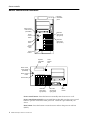
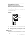


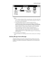
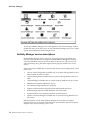


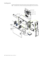


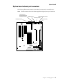
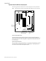
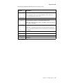
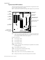


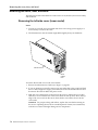
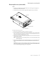

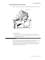
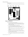
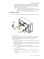

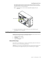
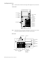

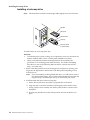

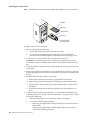
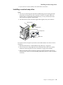

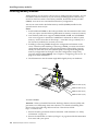
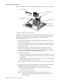


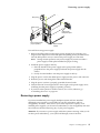
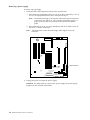
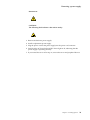

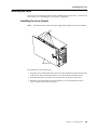
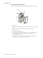
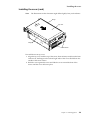
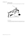
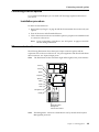

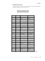

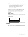

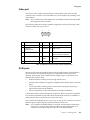

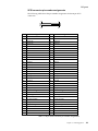

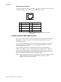
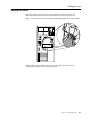
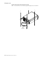
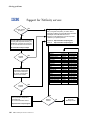
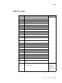
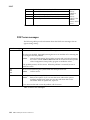

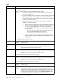
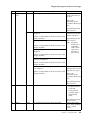

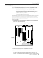
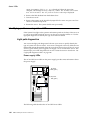
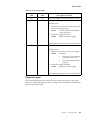

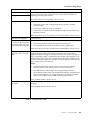

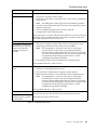
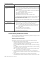

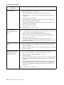


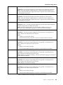
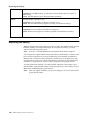
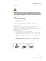

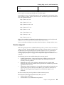


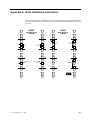


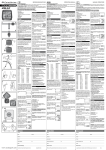
![[de] Gebrauchs- und Montageanleitung 2 [en](http://vs1.manualzilla.com/store/data/006783152_1-e861900a3fcaa918e4b3ee2089db558b-150x150.png)