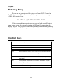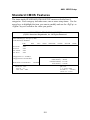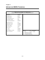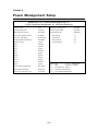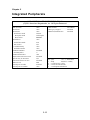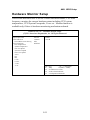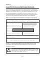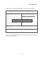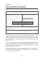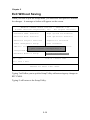
1
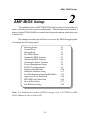
AMI® BIOS Setup Chapter 2. AMI® ® AMI BIOS BIOS SetupSetup The mainboard uses AMI® BIOS ROM that provides a Setup utility for users to modify the basic system configuration. The information is stored in a battery-backed CMOS RAM so it retains the Setup information when the power is turned off. This chapter provides you with the overview of the BIOS Setup program. It contains the following topics: Entering Setup Control Keys Getting Help The Main Menu Standard CMOS Features Advanced BIOS Features Advanced Chipset Features Power Management Setup PNP/PCI Configurations Integrated Peripherals Hardware Monitor Setup Load Performance/Optimized Defaults Supervisor/User Password IDE HDD Auto Detection Save & Exit Setup Exit Without Saving 2-2 2-2 2-3 2-4 2-5 2-6 2-7 2-8 2-9 2-10 2-11 2-12 2-14 2-16 2-17 2-18 Note: For detailed description of BIOS settings, refer to K7T266 Pro (MS6380) Manual in the provided CD. 2-1 Chapter 2 Entering Setup Power on the computer and the system will start POST (Power On Self Test) process. When the message below appears on the screen, press <DEL> key to enter Setup. Hit DEL if you want to run SETUP If the message disappears before you respond and you still wish to enter Setup, restart the system by turning it OFF and On or pressing the RESET button. You may also restart the system by simultaneously pressing <Ctrl>, <Alt>, and <Delete> keys. Control Keys <↑> Move to the previous item <↓> Move to the next item <←> Move to the item in the left hand <→> Move to the item in the right hand <Enter> Select the item <Esc> Jumps to the Exit menu or returns to the main menu from a submenu <+/PU> Increase the numeric value or make changes <-/PD> Decrease the numeric value or make changes <F5> Restore the previous CMOS value from CMOS, only for Option Page Setup Menu <F6> Load the default CMOS value from Fail-Safe default table, only for Option Page Setup Menu <F7> Load Optimized defaults <F10> Save all the CMOS changes and exit 2-2 AMI® BIOS Setup Getting Help After entering the Setup utility, the first screen you see is the Main Menu. Main Menu The main menu displays the setup categories the BIOS supplies. You can use the arrow keys ( ↑↓ ) to select the item. The on-line description for the selected setup category is displayed on the bottom of the screen. Default Settings The BIOS setup program contains two kinds of default settings: the Optimized and Performance defaults (High System Performance). Optimized defaults provide optimum and stable performance settings for all devices and the system. (The default value described in the chapter usually refers to the Optimized defaults unless otherwise specified.) Performance defaults provide the best system performance but may affect the system stability. 2-3 Chapter 2 The Main Menu Once you enter AMIBIOS SIMPLE SETUP UTILITY, the Main Menu will appear on the screen. The Main Menu displays twelve configurable functions and two exit choices. Use arrow keys to move among the items and press <Enter> to enter the sub-menu. AMIBIOS SIMPLE SETUP UTILITY - VERSION 1.44 (C)2001 American Megatrends, Inc. All Rights Reserved Standard CMOS Features High System Performance Advanced BIOS Features Load Optimized Defaults Advanced Chipset Features Supervisor Password Power Management Setup User Password PNP/PCI Configurations IDE HDD AUTO Detection Integrated Peripherals Save & Exit Setup Hardware Monitor Setup Exit Without Saving ESC : Quit ↑ ↓ ← → : Select Item F10 : Save & Exit Time, Date, Hard Disk Type… 2-4 AMI® BIOS Setup Standard CMOS Features The items inside STANDARD CMOS SETUP menu are divided into 9 categories. Each category includes none, one or more setup items. Use the arrow keys to highlight the item you want to modify and use the <PgUp> or <PgDn> keys to switch to the value you prefer. AMIBIOS SETUP - STANDARD CMOS SETUP (C)2001 American Megatrends, Inc. All Rights Reserved Date (mm/dd/yyyy) : Tue Apr 17, 2001 Time (hh/mm/ss) : 00:00:00 TYPE Pri Master Pri Slave Sec Master Sec Slave SIZE CYLS HEAD PRECOMP LANDZ SECTOR MODE : Auto : Auto : Auto : Auto Floppy Drive A : 1.44 MB 3½ Floppy Drive B : Not Installed Boot Sector Virus Protection Base Memory Other Memory Extended Memory Total Memory Disabled Month: Jan - Dec Day: 01 - 31 Year: 1901 - 2099 : 640 Kb : 384 Kb : 127 Mb : 128 Mb ESC : Exit ↑ ↓ : Select Item PU/PD/+/- : Modify (Shift) F2 : Color 2-5 Chapter 2 Advanced BIOS Features AMIBIOS SETUP - BIOS FEATURES SETUP (C)2001 American Megatrends, Inc. All Rights Reserved Quick Boot 1st Boot Device 2nd Boot Device 3rd Boot Device Try Other Boot Devices Initial Display Mode S.M.A.R.T. for Hard Disks BootUp Num-Lock Floppy Drive Swap Floppy Drive Seek Primary Display Password Check Boot To OS/2 L1 Cache L2 Cache System BIOS Cacheable C000, 32k Shadow :Enabled :Floppy :IDE-0 :CDROM :Yes :BIOS :Disabled :On :Disabled :Disabled :VGA/EGA :Setup :No :Enabled :Enabled :Enabled :Cached ESC : Quit ↑↓←→ : Select Item F1 : Help PU/PD/+/- : Modify F5 : Load Previous Values F6 : Load Fail-Safe Defaults F7 : Load Optimized Defaults 2-6 AMI® BIOS Setup Advanced Chipset Features AMIBIOS SETUP - CHIPSET FEATURES SETUP (C)2001 American Megatrends, Inc. All Rights Reserved Configure SDRAM Timing by SDRAM Frequency SDRAM CAS# Latency SDRAM Bank Interleave SDRAM 1T Command AGP Mode AGP Comp. Driving Manual AGP Comp. Driving AGP Fast Write AGP Read Synchronization AGP Aperture Size AGP Master 1 W/S Write AGP Master 1 W/S Read PCI Master Read Caching Search for MDA Resources PCI Delay Transaction BIOS Protection :SPD :HCLK :2.5 :Disabled :Disabled :Auto :Auto :CB :Disabled :Disabled :64MB :Disabled :Disabled :Disabled :Yes :Disabled :Enabled ESC : Quit ↑↓←→ : Select Item F1 : Help PU/PD/+/- : Modify F5 : Load Previous Values F6 : Load Fail-Safe Defaults F7 : Load Optimized Defaults !Note: Change these settings only if you are familiar with the chipset. 2-7 Chapter 2 Power Management Setup AMIBIOS SETUP - POWER MANAGEMENT SETUP (C)2001 American Megatrends, Inc. All Rights Reserved IPCA Function ACPI Standby State USB Wakeup From S3 Power Management/APM Green PC LED Status Suspend Time Out (Minute) Display Activity IRQ3 IRQ4 IRQ5 IRQ7 IRQ9 IRQ10 IRQ11 IRQ13 IRQ14 IRQ15 CPU Critical Temperature Power Button Function Restore on AC/Power Loss :Yes :S1/POS :Disabled :Enabled :Dual Color :Disabled :Ignore :Monitor :Monitor :Ignore :Monitor :Ignore :Ignore :Ignore :Ignore :Monitor :Ignore :Disabled :Suspend :Last State Wake Up On Ring/LAN Wake Up On PME# Resume By Alarm Alarm Date Alarm Hour Alarm Minute Alarm Second :Enabled :Enabled :Disabled :15 :12 :30 :30 ESC : Quit ↑↓←→ : Select Item F1 : Help PU/PD/+/- : Modify F5 : Load Previous Values F6 : Load Fail-Safe Defaults F7 : Load Optimized Defaults 2-8 AMI® BIOS Setup PNP/PCI Configurations This section describes configuring the PCI bus system and PnP (Plug & Play) feature. PCI, or Personal Computer Interconnect, is a system which allows I/O devices to operate at speeds nearing the speed the CPU itself uses when communicating with its special components. This section covers some very technical items and it is strongly recommended that only experienced users should make any changes to the default settings. AMIBIOS SETUP - PNP/PCI CONFIGURATION (C)2001 American Megatrends, Inc. All Rights Reserved Plug and Play Aware O/S Clear NVRAM Primary Graphics Adapter DMA Channel 0 DMA Channel 1 DMA Channel 3 DMA Channel 5 DMA Channel 6 DMA Channel 7 IRQ3 IRQ4 IRQ5 IRQ7 IRQ9 IRQ10 IRQ11 IRQ14 :No :No :PCI :PnP :PnP :PnP :PnP :PnP :PnP :PCI/PnP :PCI/PnP :PCI/PnP :PCI/PnP :PCI/PnP :PCI/PnP :PCI/PnP :PCI/PnP IRQ15 :PCI/PnP ESC : Quit ↑↓←→ : Select Item F1 : Help PU/PD/+/- : Modify F5 : Load Previous Values F6 : Load Fail-Safe Defaults F7 : Load Optimized Defaults 2-9 Chapter 2 Integrated Peripherals AMIBIOS SETUP - INTEGRATED PERIPHERALS (C)2001 American Megatrends, Inc. All Rights Reserved FDC Function Serial Port1 Serial Port2 Serial Port2 Mode IR Duplex Mode IR Pin Select Parallel Port Parallel Port Mode EPP Version Parallel Port IRQ Parallel Port DMA OnBoard Midi Port Midi IRQ Select OnBoard Game Port Keyboard PowerOn Function Specific Key for PowerOn Mouse PowerOn Function IDE Function OnChip AC97 Audio OnChip MC97 Modem :Auto :Auto :Auto :Normal :Half Duplex :IRRX/IRTX :Auto :ECP :N/A :Auto :Auto :Disabled :5 :200 :Disabled :N/A :Disabled :Both :Enabled :Auto 2-10 USB Controller USB Legacy Support USB Port 64/60 Emulation :All USB Port :Disabled :Disabled ESC : Quit ↑↓←→ : Select Item F1 : Help PU/PD/+/- : Modify F5 : Load Previous Values F6 : Load Fail-Safe Defaults F7 : Load Optimized Defaults AMI® BIOS Setup Hardware Monitor Setup This section describes how to set the Chassis Intrusion feature, CPU FSB frequency, monitor the current hardware status including CPU/system temperatures, CPU/System Fan speeds, Vcore etc. Monitor function is available only if there is hardware monitoring mechanism onboard. AMIBIOS SETUP - Hardware Monitor Setup (C)2001 American Megatrends, Inc. All Rights Reserved Spread Spectrum CPU FSB Clock CPU FSB/PCI Overclocking Chassis Intrusion CPU Temperature System Temperature CPU Fan Speed System Fan Speed Power Fan Speed Vcore VTT VIO + 5.0V +12.0V -12.0V - 5.0V ±0.25% 100MHz H/W Disabled Battery +5V SB ESC : Quit ↑↓←→ : Select Item F1 : Help PU/PD/+/- : Modify F5 : Load Previous Values F6 : Load Fail-Safe Defaults F7 : Load Optimized Defaults 2-11 Chapter 2 Load Performance/Optimized Defaults The two options on the main menu allow users to restore all of the BIOS settings to the default Performance or Optimized defaults. The Performance Defaults are the default values set by the mainboard manufacturer for the best system performance but probably will cause a stability issue. The Optimized Defaults are the default values also set by the mainboard manufacturer for both optimized and stable performance of the mainboard. When you select High System Performance, a message as below appears: AMIBIOS SIMPLE SETUP UTILITY - VERSION 1.44 (C)2001 American Megatrends, Inc. All Rights Reserved Standard CMOS Features High System Performance Advanced BIOS Features Load Optimized Defaults Advanced Chipset Features Supervisor Password User Password Power Management Setup Load Performance Defaults (Y/N)? N IDE HDD AUTO Detection PNP/PCI Configurations Integrated Peripherals Save & Exit Setup Hardware Monitor Setup Exit Without Saving ↑ ↓ ← → : Select Item ESC : Quit F10 : Save & Exit After enabling this item failed, please clear CMOS Pressing Y loads the default BIOS values that enable the best system performance (better than the Optimized Defaults) but may result in the instability of system. ! WARNING! The option is for powerful or overclocking users only. If the system crashes or hangs after enabling the feature, please CLEAR CMOS DATA to resolve the problem. For more information, refer to Clear CMOS Jumper:JBAT1 on page 1-5. 2-12 AMI® BIOS Setup When you select Load Optimized Defaults, a message as below appears: AMIBIOS SIMPLE SETUP UTILITY - VERSION 1.44 (C)2001 American Megatrends, Inc. All Rights Reserved Standard CMOS Features High System Performance Advanced BIOS Features Load Optimized Defaults Advanced Chipset Features Supervisor Password User Password Power Management Setup Load Optimized Defaults (Y/N)? N IDE HDD AUTO Detection PNP/PCI Configurations Integrated Peripherals Save & Exit Setup Hardware Monitor Setup Exit Without Saving ESC : Quit ↑ ↓ ← → : Select Item F10 : Save & Exit Load Optimized Defaults except Standard CMOS SETUP Pressing Y loads the default values that are factory settings for optimal and stable system performance. 2-13 Chapter 2 Supervisor/User Password When you select this function, a message as below will appear on the screen: AMIBIOS SIMPLE SETUP UTILITY - VERSION 1.44 (C)2001 American Megatrends, Inc. All Rights Reserved Standard CMOS Features High System Performance Advanced BIOS Features Load Optimized Defaults Advanced Chipset Features Supervisor Password Power Management Setup User Password IDE HDD AUTO Detection PNP/PCI Configurations Enter new supervisor password: Save & Exit Setup Integrated Peripherals Hardware Monitor Setup ESC : Quit Exit Without Saving ↑ ↓ ← → : Select Item F10 : Save & Exit Change/Set/Disable Password Type the password, up to six characters in length, and press <Enter>. The password typed now will clear any previously set password from CMOS memory. You will be prompted to confirm the password. Retype the password and press <Enter>. You may also press <Esc> to abort the selection and not enter a password. To clear a set password, just press <Enter> when you are prompted to enter the password. A message will show up confirming the password will be disabled. Once the password is disabled, the system will boot and you can enter Setup without entering any password. When a password has been set, you will be prompted to enter it every time you try to enter Setup. This prevents an unauthorized person from changing any part of your system configuration. 2-14 AMI® BIOS Setup Additionally, when a password is enabled, you can also have AMIBIOS to request a password each time the system is booted. This would prevent unauthorized use of your computer. The setting to determine when the password prompt is required is the PASSWORD CHECK option of the BIOS FEATURES SETUP menu. If the PASSWORD CHECK option is set to Always, the password is required both at boot and at entry to Setup. If set to Setup, password prompt only occurs when you try to enter Setup. About Supervisor Password & User Password: Supervisor password : Can enter and change the settings of the setup menu. User password: Can only enter but do not have the right to change the settings of the setup menu. 2-15 Chapter 2 IDE HDD AUTO Detection You can use this utility to AUTOMATICALLY detect the characteristics of most hard drives. AMIBIOS SETUP - STANDARD CMOS SETUP (C)2001 American Megatrends, Inc. All Rights Reserved Date (mm/dd/yyyy) : Tue Apr 17, 2001 Time (hh/mm/ss) : 00:00:00 TYPE Pri Master Pri Slave Sec Master Sec Slave SIZE CYLS HEAD PRECOMP LANDZ SECTOR MODE : Auto : Auto : Auto : Auto Floppy Drive A : 1.44 MB 3½ Floppy Drive B : Not Installed Boot Sector Virus Protection Base Memory Other Memory Extended Memory Total Memory Disabled : 640 Kb : 384 Kb : 127 Mb : 128 Mb ESC : Exit ↑ ↓ : Select Item PU/PD/+/- : Modify (Shift) F2 : Color Detecting drive parameters: Press ESC to abort 2-16 AMI® BIOS Setup Save & Exit Setup When you want to quit the Setup menu, you can select this option to save the changes and quit. A message as below will appear on the screen. AMIBIOS SIMPLE SETUP UTILITY - VERSION 1.44 (C)2001 American Megatrends, Inc. All Rights Reserved Standard CMOS Features High System Performance Advanced BIOS Features Load Optimized Defaults Advanced Chipset Features Supervisor Password Power Management Setup User Password IDE HDD AUTO Detection PNP/PCI Configurations SAVE to CMOS and EXIT(Y/N)? Y Save & Exit Setup Integrated Peripherals Exit Without Saving Hardware Monitor Setup ESC : Quit ↑ ↓ ← → : Select Item F10 : Save & Exit Save Data to CMOS & Exit SETUP Typing Y will allow you to quit the Setup Utility and save the user setup changes to RTC CMOS. Typing N will return to the Setup Utility. 2-17 Chapter 2 Exit Without Saving When you want to quit the Setup menu, you can select this option to abandon the changes. A message as below will appear on the screen. AMIBIOS SIMPLE SETUP UTILITY - VERSION 1.44 (C)2001 American Megatrends, Inc. All Rights Reserved Standard CMOS Features High System Performance Advanced BIOS Features Load Optimized Defaults Advanced Chipset Features Supervisor Password Power Management Setup User Password IDE HDD AUTO Detection PNP/PCI Configurations Quit without saving(Y/N)? N Save & Exit Setup Integrated Peripherals Exit Without Saving Hardware Monitor Setup ESC : Quit ↑ ↓ ← → : Select Item F10 : Save & Exit Abandon all Datas & Exit SETUP Typing Y will allow you to quit the Setup Utility without saving any changes to RTC CMOS. Typing N will return to the Setup Utility. 2-18