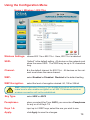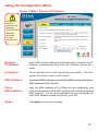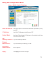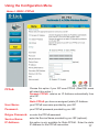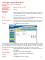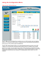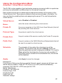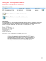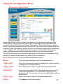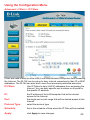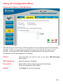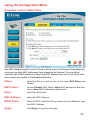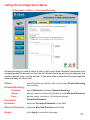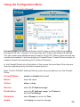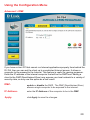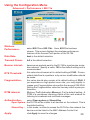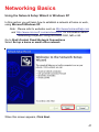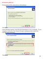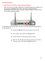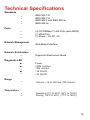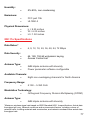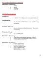
1
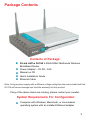
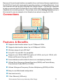
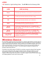
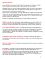
D-LINK AirPro DI-764
2.4 GHz / 5 GHz Multimode
Wireless Broadband Router
Manual
Building Networks for People
Contents
Package Contents ................................................................................3
Introduction .......................................................................................... 4
Wireless Basics ....................................................................................6
Getting Started ................................................................................... 10
Using the Configuration Menu ............................................................ 12
Networking Basics .............................................................................. 41
Troubleshooting .................................................................................. 70
Technical Specifications ..................................................................... 76
Contacting Technical Support............................................................. 79
Warranty and Registration .................................................................. 80
2
Package Contents
Contents of Package:
! D-Link AirPro DI-764 2.4GHz/5GHz Multimode Wireless
!
!
!
!
Broadband Router
Power Adapter – 5V DC, 3.0A
Manual on CD
Quick Installation Guide
Ethernet Cable
Note: Using a power supply with a different voltage rating than the one included with the
DI-764 will cause damage and void the warranty for this product.
If any of the above items are missing, please contact your reseller.
System Requirements For Configuration:
! Computer with Windows, Macintosh, or Linux-based
operating system with an installed Ethernet adapter
3
Introduction
D-Link, a leader in wireless technology, introduces the first integrated
multimode 2.4GHz/5GHz wireless broadband router, as part of the high
performance D-Link AirPro series of wireless networking products.
The new D-Link AirPro DI-764 Multimode Wireless Broadband Router is a
next generation multimode broadband router that simultaneously serves
both 802.11a wireless networks at 54 Mbps* (72 Mbps in Turbo mode*) and
802.11b wireless networks at 11Mbps (22 Mbps with D-Link AirPlus
products.) Featuring a breakthrough all-in-one dual band design that
delivers future investment protection with the promise of a superior product
life cycle and lower total cost of ownership, it is the ideal solution for present
and future Wireless Local Area Networks (WLANs).
The DI-764 will automatically obtain an IP address and forward additional IP
addresses to multiple clients for a seamless Ethernet network connection
and shared Internet access.
At 54Mbps (up to 72Mbps in Turbo mode*) in the 5GHz frequency range and
a simultaneous 11 Mbps (up to 22 Mbps with D-Link AirPlus products) in the
2.4GHz frequency range, the D-Link AirPro DI-764 multimode broadband
router delivers the fastest standards-based wireless technology in the
industry. Based on WiFi technology, as well as IEEE 802.11a and 802.11b
standards compliant, this next-generation multimode wireless access point
provides excellent network interoperability.
Armed with powerful management and security capabilities, the D-Link Air
Pro DI-764 has an intuitive and secure web-based interface that is powered
by an embedded web server.
After completing the steps outlined in the Quick Installation Guide (included
in your package) not only will you have the ability to share information and
resources, but you will also be able to enjoy the freedom that wireless
networking delivers, at speeds capable of handling a video stream.
*Maximum wireless signal rate based on IEEE Standard 802.11a specifications. Actual data
throughput will vary. Network conditions and environmental factors, including volume of
network traffic, building materials and construction, and network overhead lower actual data
throughput rate.
*When used with other D-Link AirPro products.
4
Because of its web-based interface (accessible from most Internet browser applications),
the DI-764 will work with most popular operating systems, including Macintosh, Linux
and Windows, and can be easily integrated into a large network. This Manual is designed
to help you connect the DI-764 with the D-Link 2.4GHz AirPlus or 5GHz AirPro Wireless
Adapters into an existing network. Please take a look at the Getting Started section in
this manual to see an example of an Infrastructure network using the DI-764.
Connections
Pressing the
Reset Button
restores the
router to its
original factory
default settings.
LAN ports automatically
sense cable type when
connecting to Ethernetenabled computers.
The WAN port is the
connection for the
Ethernet cable to the
Cable or DSL modem
Receptor
for the
Power
Adapter
Features & Benefits
! Supports data transfer rates of up to 72 Mbps at 5GHz
! Supports data transfer rates of up to 22 Mbps at 2.4GHz
! Wireless range of up to 900 feet*
! Fully 802.11a and 802.11b compatible
! Supports up to 256-bit WEP Encryption at 2.4GHz, and up to 152-bit, with
Enhanced Dynamic Keying at 5 GHz
! Less interference with a total of eleven non-overlapping channels
! Utilizes Direct Sequence Spread Spectrum (DSSS) and Packet Binary
Convolutional Code (PBCC) at 2.4GHz
! Utilizes Orthogonal Frequency Division Multiplexing (OFDM) at 5GHz
! Easy-to-use Web-based configuration
! User level security
! 3 Year Warranty (USA only)
*Environmental Factors may Adversely Affect Range.
5
LEDS
LED stands for Light-Emitting Diode. The DI-764 has the following LEDs:
LED
Power
LED Activity
A steady light indicates a connection to a power source
M1
A solid light indicates that the DI-764 is ready
M2
A solid light indicates that the unit is defective
WAN
A solid light indicates connection on the WAN port.
This LED blinks during data transmission.
WLAN
802.11a
A solid light indicates that the 802.11a wireless segment is ready. The LED blinks during 802.11a wireless
data transmission.
WLAN
802.11b
A solid light indicates that the 802.11b wireless segment is ready (when the DWL-650+ is installed.) The
LED blinks during 802.11b wireless data transmission.
Local Network
(Ports 1-4)
A solid light indicates a connection, a blinking light
indicates data transmission to an Ethernet-enabled
computer on ports 1-4.
Wireless Basics
D-Link AirPro wireless products are based on industry standards to provide easy-touse and compatible high-speed wireless connectivity within your home, business or
public access wireless networks. Strictly adhering to the IEEE standard, the D-Link
AirPro wireless family of products will allow you to securely access the data you
want, when and where you want it. You will be able to enjoy the freedom that
wireless networking delivers.
A wireless local area network (WLAN) is a cellular computer network that transmits
and receives data with radio signals instead of wires. Wireless LANs are used
increasingly in both home and office environments, and public areas such as
airports, coffee shops and universities. Innovative ways to utilize WLAN technology
are helping people to work and communicate
6
Wireless Basics
more efficiently. Increased mobility and the absence of cabling and other
fixed infrastructure have proven to be beneficial for many users.
Wireless users can use the same applications they use on a wired network.
Wireless adapter cards used on laptop and desktop systems support the
same protocols as Ethernet adapter cards.
Under many circumstances, it may be desirable for mobile network devices
to link to a conventional Ethernet LAN in order to use servers, printers or an
Internet connection supplied through the wired LAN. A Wireless Router is a
device used to provide this link.
People use wireless LAN technology for many different purposes:
Mobility - Productivity increases when people have access to data in any
location within the operating range of the WLAN. Management decisions
based on real-time information can significantly improve worker efficiency.
Low Implementation Costs – WLANs (Wireless Local Area Networks)
are easy to set up, manage, change and relocate. Networks that frequently
change, both physically and logically, can benefit from WLANs ease of
implementation. WLANs can operate in locations where installation of wiring
may be impractical.
Installation Speed and Simplicity - Installing a wireless LAN system
can be fast and easy and can eliminate the need to pull cable through walls
and ceilings.
Network Expansion - Wireless technology allows the network to go where
wires cannot go.
Scalability – Wireless Local Area Networks (WLANs) can be configured in
a variety of topologies to meet the needs of specific applications and
installations. Configurations are easily changed and range from peer-to-peer
networks suitable for a small number of users to larger infrastructure
networks to accommodate hundreds or thousands of users, depending on
the number of wireless devices deployed.
7
Wireless Basics
The DI-764 is compatible with other D-Link AirPro 802.11a products, which
include:
♦ 5GHz Wireless Cardbus Adapters used with laptop computers
(DWL-A650)
♦ 5GHz Wireless PCI Adapters used with desktop computers
(DWL-A520)
The DI-764 is also compatible with the D-Link AirPlus 802.11b wireless family,
which includes:
♦
Enhanced 2.4GHz Wireless Cardbus Adapters used with laptop
computers (DWL-650+)
♦
Enhanced 2.4GHz Wireless PCI cards used with desktop computers
(DWL-520+)
Standards-Based Technology
The versatile DI-764 Multimode Wireless Broadband Router integrates both
802.11a and 802.11b standards into a single unit.
The IEEE 802.11a standard designates that devices may operate at an
optimal data rate of 54 Mbps (72 Mbps in proprietary Turbo mode.) This
means that in most environments, within the specified range of this device,
you will be able to transfer large files quickly or even watch a movie in
MPEG format over your network without noticeable delays. This technology
works by transmitting high-speed digital data over a radio wave utilizing
OFDM (Orthogonal Frequency Division Multiplexing) technology. OFDM
works by splitting the radio signal into multiple smaller sub-signals that are
then transmitted simultaneously at different frequencies to the receiver.
OFDM reduces the amount of crosstalk (interference) in signal
transmissions. D-Link AirPro 802.11a products will automatically sense the
best possible connection speed to ensure the greatest speed and range
possible.
Based on the IEEE 802.11b standard, the DI-764 is also interoperable with
existing compatible 2.4GHz wireless technology with data transfer speeds of
up to 22Mbps (with the D-Link AirPlus family of wireless devices,) as well as
standard 802.11b technology ( the D-Link Air family of wireless devices),
with speeds of up to 11Mbps.
8
Wireless Basics
Installation Considerations
The D-Link AirPro DI-764 lets you access your network, using a wireless
connection, from virtually anywhere. Keep in mind, however, that the
number, thickness and location of walls, ceilings or other objects that the
wireless signals must pass through may limit the range. Typical ranges vary
depending on the types of materials and background RF (radio frequency)
noise in your home or business. The key to maximizing wireless range is to
follow these basic guidelines:
1. Keep the number of walls and ceilings between the DI-764 and your
receiving device (e.g., the DWL-A650 or the DWL-650+) to a minimum each wall or ceiling can reduce your D-Link AirPro Wireless product’s
range from 3-90 feet (1-30 meters.) Position your receiving devices so
that the number of walls or ceilings is minimized.
2. Be aware of the direct line between routers and computers. A wall that is
1.5 feet thick (.5 meters), at a 45-degree angle appears to be almost 3 feet
(1 meter) thick. At a 2-degree angle it looks over 42 feet (14 meters) thick!
Try to make sure that devices are positioned so that the signal will travel
straight through a wall or ceiling for better reception.
3. Building Materials make a difference - a solid metal door or aluminum
studs may have a negative effect on range. Try to position wireless
devices and computers with wireless adapters so that the signal passes
through drywall or open doorways and not other materials.
4. Keep your product away (at least 3-6 feet or 1-2 meters) from electrical
devices or appliances that generate RF noise.
9
Getting Started
Right out of the box, with its default settings, the DI-764 will
connect with other D-Link Air, AirPlus or AirPro products.
With a single IP Address from your Broadband Internet Service provider you
can share the Internet with all the computers on your local network, without
sacrificing speed or security, using D-Link Air networking products.
IP ADDRESS
Note: If you are using a DHCP-capable router in your network setup,
such as the DI-764, you will not need to assign a static IP Address.
If you need to assign IP Addresses to the computers on the network,
please remember that the IP Address for each computer must be in
the same IP Address range as all the computers in the network, and
the Subnet mask must be exactly the same for all the computers in the
network.
For example: If the first computer is assigned an IP Address of
192.168.0.2 with a Subnet Mask of 255.255.255.0, then the second
computer can be assigned an IP Address of 192.168.0.3 with a Subnet
Mask of 255.255.255.0, etc.
IMPORTANT: If computers or other devices are assigned the same
IP Address, one or more of the devices may not be visible on the
network.
An Infrastructure wireless network contains an Access Point. The
Infrastructure Network example, shown here, contains the following D-Link
network devices:
A wireless Broadband Router - D-Link AirPro DI-764
A laptop computer with a wireless adapter - D-Link AirPro DWL-A650 or
AirPlus DWL-650+
A desktop computer with a wireless adapter - D-Link AirPro DWL-A520 or
AirPlus DWL-520+
A Cable modem - D-Link DCM-200
10
Getting Started
1
2
4
3
5
Please remember that D-Link AirPro wireless devices are pre-configured to connect
together, right out of the box, with the default settings.
For a typical wireless setup at home (as shown above), please do the
following:
You will need broadband Internet access (Cable/DSL) subscription
Consult with your Cable/DSL provider for proper installation of the modem
Connect the modem to the DI-764 multimode wireless broadband router
(see the Quick Installation Guide included with the DI-764.)
If you are connecting a desktop computer to your network, you can install the
D-Link AirPro DWL-A520 (or the DWL-520+) wireless PCI adapter into an
available PCI slot. (See the Quick Installation Guide included with the DWLA520 or the DWL-520+.)
If you are connecting a laptop computer to your network, install the drivers for the
wireless cardbus adapter (D-Link AirPro DWL-A650) into a laptop computer .
(See the Quick Installation Guide included with DWL-A650 or DWL-650+.)
11
Using the Configuration Menu
Whenever you want to configure your network or the DI-764, you can access the
Configuration Menu by opening the web-browser and typing in the IP Address of the
DI-764. The DI-764 default IP Address is shown below:
!
Open the web browser
!
Type in the IP Address of
the Access Point
http://192.168.0.1
Note: if you have changed the default IP Address assigned to the DI-764, make sure to
enter the correct IP Address.
!
!
!
Type admin in the User
Name field
Leave the Password
blank
Click Next
Connect to 192.168.0.1
admin
The Home>Wizard screen will appear. Please refer to the Quick Installation
Guide for more information regarding the Setup Wizard.
Home > Wizard
12
Using the Configuration Menu
Home > Wireless > 802.11a
Wireless Settings- choose 802.11a or 802.11b+. Here, 802.11a is selected.
SSID-
“default” is the default setting. All devices on the network must
share the same SSID. If you change the default setting, the
SSID may be up to 32 characters long.
Channel-
52 is the default channel for 802.11a. All devices on the network must share the same channel.
Turbo Mode-
select ON or OFF. The default setting is OFF.
If you enable Turbo mode on the DI-764, make sure to also enable Turbo
mode on all 802.11a wireless clients or a wireless connection will not be
established.
WEPWEP Encryption-
select Enabled or Disabled. Disabled is the default setting.
select the level of encryption desired: 64, 128 or 152-bit
WEP (Wired Equivalent Privacy) If you enable encryption on the DI-764
make sure to also enable encryption on all 802.11a wireless clients or
wireless connection will not be established.
Key Type-
select HEX or ASCII
Hexadecimal digits consist of the numbers 0-9 and the letters A-F
ASCII (American Standard Code for Information Interchange) is a code for
representing English letters as numbers from 0-127
input up to 4 WEP keys; select the one you wish to use.
Keys 1-4-
Apply-
click Apply to save the changes.
13
Using the Configuration Menu
Home > Wireless > 802.11b+
Wireless Settings- choose 802.11a or 802.11b+. Here, 802.11b+ is selected.
SSID-
“default” is the default setting. All devices on the network must
share the same SSID. The SSID may be up to 32 characters
long.
Channel-
6 is the default channel for 802.11b+. All devices on the network must share the same channel.
WEP-
select Enabled or Disabled. Disabled is the default setting.
WEP Encryption-
select the level of encryption desired: 64, 128 or 256-bit
WEP (Wired Equivalent Privacy) If you enable encryption on the DI-764
make sure to also enable encryption on all 802.11b wireless clients or
wireless connection will not be established.
Key Type-
select HEX or ASCII
Passphrase-
when you select Key Type: ASCII, you can enter a Passphrase
for any or all of Keys 1-4
Keys 1-4-
input up to 4 WEP keys; select the one you wish to use.
Apply-
click Apply to save the changes.
14
Using the Configuration Menu
Home > WAN > Dynamic IP Address
Please be
sure to
remove any
existing
PPPoE client
software
installed
on your
computers.
Dynamic
IP Address-
most Cable modem users will select this option to obtain an IP
Address automatically from their ISP (Internet Service Provider).
Host Name-
this is optional, but may be required by some ISPs. The host
name is the device name of the Router.
MAC Address-
the default MAC Address is set to the WAN’s physical interface
MAC address on the Router.
Clone
MAC Address-
copy the MAC address of the Ethernet card installed by your
ISP, and replace the WAN MAC address with this Ethernet card
MAC address. It is not recommended that you change the default MAC address unless required by your ISP.
Apply-
click Apply to save the changes.
15
Using the Configuration Menu
Home > WAN > Static IP Address
Static IP Address- select this option to set static IP information provided to you by
your ISP.
IP Address-
input the IP Address provided by your ISP
Subnet Mask-
input your Subnet mask. (All devices in the network must have
the same subnet mask.)
ISP
Gateway Address- input the Gateway address
Primary
DNS Address-
input the address provided by your ISP
Secondary
DNS Address-
this is optional
Apply-
click Apply to save the changes.
16
Using the Configuration Menu
Home > WAN > PPPoE
PPPoE-
Choose this option if your ISP uses PPPoE. (Most DSL users
will select this option.)
Dynamic PPPoE- receive an IP Address automatically from
your ISP.
or
Static PPPoE-you have an assigned (static) IP Address.
User Name-
your PPPoE username provided by your ISP.
Password-
your PPPoE password provided by your ISP.
Retype Password- re-enter the PPPoE password
Service Name-
enter the Service Name provided by your ISP (optional).
IP Address-
this option is only available for Static PPPoE. Enter the static
IP Address for the PPPoE connection.
17
Using the Configuration Menu
Home > WAN > PPPoE continued
Primary
DNS Addressget this info from your ISP
Secondary
optional
DNS AddressMaximum
Idle Time-
enter a maximum idle time during which internet connection is
maintained during inactivity. To disable this feature, enter zero
or enable Auto-reconnect.
MTU-
Maximum Transmission Unit-1472 is default-you may need to
change the MTU to conform with your ISP.
Auto-reconnect-
if enabled, the DI-764 will automatically connect to your ISP
after your system is restarted or if the connection is dropped.
Apply-
click Apply to save the changes.
Home > LAN
LAN is short for Local Area Network. This is considered your internal network. These
are the IP settings of the LAN interface for the DI-764. These settings may be referred
to as Private settings. You may change the LAN IP address if needed. The LAN IP
address is private to your internal network and cannot be seen on the Internet.
IP Address-
the IP address of the LAN interface. The default IP address is:
192.168.0.1
Subnet Mask-
the subnet mask of the LAN interface.
The default subnet mask is 255.255.255.0
Local
optional
Apply-
click Apply to save the changes.
18
Using the Configuration Menu
Home > DHCP
DHCP stands for Dynamic Host Control Protocol. The DI-764 has a built-in DHCP
server. The DHCP Server will automatically assign an IP address to the computers on
the LAN/private network. Be sure to set your computers to be DHCP clients by setting
their TCP/IP settings to “Obtain an IP Address Automatically.” When you turn your
computers on, they will automatically load the proper TCP/IP settings provided by the
DI-764. The DHCP Server will automatically allocate an unused IP address from the IP
address pool to the requesting computer. You must specify the starting and ending
address of the IP address pool.
DHCP Server-
select Enabled or Disabled
Starting
IP Address-
the starting IP address for the DHCP server’s IP assignment
Ending
IP Address-
the ending IP address for the DHCP server’s IP assignment
Lease Time-
enter the Lease time
Apply-
click Apply to save the changes
19
Using the Configuration Menu
Advanced > Virtual Server
The DI-764 can be configured as a virtual server so that remote users accessing
Web or FTP services via the public IP address can be automatically redirected to
local servers in the LAN (Local Area Network).
The DI-764 firewall feature filters out unrecognized packets to protect your LAN
network so all computers networked with the DI-764 are invisible to the outside
world. If you wish, you can make some of the LAN computers accessible from the
Internet by enabling Virtual Server. Depending on the requested service, the DI-764
redirects the external service request to the appropriate server within the LAN
network.
20
Using the Configuration Menu
Advanced > Virtual Server continued
The DI-764 is also capable of port-redirection meaning incoming traffic to a particular
port may be redirected to a different port on the server computer.
Each virtual service that is created will be listed at the bottom of the screen in the
Virtual Servers List. There are pre-defined virtual services already in the table. You
may use them by enabling them and assigning the server IP to use that particular
virtual service.
Virtual Server-
select Enabled or Disabled
Name-
enter the name referencing the virtual service
Private IP-
the server computer in the LAN (Local Area Network) that will
be providing the virtual services.
Protocol Type-
the protocol used for the virtual service
Private Port-
the port number of the service used by the Private IP computer
Public Port-
the port number on the WAN (Wide Area Network)side that will
be used to access the virtual service.
Schedule-
The schedule of time when the virtual service will be
enabled. The schedule may be set to Always, which will
allow the particular service to always be enabled. If it is set to
Time, select the time frame for the service to be enabled. If
the system time is outside of the scheduled time, the service
will be disabled.
Apply-
click Apply to save the changes.
Example #1:
If you have a Web server that you wanted Internet users to access at all times, you
would need to enable it. Web (HTTP) server is on LAN (Local Area Network)
computer 192.168.0.25. HTTP uses port 80, TCP.
Name: Web Server
Private IP: 192.168.0.25
Protocol Type: TCP
Private Port: 80
Public Port: 80
Schedule: always
21
Using the Configuration Menu
Advanced > Virtual Server continued
Click on this icon to edit the virtual service
Click on this icon to delete the virtual service
Example #2:
If you have an FTP server that you wanted Internet users to access by WAN port
2100 and only during the weekends, you would need to enable it as such. FTP
server is on LAN computer 192.168.0.30. FTP uses port 21, TCP.
Name: FTP Server
Private IP: 192.168.0.30
Protocol Type: TCP
Private Port: 21
Public Port: 2100
Schedule: From: 01:00AM to 01:00AM, Sat to Sun
All Internet users who want to access this FTP Server
must connect to it from port 2100. This is an example of
port redirection and can be useful in cases where there
are many of the same servers on the LAN network.
22
Using the Configuration Menu
Advanced > Applications
Some applications require multiple connections, such as Internet gaming, video
conferencing, Internet telephony and others. These applications have difficulties
working through NAT (Network Address Translation). Special Applications makes
some of these applications work with the DI-764. If you need to run applications that
require multiple connections, specify the port normally associated with an application
in the “Trigger Port” field, select the protocol type as TCP or UDP, then enter the
public ports associated with the trigger port to open them for inbound traffic.
The DI-764 provides some predefined applications in the table on the bottom of the
web page. Select the application you want to use and enable it.
Note! Only one PC can use each Special Application tunnel.
Name:
this is the name referencing the special application.
Trigger Port:
this is the port used to trigger the application. It can be either
a single port or a range of ports.
Trigger Type:
this is the protocol used to trigger the special application.
Public Port:
Public Type:
this is the port number on the WAN side that will be used to
access the application. You may define a single port or a
range of ports. You can use a comma to add multiple ports or
port ranges.
this is the protocol used for the special application.
Apply:
click Apply to save the changes
23
Using the Configuration Menu
Advanced > Filters > IP Filters
Filters are used to deny or allow LAN (Local Area Network) computers from accessing
the Internet. The DI-764 can be setup to deny internal computers by their IP or MAC
addresses. The DI-764 can also block users from accessing restricted web sites.
IP Filters
Use IP Filters to deny LAN IP addresses from accessing the
Internet. You can deny specific port numbers or all ports for
the specific IP address.
IP:
Port:
the IP address of the LAN computer that will be denied
access to the Internet.
the single port or port range that will be denied access to the
Internet.
Protocol Type:
select the protocol type
Schedule:
this is the schedule of time when the IP Filter will be enabled.
Apply:
click Apply to save changes.
24
Using the Configuration Menu
Advanced > Filters > URL Blocking
URL Blocking is used to deny LAN computers from accessing specific web sites by
its URL. A URL is a specially formatted text string that defines a location on the
Internet. If any part of the URL contains the blocked word, the site will not be
accessible and the web page will not display.
Filters-
select the filter you wish to use; in this case, URL Blocking
was chosen.
URL Blocking-
select Enabled or Disabled.
Keywords-
block URLs which contain keywords listed below.
Enter the keywords in this space.
Apply-
click Apply to save the changes.
25
Using the Configuration Menu
Advanced > Filters > MAC Filters
Use MAC (Media Access Control) Filters to allow or deny LAN (Local Area Network)
computers by their MAC addresses from accessing the Internet. You can either
manually add a MAC address or select the MAC address from the list of clients that
are currently connected to the Broadband Router.
Filters-
select the filter you wish to use; in this case, MAC filters was
chosen.
MAC Filters-
choose Disable MAC filters; allow MAC addresses listed below; or deny MAC addresses listed below.
Name-
enter the name here.
MAC Address-
enter the MAC Address.
DHCP Client-
select a DHCP client from the pull-down list; click Clone to copy
that MAC Address
Apply-
click Apply to save the changes.
26
Using the Configuration Menu
Advanced > Filters > Domain Blocking
Domain Blocking is used to allow or deny LAN (Local Area Network) computers from
accessing specific domains on the Internet. Domain blocking will deny all requests to a
specific domain such as http and ftp. It can also allow computers to access specific
sites and deny all other sites.
FiltersDomain Blocking:
select the filter you wish to use; in this case, Domain Blocking
was chosen.
Disabled-
select Disabled to disable Domain Blocking
Allow-
allows users to access all domains except Blocked Domains
denies users access to all domains except
Permitted Domains
Deny-
Permitted
Domains-
enter the Permitted Domains in this field
Blocked Domains- enter the Blocked Domains in this field
Apply-
click Apply to save the changes.
27
Using the Configuration Menu
Advanced > Firewall
Firewall Rules is an advanced feature used to deny or allow traffic from passing
through the DI-764. It works in the same way as IP Filters with additional settings.
You can create more detailed access rules for the DI-764. When virtual services are
created and enabled, it will also display in Firewall Rules. Firewall Rules contains all
network firewall rules pertaining to IP (Internet Protocol).
In the Firewall Rules List at the bottom of the screen, the priorities of the rules are
from top (highest priority) to bottom (lowest priority.)
Note: The DI-764 MAC Address filtering rules have precedence over the Firewall
Rules.
Firewall Rules-
enable or disable theFirewall
Name-
enter the name
Action-
allow or deny
Source-
enter the IP Address range
Destination-
enter the IP Address range; the Protocol;
and the Port Range
Schedule-
select Always or enter the Time.
Apply-
click Apply to save the changes.
28
Using the Configuration Menu
Advanced > DMZ
If you have a client PC that cannot run Internet applications properly from behind the
DI-764, then you can set the client up to unrestricted Internet access. It allows a
computer to be exposed to the Internet. This feature is useful for gaming purposes.
Enter the IP address of the internal computer that will be the DMZ host. Adding a
client to the DMZ (Demilitarized Zone) may expose your local network to a variety of
security risks, so only use this option as a last resort.
DMZ-
enable or disable the DMZ. The DMZ (Demilitarized Zone)
allows a single computer to be exposed to the internet.
IP Address-
enter the IP Address of the computer to be in the DMZ
Apply-
click Apply to save the changes.
29
Using the Configuration Menu
Advanced > Performance > 802.11a
Wireless
Performance-
select 802.11a or 802.11b+. Here, 802.11a has been
chosen. This screen displays the wireless performance
features of the Access Point portion of the DI-764.
Data Rate-
best is the default selection
Transmit Power-
full is the default selection.
Beacon interval-
beacons are packets sent by the DI-764 to synchronize a wireless network. Specify a value. 100 is the default setting and is
recommended.
RTS Threshold-
this value should remain at its default setting of 2342. If inconsistent data flow is a problem, only a minor modification should
be made.
Fragmentation-
this value should also remain at its default setting of 2346. If
you experience a high packet error rate, you may slightly increase your Fragmentation value within the range of 256-2346.
Setting the Fragmentation value too low may result in poor performance.
DTIM interval-
(Delivery Traffic Indication Message) 1 is the default setting. A
DTIM is a countdown informing clients of the next window for
listening to broadcast and multicast messages.
select Open system or Shared Key
Open System - the DI-764 will be visible to all devices on the network. This is
the default setting
Shared Key - in this mode, in order to access the DI-764 on the network, the
device must be listed in the MAC Address Control List
Authentication-
Apply-
click Apply to save the changes
30
Using the Configuration Menu
Advanced > Performance > 802.11b+
Wireless
Performance-
Select 802.11a or 802.11b+. 802.11b+ is selected here. Displayed in this window are the Wireless Performance features
for the Access Point portion of the DI-764.
Beacon interval-
beacons are packets sent by the DI-764 to synchronize a wireless network. Specify a value. 100 is the default setting and is
recommended.
RTS Threshold-
this value should remain at its default setting of 2342. If inconsistent data flow is a problem, only a minor modification should
be made.
Fragmentation-
this value should also remain at its default setting of 2346. If
you experience a high packet error rate, you may slightly increase your Fragmentation value within the range of 256-2346.
Setting the Fragmentation value too low may result in poor performance.
DTIM interval-
(Delivery Traffic Indication Message) 3 is the default setting. A
DTIM is a countdown informing clients of the next window for
listening to broadcast and multicast messages.
Basic Rates-
choose from1-2Mbps; 1,2,5.5,11 Mbps; or 1,2,5.5,11,22 Mbps
TX Rates-
select the basic transfer rates based on the speed of the wireless adapters on the WLAN (wireless local area network);
choose from among the same ranges as those listed in the Basic
Rates,above.
31
Using the Configuration Menu
Preamble Type-
select Short or Long Preamble. The Preamble Type defines
the length of the CRC (Cyclic Redundancy Check) block for
communication between the DI-764 and roaming wireless adapters. Make sure to select the appropriate preamble type and
click Apply. Note: High network traffic areas should use the
shorter preamble type. CRC is a common technique for detecting data transmission errors.
select Open system or Shared Key
Open System - the DI-764 will be visible to all devices on the network. This is
the default setting
Shared Key - in this mode, in order to access the DI-764 on the network, the
device must be listed in the MAC Address Control List
Authentication-
Apply-
click Apply to save changes
Tools> Admin
Administrator
Login Name
admin is the default login name for the Admin account
User
Login Name
user is the default login name for the User account
Admin Password-
the default setting is blank - no password. To change the password, enter and confirm the new password.
User Password-
the default setting is blank - no password. To change the password, enter and confirm the new password.
32
Using the Configuration Menu
Remote Management
Remote Management allows the DI-764 to be configured from the Internet by a web
browser. A username and password is still required to access the Web-Management
interface. In general, only a member of your network can browse the built-in web
pages to perform “Administrator” tasks. This feature enables you to perform
“Administrator” tasks from the remote (Internet) host.
IP Address: Internet IP address of the computer that has access to the Router. It is
not recommended that you set the IP address to * (star), because this allows any
Internet IP address to access the Router, which could result in a loss of security for
your network. If you elect to enable Remote Management, make sure to enter the
IP Address of the remote computer allowed to configure the DI-764.
Port: For security purposes, select a separate port number used to access the
Router. (The following is an example only; you may use a different port number.)
Example: http://x.x.x.x:8080 where x.x.x.x is the WAN IP address of the Router
and 8080 is the port used for the Web-Management interface.
Tools > Time
Time settings-
in this window you can choose the time zone; set the time;
and enable or disable Daylight Savings Time.
Default
NTP Server-
NTP is short for Network Time Protocol. NTP synchronizes computer clock times in a network of computers.
This field is optional.
33
Using the Configuration Menu
Tools > System
System Settings
Save Settings to
Local Hard Drive-
click Save to save the current settings to the local Hard Drive
Load Settings from
Local Hard Drive- click Browse to find the settings, then click Load
Restore to Factory
click Restore to restore the factory default settings
Default Settings-
34
Using the Configuration Menu
Tools > Firmware
Firmware Upgrade- click on the link in this screen to find out if there is an updated
firmware; if so, download the new firmware to your hard drive.
Browse-
after you have downloaded the new firmware, click Browse in
this window to locate the firmware update on your hard drive.
Click Apply to complete the firmware upgrade.
35
Using the Configuration Menu
Tools > Misc
Ping Test-
the Ping Test is used to send Ping packets to test if a computer
is on the Internet. Enter the IP Address that you wish to Ping,
and click Ping
Restart Device-
click Reboot to restart the DI-764
Block WAN Ping-
if you choose to block WAN Ping, the WAN IP Address of the
DI-764 will not respond to pings. Blocking the Ping may provide
some extra security from hackers.
Discard Ping
from WAN sideVPN
Pass Through-
click Enabled to block the WAN ping
the DI-764 supports VPN (Virtual Private Network) pass-through
for both PPTP (Point-to-Point Tunneling Protocol) and IPSec
(IP Security). Once VPN pass-through is enabled, there is no
need to open up virtual services. Multiple VPN connections
can be made through the DI-764. This is useful when you have
many VPN clients on the LAN network.
PPTP- select Enabled or Disabled
IPSec- select Enabled or Disabled
Apply-
click Apply to save changes
36
Using the Configuration Menu
Status > Device Info
Device Information- This screen displays information about the DI-764
37
Using the Configuration Menu
Status > Log
View Log-
this screen displays the activity on the DI-764
Log Settings-
for advanced features, click on Log Settings
38
Using the Configuration Menu
Status > Stats
Traffic Statistics-
displays the receive and transmit packets that are passing
through the DI-764. Click on Refresh or Reset, for the most
recent information.
Status > Wireless
Connected
Wireless
Client List-
displays the wireless clients that are connected
to the Access Point function of the DI-764.
39
Using the Configuration Menu
Help
Help-
displays the complete Help menu. For help at anytime, click
the Help tab in the Configuration menu.
40
Networking Basics
Using the Network Setup Wizard in Windows XP
In this section you will learn how to establish a network at home or work,
using Microsoft Windows XP.
Note: Please refer to websites such as http://www.homenethelp.com
and http://www.microsoft.com/windows2000 for information about
networking computers using Windows 2000, ME or 98.
Go to Start>Control Panel>Network Connections
Select Set up a home or small office network
When this screen appears, Click Next.
41
Networking Basics
Please follow all the instructions in this window:
Click Next
In the following window, select the best description of your computer. If your
computer connects to the internet through a gateway/router, select the
second option as shown.
Click Next
42
Networking Basics
Enter a Computer description and a Computer name (optional.)
Click Next
Enter a Workgroup name. All computers on your network should have the
same Workgroup name.
Click Next
43
Networking Basics
Please wait while the Network Setup Wizard applies the changes.
When the changes are complete, click Next.
Please wait while the Network Setup Wizard configures the computer.
This may take a few minutes.
44
Networking Basics
In the window below, select the option that fits your needs. In this example, Create
a Network Setup Disk has been selected. You will run this disk on each of the
computers on your network. Click Next.
Insert a disk into the Floppy Disk Drive, in this case drive A.
45
Networking Basics
Please read the information under Here’s how in the screen below. After you complete the Network Setup Wizard you will use the Network Setup Disk to run the
Network Setup Wizard once on each of the computers on your network. To continue
click Next.
46
Networking Basics
Please read the information on this screen, then click Finish to complete the
Network Setup Wizard.
The new settings will take effect when you restart the computer. Click Yes to
restart the computer.
You have completed configuring this computer. Next, you will need to run the
Network Setup Disk on all the other computers on your network. After running the Network Setup Disk on all your computers, your new wireless network will be ready to use.
47
Networking Basics
Naming your Computer
To name your computer, please follow these directions:In Windows XP:
! Click Start (in the lower left corner of the screen)
!
Right-click on My Computer
!
Select Properties and click
! Select the Computer
Name Tab in the System
Properties window.
! You may enter a Com-
puter Description if you
wish; this field is optional.
! To rename the computer
and join a domain, Click
Change.
48
Networking Basics
Naming your Computer
! In this window, enter the
Computer name
! Select Workgroup and enter
the name of the Workgroup
! All computers on your network
must have the same
Workgroup name.
! Click OK
Checking the IP Address in Windows XP
The wireless adapter-equipped computers in your network must be in the same IP
Address range (see Getting Started in this manual for a definition of IP Address Range.)
To check on the IP Address of the adapter, please do the following:
! Right-click on the
Local Area
Connection icon
in the task bar
! Click on Status
49
Networking Basics
Checking the IP Address in Windows XP
This window will appear.
!
Click the
Support tab
!
Click Close
Assigning a Static IP Address in Windows XP/2000
Note: Residential Gateways/Broadband Routers will automatically assign IP Addresses to the computers on the network, using DHCP (Dynamic Host Configuration Protocol) technology. If you are using a DHCP-capable Gateway/Router you
will not need to assign Static IP Addresses.
If you are not using a DHCP capable Gateway/Router, or you need to assign a Static IP
Address, please follow these instructions:
!
Go to Start
!
Double-click on
Control Panel
50
Networking Basics
Assigning a Static IP Address in Windows XP/2000
! Double-click on
Network
Connections
! Right-click on Local Area
Connections
! Double-click on
Properties
51
Networking Basics
Assigning a Static IP Address
in Windows XP/2000
! Click on Internet Protocol
(TCP/IP)
! Click Properties
!
Input your IP address and
subnet mask. (The IP
Addresses on your network
must be within the same
range. For example, if one
computer has an IP Address
of 192.168.0.2, the other
computers should have IP
Addresses that are
sequential, like 192.168.0.3
and 192.168.0.4. The
subnet mask must be the
same for all the computers
on the network.
! Enter the IP Address
of the Default
Gateway (in this case
it is 192.168.0.1 for
the DI-764)
! Input your DNS server
address.
The DNS server address will be supplied by your ISP (Internet Service Provider).
If the DNS Server address is not available from your ISP, you may input 192.168.0.1
in this field.
!
Click OK
52
Networking Basics
Assigning a Static IP Address with Macintosh OSX
! Go to the Apple Menu and select System Preferences
! cClick on Network
! Select Built-in Ethernet in the
Show pull-down menu
! Select Manually in the
Configure pull-down menu
! Input the Static IP Address,
the Subnet Mask and the
Router IP Address in the
appropriate fields
! Input the Domain Name
Server address. Your ISP
(Internet Service Provider)
will provide the IP address of
the DNS Server. If the DNS
Server address is not available from your ISP, you may
input 192.168.0.1 in this field.
! Click Apply Now
53
Networking Basics
Selecting a Dynamic IP Address with Macintosh OSX
! Go to the Apple Menu and select
System Preferences
! Click on Network
! Select Built-in Ethernet in the
Show pull-down menu
! Select Using DHCP in the
Configure pull-down menu
! Click Apply Now
! The IP Address, Subnet
mask, and the Router’s IP
Address will appear in a few
seconds
54
Networking Basics
Checking the Wireless Connection by Pinging in Windows XP and
2000
! Go to Start > Run >
type cmd. A window
similar to this one
will appear. Type
ping
xxx.xxx.xxx.xxx,
where xxx is the IP
Address of the
Wireless Router or
Access Point. A
good wireless
connection will show
four replies from the
Wireless Router or
Acess Point, as
shown.
Checking the Wireless Connection by Pinging in Windows Me
and 98
! Go to Start > Run
> type command.
A window similar to
this will appear.
Type ping
xxx.xxx.xxx.xxx
where xxx is the IP
Address of the
Wireless Router or
Access Point. A
good wireless
connection will
show four replies
from the wireless
router or access
point, as shown.
55
Networking Basics
Adding and Sharing Printers in Windows XP
After you have run the Network Setup Wizard on all the computers in your network
(please see the Network Setup Wizard section at the beginning of Networking
Basics,) you can use the Add Printer Wizard to add or share a printer on your
network.
Whether you want to add a local printer (a printer connected directly to one computer,)
share an LPR printer (a printer connected to a print server) or share a network
printer (a printer connected to your network through a Gateway/Router,) use the Add
Printer Wizard. Please follow the directions below:
First, make sure that you have run the Network Setup Wizard on all of the
computers on your network.
On the following pages, we will show you these 3 ways to use the Add Printer Wizard:
1. Adding a local printer
2. Sharing an network printer
3. Sharing an LPR printer
(Other Networking Tasks)
For help with other tasks, that we have not covered here, in home or small office
networking, see Using the Shared Documents folder and Sharing files and folders
in the Help and Support Center in Microsoft Windows XP.
56
Networking Basics
Adding a local printer (a printer connected directly to a computer)
A printer that is not shared on the network and is connected directly to one computer
is called a local printer. If you do not need to share your printer on a network,
follow these directions to add the printer to one computer.
! Go to
Start>
Printers
and Faxes
! Click on Add a printer
57
Networking Basics
Adding a local printer
! Click Next
! Select Local printer
attached to this
computer
! (Deselect Automati-
cally detect and install
my Plug and Play
printer if it has been
selected.)
! Click Next
! Select Use the
following port:
! From the pull-down
menu select the correct
port for your printer
(Most computers use the LPT1: port,
as shown in the illustration.)
! Click Next
58
Networking Basics
Adding a local printer
!
Select and highlight
the correct driver for
your printer.
! Click Next
(If the correct driver is
not displayed, insert the
CD or floppy disk that
came with your printer
and click Have Disk.)
! At this screen, you can
change the name of
the printer (optional.)
! Click Next
! Select Yes, to print a
test page. A successful
printing will confirm that
you have chosen the
correct driver.
!
Click Next
59
Networking Basics
Adding a local printer
This screen gives you information about your printer.
Click Finish
When the test page has printed,
Click OK
60
Networking Basics
Adding a local printer
! Go to Start> Printers
and Faxes
A successful installation will display
the printer icon as shown at right.
You have successfully added a local
printer.
Sharing a network printer
After you have run the Network Setup Wizard on all the computers on your network, you can run the Add Printer Wizard on all the computers on your network.
Please follow these directions to use the Add Printer Wizard to share a printer on
your network:
! Go to Start>
Printers and Faxes
61
Networking Basics
Sharing a network printer
! Click on
Add a printer
! Click Next
! Select
Network Printer
!
Click Next
62
Networking Basics
Sharing a network printer
! Select Browse for
a printer
! Click Next
Select the printer you
would like to share
! Click Next
! Click Finish
63
Networking Basics
Sharing a network printer
!
To check for proper
installation:
!
Go to Start > Printers
and Faxes
The printer icon will appear at right,
indicating proper installation.
You have completed adding the
printer.
To share this printer
on your network:
!
Remember the printer
name
!
Run the Add Printer
Wizard on all the
computers on your
network
!
Make sure you have
already run the
Network Setup
Wizard on all the
network computers
After you run the Add Printer
Wizard on all the computers in the
network, you can share the printer.
64
Networking Basics
Sharing an LPR printer
To share an LPR printer (using a print server,) you will need a Print Server such as
the DP-101P+. Please make sure that you have run the Network Setup Wizard on
all the computers on your network. To share an LPR printer, please follow these
directions:
! Go to Start >
Printers and
Faxes
! Click on Add
a Printer
The screen to the
right will appear
! Click Next
! Select
Local
Printer...
! Click Next
65
Networking Basics
Sharing an LPR printer
! Select Create a new port
! From the pull-down menu,
select Standard TCP/IP
Port, as shown.
! Click Next
! Please read the
instructions on this
screen
! Click Next
! Enter the Printer IP
Address and the Port
Name, as shown.
! Click Next
66
Networking Basics
Sharing an LPR printer
! In this
screen,
select
Custom
! Click
Settings
! Enter the Port
Name and the
Printer Name
or
IP Address.
! Select LPR
! Enter a
Queue Name
(if your PrintServer/
Gateway has
more than
one port, you
will need a
Queue
name.)
! Click OK
67
Networking Basics
Sharing an LPR printer
! This screen will show you
information about your
printer.
! Click Finish
! Select the printer you
are adding from the list
of Printers.
! Insert the printer driver disk
that came with your printer.
! Click Have Disk
If the printer driver is already installed,
do the following:
! Select Keep existing
driver
! Click Next
68
Networking Basics
Sharing an LPR printer
!
You can rename your printer if
you choose. It is optional.
!
Please remember the name of
your printer. You will need this
information when you use the
Add Printer Wizard on the
other computers on your
network.
!
Click Next
!
Select Yes, to print a test page.
!
Click Next
This screen will display information about your printer.
!
Click Finish to complete the
addition of the printer.
!
Please run the Add Printer
Wizard on all the computers
on your network in order to
share the printer.
Note: You must run the Network Setup Wizard on all the computers on your network before
you run the Add Printer Wizard.
69
Troubleshooting
This Chapter provides solutions to problems that can occur during the installation and
operation of the DI-764 Wireless Broadband Router. We cover various aspects of the
network setup, including the network adapters. Please read the following if you are
having problems.
Note: It is recommended that you use an Ethernet connection to
configure the DI-764 Wireless Broadband Router.
1.The computer used to configure the DI-764 cannot access the
Configuration menu.
! Check that the Ethernet LED on the DI-764 is ON. If the
LED is not ON, check that the cable for the Ethernet
connection is securely inserted.
! Check that the Ethernet Adapter is working properly. Please
see item 3 (Check that the drivers for the network
adapters are installed properly) in this Troubleshooting
section to check that the drivers are loaded properly.
! Check that the IP Address is in the same range and subnet
as the DI-764. Please see Checking the IP Address in
Windows XP in the Networking Basics section of this
manual.
Note: The IP Address of the DI-764 is 192.168.0.1. All the computers on the
network must have a unique IP Address in the same range, e.g., 192.168.0.x.
Any computers that have identical IP Addresses will not be visible on the
network. They must all have the same subnet mask, e.g., 255.255.255.0
! Do a Ping test to make sure that the DI-764 is responding.
Go to Start>Run>Type Command>Type ping 192.168.0.1.
A successful ping will show four replies.
Note: If you have
changed the default IP
Address, make sure to
ping the correct IP Address assigned to the
DI-764.
70
Troubleshooting
2. The wireless client cannot access the Internet in the
Infrastructure mode.
Make sure the wireless client is associated and joined with the correct Access
Point. To check this connection: Right-click on the Local Area Connection icon
in the taskbar> select View Available Wireless Networks. The Connect to
Wireless Network screen will appear. Please make sure you have selected the
correct available network, as shown in the illustrations below.
default
! Check that the IP Address assigned to the wireless adapter is within the
same IP Address range as the access point and gateway. (Since the
DI-764 has an IP Address of 192.168.0.1, wireless adapters must have
an IP Address in the same range, e.g., 192.168.0.x. Each device must
have a unique IP Address; no two devices may have the same IP
Address. The subnet mask must be the same for all the computers on
the network.) To check the IP Address assigned to the wireless
adapter, double-click on the Local Area Connection icon in the
taskbar > select the Support tab and the IP Address will be displayed.
(Please refer to Checking the IP Address in the Networking Basics
section of this manual.)
! If it is necessary to assign a Static IP Address to the wireless adapter,
please refer to the appropriate section in Networking Basics. If you are
entering a DNS Server address you must also enter the Default
Gateway Address. (Remember that if you have a DHCP-capable
router, you will not need to assign a Static IP Address. See
Networking Basics: Assigning a Static IP Address.)
71
Troubleshooting
3. Check that the drivers for the network adapters are
installed properly.
You may be using different network adapters than those illustrated here, but this
procedure will remain the same, regardless of the type of network adapters you are
using.
! Select the
Hardware
Tab
! Click Device
Manager
72
Troubleshooting
! Double-click
on Network
Adapters
! Right-click on D-Link
AirPro DWL-A650
Wireless Cardbus
Adapter
! Select Properties
to check that the
drivers are
installed properly
! Look under Device
Status to check that the
device is working
properly
! Click OK
73
Troubleshooting
4. What variables may cause my wireless products to lose reception?
D-Link products let you access your network from virtually anywhere you want.
However, the positioning of the products within your environment will affect the
wireless range. Please refer to Installation Considerations in the Wireless
Basics section of this manual for further information about the most advantageous placement of your D-Link wireless products.
5. Why does my wireless connection keep dropping?
! Antenna Orientation- Try different antenna orientations for the DI-764.
Try to keep the antenna at least 6 inches away from the wall or other
objects.
! If you are using 2.4GHz cordless phones, X-10 equipment or other home
security systems, ceiling fans, and lights, your wireless connection will
degrade dramatically or drop altogether. Try changing the Channel on
your Router, Access Point and Wireless adapter to a different Channel
to avoid interference.
! Keep your product away (at least 3-6 feet) from electrical devices that
generate RF noise, like microwaves, Monitors, electric motors, etc.
6. Why can’t I get a wireless connection?
To establish a wireless connection, while enabling Encryption on the DI-764,
you must also enable encryption on the wireless client.
! For 802.11a, the Encryption settings are: 64, 128 or 152 bit. Make sure
that the encryption bit level is the same on the Router and the Wireless
Client.
! For 802.11b, the Encryption settings are: 64, 128, or 256 bit. Make sure
that the encryption bit level is the same on the Router and the Wireless
Client.
Make sure that the SSID on the Router and the Wireless Client are exactly the
same. If they are not, wireless connection will not be established. Please note
that there are two separate SSIDs for 802.11a and 802.11b. The default SSID
for both 802.11a and 802.11b is default.
74
Troubleshooting
7. Resetting the DI-764 to Factory Default Settings
After you have tried other methods for troubleshooting your network, you
may choose to Reset the DI-764 to the factory default settings.
Remember that D-Link AirPro products network together, out of the box,
at the factory default settings.
To hard-reset the D-Link AirPro DI-764 to Factory Default Settings, please
do the following:
! Locate the Reset button on the back of the DI-764
! Use a paper clip to press the Reset button
! Hold for about 10 seconds and then release
! After the DI-764 reboots (this may take a few minutes)
it will be reset to the factory Default settings
75
Technical Specifications
Standards
•
•
•
•
IEEE 802.11b
IEEE 802.11a
IEEE 802.3 and IEEE 802.3u
IEEE 802.3x
•
•
•
(4) 10/100Base-T LAN Ports (auto-MDIX)
(1) WAN Port
(1) Power – 5V DC, 3A
Ports
Network Management
•
Web-Based Interface
Network Architecture
•
Supports Infrastructure Mode
..
.
Diagnostic LED
•
Power
100M Link/Act
10M Link/Act
11a WLAN
11b WLAN
•
Indoors – up to 328 feet (100 meters)
•
•
Operating: 0ºC to 40ºC (32ºF to 104ºF)
Storing: -25ºC to 60ºC (-77ºF to 140ºF)
•
Range
Temperature
76
Humidity:
Emissions:
•
5%-95%, non-condensing
•
•
FCC part 15b
UL1950-3
Physical Dimensions:
•
L = 9.25 inches
•
W = 6.25 inches
•
H = 1.50 inches
802.11a Specifications
Data Rates:*
•
6, 9, 12, 18, 24, 36, 48, 54, 72 Mbps
Data Security:
•
•
64, 128, 152-bit w/dynamic keying
Access Control List
Antenna Type:
•
•
5dBi dipole antenna with diversity
Power parameter software configurable
Available Channels:
•
Eight non-overlapping channels for North America
Frequency Range:
•
5.150 – 5.350 GHz
Modulation Technology:
•
Orthogonal Frequency Division Multiplexing (OFDM)
Antenna Type:
•
5dBi dipole antenna with diversity
*Maximum wireless signal rate based on IEEE Standard 802.11a specifications. Actual data
throughput will vary. Network conditions and environmental factors, including volume of
network traffic, building materials and construction, and network overhead lower actual data
throughput rate.
77
802.11a Specifications (continued)
Modulation Techniques:
•
BPSK
•
QPSK
•
16 QAM
•
64 QAM
802.11b Specifications
Data Rates:
•
Data Security:
•
1, 2, 5.5, 11, 22 Mbps (with Automatic Fallback)
64, 128, 256-bit WEP (Wired Equivalent Privacy)
Encryption
Available Channels:
•
Eleven channels for North America. Three nonoverlapping.
Frequency Range:
•
2.4 – 2.4835 GHz
Modulation Technology:
•
Direct Sequence Spread Spectrum (DSSS)
•
Packet Binary Convolutional Coding (PBCC)
•
11-chip Barker sequence
Modulation Techniques:
•
Barker (1Mbps/0db)
•
Barker (2Mbps/0db)
•
PBCC (5.5Mbps/1.5db)
•
CCK (11Mbps/8.5db)
•
PBCC (11Mbps/4.5db)
•
PBCC (22Mbps/8.5db)
78
Contacting Technical Support
You can find the most recent software and user documentation on the D-Link
website.
D-Link provides free technical support for customers within the United States for the
duration of the warranty period on this product.
U.S. customers can contact D-Link technical support through our web site,
or by phone.
D-Link Technical Support over the Telephone:
(877) 453-5465
24 hours a day, seven days a week.
D-Link Technical Support over the Internet:
http://support.dlink.com
When contacting technical support, please provide the following information:
•
Serial number of the unit
•
Model number or product name
•
Software type and version number
79
Warranty and Registration
Subject to the terms and conditions set forth herein, D-Link Systems, Inc. (“D-Link”) provides this Limited
warranty for its product only to the person or entity that originally purchased the product from:
!
!
D-Link or its authorized reseller or distributor and
Products purchased and delivered within the fifty states of the United States, the District of
Columbia, U.S. Possessions or Protectorates, U.S. Military Installations, addresses with an
APO or FPO.
Limited Warranty: D-Link warrants that the hardware portion of the D-Link products described
below will be free from material defects in workmanship and materials from the date of original retail
purchase of the product, for the period set forth below applicable to the product type (“Warranty
Period”), except as otherwise stated herein.
3-Year Limited Warranty for the Product(s) is defined as follows:
!
!
!
Hardware (excluding power supplies and fans) Three (3) Years
Power Supplies and Fans One (1) Year
Spare parts and spare kits Ninety (90) days
D-Link’s sole obligation shall be to repair or replace the defective Hardware during the Warranty Period
at no charge to the original owner or to refund at D-Link’s sole discretion. Such repair or replacement will
be rendered by D-Link at an Authorized D-Link Service Office. The replacement Hardware need not be
new or have an identical make, model or part. D-Link may in its sole discretion replace the defective
Hardware (or any part thereof) with any reconditioned product that D-Link reasonably determines is
substantially equivalent (or superior) in all material respects to the defective Hardware. Repaired or
replacement Hardware will be warranted for the remainder of the original Warranty Period from the date
of original retail purchase. If a material defect is incapable of correction, or if D-Link determines in its sole
discretion that it is not practical to repair or replace the defective Hardware, the price paid by the original
purchaser for the defective Hardware will be refunded by D-Link upon return to D-Link of the defective
Hardware. All Hardware (or part thereof) that is replaced by D-Link, or for which the purchase price is
refunded, shall become the property of D-Link upon replacement or refund.
Limited Software Warranty: D-Link warrants that the software portion of the product (“Software”)
will substantially conform to D-Link’s then current functional specifications for the Software, as set forth
in the applicable documentation, from the date of original retail purchase of the Software for a period of
ninety (90) days (“Warranty Period”), provided that the Software is properly installed on approved
hardware and operated as contemplated in its documentation. D-Link further warrants that, during the
Warranty Period, the magnetic media on which D-Link delivers the Software will be free of physical
defects. D-Link’s sole obligation shall be to replace the non-conforming Software (or defective media)
with software that substantially conforms to D-Link’s functional specifications for the Software or to
refund at D-Link’s sole discretion. Except as otherwise agreed by D-Link in writing, the replacement
Software is provided only to the original licensee, and is subject to the terms and conditions of the
license granted by D-Link for the Software. Software will be warranted for the remainder of the original
Warranty Period from the date or original retail purchase. If a material non-conformance is incapable of
correction, or if D-Link determines in its sole discretion that it is not practical to replace the nonconforming Software, the price paid by the original licensee for the non-conforming Software will be
refunded by D-Link; provided that the non-conforming Software (and all copies thereof) is first returned
to D-Link. The license granted respecting any Software for which a refund is given automatically
terminates.
Non-Applicability of Warranty: The Limited Warranty provided hereunder for hardware and software
of D-Link’s products will not be applied to and does not cover any refurbished product and any product
purchased through the inventory clearance or liquidation sale or other sales in which D-Link, the sellers,
or the liquidators expressly disclaim their warranty obligation pertaining to the product and in that case,
the product is being sold “As-Is” without any warranty whatsoever including, without limitation, the
Limited Warranty as described herein, notwithstanding anything stated herein to the contrary.
Submitting A Claim: The customer shall return the product to the original purchase point based on its
return policy. In case the return policy period has expired and the product is within warranty, the
customer shall submit a claim to D-Link as outlined below:
!
The customer must submit with the product as part of the claim a written description of the
Hardware defect or Software nonconformance in sufficient detail to allow D-Link to confirm
the same.
80
!
The original product owner must obtain a Return Material Authorization (“RMA”) number from
the Authorized D-Link Service Office and, if requested, provide written proof of purchase of
the product (such as a copy of the dated purchase invoice for the product) before the
warranty service is provided.
!
After an RMA number is issued, the defective product must be packaged securely in the
original or other suitable shipping package to ensure that it will not be damaged in transit, and
the RMA number must be prominently marked on the outside of the package. Do not include any
manuals or accessories in the shipping package. D-Link will only replace the defective portion
of the Product and will not ship back any accessories.
!
The customer is responsible for all in-bound shipping charges to D-Link. No Cash on Delivery
(“COD”) is allowed. Products sent COD will either be rejected by D-Link or become the
property of D-Link. Products shall be fully insured by the customer and shipped to D-Link
Systems, Inc., 53 Discovery Drive, Irvine, CA 92618. D-Link will not be held responsible
for any packages that are lost in transit to D-Link. The repaired or replaced packages will be
shipped to the customer via UPS Ground or any common carrier selected by D-Link, with
shipping charges prepaid. Expedited shipping is available if shipping charges are prepaid by
the customer and upon request.
D-Link may reject or return any product that is not packaged and shipped in strict compliance with the
foregoing requirements, or for which an RMA number is not visible from the outside of the package. The
product owner agrees to pay D-Link’s reasonable handling and return shipping charges for any product
that is not packaged and shipped in accordance with the foregoing requirements, or that is determined
by D-Link not to be defective or non-conforming.
What Is Not Covered: This limited warranty provided by D-Link does not cover: Products, if in D-Link’s
judgment, have been subjected to abuse, accident, alteration, modification, tampering, negligence, misuse,
faulty installation, lack of reasonable care, repair or service in any way that is not contemplated in the
documentation for the product, or if the model or serial number has been altered, tampered with, defaced
or removed; Initial installation, installation and removal of the product for repair, and shipping costs;
Operational adjustments covered in the operating manual for the product, and normal maintenance;
Damage that occurs in shipment, due to act of God, failures due to power surge, and cosmetic damage;
Any hardware, software, firmware or other products or services provided by anyone other than DLink; Products that have been purchased from inventory clearance or liquidation sales or other sales in
which D-Link, the sellers, or the liquidators expressly disclaim their warranty obligation pertaining to the
product. Repair by anyone other than D-Link or an Authorized D-Link Service Office will void this
Warranty.
Disclaimer of Other Warranties: EXCEPT FOR THE LIMITED WARRANTY SPECIFIED HEREIN, THE
PRODUCT IS PROVIDED “AS-IS” WITHOUT ANY WARRANTY OF ANY KIND WHATSOEVER INCLUDING,
WITHOUT LIMITATION, ANY WARRANTY OF MERCHANTABILITY, FITNESS FOR A PARTICULAR PURPOSE
AND NON-INFRINGEMENT. IF ANY IMPLIED WARRANTY CANNOT BE DISCLAIMED IN ANY TERRITORY
WHERE A PRODUCT IS SOLD, THE DURATION OF SUCH IMPLIED WARRANTY SHALL BE LIMITED TO
NINETY (90) DAYS. EXCEPT AS EXPRESSLY COVERED UNDER THE LIMITED WARRANTY PROVIDED
HEREIN, THE ENTIRE RISK AS TO THE QUALITY, SELECTION AND PERFORMANCE OF THE PRODUCT IS
WITH THE PURCHASER OF THE PRODUCT.
Limitation of Liability: TO THE MAXIMUM EXTENT PERMITTED BY LAW, D-LINK IS NOT LIABLE
UNDER ANY CONTRACT, NEGLIGENCE, STRICT LIABILITY OR OTHER LEGAL OR EQUITABLE THEORY
FOR ANY LOSS OF USE OF THE PRODUCT, INCONVENIENCE OR DAMAGES OF ANY CHARACTER,
WHETHER DIRECT, SPECIAL, INCIDENTAL OR CONSEQUENTIAL (INCLUDING, BUT NOT LIMITED TO,
DAMAGES FOR LOSS OF GOODWILL, LOSS OF REVENUE OR PROFIT, WORK STOPPAGE, COMPUTER
FAILURE OR MALFUNCTION, FAILURE OF OTHER EQUIPMENT OR COMPUTER PROGRAMS TO WHICH DLINK’S PRODUCT IS CONNECTED WITH, LOSS OF INFORMATION OR DATA CONTAINED IN, STORED ON,
OR INTEGRATED WITH ANY PRODUCT RETURNED TO D-LINK FOR WARRANTY SERVICE) RESULTING
FROM THE USE OF THE PRODUCT, RELATING TO WARRANTY SERVICE, OR ARISING OUT OF ANY
BREACH OF THIS LIMITED WARRANTY, EVEN IF D-LINK HAS BEEN ADVISED OF THE POSSIBILITY OF
SUCH DAMAGES. THE SOLE REMEDY FOR A BREACH OF THE FOREGOING LIMITED WARRANTY IS
REPAIR, REPLACEMENT OR REFUND OF THE DEFECTIVE OR NON-CONFORMING PRODUCT. THE MAXIMUM
LIABILITY OF D-LINK UNDER THIS WARRANTY IS LIMITED TO THE PURCHASE PRICE OF THE PRODUCT
COVERED BY THE WARRANTY. THE FOREGOING EXPRESS WRITTEN WARRANTIES AND REMEDIES
ARE EXCLUSIVE AND ARE IN LIEU OF ANY OTHER WARRANTIES OR REMEDIES, EXPRESS, IMPLIED OR
STATUTORY
81
Governing Law: This Limited Warranty shall be governed by the laws of the State of California. Some
states do not allow exclusion or limitation of incidental or consequential damages, or limitations on how
long an implied warranty lasts, so the foregoing limitations and exclusions may not apply. This limited
warranty provides specific legal rights and the product owner may also have other rights which vary
from state to state.
Trademarks: D-Link is a registered trademark of D-Link Systems, Inc. Other trademarks or registered
trademarks are the property of their respective manufacturers or owners.
Copyright Statement: No part of this publication or documentation accompanying this Product may
be reproduced in any form or by any means or used to make any derivative such as translation,
transformation, or adaptation without permission from D-Link Corporation/D-Link Systems, Inc., as
stipulated by the United States Copyright Act of 1976. Contents are subject to change without prior
notice. Copyright© 2002 by D-Link Corporation/D-Link Systems, Inc. All rights reserved.
CE Mark Warning: This is a Class B product. In a domestic environment, this product may cause radio
interference, in which case the user may be required to take adequate measures.
FCC Statement: This equipment has been tested and found to comply with the limits for a Class B
digital device, pursuant to part 15 of the FCC Rules. These limits are designed to provide reasonable
protection against harmful interference in a residential installation. This equipment generates, uses, and
can radiate radio frequency energy and, if not installed and used in accordance with the instructions,
may cause harmful interference to radio communication. However, there is no guarantee that interference
will not occur in a particular installation. If this equipment does cause harmful interference to radio or
television reception, which can be determined by turning the equipment off and on, the user is encouraged
to try to correct the interference by one or more of the following measures:
!
!
!
Reorient or relocate the receiving antenna.
Increase the separation between the equipment and receiver.
Connect the equipment into an outlet on a circuit different from that to which the receiver is
connected.
!
Consult the dealer or an experienced radio/TV technician for help.
FCC Caution: Any changes or modifications not expressly approved by the party responsible for
compliance could void the user’s authority to operate this equipment.
The Manufacturer is not responsible for any radio or TV interference caused by unauthorized
modifications to this equipment; such modifications could void the user’s authority to operate the
equipment.
(1) The devices are restricted to indoor operations within the 5.15 to 5.25GHz range. (2) For this
device to operate in the 5.15 to 5.25GHz range, the devices must use integral antennas.
This device complies with Part 15 of the FCC Rules. Operation is subject to the following two
conditions: (1) This device may not cause harmful interference, and (2) this device must accept
any interference received, including interference that may cause undesired operation.
IMPORTANT NOTE:
FCC Radiation Exposure Statement:
This equipment complies with FCC radiation exposure limits set forth for an uncontrolled
environment. The antenna(s) used for this equipment must be installed to provide a separation
distance of at least eight inches (20 cm) from all persons.
This transmitter must not be operated in conjunction with any other antenna.
Register online your D-Link product
at http://support.dlink.com/register/
(02/10/03)
02/10/03
82