1
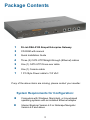
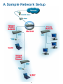
D-Link Airspot
DSA-5100
Enterprise Gateway
Manual
July 2004
Rev. B
Building Networks for People
Contents
Package Contents ................................................................................3
Introduction...........................................................................................4
Front Panel ...........................................................................................5
Rear Panel ...........................................................................................5
Features ...............................................................................................6
Sample Network Setup .........................................................................8
Installation ............................................................................................9
Setting Up the DSA-3100 .....................................................................9
TCP/IP Network Setting .....................................................................10
Internet Access Configuration ............................................................ 11
Using the Configuration Utility ............................................................13
Networking Basics ..............................................................................62
Technical Specifications .....................................................................77
Technical Support ...............................................................................79
Warranty .............................................................................................80
Appendix: Windows TCP/IP Setup .....................................................83
2
Package Contents
1
D-Link DSA-5100 Airspot Enterprise Gateway
2
CD-ROM with manual
3
Quick Installation Guide
4
Three (3) CAT5 UTP/Straight-through (Ethernet) cables
5
One (1) CAT5 UTP/Cross-over cable
6
One (1) Console cable
7
1 PC-Style Power cable to 110 VAC
If any of the above items are missing, please contact your reseller.
System Requirements for Configuration:
Computers with Windows, Macintosh, or Linux-based
operating systems with an installed Ethernet adapter
Internet Explorer Version 6.0 or Netscape Navigator
Version 6.0 and above
3
Introduction
The D-Link DSA-5100 Airspot Enterprise Gateway is an advanced network access
control system supporting Ethernet, Fast Ethernet or an IEEE 802.11 wireless LAN
(WLAN) separately and simultaneously.
The DSA-5100 can be configured with a standard HTML browser (i.e., Internet Explorer,
or Netscape Navigator) operating on Windows 98SE/Me/2000/XP, Macintosh OS 9,
Macintosh OS X (v10.1.5 or later), Linux, or Pocket PC 2000/2002. The DSA-5100
allows the operator to offer wired or wireless networking services and access to the
Internet when used with a switch or wireless access point respectively. The device
features many management settings allowing for private and public access to the
Internet and the necessary privilege mechanisms to permit this usage.
4
Front Panel
Power LED A solid light indicates that the
system is ready.
Link LEDs - a solid light
indicates a connection
to the network.
Act LEDs - a
blinking light
indicates a activity
on the network.
Status LED Upon starting up the
DSA-5100, this LED
will blink momentarily.
A solid light indicates
that the system is
ready.
Aux Port Reserved for future usage.
Private LAN PortCan be connected to the
Intranet environment by
switch or Ethernet without
authentication in order to
log on to the Internet.
Console Port Connect to
return the unit to
factory default
settings, or to
reconfigure
system settings.
WAN 1 PortConnect to an
ATU-Router of
ADSL, a cable
modem or a
switch for
Internet or
Intranet
access.
WAN 2 PortConnect to a switch
or cable modem for
Internet or Intranet
access.
Public LAN PortCan be connected to the
open network environment
managed by the system or
WLAN, and requires
authentication before logging
on the Internet.
Rear Panel
Connector for Power Cord.
Power SwitchON/OFF switch.
5
Features
Supports IEEE 802.1x
Supports IEEE 802.1q VLAN
Supports IEEE 802.3 ad
WAN interface supports static IP, DHCP client, and PPPoE client
WAN2 interface supports static IP
Supports NAT mode, router mode and bridge mode
Built-in DHCP server
Built-in NTP client
Supports redirect of network data
Supports IPSec(ESP), PPTP and H.323 pass through (under NAT)
Customizable static routing table
Supports virtual server
Supports DMZ server
Supports machine operation status monitoring and reporting system
Supports roaming across networks
Provides several DoS protection mechanisms
Customizable packet filter rules
Customizable walled garden (free surfing area)
The DSA-5100 supports at least 400 on-line users concurrently
Supports POP3, RADIUS, and LDAP authentication mechanisms
Supports two or more authentication mechanisms simultaneously
Can set the time for the user to logon to the system
Can set the user’s idle time
Can specify the connection to MAC address without authentication
Can specify the connection to IP address without authentication
6
Features (continued)
Permits or refuses all connections when the WAN interface fails
Supports Web-based logon
Provides several friendly logout methods
Supports RADIUS account roaming
Provides online status monitoring and history traffic
Supports SSL encrypted web administration interface and user logon interface
Customizable user login & logout web interface
Customizable redirect after users are successfully authenticated during login & logout
Supports Console management interface
Supports SSH remote administration interface
Supports Web-based administration interface
Supports SNMP v2
Supports user’s bandwidth restriction
Supports remote firmware upgrade
Supports built-in user database and RADIUS accounting
7
A Sample Network Setup
8
Installation Requirements
1.
Standard 10/100Base-T, including four network cables with RJ-45
connectors.
2.
All PCs need to install the TCP/IP network protocol.
Setting Up the DSA-5100
1.
Make sure the power of the DSA-5100 is turned off.
2.
Connecting the WAN1 and WAN2 ports.
Use one of the supplied straight-through cables to connect the DSA-5100 to the network
not managed by the DSA-5100 system (such as and ATU router for ADSL, the Ethernet
port of a cable modem, or a switch or hub on a LAN).
3.
Connecting the Public LAN port.
The Public LAN port is used to provide authentication based Internet access for Ethernet
(with switch) or WLAN (with AP) clients. Use one of the supplied straight-through
Ethernet cables if connecting to a hub or switch. Use the supplied crossover cable if
connecting directly to an AP or PC.
Warning: The Public LAN port cannot connect to a Layer 3 device.
4.
Connecting the Private LAN port.
The Private LAN port is used to provide Internet access without authentication for
your existing Private Network. Use one of the supplied straight-through Ethernet cables
if connecting to a hub or switch. Use the supplied crossover cable if connecting directly
to an AP or PC.
5.
Turn on the power.
Plug the bundled power cord connector into the socket and then turn on the power.
6.
Check the LED indicating light.
After the power is ON, the power LED should be lit. The WAN1, WAN2, Public LAN,
and Private LAN LEDs will light up with a valid Ethernet connection.
9
Setting Up the DSA-5100 (continued)
TCP/IP Network Setup
For Windows 98SE/ME/2000/XP, you need to keep the default TCP/IP settings
(“obtain IP and DNS address automatically”) to communicate with the DSA-5100.
The DSA-5100 leases DHCP addresses from the Public and Private LAN ports
for ease of configuration.
For Non-Server Windows operating systems, the default setting for TCP/IP is
“DHCP client,” which will obtain an IP address automatically.
If you wish to use a static IP on the public or private LAN section, or you wish to
check the TCP/IP setup, please refer to the Appendix – Windows TCP / IP Setup.
10
Internet Access Configuration
To configure your PCs to use the DSA-5100 for Internet access, follow this
procedure.
For Windows 98SE/2000
Please select Start
Menu - Control Panel Internet Options.
Select the Connection
tab, and click the Setup
button.
11
Internet Access Configuration (continued)
Select “I want to set
up my Internet
connection manually,
or I want to connect
through a local Area
network (LAN)” and
click Next.
Select “I connect through a local area network (LAN)” and click Next.
Ensure all of the boxes on the local area network Internet configuration
screen are unchecked.
Check No, when prompted “Do you want to set up an Internet mail
account now?” Click Next.
Click Finish to close the Internet Connection Wizard. The Internet
Connection Setup is now complete.
For Windows XP
Select Start Menu - Control Panel - Network and Internet Connection.
Select the Connection tab, and click the Setup button.
Click Next on the New Connection Wizard screen.
Select Connect to the Internet and click Next.
Select Set up my connection manually and click Next.
Check Connect using a broadband connection that is always on and click
Next.
Click Finish to close the New Connection Wizard. Internet Connection Setup
is now complete.
12
Using the Configuration Utility
To configure the DSA-5100, connect a computer to the Private LAN port of the
DSA-5100 with the supplied crossover Ethernet cable.
First, disable the Access the Internet using a proxy server function. To
disable this function, go to Control Panel > Internet Options > Connections
> LAN Settings and uncheck the enable box.
Start your Microsoft Internet Explorer Web browser program.
Type the IP address of the
DSA-5100 (the default IP
address is 192.168.0.40,
preceded by https://) in the
address field and press Enter.
Make sure that the IP addresses
of the DSA-5100 and your
computer are in the same
network.
Log-in Screen
You can log in as admin
or as manager.
admin The administrator of
the DSA-5100.
User Name: admin
Password: admin
manager Access to the manager
user account only.
User Name: manager
Password: manager
After you log in, click Enter.
13
Using the Configuration Utility (continued)
System Configuration > Configuration Wizard
The System Configuration>Configuration Wizard screen will appear if you logged
in as admin. For more information on the Setup Wizard, please see the Installation
Guide, included with your purchase. You can access the configuration features
from this window.
User Authentication > Authentication policies
The User Authentication>Authentication policies screen will appear if you logged
in as a manager. For more information on the Setup Wizard, please see the Installation
Guide. You can access the configuration features from this window.
14
Using the Configuration Utility (continued)
System Configuration > System Information
System
Name:
DSA-5100 is the default system name. You may wish to rename it to
indicate your company, department, or the service you would like to
provide.
Administrator You can edit the System Administrator’s information here (e.g., name,
Info:
phone number, and e-mail).
Succeed
Page:
Enter a URL which all users will be re-directed to after a successful
login. This is typically defined as the home page of the host company,
e.g: http://www.dlink.com. No matter which URL a user originally
attempts to connect to, he/she will be directed to the URL defined
here first.
Remote
Manage IP:
You can allow SSH or HTTPS connections from the WAN for
management purposes. Access is limited to a specific IP address or
network (e.g., 192.168.2.1 might be used for a specifici IP address.
10.2.3.0/24 for a specific IP Network. 24 indicates the number of bits
for the subnet mask).
Access
Specify an IP address to be used by the billing system to connect to
History IP : the DSA-5100 to get billing history information.
15
Using the Configuration Utility (continued)
System Configuration > System Information (continued)
SNMP:
The DSA-5100 supports SNMP v2 read only data access. The
Administrator can specify the IP address and the SNMP community
name to determine the target of the management information base
(MIB) exported from the DSA-5100.
User Logon Allows the admin to choose either https (encrypted username/
password), or http (non-encrypted username/password) as the login
SSL:
page.
Time:
Enable NTP: The DSA-5100 supports NTP communication protocol
for correct network time. Please specify the IP address or DNS
name of an SNTP server on the system configuration interface.
Time Zone: Set up the time zone for the DSA-5100. The
default is GMT+08:00. (Taipei)
Set Device Date and Time: Manually specify system time.
16
Using the Configuration Utility (continued)
System Configuration > WAN1 Configuration > Static IP Mode
Static IP
Address: IP address: Enter the IP address provided to you by your ISP (Required).
Subnet
mask:
Enter the subnet mask provided to you by your ISP. All
devices on the network must share the same subnet
mask (Required).
Default
Gateway:
Enter the gateway IP address provided to you by your
ISP (Required).
Primary
DNS
Server:
Enter the IP address of the primary DNS server
(Required).
Secondary
DNS
Server:
Enter the IP address of the secondary DNS server
(Optional).
Bridge
Mode:
This device can be configured in Bridge mode. All
interfaces bind to the same IP. Only one set of IP
addresses can be used for management. The advantage
is that there is no need to readjust any network
infrastructure, just plug and use. When you click Enable,
the VLAN function of the Public LAN is disabled.
Note: WAN1 must have a static IP address in order to utilize the 802.3ad WAN link
aggregation feature. If you cancel the static IP address, then the option of choice for
802.3ad is also canceled. (Please see the WAN2 configuration that follows for
information on configuring 802.3ad.)
17
Using the Configuration Utility (continued)
System Configuration > WAN1 > Dynamic IP Address
Select this option if there is a DHCP server on the network or to obtain an IP
address automatically from your ISP.
Renew: Click Renew to renew the IP configuration.
System Configuration > WAN1 > PPPoE
Most DSL users will select this option.
User Name & Password:
Enter the user name and password that is assigned by your ISP.
Maximum Idle Time & Dial on demand:
These fields are optional.
18
Using the Configuration Utility (continued)
System Configuration > WAN2 > Static IP Address
Static IP
Address:
IP address: Enter the IP address provided to you by your ISP.
Subnet
mask:
Enter the subnet mask provided to you by your ISP. All
devices on the network must share the same netmask.
Default
Gateway:
Enter the IP address of the gateway provided to you
by your ISP.
Dynamic IP Choose this option if there is a DHCP server on the unmanaged
network.
Address:
802.3ad:
Set WAN2 to 802.3ad mode only if WAN1 is configured for a static IP.
When 802.3ad is enabled, the sum of the bandwidths of WAN1 and
WAN2 is used for the total bandwidth (provided that WAN1 and WAN2
are connected to the same switch(es) that also supports 802.3ad.
19
Using the Configuration Utility (continued)
System Configuration > Public LAN > Global Public LAN Configuration
You can set the system to start or stop IP PNP or Mobile IP on the Public LAN and
Private LAN simultaneously.
1. IP PNP: At the user end, you can use any IP address (with gateway and
DNS address) to connect to the Internet; no matter what the IP address at
the user end is, you can access the network resources properly and
authenticate through the DSA-5100.
Note: This function can only be activated under NAT.
2. Mobile IP: If you construct a network environment using several
DSA-5100s, a user can use the same group of IP configurations. When you
roam at different locations, or download data, the connection will not be
disconnected.
System Configuration > Public LAN > Public LAN Configuration
If you want to configure multiple Authentication networks on the Public LAN, please
select the Enable VLAN option on the public LAN interface.
After the Enable VLAN option is selected, the following screen will appear. Choose
the desired Item and click Edit to enter the VLAN interface configuration screen.
20
Using the Configuration Utility (continued)
System Configuration > Public LAN > Public LAN Configuration (continued)
The system will confirm if you want to Enable VLAN; please click Enable to continue.
After you click Enable, the following screen will appear. See the following description
for details.
Enable/Disable: Enable or Disable the functions of VLAN.
User Authentication: Control the User Authentication method or policy according
to individual VLAN.(default is Disabled).
21
Using the Configuration Utility (continued)
System Configuration > Public LAN > Public LAN Configuration (continued)
VLAN Tag: Please enter any numbers from 0~4000 as a Tag for each VLAN. (These
VLAN IDs must match the managed switch.)
Specific Route Profile: Select your desired Specific Route Profile rules from the
pull-down menu, or choose None. (It will appear after disabling the User Authentication
option.)
Mode: NAT Mode: All IP addresses externally connected through the VLAN Port
(these IP addresses must belong to the same network as the
VLAN Port) will be converted into the IP address of the WAN1
Port by the DSA-5100 and connected to the outside.
Router Mode: All IP addresses externally connected through the VLAN Port
use their own IP address for external connections. In this case,
the DSA-5100 functions as a router.
IP Address: Enter the desired IP address for the VLAN Interface.
Subnet Mask: Enter the desired Subnet Mask for the VLAN Interface.
Public LAN > VLAN > DHCP Configuration
Disable DHCP Server: Choose this option if you do not wish to use the built-in
DHCP Server feature in the DSA-5100.
Enable DHCP Server: Selecting this option activates the device’s built-in DHCP
server. Configure the DHCP server with the following properties:
22
Using the Configuration Utility (continued)
Public LAN > VLAN > DHCP Configuration (continued)
Enable DHCP Server (continued):
DHCP Scope
Start IP
Address:
Enter the starting IP address of the pool, from which the
DHCP server will assign to the DHCP-enabled devices
(clients) on the network.
End IP
Address:
Enter the last IP address in the sequence of addresses from
which the DHCP server will assign addresses.
Primary
DNS Server:
Enter the IP address of the preferred DNS server.
Secondary
DNS Server:
Enter the IP address of the alternate DNS server.
Domain Name:
Enter the domain name.
WINS
IP Address:
Enter the WINS server’s IP address (if present).
Lease Time:
Select the length of time during which the DHCP assigned
address will be in effect.
Note: The DHCP client will attempt to re-obtain its IP lease after half of the lease
time has already expired. Using a low number will increase traffic on the network.
23
Using the Configuration Utility (continued)
Public LAN > VLAN > DHCP Configuration (continued)
Enable DHCP Server (continued):
Reserved IP
Address List:
Enable
DHCP Relay:
If you want to use the Reserved IP Address List function, please
click the hyperlink of the Reserved IP Address List on the
management interface. Then, the setup of the Reserved IP
Address List as shown in the following figure will appear.
Please enter the related Reserved IP Address, MAC, and
description (optional) on the management interface. After the
information is entered, click Apply to complete the setup.
In order to enable the DHCP Relay Mode, you must specify a
DHCP server IP address.
24
Using the Configuration Utility (continued)
System Configuration > Private LAN Configuration
For an explanation of each field on this screen, please see the previous screen:
System Configuration > Public LAN Configuration.
25
Using the Configuration Utility (continued)
User Authentication
User Authentication allows the DSA-5100 owner/operator to control who has or does
not have access to the Internet. The DSA-5100 can support five different authentication
types simultaneously.
User Authentication > Authentication Policies
The DSA-5100 provides a simple interface to allow the administrator to easily
complete the complicated management setup. The system provides a total of 5
authentication setups. The administrator can adopt different authentication
methods corresponding to each management setup. Each management setup can
use at most 20 management rules to go with the group configuration, so that the
management of general users can be both diversified and flexible.
The administrator can select the desired management setup through the pull-down
menu.
Item:
Provides 5 sets of authentication policies.
Policy Name: The name of the policy can be modified here.
Status:
Default:
Enable or Disable the policy.
Group:
Edit:
Currently assigned group.
Select Yes for the default setup.
Click Edit to edit the policy.
26
Using the Configuration Utility (continued)
Edit Authentication Policies
Authentication
Policy:
Displays the system’s preferred authentication method.
Policy ID:
Select the policy you wish to edit here.
Set as Default: Make this selection to set the policy you have chosen to be
the default Authentication policy.
Policy Name: Enter the postfix policy name.
Policy Status: Select Enabled or Disabled to activate or deactivate the
selected policy.
Black
List Profile:
Enter the profile name to be blacklisted.
Authentication Server
The authentication server provides 6 authentication modes:
Local, POP3, RADIUS,LDAP,NT Domain, and External Web Server.
Assign
to Group:
Assign a group to the control group from the pulldown menu.
Exception
Configuration: When you enable this feature you can exclude accounts
from restrictions using the Edit feature. (This feature is
displayed on the following page.)
27
Using the Configuration Utility (continued)
Authentication Server> Exception Configuration
Attribute:
After the authentication, the DSA-5100 will obtain the user’s
attributes related to the authenticated server. The administrator
can use certain attributes as the management rule for the setup.
Logic:
Logic options include equal to, not equal to, larger than,
smaller than, and include.
Value:
Please fill in the desired value after the attribute and logic
fields have been completed.
Group:
Specifies the priority.
Default Group: When a user does not match the management rule logon, this
priority rule will be applied.
Warning: The policy name cannot include: GRIC, MAC, IP
28
Using the Configuration Utility (continued)
Authentication Methods>Local>Local Users List
The user’s account information is stored in the DSA-5100. If you need to manage the
user’s account, please click the hyperlink Local Users List on the Authentication Server
interface to enter into the Account Management Interface, shown below.
User List:
It provides a complete list of existing user accounts, including information
such as Username, Password, MAC, Group, and Remark. The
administrator can delete or search for a single user from this
management interface.
Delete All:
Click here to delete all user accounts.
Edit:
To edit the content of an individual user account, click the hyperlink of
the selected user account to enter the edit mode.
Refresh:
Click here to show the most updated user account information.
Authentication Methods > Local > Local Users List > Add User
Add User:
Create new accounts,
including Username
(mandatory), Password
(mandatory), and MAC
(optional), and assign to
a user group.
Edit Account:
Make changes to the
account by clicking on
the Username. When
the screen on the next
page appears, edit the account information.
29
Using the Configuration Utility (continued)
Authentication Methods > Local > Local Users List > Add User>
Edit Account
Edit Account:
Edit the account here.
Local Users List > Add User> Upload User Account
Upload User
Account:
Click the Browse button
to select the text file for
the user account. Click
Submit to complete the
upload. The format of the uploaded file should be a text file. Each line represents a
User Account. The format is Username, Password, MAC, Remark. Each parameter is
separated by a comma, and no space is allowed between MAC,Remark, but a comma
is still needed.
Local Users List > Add User> Download User Account
Download
User
Account:
Click the Download
User Accounts to
view a list of all the
user accounts. To save
a new file, click
download.
Click download to
load accounts into
your computer.
30
Using the Configuration Utility (continued)
Authentication Methods > POP3
If a POP3 Server is used for
user authentication, select
POP3 in the interface
shown here. The setup for
the primary server or the
secondary server (optional)
is available. Enter the IP
address or domain name of
the Primary POP3 Server
and its Primary POP3
Server port. Click Apply to
enable the setting.
Enable SSL Connection: If you select this option, the authentication will be done by
POP3 Protocol with SSL Username/Password encryption.
Authentication Methods > RADIUS
The DSA-5100 supports
RADIUS Client to work
with an existing RADIUS
server.(Primary is
required; Secondary is
optional.)
802.1X Authentication:
Select to enable 802.1X
(in conjunction with a
switch or AP that supports
802.1X).Click Edit to enter
into the edit interface of
802.1X.
Trans Full Name:
Enable: ID and postfix will
transfer to the RADIUS
server for authentication.
(e.g., user@postfix1).
Disable: Only the ID will transfer to the RADIUS server for authentication. (e.g., user).
Server IP: Key in the location of the RADIUS server by its IP Address or Domain
Name.
Authentication Port: The authentication port for the RADIUS server.
Accounting Port: The port reading the accounting information.
Secret Key: This is used for encryption and decryption. (Must be configured on both
RADIUS Server and DSA-5100.)
Accounting Service: Select to enable the accounting service (optional).
31
Using the Configuration Utility (continued)
Authentication Methods > LDAP
You may configure a
primary and a
secondary server for
LDAP authentication.
If you select the
LDAP authentication
method, type in the IP
Address (Domain
Name), Port number,
the Base DN Data of
LDAP Server, and the
Account Attribute.
Click Apply to save
the changes.
Authentication Methods > NT Domain
Server IP Address: Enter the IP address of the Domain Controller Server.
Transparent Login: Select Enable or Disable.
Assign to Group: Select the group from the pulldown menu.
Exception Configuration: Select Enable or Disable.
Caution: The NT Domain feature supports only a Windows 2000
controller. To use NT Domain Authentication please ensure the
following conditions:
1. The WAN1 port preferred DNS server IP address must be the
same as the Domain Controller Server IP address.
2. The Free Surfing List must also contain the Domain Controller
Server IP address.
3. The Policy name must be your complete Domain name.
32
Using the Configuration Utility (continued)
External Web Server
The DSA-5100 supports an external web server function (including database)
which enables a user to put the login page on an external web server, and change
the login page anytime.
Protocol: Choose from http or https (http protocol is selected here).
Server IP: External Web server IP.
Server Port: External Web server Port number.
Login Page: Login page URL.
User Authentication>Group Configuration
The administrator can configure 5 group profiles and a guest profile here. Click Edit
next to the group that you want to configure and the screen on the next page will
appear.
33
Using the Configuration Utility (continued)
User Authentication>Edit Group Configuration
Group Name: Assign a group name; Guest is selected here.
Firewall Profile: Select the firewall profile for this group.
Specific Route Profile: Select the route profile for this group.
Schedule Profile: Select a schedule for this profile.
Bandwidth: Select the bandwidth limit that goes with this group.
User Authentication>Black List Configuration
The administrator can manage a blacklist of up to 40 users. When a blacklisted user
attempts to logon, he will be denied access.
Select Black List: Select the blacklist from the pulldown menu.
Add User to List: Click on this link and the interactive screen on the next page will appear.
34
Using the Configuration Utility (continued)
User Authentication>Black List Configuration
Username: Enter the username to be blacklisted here.
Remark: Add a comment (optional).
Apply: Click Apply to add the user to the blacklist.
Previous: Click Previous to return to the Black List Configuration.
35
Using the Configuration Utility (continued)
User Authentication>Black List Configuration>Delete a User
Delete: To delete a user, check the box in the Delete column, and then click the
Delete button.
No notification will appear to confirm the deletion.
User Authentication>Guest User Configuration
Enable:
Select Enable to activate the Guest Account feature for visitors.
Guest User
List:
Click to view the interactive screen (shown on the next page). Up
to 10 guest accounts can be defined.
Session Length: You have the option to limit the guest’s session time from 1-12
hours. By default, there is no limit to a guest’s session.
Idle Timer:
When enabled, on-line users who become inactive on the network
after a specified period of time will be logged out automatically.
The period can range from 1-1440 minutes. Ten minutes is the
default value.
36
Using the Configuration Utility (continued)
User Authentication>Guest User List
Password:
Enter a password to
activate a guest
account. Up to ten
guest accounts can be
defined.
User Authentication>Roaming Configuration
The system provides a GRIC Service for roaming. Set up the parameters in this page
to let the user of the GRIC Service use the DSA-5100. Click Apply.
The GRIC user will be able to use the webpage GRIC.shtml, and is provided with
username, password, IP, and MAC, so that the DSA-5100 will provide the authentication
and authorization functions.
Caution: The login location is the same as the location of the account’s
origin. For example if the account was opened in Los Angeles, then the
login location is Los Angeles.
37
Using the Configuration Utility (continued)
User Authentication>GRIC example
Here is a GRIC example:
DSA-5100 Public LAN port IP address: 192.168.1.254
Username: xyz, and his IP address: 192.168.1.100
Password: xyz
MAC address: 01:23:45:67:89:ab
The gric.shtml example should look like this:
https://192.168.1.254/loginpages/
gric.shtml?uname=xyz&uip=192.168.1.100&upwd=xyz&umac=01:23:45:67:89:ab
The user can also use the browser to key in the GRIC\username or
username@GRIC in the ID field, and to enter the user’s password from the login
Web page to be used for authentication.
User Authentication>User Control
Logout Timer: If a user
is idle and has not used
the network for the
configured time, the
system will automatically
log out the user. The
logout time can be set
from 1-1440 minutes. The
default logout time is 10
minutes.
Multiple Login:
After you have selected this function, the user with the same ID can logon from several
computers.
Friendly Login:
After you select this function, the logon page will automatically obtain the username
and password from the previous authentication logon. The user no longer needs to
click the button to login. If this option is not selected, the user has to click Login and
enter the username and password (which will be saved for 12 hours).
38
Using the Configuration Utility (continued)
User Authentication>User Control (continued)
Friendly Logout:
When a user logs on, a small window will appear, showing the user information and
providing him or her with a button for logout. If this option is enabled, it will close the
window and logout the user. If you do not select this option, closing the window will not
log out the user. To logout, browse to https://1.1.1.1/logout.shtml
WAN Fail:
The DSA-5100 can detect if the WAN connection fails by using an ICMP echo
mechanism to ping the default gateway and the DNS server periodically.
Pass: Allows free access without control.
Block: Displays the error message and blocks all access. (More secure.)
POP3 Message:
Before a user logs on to the
system with the username and
password, the user may receive
a welcome e-mail. If you want to
set the content of the e-mail,
please fill in the text in the table
shown here.
MAC Address Control:
When MAC Address Control is
enabled, only 40 users can
connect to the Authentication Port
and login to the DSA-5100 if they
have previously registered their
MAC Address in MAC Address
Control. Please refer to the
configuration screen shown here.
The format of the MAC address can be
XX:XX:XX:XX:XX:XX or XX-XX-XX-XX-XX-XX.
39
Using the Configuration Utility (continued)
User Authentication>Upload File
Private Key/
Customer
Certification:
The DSA-5100
allows the user to
upload customer
certification. (The
key must be in key
format and the
certificate must be
in certificate format.)
File Name:
Enter the filename
of the logon Web
page or click
Browse to browse
for the file on your
local PC.
Login Page:
Use default page:
Click to recover the factory default setting of the logon interface.
Submit:
Click to begin uploading the page.
Preview:
After the upload is completed, click Preview (at the bottom of the page) to preview the
user-defined logon interface.
HTML codes:
The user-defined login interface must include the following HTML code to provide a
channel for the user to key in the username and password:
<form action=”userlogin.shtml” method=”post” name=”Enter”>
<input type=”text” name=”myusername”>
<input type=”password” name=”mypassword”>
<input type=”submit” name=”submit” value=”Enter”>
<input type=”reset” name=”clear” value=”Clear”>
</form>
40
Using the Configuration Utility (continued)
User Authentication>Upload Graphic File
If the user-defined logon interface includes a graphic file, the HTML code of the graphic
file path must be uploaded. Key in the path and file name of the graphic file or Browse
to select the file. The maximum size of the graphic file is 512K.
An example of an HTML path for a graphic file:
<img src=”images/xx.jpg”>
After the graphic file is uploaded, the uploaded files will
be listed in the window
shown below. You can select
or delete any graphic file that
is displayed here.
Click Preview to view the
graphic file.
User Authentication>Upload Logout Page
The system will provide you
with the user-defined logout
interface, which is similar to
the user logon interface.
The user-defined user logout
interface must include the
HTML codes, shown on the
following page, to provide
users a channel to enter the
username and password.
41
Using the Configuration Utility (continued)
User Authentication>Upload Logout Page>HTML codes
Use the following HTML codes for the User Logout Interface:
<form action=”userlogout.shtml” method=”post” name=”Enter”>
<input type=”text” name=”myusername”>
<input type=”password” name=”mypassword”>
<input type=”submit” name=”submit” value=”Logout”>
<input type=”reset” name=”clear” value=”Clear”>
</form>
Upload Error Page
To provide a custom
user login error page,
please specify the file
name to upload to the
DSA-5100. If you want
to get back to the Error
page, click Use Default
Page. If you want to
display the Login Error
Page, click Preview.
Upload Login Successful Page
To provide a custom
user login succeed
page, please specify the
file name to upload to
the DSA-5100. If you
want to get back to the
Succeed page, click
Use Default Page. If you
want to display the Login Succeed Page, click Preview.
Upload Logout Successful Page
To provide a custom
user Success page,
please specify the file
name to upload to the
DSA-5100. If you want
to get back to the default
user Success page,
click Use Default Page.
If you want to display the Logout Succeed Page, click Preview.
42
Using the Configuration Utility (continued)
The DSA-5100 provides three kinds of Profile configurations, including Firewall Profile,
Specific Route Profile, and Login Schedule Profile.
Group Profile > Firewall Profile
Global is the default
setting. Use the
Global setting to
apply parameters to
all users. There are 5
individual profiles
available also.
Profile Name:
To give a name to
the Firewall Profile.
Filter Rule Item:
Click the number to
edit the filter rule.
The window below will appear.
Group Profile > Firewall Profile>Edit Filter Rule
Rule Name:
The name of the IP
filter rule.
Enable this Rule:
Check to enable this
rule.
Action:
Specifies the action
to be taken when
packets match the
rule.
Pass: Packets matching the rule will be passed.
Block: Packets matching the rule will be dropped.
Protocol:
Provides three kinds of protocols: TCP, UDP, and ICMP. Select All to apply all three
protocols.
43
Using the Configuration Utility (continued)
Group Profile > Firewall Profile>Edit Filter Rule (continued)
Source MAC:
MAC address of the Network component sending the request.
Source (Destination) Interface:
Source (Destination) Interface includes 4 interfaces: WAN1, WAN2, Public LAN, and
Private LAN. Select ALL to apply to all four interfaces.
Source (Destination) IP Address:
IP address of the Network component sending (receiving) the request.
Source (Destination) Subnet Mask:
Subnet Mask of the Network component sending (receiving) the request.
Source (Destination) Operator:
Provides the comparison rules: =(Equal), != (Not Equal), >(Larger Than), and <(Less
Than).
Source (Destination) Start Port:
Start Port of the Network component sending (receiving) the request.
Source (Destination) End Port:
End Port of the Network component sending (receiving) the request.
44
Using the Configuration Utility (continued)
Group Profile > Specific Route Profiles
If you want networks to have
access to each other, you
should add a specific route in
the DSA-5100.
Profile Name:
Name the specific route profile.
Destination IP Address:
Specifies the target network or
host IP
Subnet Netmask:
Specifies the target subnet
mask.
Gateway IP Address:
Specifies the IP address of the next hop router.
Caution: To allow two machines to access data from each other,
add a static route to the next connected router in order to send all
packets back to the DSA-5100.
After the static route is changed, it is necessary to restart the
DSA-5100 to enable the static route.
45
Using the Configuration Utility (continued)
Group Profile > Login Schedule Profiles
The user’s login schedule can be
set. After durations are defined,
please click Apply to save the
settings in the DSA-5100.
Network Configuration > Network Address Translate
DMZ
If you have several IP addresses,
you can assign them to the WAN
port of the system. You can define
at most 40 Public IPs for the
corresponding combination at the
Ethernet end (Virtual IP Address)
and WAN end (Public IP Address).
The WAN port of the system will
automatically set the public address
defined here. These settings will be
effective immediately after you click
the Apply button.
Virtual Server
The function of this item permits you
to define at most 40 virtual servers,
so that computers may access LAN
resources from the WAN interface.
The Virtual Server function also
allows one to specify the type of
traffic allowed, TCP, UDP or both.
These settings will be effective
immediately after you click Apply.
46
Using the Configuration Utility (continued)
Network Configuration > Network Address Translate (continued)
Port and IP Redirect
When any user attempts
to connect to a
destination defined in
this interface, the
connection packet will
be converted to the
corresponding
destination. You can
define up to 40 groups
for redirection on this
interface. These settings
will
be
effective
immediately after you
click Apply.
Network Configuration > Privilege List
IP Pass Through Configuration
To permit a specific
device at the user end to
have network access
without going through
authentication, you only
need to key in the IP
address of the user on
this interface. This
system permits at most
100 IP addresses to
have network access
without going through
authentication. These
settings will be effective
immediately after you
click Apply.
Warning: Permitting specific IP addresses to have network access
rights without going through authentication may cause security
problems.
47
Using the Configuration Utility (continued)
Network Configuration > MAC Pass Through Configuration
You can also bypass
authentication based on
the MAC address at the
user end. Please enter
the MAC address of the
user on this interface.
This system permits at
most 100 MAC
addresses to have
network access rights
without going through
authentication. The
format of the MAC
address is
XX:XX:XX:XX:XX:XX.
These settings will be effective immediately after you click Apply.
Warning: Permitting specific MAC addresses to have access rights
without going through authentication may cause security problems.
Network Configuration > Monitor IP List
The system will send out
a packet regularly to
monitor and control the
status of the devices on
the list. If the monitored
IP address does not
respond, the system will
send out an E-mail to the
admin once every 30
minutes, such as 1:00,
1:30, 2:00, 2:30, and
3:00 until the problem is
fixed. A maximum of 20
IP addresses can be
monitored here. Click
Monitor to view all
monitored IP addresses.
48
Using the Configuration Utility (continued)
Network Configuration > Monitor IP List (continued)
Notify Configuration
Admin E-mail:
The DSA-5100 will save the history to the internal DRAM. If you want to automatically
send the history to your E-mail address, please enter your E-mail address in the
Admin E-mail column. You will also need to configure this for the Monitor IP function
to work.
Interval:
The Interval column shows the interval for sending the history E-mail. If you choose
one day, then the history mail will be sent to you once a day.
Network Configuration > Free Surfing Area
The Free Surfing Area permits users to logon to certain websites or Domains before
passing through authentication. You can enter up to 20 IP addresses (or Domain
Names) into the Free Surfing Area. This function allows you to provide potential users
a free network experience, while introducing them to your site. All unauthenticated
requests to servers not on the list will be dropped.
49
Using the Configuration Utility (continued)
Network Configuration > Proxy Server Properties
Internal Proxy Server:
Enable this function to configure the DSA-5100 as a proxy server.
External Proxy Server:
By default, only port 80 is allowed. It will appear on the login Web page. If you have
built a Proxy Server in your network environment, and the user’s browser is set to
Proxy, you must set your External Proxy Server IP address and Proxy Port in this
section fo the configuration in order to operate in the Proxy network environment.
50
Using the Configuration Utility (continued)
Utilities > Change Password
DSA-5100 provides 2 built-in user accounts: admin and manager.
admin: This user is the administrator in the DSA-5100.
manager: This user has the right to manage a user account, the admin functions are
denied.
The admin and manager can change their passwords; specify the current password
first. The new password must be entered twice.
Note: If you lost or forgot the Administrator’s Password, you can
reset it through the text mode management interface of the serial
port.
51
Using the Configuration Utility (continued)
Utilities > Backup/Restore Strategy
This utility provides the backup function, and the ability to restore backup settings.
This function can also restore the factory default settings to the system.
Create Backup Image:
Create: Generate the backup (image) file.
Save as: Download the backup (image) file.
Restore Settings From File:
Browse: Browse for the backup file.
Restore: Click to load the selected backup file for
the setup status.
(Caution: The image file must be generated by the
the system).
Reset to Factory Default:
Restore to the factory default setting of the system.
52
Using the Configuration Utility (continued)
Utilities > Firmware Upgrade
You may obtain firmware upgrades from D-Link’s support website:
http://support.dlink.com
Warning: A Firmware upgrade may cause data loss on setup. Please
refer to the version description to see if there is any limitation before
upgrading your firmware.
Click Browse to browse the files. After you have found the firmware, click Submit and
the browser will upload the file to the system. The system will start upgrading the
firmware.
You must restart the system before the firmware upgrade is effective. If you have
modified any setting, remember to save the setting before restarting the system.
Warning: Please restart the system through the management
interface. Do not turn off the system directly and then turn on the
power again. (Doing so may damage the unit.)
Utilities > Restart
This function allows you to safely restart the system. It takes about one minute.
OFF:
If you need to turn OFF the power, we recommend that you first RESTART
the system, and then turn OFF the power, AFTER you hear a beep.
Warning: All online users connected to the system will be
disconnected when the system is restarted.
53
Using the Configuration Utility (continued)
Status> System Status
You can use this function to get the overview of the system status. Please refer to the
following example.
54
Using the Configuration Utility (continued)
Status> System Status (continued)
Item
Description
Current Firmware Version
The firmware version currently used by the DSA-5100.
System Name
System name - the default is DSA-5100.
Admin Info
Administrator’s information will be shown on the
logon screen when a user has a connection problem.
Succeed Page
The starting URL after a user logs on successfully.
Syslog to
The IP address and port number of the external Syslog server.
Proxy Server
Proxy Server is not set.
WAN Fail
When the connection at WAN is abnormal (WAN Fail), all
online users can log on to the network.
Manage Remote Manage IP
It permits a specific IP address to set up the DSA-5100
from the WAN1 port.
SNMP
Do not enable SNMP management function.
Retain Days
The system will retain the user information up to a maxi mum
of 3 days.
E-mail To
Send the history to this email address.
Time Server Name
The DSA-5100 uses an external Time Server to check
time.
Date Time
The system time is Greenwich time.
Logout Timer
Multiple Login
Guest Account
It is the logout time for idling. The online user will be
forced to logout after being idled for 10 minutes.
It does not allow multiple logins for a user.
Enable the Guest Account.
Primary DNS server
Primary DNS Server IP Address.
History
Time
User
DNS
Secondary DNS server Secondary DNS Server IP Address.
Friendly Login
Logout
User must click “Login” to execute the login procedure. The
system will not automatically get the username and password
from the previous login for the direct authentication login.
If a user logs in, a small window will show the user’s
information and provide a logout button for the logout.
Selecting Disable ensures that closing the small window
will not cause a logout to the user.
55
Using the Configuration Utility (continued)
Status> Interface Status
56
Using the Configuration Utility (continued)
Status> Interface Status (continued)
57
Using the Configuration Utility (continued)
Status > Current Users
With this feature, you can obtain the information of each online user including
Username, IP, MAC, Packets In, Bytes In, Packets Out, Bytes Out, and Idle Time. The
administrator can use this function to force a specific online user to logout. If you want
to force a user to logout, you only need to click the hyperlink Logout next to the online
user’s name.
Status > Traffic History
Notify Configuration:
History Email:
The DSA-5100 will save the history into the internal DRAM. If
you want to automatically send the history to your E-mail address,
please enter your E-mail address in the History E-mail column.
Interval:
The Interval column shows the interval for sending the history
E-mail. If you choose one day, then the history mail will be sent
to you once a day.
Syslog To:
Specify the IP and Port of the Syslog server.
Traffic Histroy: Check the history of the system. The history of each day will
be saved independently. This system will save the history in
the DRAM for more than 3 days.
Caution: Since the history is saved in DRAM, if you need to restart
the system and want to keep the history, please manually duplicate
the history.
58
Using the Configuration Utility (continued)
Status > Traffic History (continued)
If you have entered the Administrator’s E-mail address in the system configuration
interface, then the system will automatically send out the history of the previous day to
that E-mail address.
The first line of the history is the title, and the actual history starts from the second line.
Each line includes a record, and each record consists of 9 fields Date, Type, Name,
IP, MAC, Packets In, Bytes In, Packets Out, and Bytes Out to show the history of each
user.
Console Interface
The DSA-5100 provides a serial interface for the manager to handle different problems
and situations for the operation. To link to the Console interface of the DSA-5100, you
need a null modem cable (provided). The terminal simulation program that you use,
such as the Hyperterminal, should be set to the parameter value of 115200,8,n,1.
The main console is a basic interface using interactive dialog boxes. Please use the
arrow keys on the keyboard to browse the menu and press the Enter key to select
specific menus and confirm entered data.
Console Interface > Main Menu
Once you properly connect to the serial port of the DSA-5100, the console welcome
screen will appear automatically. If the welcome screen does not appear in the terminal
simulation program automatically, please press the Down arrow key, so that the terminal
simulation program will send some commands to the serial port of the DSA-5100, and
the welcome screen or the main menu will appear again. If you are still unable to see
the welcome screen or the main menu of the console, please check if the connection
of your cables and the setup of the terminal simulation program are correct.
59
Using the Configuration Utility (continued)
Console Interface > Utilities for Network debugging
The DSA-5100
console interface
provides several
utilities to assist the
Administrator. The
utilities provided are
described as follows:
Ping host (IP)
By sending an ICMP
echo request, a
specific target can be
tested.
Trace routing path
Trace the routing path to a specific target.
Display interface settings
Displays each network interface setting including the MAC address, IP address, and
netmask.
Display the routing table
The internal routing table of the DSA-5100 is displayed to assist the confirmation of
the successful setup of another static route on the DSA-5100.
Display ARP table
The internal ARP table of the DSA-5100 is displayed.
Display system up time
The system up time of the DSA-5100 is displayed.
Check service status
The current status of each service on the DSA-5100.
Set device into ‘safe mode’
If the administrator is unable to use the Web Management Interface, through a Web
browser, then he/she can choose this utility and set the DSA-5100 into safe mode.
The administrator can then manage this device with a Web browser again.
Synchronize clock with NTP server
Specify and immediately check and correct the clock through the NTP protocol and
network time server. Since the DSA-5100 does not support manual setup for its internal
clock, you need to configure the internal clock through NTP.
60
Using the Configuration Utility (continued)
Console Interface > Change Admin password
Besides supporting the use of a console management interface through the connection
of the null modem, the DSA-5100 also supports the SSH online connection for the
DSA-5100’s setup. When using a null modem to connect to the DSA-5100 console,
you do not need to enter the administrator’s password.
When SSH is used to connect the DSA-5100, the username is admin and the default
password is also admin. The set values are the same as those for the Web
management interface. You can use this option to change the DSA-5100 administrator’s
password. If you forget the password and are unable to login to the console
management interface of the DSA-5100, you can still use the null modem cable to
connect directly to the console management interface of the DSA-5100. You will need
to set the administrator’s password again.
Caution: When using SSH for connection, we recommend that you immediately
change the DSA-5100 Admin username and password after you logon to the
system for the first time, for security purposes.
Console Interface > Reload Factory Default
Resets the system to factory default settings.
Console Interface > Restart the DSA-5100
Restarts the DSA-5100.
61
Networking Basics
Using the Network Setup Wizard in Windows XP
In this section you will learn how to establish a network at home or work, using
Microsoft Windows XP.
Note: Please refer to websites such as http://www.homenethelp.com
and http://www.microsoft.com/windows2000 for information about networking
computers using Windows 2000, ME or 98SE.
Go to Start>Control Panel>Network Connections
Select Set up a home or small office network
When this screen appears, click Next.
62
Networking Basics (continued)
Please follow all the instructions in this window:
Click Next.
In the following window, select the best description of your computer. If your
computer connects to the internet through a gateway/router, select the second
option as shown.
Click Next.
63
Networking Basics (continued)
Enter a Computer description and a Computer name (optional.)
Click Next.
Enter a Workgroup name. All computers on your network should have the same
Workgroup name.
Click Next.
64
Networking Basics (continued)
Please wait while the Network Setup Wizard applies the changes.
When the changes are complete, click Next.
Please wait while the Network Setup Wizard configures the computer.
This may take a few minutes.
65
Networking Basics (continued)
In the window below, select the option that fits your needs. In this example, Create
a Network Setup Disk has been selected. You will run this disk on each of the
computers on your network. Click Next.
Insert a disk into the Floppy Disk Drive, in this case drive A.
Click Next.
66
Networking Basics (continued)
Please read the information under Here’s how in the screen below. After you complete the Network Setup Wizard you will use the Network Setup Disk to run the
Network Setup Wizard once on each of the computers on your network. Click Next.
67
Networking Basics (continued)
Please read the information on this screen, then click Finish to complete the
Network Setup Wizard.
The new settings will take effect when you restart the computer. Click Yes to restart
the computer.
You have completed configuring this computer. Next, you will need to run the Network Setup Disk on all the other computers on your network. After running the Network Setup Disk on all your computers, your new Windows network will be ready to
use.
68
Networking Basics (continued)
Naming your Computer
To name your computer In Windows XP, please follow these directions:
Click Start (in the lower left corner of the screen).
Right-click on My Computer.
Select Properties.
Select the Computer
Name Tab in the System
Properties window.
You may enter a Computer
Description if you wish;
this field is optional.
To rename the computer
and join a domain, click
Change.
69
Networking Basics (continued)
Naming your Computer (continued)
In this window, enter the
Computer name.
Select Workgroup and enter
the name of the Workgroup.
All computers on your network
must have the same
Workgroup name.
Click OK.
Checking the IP Address in Windows XP
The adapter-equipped computers in your network must be in the same IP Address
range (see Getting Started in this manual for a definition of IP Address Range.) To
check on the IP Address of the adapter, please do the following:
Right-click on the
Local Area
Connection icon
in the task bar.
Click on Status.
70
Networking Basics (continued)
Checking the IP Address in Windows XP (continued)
This window will appear.
Click the
Support tab.
Click Close.
Assigning a Static IP Address in Windows XP/2000
Note: Residential Gateways/Broadband Routers will automatically assign IP Addresses
to the computers on the network, using DHCP (Dynamic Host Configuration Protocol)
technology. If you are using a DHCP-capable Gateway/Router you will not need to
assign Static IP Addresses.
If you are not using a DHCP capable Gateway/Router, or you need to assign a Static IP
Address, please follow these instructions:
Go to Start.
Double-click on
Control Panel.
71
Networking Basics (continued)
Assigning a Static IP Address in Windows XP/2000 (continued)
Double-click on
Network
Connections.
Right-click on Local Area
Connections.
Double-click on
Properties.
72
Networking Basics (continued)
Assigning a Static IP Address in Windows XP/2000
Click on Internet Protocol
(TCP/IP).
Click Properties.
Input your IP Address and
subnet mask. (The IP
Addresses on your network
must be within the same
range. For example, if one
computer has an IP Address
of 192.168.0.2, the other
computers should have IP
Addresses that are
sequential, like 192.168.0.3
and 192.168.0.4. The
subnet mask must be the
same for all the computers
on the network).
Input your DNS server
addresses.
Note: If you are entering
a DNS server, you must
enter the IP address of
the Default Gateway (the
IP address of the firewall).
The DNS server information will be supplied
by your ISP (Internet Service Provider.)
Click OK.
73
Networking Basics (continued)
Assigning a Static IP Address with Macintosh OSX
Go to the Apple Menu and select System Preferences.
cClick on Network.
Select Built-in Ethernet in the
Show pull-down menu.
Select Manually in the
Configure
menu.
pull-down
Input the Static IP Address,
the Subnet Mask and the
Router IP Address in the
appropriate fields.
Click Apply Now.
74
Networking Basics (continued)
Selecting a Dynamic IP Address with Macintosh OSX
Go to the Apple Menu and select
System Preferences.
Click on Network.
Select Built-in Ethernet in the
Show pull-down menu.
Select Using DHCP in the
Configure pull-down menu.
Click Apply Now.
The IP Address, Subnet
mask, and the Router’s IP
Address will appear in a few
seconds.
75
Networking Basics (continued)
Checking the Wireless Connection by Pinging in Windows XP/2000
Note: The following illustrations are examples only. The IP Address that you are
pinging may be different from those in the following examples.
Go to Start > Run >
type cmd. A window
similar to this one
will appear. Type
ping
xxx.xxx.xxx.xxx,
where xxx is the IP
Address of the
Wireless Router or
Access Point. A
good wireless
connection will show
four replies from the
Wireless Router or
Acess Point, as
shown.
Checking the Wireless Connection by Pinging in Windows Me/
98SE
Go to Start > Run
> type command.
A window similar to
this will appear.
Type ping
xxx.xxx.xxx.xxx
where xxx is the IP
Address of the
Wireless Router or
Access Point. A
good wireless
connection will
show four replies
from the wireless
router or access
point, as shown.
76
Technical Specifications
Functions Provided
4 10/100Mbps Fast Ethernet ports for dual WAN connection, trusted LAN connection
and untrusted LAN connection
Manages up to 250 user accounts via the internal user account database
ID/Password based authentication and authorization- Can be combined with MAC
Address locking to provide stricter access control
POP3, RADIUS and LDAP external authentication mechanism support - Only one
of these can be selected at a time
On-line status monitoring and history traffic data review
SSL protected access to the administration interface and user authentication interface
Customizable user login, logout web interface
Customizable target URL for users who successfullly get authorization
Built-in DHCP server
High-speed policy routing engine
Customizable peremptory traffic redirection NTP client
Local network port for connecting a trusted network
Permits access to WAN and LAN from local network without authentication
Permits connection to wired Ethernet while connecting the wireless network
to this Ethernet port
77
Technical Specifications (continued)
Device Ports
WAN1 port: 10/100Mbps Fast Ethernet
WAN2 port: 10/100Mbps Fast Ethernet
Private LAN port: 10/100Mbps Fast Ethernet connects to workstations & servers
that do not need authentication
Public LAN port: 10/100Mbps Fast Ethernet connects to workstations & devices
that need authentication
Console port: RS-232 (default set to 115200, n, 8, 1, no flow control)
Power Supply
PC Power Cord
Power Input
110 VAC
Operating Temperature
0° - 50°C
Storage Temperature
-25° - 55°C
EMI Certification
FCC Class A
CE Class A
VCCI Class A
C-Tick
Safety
UL
CSA
TUV/GS
T-Mark
78
Techni
cal Support
echnical
You can find software updates and user documentation on the D-Link website.
D-Link provides free technical support for customers within the United States and
within Canada for the duration of the warranty period on this product.
U.S. and Canadian customers can contact D-Link technical support through our
web site, or by phone.
Tech Support for customers within the United States:
D-Link Technical Support over the Telephone:
(877) 453-5465
Monday through Friday 6am to 6pm PST
D-Link Technical Support over the Internet:
http://support.dlink.com
email:[email protected]
Tech Support for customers within Canada:
D-Link Technical Support over the Telephone:
(800) 361-5265
Monday through Friday 7:30am to 12:00am EST
D-Link Technical Support over the Internet:
http://support.dlink.ca
email:[email protected]
79
Limited Warranty (USA only)
Subject to the terms and conditions set forth herein, D-Link Systems, Inc. (“D-Link”) provides this Limited
warranty for its product only to the person or entity that originally purchased the product from:
•
•
D-Link or its authorized reseller or distributor and
Products purchased and delivered within the fifty states of the United States, the District of Columbia,
U.S. Possessions or Protectorates, U.S. Military Installations, addresses with an APO or FPO.
Limited Warranty: D-Link warrants that the hardware portion of the D-Link products described below will
be free from material defects in workmanship and materials from the date of original retail purchase of the
product, for the period set forth below applicable to the product type (“Warranty Period”), except as otherwise
stated herein.
1-Year Limited Warranty for the Product(s) is defined as follows:
•
•
•
Hardware (excluding power supplies and fans) One (1) Year
Power Supplies and Fans One (1) Year
Spare parts and spare kits Ninety (90) days
D-Link’s sole obligation shall be to repair or replace the defective Hardware during the Warranty Period at
no charge to the original owner or to refund at D-Link’s sole discretion. Such repair or replacement will be
rendered by D-Link at an Authorized D-Link Service Office. The replacement Hardware need not be new
or have an identical make, model or part. D-Link may in its sole discretion replace the defective Hardware
(or any part thereof) with any reconditioned product that D-Link reasonably determines is substantially
equivalent (or superior) in all material respects to the defective Hardware. Repaired or replacement
Hardware will be warranted for the remainder of the original Warranty Period from the date of original retail
purchase. If a material defect is incapable of correction, or if D-Link determines in its sole discretion that
it is not practical to repair or replace the defective Hardware, the price paid by the original purchaser for the
defective Hardware will be refunded by D-Link upon return to D-Link of the defective Hardware. All Hardware
(or part thereof) that is replaced by D-Link, or for which the purchase price is refunded, shall become the
property of D-Link upon replacement or refund.
Limited Software Warranty: D-Link warrants that the software portion of the product (“Software”) will
substantially conform to D-Link’s then current functional specifications for the Software, as set forth in the
applicable documentation, from the date of original retail purchase of the Software for a period of ninety
(90) days (“Warranty Period”), provided that the Software is properly installed on approved hardware and
operated as contemplated in its documentation. D-Link further warrants that, during the Warranty Period,
the magnetic media on which D-Link delivers the Software will be free of physical defects. D-Link’s sole
obligation shall be to replace the non-conforming Software (or defective media) with software that
substantially conforms to D-Link’s functional specifications for the Software or to refund at D-Link’s sole
discretion. Except as otherwise agreed by D-Link in writing, the replacement Software is provided only to
the original licensee, and is subject to the terms and conditions of the license granted by D-Link for the
Software. Software will be warranted for the remainder of the original Warranty Period from the date or
original retail purchase. If a material non-conformance is incapable of correction, or if D-Link determines
in its sole discretion that it is not practical to replace the non-conforming Software, the price paid by the
original licensee for the non-conforming Software will be refunded by D-Link; provided that the nonconforming Software (and all copies thereof) is first returned to D-Link. The license granted respecting any
Software for which a refund is given automatically terminates.
Non-Applicability of Warranty: The Limited Warranty provided hereunder for hardware and software of
D-Link’s products will not be applied to and does not cover any refurbished product and any product
purchased through the inventory clearance or liquidation sale or other sales in which D-Link, the sellers, or
the liquidators expressly disclaim their warranty obligation pertaining to the product and in that case, the
product is being sold “As-Is” without any warranty whatsoever including, without limitation, the Limited
Warranty as described herein, notwithstanding anything stated herein to the contrary.
Submitting A Claim: The customer shall return the product to the original purchase point based on its
return policy. In case the return policy period has expired and the product is within warranty, the customer
shall submit a claim to D-Link as outlined below:
80
•
The customer must submit with the product as part of the claim a written description of the
Hardware defect or Software nonconformance in sufficient detail to allow D-Link to confirm the same.
•
The original product owner must obtain a Return Material Authorization (“RMA”) number from
the Authorized D-Link Service Office and, if requested, provide written proof of purchase of the product
(such as a copy of the dated purchase invoice for the product) before the warranty service is provided.
•
After an RMA number is issued, the defective product must be packaged securely in the original
or other suitable shipping package to ensure that it will not be damaged in transit, and the RMA
number must be prominently marked on the outside of the package. Do not include any manuals or
accessories in the shipping package. D-Link will only replace the defective portion of the Product and
will not ship back any accessories.
•
The customer is responsible for all in-bound shipping charges to D-Link. No Cash on Delivery
(“COD”) is allowed. Products sent COD will either be rejected by D-Link or become the property of DLink. Products shall be fully insured by the customer and shipped to D-Link Systems, Inc., 17595
Mt. Herrmann, Fountain Valley, CA 92708. D-Link will not be held responsible for any packages that
are lost in transit to D-Link. The repaired or replaced packages will be shipped to the customer via
UPS Ground or any common carrier selected by D-Link, with shipping charges prepaid. Expedited
shipping is available if shipping charges are prepaid by the customer and upon request.
D-Link may reject or return any product that is not packaged and shipped in strict compliance with the
foregoing requirements, or for which an RMA number is not visible from the outside of the package. The
product owner agrees to pay D-Link’s reasonable handling and return shipping charges for any product
that is not packaged and shipped in accordance with the foregoing requirements, or that is determined by
D-Link not to be defective or non-conforming.
What Is Not Covered: This limited warranty provided by D-Link does not cover: Products, if in D-Link’s
judgment, have been subjected to abuse, accident, alteration, modification, tampering, negligence, misuse,
faulty installation, lack of reasonable care, repair or service in any way that is not contemplated in the
documentation for the product, or if the model or serial number has been altered, tampered with, defaced
or removed; Initial installation, installation and removal of the product for repair, and shipping costs;
Operational adjustments covered in the operating manual for the product, and normal maintenance; Damage
that occurs in shipment, due to act of God, failures due to power surge, and cosmetic damage; Any
hardware, software, firmware or other products or services provided by anyone other than D-Link; Products
that have been purchased from inventory clearance or liquidation sales or other sales in which D-Link, the
sellers, or the liquidators expressly disclaim their warranty obligation pertaining to the product. Repair by
anyone other than D-Link or an Authorized D-Link Service Office will void this Warranty.
Disclaimer of Other Warranties: EXCEPT FOR THE LIMITED WARRANTY SPECIFIED HEREIN, THE
PRODUCT IS PROVIDED “AS-IS” WITHOUT ANY WARRANTY OF ANY KIND WHATSOEVER INCLUDING,
WITHOUT LIMITATION, ANY WARRANTY OF MERCHANTABILITY, FITNESS FOR A PARTICULAR
PURPOSE AND NON-INFRINGEMENT. IF ANY IMPLIED WARRANTY CANNOT BE DISCLAIMED IN
ANY TERRITORY WHERE A PRODUCT IS SOLD, THE DURATION OF SUCH IMPLIED WARRANTY
SHALL BE LIMITED TO NINETY (90) DAYS. EXCEPT AS EXPRESSLY COVERED UNDER THE LIMITED
WARRANTY PROVIDED HEREIN, THE ENTIRE RISK AS TO THE QUALITY, SELECTION AND
PERFORMANCE OF THE PRODUCT IS WITH THE PURCHASER OF THE PRODUCT.
Limitation of Liability: TO THE MAXIMUM EXTENT PERMITTED BY LAW, D-LINK IS NOT LIABLE
UNDER ANY CONTRACT, NEGLIGENCE, STRICT LIABILITY OR OTHER LEGAL OR EQUITABLE
THEORY FOR ANY LOSS OF USE OF THE PRODUCT, INCONVENIENCE OR DAMAGES OF ANY
CHARACTER, WHETHER DIRECT, SPECIAL, INCIDENTAL OR CONSEQUENTIAL (INCLUDING, BUT
NOT LIMITED TO, DAMAGES FOR LOSS OF GOODWILL, LOSS OF REVENUE OR PROFIT, WORK
STOPPAGE, COMPUTER FAILURE OR MALFUNCTION, FAILURE OF OTHER EQUIPMENT OR
COMPUTER PROGRAMS TO WHICH D-LINK’S PRODUCT IS CONNECTED WITH, LOSS OF
INFORMATION OR DATA CONTAINED IN, STORED ON, OR INTEGRATED WITH ANY PRODUCT
RETURNED TO D-LINK FOR WARRANTY SERVICE) RESULTING FROM THE USE OF THE PRODUCT,
RELATING TO WARRANTY SERVICE, OR ARISING OUT OF ANY BREACH OF THIS LIMITED
WARRANTY, EVEN IF D-LINK HAS BEEN ADVISED OF THE POSSIBILITY OF SUCH DAMAGES. THE
SOLE REMEDY FOR A BREACH OF THE FOREGOING LIMITED WARRANTY IS REPAIR,
REPLACEMENT OR REFUND OF THE DEFECTIVE OR NON-CONFORMING PRODUCT. THE MAXIMUM
LIABILITY OF D-LINK UNDER THIS WARRANTY IS LIMITED TO THE PURCHASE PRICE OF THE
PRODUCT COVERED BY THE WARRANTY. THE FOREGOING EXPRESS WRITTEN WARRANTIES
AND REMEDIES ARE EXCLUSIVE AND ARE IN LIEU OF ANY OTHER WARRANTIES OR REMEDIES,
EXPRESS, IMPLIED OR STATUTORY
81
Governing Law: This Limited Warranty shall be governed by the laws of the State of California. Some
states do not allow exclusion or limitation of incidental or consequential damages, or limitations on how
long an implied warranty lasts, so the foregoing limitations and exclusions may not apply. This limited
warranty provides specific legal rights and the product owner may also have other rights which vary from
state to state.
Trademarks: D-Link is a registered trademark of D-Link Systems, Inc. Other trademarks or registered
trademarks are the property of their respective manufacturers or owners.
Copyright Statement: No part of this publication or documentation accompanying
this Product may be reproduced in any form or by any means or used to make any
derivative such as translation, transformation, or adaptation without permission from
D-Link Corporation/D-Link Systems, Inc., as stipulated by the United States
Copyright Act of 1976. Contents are subject to change without prior notice.
Copyright© 2002 by D-Link Corporation/D-Link Systems, Inc. All rights reserved.
CE Mark Warning: This is a Class B product. In a domestic environment, this product may cause radio
interference, in which case the user may be required to take adequate measures.
FCC Statement: This equipment has been tested and found to comply with the limits for a Class B digital
device, pursuant to part 15 of the FCC Rules. These limits are designed to provide reasonable protection
against harmful interference in a residential installation. This equipment generates, uses, and can radiate
radio frequency energy and, if not installed and used in accordance with the instructions, may cause
harmful interference to radio communication. However, there is no guarantee that interference will not
occur in a particular installation. If this equipment does cause harmful interference to radio or television
reception, which can be determined by turning the equipment off and on, the user is encouraged to try to
correct the interference by one or more of the following measures:
•
•
•
•
Reorient or relocate the receiving antenna.
Increase the separation between the equipment and receiver.
Connect the equipment into an outlet on a circuit different from that to which the receiver is
connected.
Consult the dealer or an experienced radio/TV technician for help.
07/02/04
82
Appendix
Windows TCP/IP Setup
If you have not changed the factory default settings of the DSA-5100 in Windows XP/
2000/ME/98SE TCP/IP, it is not necessary to make any modification here. With the
factory default settings, the DSA-5100 will automatically assign an appropriate IP
address (and related information) to each PC after the PC has been booted.
You can check the TCP/IP setup according to the following procedure:
Check the TCP/IP Setup of Windows ME/98SE
Select Start > Control Panel > Network
83
Appendix
Windows TCP/IP Setup
Check the TCP/IP Setup of Windows ME/98SE (continued)
Select the TCP/IP communication
protocol of the network card.
Click Properties.
Using DHCP
If you want to use DHCP, please
select Obtain an IP Address
Automatically, which is also the
default setting of Windows.
Reboot the PC to make sure an IP
address is obtained from the
DSA-5100.
84
Appendix
Windows TCP/IP Setup
Check the TCP/IP Setup of Windows ME/98SE (continued)
Using a Specific IP Address
If you have completed the setup for your PC, please inform the network administrator
before modifying the following setup.
If the DNS Server column is blank,
please click Enable DNS.
Enter the DNS address or the DNS
address provided by your ISP.
Click OK.
Select the Gateway tab, and enter
the IP address of the DSA-5100.
Click Add.
85
Appendix
Windows TCP/IP Setup
Check the TCP/IP Setup of Windows 2000
Select Start>
Control Panel>
Network and
Dial-up Connections
Right-click
Local Area Connection.
Select Properties.
86
Appendix
Windows TCP/IP Setup
Check the TCP/IP Setup of Windows 2000 (continued)
Select Internet Protocol(TCP/IP).
Click Properties.
Using DHCP
If you want to use DHCP, please
select Obtain an IP Address
Automatically, which is also the
default setting.
Reboot the PC to make sure an
IP address is obtained from the
DSA-5100.
87
Appendix
Windows TCP/IP Setup
Check the TCP/IP Setup of Windows 2000 (continued)
Using a Static IP Address
If you have completed the setup for
your PC, please inform the network
administrator before modifying the
following setup.
Click Advanced in the
TCP/IP properties.
Select the IP Settings tab.
Click Add.
Enter the IP address of the
DSA-5100 in the Default Gateways
column.
Click Add.
88
Appendix
Windows TCP/IP Setup
Check the TCP/IP Setup of Windows 2000 (continued)
Click Using the following DNS
Server Address.
Enter the DNS address
provided by your ISP.
Click OK.
Check the TCP/IP Setup of Windows XP
Select Start > Control Panel >
Network Connection.
89
Appendix
Windows TCP/IP Setup
Check the TCP/IP Setup of Windows XP (continued)
Right-click
Local Area Connection.
Select Properties.
Select the General tab.
Select
Internet Protocol
(TCP/IP).
Click Properties.
90
Appendix
Windows TCP/IP Setup
Check the TCP/IP Setup of Windows XP (continued)
If you want to use DHCP,
please select Obtain an IP
Address Automatically.
Click OK.
Using the
Static IP Address
Click Advanced.
91
Appendix
Windows TCP/IP Setup
Check the TCP/IP Setup
in Windows XP
Click the IP Settings tab.
Enter the IP address of the
DSA-5100 in the Default
Gateways column.
Click Add.
Click OK.
If the DNS Server field is
blank, select Use the
following DNS Server
Addresses.
Enter the DNS address.
Click OK.
7/02/04
92