1
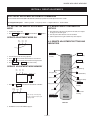
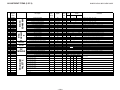
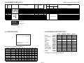
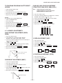
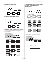
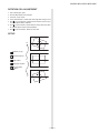
Self Diagnosis
Supported model
AA-2U CHASSIS
SERVICE MANUAL
MODEL NAME
KV-32FV27
KV-32FV27
KV-36FS13
KV-36FS13
KV-36FS13H
KV-36FS17
KV-36FS17H
KV-36FV27
KV-36FV27
KV-36FV27H
KV-38FS17
REMOTE COMMANDER
DESTINATION
CHASSIS NO.
RM-Y182
US
SCC-S44KA
RM-Y182
CND
SCC-S45GA
RM-Y180
US
SCC-S44HA
RM-Y180
CND
SCC-S45EA
RM-Y180
HAWAII
SCC-S46FA
RM-Y181
US
SCC-S44GA
RM-Y181
HAWAII
SCC-S46EA
RM-Y182
US
SCC-S44JA
RM-Y182
CND
SCC-S45FA
RM-Y182
HAWAII
SCC-S46GA
RM-Y181
E
SCC-S50EA
KV-36FV27
RM-Y182
TRINITRON® COLOR TELEVISION
9-965-901-01
KV-32FV27 / 36FS13 / 36FS17 / 36FV27/ 38FS17
SECTION 4: CIRCUIT ADJUSTMENTS
ELECTRICAL ADJUSTMENTS BY REMOTE COMMANDER
Use the Remote Commander (RM-Y180, RM-Y181, RM-Y182) to perform the circuit adjustments in this section.
Test Equipment Required: 1. Pattern generator 2. Frequency counter 3. Digital multimeter 4. Audio oscillator
4-1. SETTING THE SERVICE ADJUSTMENT
MODE
4-2. MEMORY WRITE CONFIRMATION
METHOD
1. Standby mode (Power off).
2. Press Display
Channel 5
1. After adjustment, pull out the plug from the AC outlet, then replace
the plug in the AC outlet again.
2. Turn the power switch ON and set to Service Mode.
3. Call the adjusted items again to confirm they were adjusted.
Sound Volume +
Power
SERVICE ADJUSTMENT MODE ON
Disp.
(Item)
Item
order
VP
HSIZ
Item
data
7
TV
0
4-3. REMOTE ADJUSTMENT BUTTONS AND
INDICATORS
SERVICE
Mode
MUTING
3.
4.
5.
6.
The CRT displays the item being adjusted.
Press 1 or 2 on the Remote Commander to select the item.
Press 3 or 6 on the Remote Commander to change the data.
Press MUTING then ENTER to write into memory.
POWER
(Enter into
memory
(Service Mode)
DISPLAY
(Service Mode)
3
Item (Data up)
SERVICE ADJUSTMENT MODE MEMORY
Disp.
(Item)
VP
HSIZ
Item
order
Item
data
7
TV
0
SERVICE
1
Disp. (Item up)
MUTING
2
(Device Item Up)
ENTER
VP
HSIZ
Item
order
0
ENTER
Disp. (Item down)
(Enter into
memory
8
(Initialize)
Item
data
7
TV
5
(Device item down)
4
Red
7. Press 8 then ENTER on the Remote Commander to initialize.
Disp.
(Item)
6
Item (Data down)
Green
0
(Remove from
memory)
WRITE
Carry out step 7 when adjusting
IDs 0 to 7 and when replacing and
adjusting IC002.
VOLUME (+)
(Service Mode)
RM-Y182
8. DO NOT turn off set until SERVICE appears.
— 15 —
KV-32FV27 / 36FS13 / 36FS17 / 36FV27 / 38FS17
4-4. ADJUSTMENT ITEMS (1 OF 6)
Description
Register
Name
Data
Adj/Fix
Range
Initial
32"
Data
FV
36"/38"
FS
Comments
FV
0-63
Adj
7
7
7
H-Size
0-63
Adj
10
10
10
EW DC bias, 0: -0.5V, 31: 0V, 63: +0.5V
AFC Bow
0-15
Adj
6
6
6
3
VANG
AFC Angle
0-15
Adj
5
5
5
4
Trapezium Adjustment
0-15
Adj
6
6
6
Pin Compensation
0-63
Adj
32
32
32
0: 0.15Vpp, 31: 0.7Vpp, 63: 1.3Vpp
Upper Corner Pin
0-63
Adj
36
36
36
0: -0.4V, 63: +0.4V
Lower Corner Pin
0-63
Adj
36
36
36
0: -0.4V, 63: +0.4V
11
TRAP
PAMP
UCPN
LCPN
VSIZ
VPOS
VLIN
VSCO
0: top/bottom delay 900ns, 7: center, 15: top/bottom advance 900ns
0: top delay/bottom advance 650ns, 7: center,
15: top advance/bottom delay 650ns
0: 1.5ms advance, 15: 1.5ms delay
12
VZOM
13
EHT
ASP
ASP1
SCRL
HBSW
LBLK
RBLK
HDW
EWDC
LVLN
UVLN
RDRV
GDRV
BDRV
RCUT
GCUT
BCUT
RDR4
GDR4
BDR4
RCU4
GCU4
BCU4
5
6
7
8
9
10
14
15
16
17
18
19
20
21
22
23
24
25
26
27
28
29
30
31
32
33
34
35
36
SBRT
37
RON
GON
BON
AXPL
CBPF
COFF
TSSP
TSPF
VSSP
VSPF
YSSP
38
39
40
41
42
43
44
45
46
47
VP
CXA2131AS
H-Position
2
HPOS
HSIZ
VBOW
0
1
0: 2ms delay, 63: 2ms advance
V-Size
0-63
Adj
0
0
0
0: -15%, 31: 0%, 63: +15%
V-Position
0-63
Adj
31
31
31
0: -0.1V, 31: 0V, 63: +0.1V
V-Linearity
0-15
Adj
7
7
7
0: 85% top enlarged, 7: 100% top normal, 15: 115% top compressed
S-Correction
0-15
Adj
7
7
7
16:9 CRT Zoom Mode On/Off
0,1
FIX
0
Vertical Size High Voltage Correction
0-15
FIX
4
4
0: 0V added to VD, 15: 100mVpp added to VD
0: Zoom Off, 1: Zoom On
(top/bottom cut by 25% when ASPECT=31, RGB blanked in this interval)
0: Picture adjusted 0%, 15: Picture Adjusted -5%
Aspect Ration Control 4:3 Mode
0-63
FIX
47
47
0: 75%(16x9 CRT Full), 31: 100%(4x3 CRT Full), 63: 110%
Aspect Ration Control 16:9 Mode
0-63
FIX
47
47
0: 75%(16x9 CRT Full), 31: 100%(4x3 CRT Full), 63: 110%
16:9 Vertical Scroll During Zoom
0-63
FIX
31
31
0: Scrolled toward top 32H, 63: Scrolled toward bottom 32H
H Blanking Switch
0,1
FIX
1
1
0: OFF, 1: ON
Left Blanking
0-15
FIX
15
15
0: +1.2ms, 7: Center, 15: -1.2ms
Right Blanking
0-15
FIX
0
0
0: +1.2ms, 7: Center, 15: -1.2ms
H Drive Pulse Width
0,1
FIX
1
1
0: Normal Mode (25ms), 1: Narrow Pulse Width
0
EW/DC Display 4x3 on 16x9 CRT
0,1
FIX
0
0
0: OFF, 1: ON
Picture Bottom Lin Adjust
0-15
Adj
0
0
0: 100%, 15: 85% Picture top compressed
Picture Top Lin Adjust
0-15
Adj
0
0
Red Drive
0-63
Adj
31
Green Drive
0-63
Adj
31
31
0: 1.5Vpp, 63: 3.0Vpp Greem Signal Output
Blue Drive
0-63
Adj
31
31
0: 1.5Vpp, 63: 3.0Vpp Blue Signal Output
Red Cutoff
0-15
FIX
7
14
0: 3.5mA IK, 7: 13mA IK, 15: 22.7mA IK
Green Cutoff
0-15
Adj
7
7
0: 3.5mA IK, 7: 13mA IK, 15: 22.7mA IK
Blue Cutoff
0-15
Adj
7
7
Video 4 Red Drive
0-63
Adj
31
Video 4 Green Drive
0-63
Adj
31
31
0: 1.5Vpp, 63: 3.0Vpp Greem Signal Output
Video 4 Blue Drive
0-63
Adj
31
31
0: 1.5Vpp, 63: 3.0Vpp Blue Signal Output
Video 4 Red Cutoff
0-15
FIX
7
14
0: 3.5mA IK, 7: 13mA IK, 15: 22.7mA IK
Video 4 Green Cutoff
0-15
Adj
7
7
0: 3.5mA IK, 7: 13mA IK, 15: 22.7mA IK
Video 4 Blue Cutoff
0-15
Adj
7
7
0: 3.5mA IK, 7: 13mA IK, 15: 22.7mA IK
Sub Brightness
0-31
Adj
15
31
54
31
adjust to
IRE
cutoff
0: 100%, 15: 85% Picture bottom compressed
48
0: 1.5Vpp, 63: 3.0Vpp Red Signal Output
0: 3.5mA IK, 7: 13mA IK, 15: 22.7mA IK
0: 1.5Vpp, 63: 3.0Vpp Red Signal Output
54
adjust to IRE cutoff
Sub Brightness
Red Off
0,1
FIX
1
1
0:OFF, 1:ON
Green Off
0,1
FIX
1
1
0:OFF, 1:ON
Blue Off
0,1
FIX
1
1
0:OFF, 1:ON
Axis PAL
0,1
FIX
0
0
0: Normal Axis, 1: Forced PAL Asix
Chroma BPF On/Off
0,1
FIX
1
1
0: BPF OFF, 1: BPF ON
Color On/Off
0,1
FIX
0
0
0: Chroma OFF, 1: Chroma ON
Sub Sharpness for TV Input
0-15
Fix by model
6
Sharpness fo for TV Input
0,1
FIX
1
Sub Sharpness for Video Input
0-15
Fix by model
7
Sharpness fo for Video Input
0,1
FIX
1
Sub Sharpness for YUV Input
0-15
Fix by model
7
— 16 —
6
5
6
0=-12dB, 7=+3.5dB, 15=+9dB
7
0=-12dB, 7=+3.5dB, 15=+9dB
0=2.5MHZ, 1=3.0MHz
1
7
5
7
6
0=2.5MHZ, 1=3.0MHz
1
7
0=-12dB, 7=+3.5dB, 15=+9dB
KV-32FV27 / 36FS13 / 36FS17 / 36FV27 / 38FS17
ADJUSTMENT ITEMS (2 OF 6)
Description
Register
Name
62
BKOF
AGN2
SREF
BBLP
BBHP
SVOL
SBAL
SBAS
STRE
SPCA
CENA
INPA
COUT
YAPS
NSDS
MSS
EXAD
PECS
EXCS
CPP
HDP
CDL
DYCO
DYGA
DCCO
DCGA
YNRK
YNRI
YNRL
CNRK
CNRI
CNRL
ID1O
ID1W
ID1N
CLK
52
53
54
55
56
57
58
59
63
0
1
2
3
4
5
6
0
1
2
0
1
2
3
4
5
6
7
8
9
10
11
12
13
14
15
16
17
18
19
20
21
22
23
VP
CXA2131AS
VBSW
51
AP
BH3868
61
50
Adj/Fix
Range
SRS
TDA7464
3D COMB
uPD64082
60
YSPF
AXNT
PREL
DCT
ABLM
FSC
HOSC
VSS
HSS
HMSK
VTMS
AFC
REFP
48
49
Data
Initial
32"
Data
FV
36"/38"
FS
Comments
FV
Sharpness fo for YUV Input
0,1
FIX
1
1
0=2.5MHZ, 1=3.0MHz
Axis NTSC
0,1
FIX
0
0
0: Japan Axis, 1: US Axis
Pre/Overshoot Ratio
0,1
FIX
1
1
0: 1:1, 1: 2:1
DC Transmission Ratio
0,1
FIX
1
1
0:100%, 1:85%
0:Picture ABL, 1:Picture/Brightness ABL
ABL Mode
0,1
FIX
1
1
FSC Output On/Off
0,1
FIX
1
1
0: FSC output OFF, 1: FSC output ON
H VCO Frequency Adjustment
0-15
FIX
12
12
0: Low, 15: High (40 Hz Steps)
0: 1/3 from sync tip, 1: 1/4 from sync tip
Vsync Slice Level
0,1
FIX
0
1
Hsync Slice Level
0,1
FIX
0
1
0: 1/3 from sync tip, 1: 1/4 from sync tip
Macrovision Countermeasure
0,1
FIX
1
1
0: Off, 1: ON
Select Signal VTIM Pin
0-3
FIX
0
0
0: V retrace timing, 1: Hsync signal, 2: Vsync signal, 3: don't use
AFC
0-3
FIX
0
0
0: High Gain, 1: Medium Gain, 2: don’t use, 3: Extremely low gain
REFP
0,1
FIX
0
0
VBLK Width Control
0-3
FIX
0
0
ABL Signal Detection Level
0,1
FIX
0
0
0: R=20H/G=21H/B=22H, 1: R=23H/G=24H/B=25H
0: 9H from B, 1: 10H from B, 2: 11H from B, 3:12H from B
(When JUMP SW=1)
0: VTH=3V, 1: VTH=1V
Aging Mode 2 - Black Output Mode
0,1
FIX
0
0
0: Black Output Mode OFF, 1: Black Output Mode ON
Surround Effect
0-15
FIX
7
7
0: Min, 15: Max (8-15 LOOP=1)
BBE Low PAss
0-15
FIX
5
5
0: 0.5dB, 15: 10dB
BBE High Pass
0-15
FIX
3
3
0: 0.5dB, 15: 10dB
Sub Volume
0-15
FIX
7
7
0:-0 volume steps, 15:-15 volume steps
Sub Balance
0-15
FIX
7
Sub Bass
0-15
Fix by model
5
5
8
5
8
0: +Right, 15:+Left
7
5
0:-7 steps, 15: +8 steps
5
0:-7 steps, 15: +8 steps
Sub Treble
0-15
Fix by model
3
SRS Space Attenuation
0-63
FIX
0
0
0: 0dB, 63: -31db (1dB steps)
SRS Center Attenuation
0-63
FIX
0
0
0: 0dB, 63: -31db (1dB steps)
Input Attenuation
0-127
FIX
3
3
0: 0dB, 127: -31.5dB (0.5dB steps)
Chroma Signal Gain / BPF
0-3
FIX
3
3
Input/Output gain=1 / BPF ON
Y V-Compensation/Peaking
0-3
FIX
3
3
Correctin enabled for digital/analog inputs
Standard/Non-Standard Processing
0-3
FIX
0
0
Standard adaptive processing
Inter-frame/Inter-line Mode
0-3
FIX
0
0
Adaptive Processing
External ADC Insert
0,1
FIX
0
0
Internal Y-ADC
Pedestal Error Correction
0-3
FIX
0
0
Standard
C sync Input
0-3
FIX
1
1
Use CSI
Y ADC Amplitude/Clamp Method
0-3
FIX
0
0
Y-ADC & C-ADC Vtb=1.25V
H Phase Fine Adjustment
0-7
FIX
3
3
Phase +/- 0msec
C Output Delay Fine Adjustment
0-7
FIX
5
5
Y/C Delay +/- 0msec
Y Moving Coring Level
0-15
FIX
2
2
0: Close to moving pictures, 15: Close to still pictures
Y Moving Coring Gain
0-15
FIX
10
10
0: Close to still Pictures, 15: Close to moving Pictures
C Moving Coring Level
0-15
FIX
2
2
0: Close to moving pictures, 15: Close to still pictures
C Moving Coring Gain
0-15
FIX
9
9
0: Close to still Pictures, 15: Close to moving Pictures
YNR Non-linear Filter Gain
0,1
FIX
1
1
x7/8 large noise reduction and large after image
YNR Non-linear Filter Convergence
0,1
FIX
0
0
6LSB small noise reduction and small after image
YNR Non-linear Filter Limit Level
0-3
FIX
1
1
0: YNR Off , 3: 3LSB large noise reduction
CNR Non-linear Filter Gain
0,1
FIX
1
1
x7/8 large noise reduction and large after image
CNR Non-linear Filter Convergence
0,1
FIX
0
0
6LSB small noise reduction and small after image
CNR Non-linear Filter Limit Level
0-3
FIX
1
1
0: CNR OFF , 3: 3LSB large noise reduction
ID-1 Superimpose Signal
0,1
FIX
0
0
Through, no superimposition
Specifies bit A1 of Word 0
0,1
FIX
0
0
0: 4x3, 1: 16x9
Spedifies bit A2 of Word 0
0,1
FIX
0
0
0: normal, 1:letterbox
CLK8 Pin Output
0,1
FIX
1
1
0: Output 8fsc, 1: Output OFF
— 17 —
KV-32FV27 / 36FS13 / 36FS17 / 36FV27 / 38FS17
ADJUSTMENT ITEMS (3 OF 6)
Description
Register
Name
26
27
28
29
30
31
32
33
34
35
36
37
38
39
40
41
42
43
44
45
46
47
48
49
50
51
52
53
54
55
56
57
58
59
60
61
62
63
64
65
66
0
1
2
3
4
5
6
Adj/Fix
Range
3D COMB
uPD64082
25
ST0S
WSC
VTRH
VTRR
LDSR
PWRE
VAPG
VAPI
TEST
YPFT
YPFG
V1PS
VEGS
CC3N
C0HS
CLPH
SEL2
SEL1
YHCO
YHCG
OVST
CSHD
KCTT
SHT
VCT
OTT
CL2D
CGGT
CLEB
CGT
HPLL
BPLL
FSCF
PLLF
KILR
HSSL
VSSL
BGPS
BGPW
ADCL
ADPD
NSDW
CNRF
SHPR
BLAD
SRTS
YNR
GIRE
DAC1
DAC2
PIC IMP
TA1226
N
24
Data
Initial
32"
Data
FV
36"/38"
FS
Comments
FV
Select ST0 Pin Output Signal
0-3
FIX
1
1
Noise Detection Coring
0-3
FIX
1
1
External Y-ADC clamp pulse
1LSB coring for noise detection circuit
H-sync Non-Standard Detection Hysteresis
0-3
FIX
1
1
Low hysteresis (2 clock pulses)
H-sync Non-Standard Detection Sensitivity
0-3
FIX
1
1
Medium sensativity (+/- 8 clock pulses)
Frame Sync Non-Std Detection Sensativity
0-3
FIX
2
2
Low sensativity (1.5 clock pulses)
Internal ADC Input Range
0,1
FIX
0
0
Same input range on Y-ADC and C-ADC
Vertical Aperture Compensation Gain
0-7
FIX
4
4
0: Correction OFF, 7: Max Correction
Vertical Aperture Comp Convergence
0-31
FIX
12
12
0: Correction OFF, 31: Max Correction
Test Bit
0,1
FIX
0
0
Normal Mode
Y Peaking Filter Center Frequency
0-3
FIX
3
3
4.22 MHz
Y Peaking Filter Gain
0-15
FIX
7
6
0: -1 gain, 15: 0.875 gain
Horizontal Dot Supression Level
0-3
FIX
2
2
Medium suppression
Vertical Dot Supression Level
0-3
FIX
2
2
Medium supression
Line Comb C Separation Filter
0,1
FIX
0
0
Narrow bandwidth
C Signal Delay Time at NR
0,1
FIX
0
0
1H Delay
Y-ADC Clamp Test Bit
0,1
FIX
0
0
Normal Mode
DC Detection High Freq Sensativity
0,1
FIX
0
0
Low sensativity, Close to still pictures
DY detection Low Freq Sensativity
0,1
FIX
0
0
Low sensativity, Close to still pictures
Y High Freq Coring
0-3
FIX
1
0
Small Amount of coring (+/- 1LSB)
Y High Freq Coring Gain
0,1
FIX
0
0
Gain = 1
Non Standard Detection Test Bit
0,1
FIX
0
0
Normal Mode
H/V counter Test Bit
0,1
FIX
0
0
Normal Mode
H/V counter Test Bit
0-3
FIX
0
0
Normal Mode
Non Standard Detection Test Bits
0,1
FIX
0
0
Normal Mode
H/V counter Test Bit
0,1
FIX
0
0
Normal Mode
H/V counter Test Bit
0,1
FIX
0
0
Normal Mode
Clock Generator Test Bit
0,1
FIX
1
1
Normal Mode
Clock Generator Test Bit
0,1
FIX
0
0
Normal Mode
Clock Generator Test Bit
0,1
FIX
0
0
Normal Mode
Clock Generator Test Bit
0,1
FIX
0
0
Normal Mode
Horizontal PLL Filter
0,1
FIX
1
1
Quick convergence
Burst PLL Filter
0,1
FIX
1
1
Quick convergence
Burst Extraction Gain
0,1
FIX
0
0
High gain
PLL Loop Gain
0,1
FIX
1
1
High gain, quick convergence
Killer Detection Reference
0-15
FIX
3
3
0: Detection off, 15: High detection sensativity
Horizontal Sync Slice Level
0-15
FIX
12
12
0: 4LSB, 15: 19LSB
0: HSSL + 0LSB, 15: HSSL + 15LSB
Vertical Sync Slice Level
0-15
FIX
8
8
Burst Gate Start Position
0-15
FIX
5
5
0: Hsync center + 2ms, 15: Hsync center +5.75ms
Internal Burst Gate Pulse Width
0-15
FIX
10
10
0: 0.5ms, 15: 4.25ms
0: 0ns, 3: 20.5ns (typical)
ADC Clock Delay
0-3
FIX
3
3
ADC Power Down
0,1
FIX
1
1
Stop ADC when not in use
Non Standard Detection Test Bit
0,1
FIX
0
0
Normal Mode
CNR Section Test Bit
0,1
FIX
0
Controls both DL APACON and SRT
0-127
Fix by Model
52
Normal Mode
0
52
59
52
0: Minimum, 127: Maximum
Black Area Detect
0-3
FIX
0
0
0: 10IRE, 1: 20IRE, 2: 30IRE, 3: 40IRE
SRT Start Amplitude
0-3
FIX
3
3
0: 7IRE, 1: 10IRE, 2: 14IRE, 3: 28IRE
Controls YNR ON/OFF
0,1
FIX
1
1
YNR ON
Gamma Correction Start Point
0-3
FIX
3
3
0: 70IRE, 1: 80IRE, 2: 90IRE, 3: OFF
1 bit DAC Output
0,1
FIX
0
0
Open
1 bit DAC Output
0,1
FIX
0
0
Open
— 18 —
KV-32FV27 / 36FS13 / 36FS17 / 36FV27 / 38FS17
ADJUSTMENT ITEMS (4 OF 6)
Description
Register
Name
VERB
8
9
10
11
12
0
1
2
3
4
5
12
PSEL
SELD
4SLD
PCOR
AGCR
13
AGCM
14
AGCV
CLMD
CLMS
LMOF
PYDL
FRMY
FRSL
FRWH
FRWV
PBSW
CKIL
COLO
PSHU
4PSU
CPLL
SCAD
PCON
4PCN
PBRT
4PBR
IPER
4IPR
IPEG
4IPG
IPEB
4IPB
BLKR
BLKB
PVGA
4PVG
9
10
11
15
16
17
18
19
20
21
22
23
0
1
2
3
4
5
6
7
8
9
10
11
12
13
14
15
16
17
18
19
PIC IMP
TA1226N
PIP
SDA9588X
7
8
Adj/Fix
Range
PIP-YC
SDA9588X
6
GCUR
BLKC
TEST
RS
RTC
VMLO
PIPH
PIPV
POFV
POFH
VACQ
HACQ
PVID
7
Data
Initial
32"
Data
FV
36"38"
FS
Comments
FV
Controls Curve of Gamma Correction
0,1
FIX
0
0
0: -2.4dB, -1.6dB
Black Conpensation
0,1
FIX
1
1
OFF
Test Bit
0-3
FIX
3
3
Pin 20 Output: 0=RS, 1=SHR, 2=RTC, 3=TEST3
Gain of DL APACON at 8MHz Peak
0-7
FIX
0
0
0: 0dB, 7: +6dB
Compensation Ratio of SRT and DL APACON
0-7
FIX
4
4
0: Min, 7: Max
Gain for Menu VM=LOW
0-2
FIX
1
1
0=off, 1=-6dB, 2=-3dB, 3=0dB
PIP H-position
0-127
FIX
34
36
0:Right, 127:Left
PIP V-position
0-63
FIX
22
22
0:Up, 63:Down
Position Ofset Vertical
0-15
FIX
4
4
Vertical PiP Offset from Center
Position Ofset Horizontal
0-31
FIX
17
18
Horizontal PiP Offset from Center
PiP V-Acquisition Window
0-15
FIX
8
8
0: -8 lines up, 8: Center, 15: +7 pixels down
PiP H-Acquisition Window
0-15
FIX
8
8
0: -16 pixels right, 8: Center, 15: +14 pixels left
PiP Vsync Delay
0-31
FIX
0
0
Vertical Blanking
0,1
FIX
0
0
SELDOWN Bit Control
0,1
FIX
1
1
Step size 3.56ms< 1 step < 6.4ms
0: DAC Blanking during line blanking interval,
1: DAC Blanking during line AND field intervals
0:Open out, 1:TTL out
Select PYS Delay
0-15
FIX
8
8
0: -8 clock cycles, 8: NO delay, 15: +7 clock cycles
Select PYS Delay YUV Input
0-15
FIX
8
8
0: -8 clock cycles, 8: NO delay, 15: +7 clock cycles
Position Correction
0,1
FIX
1
1
0: OFF, 1: ON (Position correction during varying parent frequency)
AGC Gain Control Reset
0,1
FIX
1
1
AGC Mode
0-3
FIX
0
3
12
0: Normal, 1: Reset (transition of 0-->1 resets AGC)
0: Sync height & ADC Overflow, 1: sync height,
2: ADC overflow, 3: AGC Fixed
0: Input valtage 0.5Vpp, 15: Input Voltage is 1.5Vpp
ADC Value
0-15
FIX
11
Clamp Pulse Duration
0-3
FIX
0
0
0: 0.5ms, 1: 0.9ms, 2: 1.2ms, 3: 1.5ms
Clamp Pulse Start
0-3
FIX
2
2
0: 1.0ms, 1: 1.5ms, 2: 2.0ms, 3: 2.5ms
Luminance Offset
0-3
FIX
3
3
0: NO OFFSET, 1: +16LSB, 2: -8LSB, 3: -16LSB
Y/C Delay
0-15
FIX
8
2
Frame Y Level
0-15
Fix by Model
6
4
0: -8 pixels, 15: +7 pixels
5
Adjusts 4 MSB of Frame Y Signal
Frame Type Select
0,1
FIX
1
1
0: Normal frame, 1: 3D frame
Frame Width Horizontal
0-7
FIX
4
4
0: No frame, 7: 7 pixels
Frame Width Vertical
0-3
FIX
1
1
0: No frame, 3: 3 lines
PiP Block Selection (PIPBG vs PIPBLK)
0,1
FIX
0
1
Blocking Type: 0= PIPBG(gray), 1=PIPBLK(black)
Color Killer Threshold
0-3
FIX
0
0
0: -30dB, 1: -18dB, 2: -24dB, 3: color always off
Color Killer Off
0,1
FIX
0
0
0: Color killer active, 1: Color always on
PiP Sub Hue
0-15
FIX
7
7
PiP sub hue
PiP Sub Hue YUV Input
0-15
FIX
7
7
PiP sub hue
Chroma PLL Off
0,1
FIX
0
0
0: Chroma PLL active, 1: Chroma PLL free running
Sub Carrier Freq Fine Adjustment
0-31
FIX
6
6
0: -150 PPM, 7: default, 31: +310 PPM
PiP Contrast
0-15
FIX
0
0
0: nominal, 15: +30% increase
PiP Contrast YUV Input
0-15
FIX
0
0
0: nominal, 15: +30% increase
PiP Brightness
0-15
FIX
2
2
0: nominal, 15: +20% increase
PiP Brightness YUV Input
0-15
FIX
2
2
0: nominal, 15: +20% increase
V Pedestal
0-15
FIX
0
0
0: nominal, 15: +15LSB offset
V Pedestal YUV Input
0-15
FIX
4
0
0: nominal, 15: +15LSB offset
Y Pedestal
0-15
FIX
0
0
0: nominal, 15: +15LSB offset
Y Pedestal YUV Input
0-15
FIX
0
0
0: nominal, 15: +15LSB offset
0: nominal, 15: +15LSB offset
U Pedestal
0-15
FIX
1
1
U Pedestal YUV Input
0-15
FIX
1
1
0: nominal, 15: +15LSB offset
Invert V Pedestal
0,1
FIX
1
0
0: Offset add during blanking, 1: Offset add during active
Invert U Pedestal
0,1
FIX
0
1
0: Offset add during blanking, 1: Offset add during active
Peak Level V Output
0-255
FIX
84
84
0: 0.3Vpp, 192: 1.0Vpp, 255: 1.2Vpp
Peak Level V Output YUV Input
0-255
FIX
69
69
0: 0.3Vpp, 192: 1.0Vpp, 255: 1.2Vpp
— 19 —
KV-32FV27 / 36FS13 / 36FS17 / 36FV27 / 38FS17
ADJUSTMENT ITEMS (5 OF 6)
Description
Register
Name
0
DUM1
VOSD
DISP
RAMW
ICMP
IPOR
FAWD
TILT
24
25
26
27
28
29
0
1
2
3
4
5
6
1
0
1
2
3
4
5
0
VPIC
1
VBRT
2
VCOL
3
VSHP
4
VVM
5
VTRI
6
VGMA
7
VBLK
8
9
10
VAPA
VSRT
VNRM
PIP-YC
SDA9588X
LNJ1
23
DAC
CXA131
5
1
22
Adj/Fix
Range
Initial
32"
Data
FV
36"/38"
FS
Comments
FV
Peak Level U Output
0-255
FIX
52
52
Peak Level U Output YUV Input
0-255
FIX
36
36
0: 0.3Vpp, 192: 1.0Vpp, 255: 1.2Vpp
Peak Level Y Output
0-255
Fix by Model
104
25
Peak Level Y Output YUV Input
0-255
Fix by Model
129
27
UV Output Polarity
0,1
FIX
0
0
Color Saturation Adjustment
0-15
FIX
8
9
0: No color, 8: nominal saturation, 15: nominal x 1.875
Y Peaking Adjustment
0-7
FIX
7
7
0: No peaking, 7: Strongest Peaking
0: 0.3Vpp, 192: 1.0Vpp, 255: 1.2Vpp
35
0: 0.3Vpp, 192: 1.0Vpp, 255: 1.2Vpp
37
0: 0.3Vpp, 192: 1.0Vpp, 255: 1.2Vpp
0: +U/+V output, 1: -U/-V output
Y Peaking Adjustment YUV Input
0-7
FIX
7
7
0: No peaking, 7: Strongest Peaking
Y Coring Enable
0,1
FIX
1
1
0: OFF, 1: ON
Clamp Pulse Length
0-3
FIX
0
0
0=5ms, 1=3.75ms, 2=2.5ms, 3=1.25ms
Rotation Coil
0-63
FIX
31
31
Rotation coil adjustment for nominal value
Sub Color TV Input
0-7
Adj
120
120
111
106
TV Sub Color Adjustment (CXA2039 YUV Models AT DAC)
Sub Color Video Input
0-7
Adj
120
120
122
114
VIDEO1-3 Sub Color Adjustment (CXA2039 YUV Models at DAC)
Sub Color YUV Input
0-7
Adj
120
120
117
YUV Sub Color Adjustment (CXA2039 YUV Models at DAC)
Sub Hue TV Input
0-7
Adj
15
15
16
TV Sub HUE Adjustment (CXA2039 YUV Models at DAC)
Sub Hue Video Input
0-7
Adj
15
15
18
VIDEO1-3 Sub HUE Adjustment (CXA2039 YUV Models at DAC)
Sub Hue YUV Input
0-7
Adj
15
15
16
YUV Sub HUE Adjustment (CXA2039 YUV Models at DAC)
ID1
CXD2085
Decoding Result Held For VCR Scanning
0,1
FIX
0
0
ID-1 Signal Location
0,1
FIX
0
0
CCD
CCD Dummy Register
OP
M306V5
PROGRAM
PALETTE
0
PUGA
4PUG
PYGA
4PYG
CHRO
SATA
YPKG
4YPK
YCOR
CLPL
RTCO
T2CO
V2CO
4COL
T2HU
V2HU
4SHU
XJGL
20
21
Data
Hold data during VCR variable speed playback
Search for ID-1 data +/- one line in VBI
Used to display CC data in Service Mode
VChip OSD Test Register
0,1
FIX
0
0
Used to display VChip data in Service Mode
OSD Position
0-63
Adj
15
15
OSD horizontal position
0
OSD RAM Window
0,1
FIX
0
OSD Non-interlace Threshold
0-15
FIX
4
4
0: 0 fields, 15: 15 fields
OSD Non-interlace Even/Odd Display
0-3
Fix
1
1
0=Even OSD display, 1= Odd OSD display, 2&3=N/A
Factory AutoWide Mode
0,1
Fix
0
0
0= No Autowide in RF mode, 1= Autowide in RF Mode
Tilt Correction Spec
0,1
Fix
0
PROGRAM FOR EACH PALETTE MODE
Set Current Program Pallette
PICTURE Reset Level
Set Current Program Pallette
BRIGHTNESS Reset Level
Set Current Program Pallette
COLOR Reset Level
Set Current Program Pallette
SHARPNESS Reset Level
Set Current Program Pallette
VM Reset Level
Set Current Program Pallette
Color Temp Reset Setting
Set Current Program Pallette
YC/J GAMMA
Set Current Program Pallette
Black Stretch
Set Current Program Palette APACON
Set Current Program Pallette SRT
Set Current Program Pallette NRMD
VIVID
2
STD MOVIE
0= New Tilt Spec for AA2U (less VANG offset), 1= AA2W/AA2H Tilt Spec
SPORTS
0-63
FIX by Palette
50
63
50
38
63
0=MIN, 63=MAX
0-63
FIX by Palette
31
31
31
31
31
0=MIN, 63=MAX
0-63
FIX by Palette
31
38
31
31
38
0=MIN, 63=MAX
0-63
FIX by Palette
31
31
31
31
31
0=MIN, 63=MAX
0-3
FIX by Palette
1
2
1
0
2
0=OFF, 1=LOW, 2=HIGH, 3=N/A
0-3
FIX by Palette
1
0
1
2
0
0=COOL, 1=NEUTRAL, 2=WARM, 3=N/A
0-3
FIX by Palette
2
3
2
2
2
0=GAMMA CORRECTION OFF, 3=+12 IRE CORRECTION @ 40 IRE INPUT
0,1
FIX by Palette
1
1
1
1
1
0=BLACK STRETCH OFF, 1=BLACK STRETCH ON
0,1
0,1
0,1
FIX by Palette
FIX by Palette
FIX by Palette
1
0
0
0
1
0
1
0
0
1
0
0
1
0
1
0=APACON OFF, 1=APACON ON
0=SRT OFF, 1=SRT ON
0=3D YCS, 1=2D YCS
— 20 —
KV-32FV27 / 36FS13 / 36FS17 / 36FV27 / 38FS17
ADJUSTMENT ITEMS (6 OF 6)
Description
Register
Name
Adj/Fix
Range
ID
MAP
RDOF
GDOF
BDOF
RCOF
GCOF
BCOF
DCOF
ID-0
ID-1
ID-2
ID-3
ID-4
ID-5
ID-6
ID-7
WARM
COLOR
TEMP
OFFSET
0
1
2
3
4
5
6
0
1
2
3
4
5
6
7
Data
VALUE
VALUE
Red Drive offset for WARM
Green Drive offset for WARM
Blue Drive offset for WARM
Red Cutoff offset for WARM
Green Cutoff offset for WARM
Blue Cutoff offset for WARM
Dynamic Color setting for WARM
ID-0 (Language/Color Systems)
ID-1 (Input/Output Conifguration)
ID-2 (Audio)
ID-3 (OSD/Timer/V-chip/Ch Fix)
ID-4 (CC/Spot Killer/etc)
ID-5 (V-series Features/etc)
ID-6 (PiP/Ant Sw related)
ID-7 (Special Models/etc)
0-63
0-63
0-63
0-31
0-31
0-31
0,1
0-255
0-255
0-255
0-255
0-255
0-255
0-255
0-255
Initial
32"
Data
FV
FIX
FIX
FIX
FIX
FIX
FIX
FIX
Fix by model
Fix by model
Fix by model
Fix by model
Fix by model
Fix by model
Fix by model
Fix by model
FS
0
4
15
0
2
7
0
89
63
239
99
139
181
6
24
Comments
FV
0
4
15
0
2
7
0
refer to NVM ID Chart
Red Drive MOVIE=RDRV(RDR4)-RDOF
Green Drive MOVIE=GDRV(GDR4)-GDOF
Blue Drive MOVIE=BDRV(BDR4)-BDOF
Red Cutoff MOVIE=RCUT(RCU4)-RCOF
GREEN Cutoff MOVIE=GCUT(GCU4-GCOF)
BLUE Cutoff MOVIE=BCUT(BCU4)-BCOF
0=OFF, 1=ON
See ID map
See ID map
See ID map
See ID map
See ID map
See ID map
See ID map
See ID map
= Not Used for AA-2U
= Fixed Item For AA-2U
4-6. PROGRAM PALETTE SETTINGS
4-5. FEATURE ID MAP
ID
ID7
7
24
TV
SERVICE
00011000
Picture
Brightnness
Color
Sharpness
VM1)
1)
C Temp
Gamma
Blk Comp
V Apa Comp
SRT ON/OFF
NRMD
NVM:G
M306V5ME-1015P
VERSION: 1.0__
Note: Check to be sure NVM is good (NVM: G)
0RGHO
'HVWLQDWLRQ
.9)9
86
.9)9
&1'
.9)6
86
.9)6
&1'
.9)6
+$:$,,
.9)6
86
.9)6
+$:$,,
.9)9
86
.9)9
&1'
.9)9
+$:$,,
.9)6
(
36"/38"
,'
,'
,'
,'
,'
,'
,'
,'
1)
— 21 —
(VPIC)
(VBRT)
(VCOL)
(VSHP)
(VVM)
(VTRI)
(VGMA)
(VBLK)
(VAPA)
(VSRT)
(VNRM)
Vivid
63
31
38
31
2
2
3
1
0
1
0
Standard
50
31
31
31
1
1
2
1
1
0
0
Setting of 3 is invalid for these registers
Movie
38
31
31
31
0
0
2
1
1
0
0
Sports
63
31
38
31
2
2
2
1
1
0
1
KV-32FV27 / 36FS13 / 36FS17 / 36FV27 / 38FS17
TO PROGRAM PROGRAM PALETTE RESET
LEVELS
SUB HUE, SUB COLOR ADJUSTMENT
(T2HU, T2CO, V2HU, V2CO, 4SHU, 4COL)
1.
2.
3.
4.
5.
Note:
Switch to Program Palette to edit.
Enter Service Mode.
Set desired values for current Program Palette settings.
Write into memory by pressing MUTING then ENTER .
Repeat steps 1-4 for each palette.
Example
To Set RESET Level of Standard Mode to 60%
1. Switch to STANDARD Palette.
2. Enter Service Mode.
3. Change value of VPIC to 38 (38/63 = 60%)
4. Write into memory by pressing MUTING then ENTER .
5. Enter Video Menu and press RESET .
6. Reset level of picture for STANDARD PALETTE ONLY is now 38
steps.
T2HU and T2CO are for Tuner inputs.
V2HU and V2CO are for all other Video inputs.
4SHU and 4COL are for Video 4 input.
1. Input a 75% color-bar signal.
2. Set to Service Adjustment Mode and set: VIDEO mode = Standard,
PICTURE = 100%, COLOR = 50%, HUE = 50%.
3. Connect an oscilloscope to Pin 3 of CN351 on the A Board.
4. Select T2HU and T2CO with 1 and 4 .
5. Adjust with 3 and 6 for a flat ± 50mV.
6. Write into memory by MUTING then ENTER .
7. Repeat steps 1-6 for V2HU & V2C0 and 4SHU & 4COL.
V1 V2 V3 V4
4-7. A BOARD ADJUSTMENTS
SUB CONTRAST ADJUSTMENT (RDRV,
RDR4)
1. Input a 75% color-bar signal.
2. Set to: VIDEO mode = Standard, COLOR = Minimum,
PICTURE = 100%, GON = 0 (OFF), BON = 0 (OFF)
3. Set to Service Adjustment Mode and connect an oscilloscope to
pin 1 of CN351 on the A Board.
4. Set RDRV with 1 and 4 .
5. Adjust with 3 and 6 for: 1.85 ± 0.05 Vp-p (KV-32FV27 ONLY),
1.95 ± 0.05 Vp-p (ALL EXCEPT KV-32FV27).
6. Write into memory by pressing MUTING then ENTER .
7. Repeat steps 1-6 for RDR4 using Video 4 input.
V. SIZE ADJUSTMENT (VSIZ)
1.
2.
3.
4.
5.
Input a cross-hatch signal.
Set to Service Adjustment Mode.
Select VSIZ with 1 and 4 .
Adjust with 3 and 6 for the best vertical size.
Write into the memory by pressing MUTING then ENTER .
White
1.95 ± 0.05 Vp-p (ALL EXCEPT KV-32FV27)
1.85 ± 0.05 Vp-p (KV-32FV27 ONLY)
Black
SUB BRIGHT ADJUSTMENT (SBRT)
1.
2.
3.
4.
5.
Set to Service Adjustment Mode.
Input a gray scale pattern signal.
Set the PICTURE to minimum, and BRIGHT to normal.
Select SBRT with 1 and 4 .
Adjust SUB BRIGHT level with 3 and 5 so that the stripe second
from the right is faintly visible.
6. Write into the memory by pressing MUTING then ENTER .
V. POSITION ADJUSTMENT (VPOS)
1.
2.
3.
4.
5.
white
second from the right
black
— 22 —
Input a cross-hatch signal.
Set to Service Adjustment Mode.
Select VPOS with 1 and 4 .
Adjust with 3 and 6 for the best vertical center.
Write into the memory by pressing MUTING then ENTER .
KV-32FV27 / 36FS13 / 36FS17 / 36FV27 / 38FS17
H. SIZE ADJUSTMENT (HSIZ)
1.
2.
3.
4.
5.
V ANGLE (VANG), V BOW (VBOW), UPPER
PIN (UPIN) AND LOW PIN (LPIN)
ADJUSTMENTS
Input a monoscope signal.
Set to Service Adjustment Mode.
Select HSIZ with 1 and 4 .
Adjust with 3 and 6 for the best vertical size.
Write into the memory by pressing MUTING then ENTER .
1.
2.
3.
4.
5.
Input a monoscope signal.
Set to Service Adjustment Mode.
Select VANG, VBOW, UPIN, and LPIN with 1 and 4 .
Adjust with 3 and 6 for the best picture.
Write the memory by pressing MUTING then ENTER .
V ANGLE (VANG)
H. POSITION ADJUSTMENT (HPOS)
HPOS Range is from 0~15.
1. Input a monoscope signal.
2. Set the Service Adjustment Mode.
3. Select HPOS with 1 and 4 .
4. Adjust with 3 and 6 for the best horizontal center.
5. Write into the memory by pressing MUTING then ENTER .
V BOW (VBOW)
UPPER PIN (UPIN)
LOW PIN (LPIN)
V LINEARITY (VLIN), V CORRECTION (VSCO),
PIN AMP (PAMP) AND PIN PHASE (PPHA)
ADJUSTMENTS
1.
2.
3.
4.
5.
Input a cross-hatch signal.
Set to Service Adjustment Mode.
Select VLIN, VSCO, PAMP, and PPHA with 1 and 4 .
Adjust with 3 and 6 for the best picture.
Write the memory by pressing MUTING then ENTER .
V LINEARITY(VLIN)
OSD POSITION ADJUSTMENT (DISP)
1.
2.
3.
4.
5.
VS CORRECTION (VSCO)
Input a color-bar signal.
Set to Service Adjustment Mode.
Select DISP with 1 and 4 .
Adjust with 3 and 6 for adjustment of characters to center.
Write the memory by pressing MUTING then ENTER .
OP
DISP
PIN AMP (PAMP)
PIN PHASE (PPHA)
— 23 —
0
16
TV
Service
KV-32FV27 / 36FS13 / 36FS17 / 36FV27 / 38FS17
ROTATION COIL ADJUSTMENT
1.
2.
3.
4.
5.
Input a monoscope signal.
Push the Menu button on the Remote.
Select the “Set-up” mode.
Select “Tilt Correction”. Confirm that number (0) color changes to red.
Push
(+) on the Remote. Confirm that the number increases up to
+5 and the picture rotates clockwise.
6. Push (-) on the Remote. Confirm that the number decreases down
to -5 and the picture rotates counter-clockwise.
7. Push (+) on the Remote. Return the value to 0.
SET-UP
+5
Channel Set-up
Favorite Channel
Video Label
0
Language: English
Tilt Correction:
Menu
-5
— 24 —