1
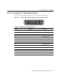
Matrix N Series N-POE Power System Installation Guide PORT 1 48V 25A MAX OUTPUT PORT 2 48V 25A MAX OUTPUT PORT 3 48V PORT 4 25A MAX OUTPUT 48V 48V PS 1 PS 3 ON BKR 6 25A ON ON OFF OFF BKR 5 25A ON BKR 3 25A ON OFF OFF BKR 2 25A BKR 7 25A PS 2 PS 4 ON OFF OFF BKR 4 25A 9033952-04 25A MAX OUTPUT ON OFF BKR 1 25A PORT 5 25A MAX OUTPUT PORT 6 48V 25A MAX OUTPUT PORT 7 48V 25A MAX OUTPUT N-POE Electrical Hazard: Only qualified personnel should perform installation procedures. Riesgo Electrico: Solamente personal calificado debe realizar procedimientos de instalacion. Elektrischer Gefahrenhinweis: Installationen sollten nur durch ausgebildetes und qualifiziertes Personal vorgenommen werden. Notice Enterasys Networks reserves the right to make changes in specifications and other information contained in this document and its web site without prior notice. The reader should in all cases consult Enterasys Networks to determine whether any such changes have been made. The hardware, firmware, or software described in this document is subject to change without notice. IN NO EVENT SHALL ENTERASYS NETWORKS BE LIABLE FOR ANY INCIDENTAL, INDIRECT, SPECIAL, OR CONSEQUENTIAL DAMAGES WHATSOEVER (INCLUDING BUT NOT LIMITED TO LOST PROFITS) ARISING OUT OF OR RELATED TO THIS DOCUMENT, WEB SITE, OR THE INFORMATION CONTAINED IN THEM, EVEN IF ENTERASYS NETWORKS HAS BEEN ADVISED OF, KNEW OF, OR SHOULD HAVE KNOWN OF, THE POSSIBILITY OF SUCH DAMAGES. Enterasys Networks, Inc. 50 Minuteman Road Andover, MA 01810 © 2005 Enterasys Networks, Inc. All rights reserved. Part Number: 9033952-04 February 2005 ENTERASYS NETWORKS, ENTERASYS MATRIX, LANVIEW, MATRIX, NETSIGHT, WEBVIEW, and any logos associated therewith, are trademarks or registered trademarks of Enterasys Networks, Inc., in the United States and other countries. All other product names mentioned in this manual may be trademarks or registered trademarks of their respective companies. Documentation URL: http://www.enterasys.com/support/manuals Documentacion URL: http://www.enterasys.com/support/manuals Dokumentation http://www.enterasys.com/support/manuals i Regulatory Compliance Information Federal Communications Commission (FCC) Notice This device complies with Part 15 of the FCC rules. Operation is subject to the following two conditions: (1) this device may not cause harmful interference, and (2) this device must accept any interference received, including interference that may cause undesired operation. NOTE: This equipment has been tested and found to comply with the limits for a class A digital device, pursuant to Part 15 of the FCC rules. These limits are designed to provide reasonable protection against harmful interference when the equipment is operated in a commercial environment. This equipment uses, generates, and can radiate radio frequency energy and if not installed in accordance with the operator’s manual, may cause harmful interference to radio communications. Operation of this equipment in a residential area is likely to cause interference in which case the user will be required to correct the interference at his own expense. WARNING: Changes or modifications made to this device which are not expressly approved by the party responsible for compliance could void the user’s authority to operate the equipment. Industry Canada Notice This digital apparatus does not exceed the class A limits for radio noise emissions from digital apparatus set out in the Radio Interference Regulations of the Canadian Department of Communications. Le présent appareil numérique n’émet pas de bruits radioélectriques dépassant les limites applicables aux appareils numériques de la class A prescrites dans le Règlement sur le brouillage radioélectrique édicté par le ministère des Communications du Canada. Class A ITE Notice WARNING: This is a Class A product. In a domestic environment this product may cause radio interference in which case the user may be required to take adequate measures. Clase A. Aviso de ITE ADVERTENCIA: Este es un producto de Clase A. En un ambiente doméstico este producto puede causar interferencia de radio en cuyo caso puede ser requerido tomar medidas adecuadas. Klasse A ITE Anmerkung ACHTUNG: Dieses Produkt zählt zur Klasse A ( Industriebereich ). In Wohnbereichen kann es hierdurch zu Funkstörungen kommen, daher sollten angemessene Vorkehrungen zum Schutz getroffen werden. Product Safety This product complies with the following: UL 60950, CSA C22.2 No. 60950, 73/23/EEC, EN 60950, IEC 60950. Seguridad del Producto El producto de Enterasys cumple con lo siguiente: UL 60950, CSA C22.2 No. 60950, 73/23/EEC, EN 60950, IEC 60950. Produktsicherheit Dieses Produkt entspricht den folgenden Richtlinien: UL 60950, CSA C22.2 No. 60950, 73/23/EEC, EN 60950, IEC 60950. ii Electromagnetic Compatibility (EMC) This product complies with the following: 47 CFR Parts 2 and 15, CSA C108.8, 89/336/EEC, EN 55022, EN 61000-3-2, EN 61000-3-3, EN 55024, AS/NZS CISPR 22, VCCI V-3. Compatibilidad Electromágnetica (EMC) Este producto de Enterasys cumple con lo siguiente: 47 CFR Partes 2 y 15, CSA C108.8, 89/336/EEC, EN 55022, EN 55024, EN 61000-3-2, EN 61000-3-3, AS/NZS CISPR 22, VCCI V-3. Elektro- magnetische Kompatibilität ( EMC ) Dieses Produkt entspricht den folgenden Richtlinien: 47 CFR Parts 2 and 15, CSA C108.8, 89/336/EEC, EN 55022, EN 61000-3-2, EN 61000-3-3, EN 55024, AS/NZS CISPR 22, VCCI V-3. VCCI Notice This is a class A product based on the standard of the Voluntary Control Council for Interference by Information Technology Equipment (VCCI). If this equipment is used in a domestic environment, radio disturbance may arise. When such trouble occurs, the user may be required to take corrective actions. BSMI EMC Statement — Taiwan This is a class A product. In a domestic environment this product may cause radio interference in which case the user may be required to take adequate measures. iii Declaration of Conformity Application of Council Directive(s): Manufacturer’s Name: Manufacturer’s Address: European Representative Address: Conformance to Directive(s)/Product Standards: Equipment Type/Environment: 89/336/EEC 73/23/EEC Enterasys Networks, Inc. 50 Minuteman Road Andover, MA 01810 USA Enterasys Networks, Ltd. Nexus House, Newbury Business Park London Road, Newbury Berkshire RG14 2PZ, England EC Directive 89/336/EEC EN 55022 EN 61000-3-2 EN 61000-3-3 EN 55024 EC Directive 73/23/EEC EN 60950 Networking Equipment, for use in a Commercial or Light Industrial Environment. Enterasys Networks, Inc. declares that the equipment packaged with this notice conforms to the above directives. iv Enterasys Networks, Inc. Firmware License Agreement BEFORE OPENING OR UTILIZING THE ENCLOSED PRODUCT, CAREFULLY READ THIS LICENSE AGREEMENT. This document is an agreement (“Agreement”) between the end user (“You”) and Enterasys Networks, Inc. on behalf of itself and its Affiliates (as hereinafter defined) (“Enterasys”) that sets forth Your rights and obligations with respect to the Enterasys software program/firmware installed on the Enterasys product (including any accompanying documentation, hardware or media) (“Program”) in the package and prevails over any additional, conflicting or inconsistent terms and conditions appearing on any purchase order or other document submitted by You. “Affiliate” means any person, partnership, corporation, limited liability company, or other form of enterprise that directly or indirectly through one or more intermediaries, controls, or is controlled by, or is under common control with the party specified. This Agreement constitutes the entire understanding between the parties, and supersedes all prior discussions, representations, understandings or agreements, whether oral or in writing, between the parties with respect to the subject matter of this Agreement. The Program may be contained in firmware, chips or other media. BY INSTALLING OR OTHERWISE USING THE PROGRAM, YOU REPRESENT THAT YOU ARE AUTHORIZED TO ACCEPT THESE TERMS ON BEHALF OF THE END USER (IF THE END USER IS AN ENTITY ON WHOSE BEHALF YOU ARE AUTHORIZED TO ACT, “YOU” AND “YOUR” SHALL BE DEEMED TO REFER TO SUCH ENTITY) AND THAT YOU AGREE THAT YOU ARE BOUND BY THE TERMS OF THIS AGREEMENT, WHICH INCLUDES, AMONG OTHER PROVISIONS, THE LICENSE, THE DISCLAIMER OF WARRANTY AND THE LIMITATION OF LIABILITY. IF YOU DO NOT AGREE TO THE TERMS OF THIS AGREEMENT OR ARE NOT AUTHORIZED TO ENTER INTO THIS AGREEMENT, ENTERASYS IS UNWILLING TO LICENSE THE PROGRAM TO YOU AND YOU AGREE TO RETURN THE UNOPENED PRODUCT TO ENTERASYS OR YOUR DEALER, IF ANY, WITHIN TEN (10) DAYS FOLLOWING THE DATE OF RECEIPT FOR A FULL REFUND. IF YOU HAVE ANY QUESTIONS ABOUT THIS AGREEMENT, CONTACT ENTERASYS NETWORKS, LEGAL DEPARTMENT AT (978) 684-1000. You and Enterasys agree as follows: 1. LICENSE. You have the non-exclusive and non-transferable right to use only the one (1) copy of the Program provided in this package subject to the terms and conditions of this Agreement. 2. RESTRICTIONS. Except as otherwise authorized in writing by Enterasys, You may not, nor may You permit any third party to: (i) Reverse engineer, decompile, disassemble or modify the Program, in whole or in part, including for reasons of error correction or interoperability, except to the extent expressly permitted by applicable law and to the extent the parties shall not be permitted by that applicable law, such rights are expressly excluded. Information necessary to achieve interoperability or correct errors is available from Enterasys upon request and upon payment of Enterasys’ applicable fee. (ii) Incorporate the Program, in whole or in part, in any other product or create derivative works based on the Program, in whole or in part. (iii) Publish, disclose, copy, reproduce or transmit the Program, in whole or in part. (iv) Assign, sell, license, sublicense, rent, lease, encumber by way of security interest, pledge or otherwise transfer the Program, in whole or in part. (v) Remove any copyright, trademark, proprietary rights, disclaimer or warning notice included on or embedded in any part of the Program. v 3. APPLICABLE LAW. This Agreement shall be interpreted and governed under the laws and in the state and federal courts of the Commonwealth of Massachusetts without regard to its conflicts of laws provisions. You accept the personal jurisdiction and venue of the Commonwealth of Massachusetts courts. None of the 1980 United Nations Convention on Contracts for the International Sale of Goods, the United Nations Convention on the Limitation Period in the International Sale of Goods, and the Uniform Computer Information Transactions Act shall apply to this Agreement. 4. EXPORT RESTRICTIONS. You understand that Enterasys and its Affiliates are subject to regulation by agencies of the U.S. Government, including the U.S. Department of Commerce, which prohibit export or diversion of certain technical products to certain countries, unless a license to export the Program is obtained from the U.S. Government or an exception from obtaining such license may be relied upon by the exporting party. If the Program is exported from the United States pursuant to the License Exception CIV under the U.S. Export Administration Regulations, You agree that You are a civil end user of the Program and agree that You will use the Program for civil end uses only and not for military purposes. If the Program is exported from the United States pursuant to the License Exception TSR under the U.S. Export Administration Regulations, in addition to the restriction on transfer set forth in Sections 1 or 2 of this Agreement, You agree not to (i) reexport or release the Program, the source code for the Program or technology to a national of a country in Country Groups D:1 or E:2 (Albania, Armenia, Azerbaijan, Belarus, Bulgaria, Cambodia, Cuba, Estonia, Georgia, Iraq, Kazakhstan, Kyrgyzstan, Laos, Latvia, Libya, Lithuania, Moldova, North Korea, the People’s Republic of China, Romania, Russia, Rwanda, Tajikistan, Turkmenistan, Ukraine, Uzbekistan, Vietnam, or such other countries as may be designated by the United States Government), (ii) export to Country Groups D:1 or E:2 (as defined herein) the direct product of the Program or the technology, if such foreign produced direct product is subject to national security controls as identified on the U.S. Commerce Control List, or (iii) if the direct product of the technology is a complete plant or any major component of a plant, export to Country Groups D:1 or E:2 the direct product of the plant or a major component thereof, if such foreign produced direct product is subject to national security controls as identified on the U.S. Commerce Control List or is subject to State Department controls under the U.S. Munitions List. 5. UNITED STATES GOVERNMENT RESTRICTED RIGHTS. The enclosed Program (i) was developed solely at private expense; (ii) contains “restricted computer software” submitted with restricted rights in accordance with section 52.227-19 (a) through (d) of the Commercial Computer Software-Restricted Rights Clause and its successors, and (iii) in all respects is proprietary data belonging to Enterasys and/or its suppliers. For Department of Defense units, the Program is considered commercial computer software in accordance with DFARS section 227.7202-3 and its successors, and use, duplication, or disclosure by the Government is subject to restrictions set forth herein. 6. DISCLAIMER OF WARRANTY. EXCEPT FOR THOSE WARRANTIES EXPRESSLY PROVIDED TO YOU IN WRITING BY Enterasys, Enterasys DISCLAIMS ALL WARRANTIES, EITHER EXPRESS OR IMPLIED, INCLUDING BUT NOT LIMITED TO IMPLIED WARRANTIES OF MERCHANTABILITY, SATISFACTORY QUALITY, FITNESS FOR A PARTICULAR PURPOSE, TITLE AND NON- INFRINGEMENT WITH RESPECT TO THE PROGRAM. IF IMPLIED WARRANTIES MAY NOT BE DISCLAIMED BY APPLICABLE LAW, THEN ANY IMPLIED WARRANTIES ARE LIMITED IN DURATION TO THIRTY (30) DAYS AFTER DELIVERY OF THE PROGRAM TO YOU. 7. LIMITATION OF LIABILITY. IN NO EVENT SHALL ENTERASYS OR ITS SUPPLIERS BE LIABLE FOR ANY DAMAGES WHATSOEVER (INCLUDING, WITHOUT LIMITATION, DAMAGES FOR LOSS OF BUSINESS, PROFITS, BUSINESS INTERRUPTION, LOSS OF BUSINESS INFORMATION, SPECIAL, INCIDENTAL, CONSEQUENTIAL, OR RELIANCE DAMAGES, OR OTHER LOSS) ARISING OUT OF THE USE OR INABILITY TO USE THE PROGRAM, EVEN IF ENTERASYS HAS BEEN ADVISED OF THE POSSIBILITY OF SUCH DAMAGES. THIS FOREGOING LIMITATION SHALL APPLY REGARDLESS OF THE CAUSE OF ACTION UNDER WHICH DAMAGES ARE SOUGHT. THE CUMULATIVE LIABILITY OF ENTERASYS TO YOU FOR ALL CLAIMS RELATING TO THE PROGRAM, IN CONTRACT, TORT OR OTHERWISE, SHALL NOT EXCEED THE TOTAL AMOUNT OF FEES PAID TO ENTERASYS BY YOU FOR THE RIGHTS GRANTED HEREIN. vi 8. AUDIT RIGHTS. You hereby acknowledge that the intellectual property rights associated with the Program are of critical value to Enterasys and, accordingly, You hereby agree to maintain complete books, records and accounts showing (i) license fees due and paid, and (ii) the use, copying and deployment of the Program. You also grant to Enterasys and its authorized representatives, upon reasonable notice, the right to audit and examine during Your normal business hours, Your books, records, accounts and hardware devices upon which the Program may be deployed to verify compliance with this Agreement, including the verification of the license fees due and paid Enterasys and the use, copying and deployment of the Program. Enterasys’ right of examination shall be exercised reasonably, in good faith and in a manner calculated to not unreasonably interfere with Your business. In the event such audit discovers non-compliance with this Agreement, including copies of the Program made, used or deployed in breach of this Agreement, You shall promptly pay to Enterasys the appropriate license fees. Enterasys reserves the right, to be exercised in its sole discretion and without prior notice, to terminate this license, effective immediately, for failure to comply with this Agreement. Upon any such termination, You shall immediately cease all use of the Program and shall return to Enterasys the Program and all copies of the Program. 9. OWNERSHIP. This is a license agreement and not an agreement for sale. You acknowledge and agree that the Program constitutes trade secrets and/or copyrighted material of Enterasys and/or its suppliers. You agree to implement reasonable security measures to protect such trade secrets and copyrighted material. All right, title and interest in and to the Program shall remain with Enterasys and/or its suppliers. All rights not specifically granted to You shall be reserved to Enterasys. 10. ENFORCEMENT. You acknowledge and agree that any breach of Sections 2, 4, or 9 of this Agreement by You may cause Enterasys irreparable damage for which recovery of money damages would be inadequate, and that Enterasys may be entitled to seek timely injunctive relief to protect Enterasys’ rights under this Agreement in addition to any and all remedies available at law. 11. ASSIGNMENT. You may not assign, transfer or sublicense this Agreement or any of Your rights or obligations under this Agreement, except that You may assign this Agreement to any person or entity which acquires substantially all of Your stock or assets. Enterasys may assign this Agreement in its sole discretion. This Agreement shall be binding upon and inure to the benefit of the parties, their legal representatives, permitted transferees, successors and assigns as permitted by this Agreement. Any attempted assignment, transfer or sublicense in violation of the terms of this Agreement shall be void and a breach of this Agreement. 12. WAIVER. A waiver by Enterasys of a breach of any of the terms and conditions of this Agreement must be in writing and will not be construed as a waiver of any subsequent breach of such term or condition. Enterasys’ failure to enforce a term upon Your breach of such term shall not be construed as a waiver of Your breach or prevent enforcement on any other occasion. 13. SEVERABILITY. In the event any provision of this Agreement is found to be invalid, illegal or unenforceable, the validity, legality and enforceability of any of the remaining provisions shall not in any way be affected or impaired thereby, and that provision shall be reformed, construed and enforced to the maximum extent permissible. Any such invalidity, illegality or unenforceability in any jurisdiction shall not invalidate or render illegal or unenforceable such provision in any other jurisdiction. 14. TERMINATION. Enterasys may terminate this Agreement immediately upon Your breach of any of the terms and conditions of this Agreement. Upon any such termination, You shall immediately cease all use of the Program and shall return to Enterasys the Program and all copies of the Program. vii viii Contents About this Guide Using This Guide ................................................................................................................................. xi Who Should Use This Guide ................................................................................................................ xi How to Use This Guide ....................................................................................................................... xii Using the Matrix N Series Manual Set ................................................................................................ xii Conventions Used in This Guide ........................................................................................................xiii Chapter 1: Introduction N-POE Power System (NPS) Overview .............................................................................................1-2 N-POE Chassis ..................................................................................................................................1-3 Optional N-POE Power Supply Module (N-POE PSM) ......................................................................1-3 N-POE PSM Status LEDs ..................................................................................................................1-4 Powered Devices (PDs) .....................................................................................................................1-4 Power Classifications and Deployment ..............................................................................................1-4 Getting Help .......................................................................................................................................1-7 Chapter 2: Installation Required Tools ...................................................................................................................................2-2 Unpacking Chassis and Power Supply Module(s) .............................................................................2-2 Installing N-POE PSMs ......................................................................................................................2-3 Replacing an N-POE PSM ..........................................................................................................2-6 Installing N-POE Chassis into a Rack ................................................................................................2-7 Guidelines for Rackmount Installation .........................................................................................2-7 Rack Mounting the Chassis .........................................................................................................2-8 Connecting the DFE-POE-CBL-2M Cable and AC Power Cord ........................................................2-9 DFE-POE-CBL-2M Cable ............................................................................................................2-9 AC Power Cord ..........................................................................................................................2-12 Appendix A: Specifications N-POE Chassis Specifications .......................................................................................................... A-1 Port 1 through Port 7 Pinout Description .......................................................................................... A-3 N-POE-1200 W Specifications .......................................................................................................... A-4 AC Power Cord ................................................................................................................................. A-5 DFE-POE-CBL-2M Cable ................................................................................................................. A-5 Compliance Standards ...................................................................................................................... A-5 ix Figures 1-1 1-2 1-3 2-1 2-2 2-3 2-4 2-5 2-6 2-7 A-1 Matrix N-POE Chassis (front and rear view) ..........................................................................1-2 N-POE PSM Front Panel .......................................................................................................1-3 Example of a Simple N-POE Power Configuration ................................................................1-5 Removing a Chassis Bay Cover ............................................................................................2-5 Installing the N-POE PSM......................................................................................................2-5 Fastening the N-POE Chassis to the Rack ............................................................................2-8 Circuit Breaker Operation.......................................................................................................2-9 DFE-POE-CBL-2M Cable Connections ...............................................................................2-11 AC Power Connections ........................................................................................................2-13 Matrix N-POE Chassis Status LEDs and Circuit Breakers...................................................2-14 48 Vdc D-Sub Female Front-Panel Port Connector Pinouts................................................. A-3 Tables 1-1 2-1 2-2 2-3 2-4 A-1 A-2 A-3 A-4 A-5 x DTE PoE Power Classifications .............................................................................................1-5 Contents of N-POE Chassis Carton.......................................................................................2-2 Contents of an Optional N-POE PSM Carton ........................................................................2-2 Power Distribution According to Number of Installed Power Supplies...................................2-4 N-POE PSM Status LED Indications and Recommended Actions ......................................2-15 N-POE Chassis Specifications.............................................................................................. A-1 48 Vdc D-Sub Pinout Description.......................................................................................... A-3 N-POE-1200 W Specifications .............................................................................................. A-4 AC Power Cord Specifications .............................................................................................. A-5 Compliance Standards.......................................................................................................... A-5 About this Guide This guide provides an overview, installation and troubleshooting instructions, and specifications for the Enterasys Matrix N-POE power system, which can provide up to seven 48 Vdc power sources to DFE series PoE-compliant switch modules in an N3 or N7 network system chassis. Using This Guide Read through this guide completely to familiarize yourself with its contents and gain an understanding of the features and capabilities of the N-POE power system (NPS) components. A general working knowledge of data communications networks is helpful when setting up an NPS. Who Should Use This Guide This guide is intended for a network administrator responsible for installing and setting up the switch. Electrical Hazard: Only qualified personnel should install or service this unit. Riesgo Eléctrico: Nada mas personal capacitado debe de instalar o darle servicio a esta unida. Elektrischer Gefahrenhinweis: Installationen oder Servicearbeiten sollten nur durch ausgebildetes und qualifiziertes Personal vorgenommen werden. Matrix N Series N-POE Power Supply System Installation Guide xi How to Use This Guide How to Use This Guide For... Refer to... An overview of the features and capabilities of the NPS, introduction to powered devices (PDs) and Power Classification, and power system deployment. This chapter also provides instructions for obtaining help from Enterasys Networks, if needed. Chapter 1, Introduction Instructions to install an NPS into a standard 19-inch rack. This includes installing the N-POE Chassis, one to four N-POE PSMs, interconnecting DFE-POE-CBL-2M 48 Vdc Cables, and AC power cords. Troubleshooting is also covered in this chapter. Chapter 2, Installation Specifications, environmental requirements, and physical properties of the N-POE Chassis, N-POE PSM, N-POE-1200W power supply, DFE-POE-CBL-2M 48 Vdc Cable, 48 Vdc Port D-sub pin-out description, and Compliance Standards. Appendix A, Specifications Using the Matrix N Series Manual Set The Matrix N-POE Series of switches support PoE-compliant 48 Vdc/data connections through the same cable, to remote powered devices (PDs) such as telephones, fax machines and other devices that meet PoE standards. The N-POE Series switch manuals explain how to install the switch, connect the 48 Vdc/data cables to the external powered devices (PDs), and configure the switch using command line interface commands described in the Matrix DFE Series Configuraton Guide. Each manual is written for qualified personnel who are responsible for installing the switch device and also have a general working knowledge of data communication networks and their physical layer components. The manuals can be accessed on the World Wide Web, using the following URL: Documentation URL: http://www.enterasys.com/support/manuals Documentacion URL: http://www.enterasys.com/support/manuals Dokumentation http://www.enterasys.com/support/manuals xii About this Guide Conventions Used in This Guide Conventions Used in This Guide The following conventions are used in this guide: Note: Calls the reader’s attention to any item of information that may be of special importance. Caution: Contains information essential to avoid damage to the equipment. Precaución: Contiene información esencial para prevenir dañar el equipo. Achtung: Verweißt auf wichtige Informationen zum Schutz gegen Beschädigungen. Electrical Hazard: Warns against an action that could result in personal injury or death due to an electrical hazard. Riesgo Electrico: Advierte contra una acción que pudiera resultar en lesión corporal o la muerte debido a un riesgo eléctrico. Elektrischer Gefahrenhinweis: Warnung vor sämtlichen Handlungen, die zu Verletzung von Personen oder Todesfällen – hervorgerufen durch elektrische Spannung – führen können! Warning: Warns against an action that could result in personal injury or death. Advertencia: Advierte contra una acción que pudiera resultar en lesión corporal o la muerte. Warnhinweis: Warnung vor Handlungen, die zu Verletzung von Personen oder gar Todesfällen führen können! Matrix N Series N-POE Power Supply System Installation Guide xiii Conventions Used in This Guide xiv About this Guide 1 Introduction This chapter provides a functional overview of the N-POE system, which includes the following: For information about... Refer to page... N-POE Power System (NPS) Overview 1-2 N-POE Chassis 1-3 Optional N-POE Power Supply Module (N-POE PSM) 1-3 N-POE PSM Status LEDs 1-4 Powered Devices (PDs) 1-4 Power Classifications and Deployment 1-4 Getting Help 1-7 Note: In this document, the following terms are used: • NPS refers to the complete N-POE power system. • N-POE Chassis refers to the N-POE Chassis only. • N-POE PSM refers to the N-POE-1200 W DC power supply module. • PoE refers to the Power over Ethernet (802.3af) compliance standard. • PoE switch module refers to a DFE Series PoE-compliant switch module. • PD refers to powered devices, which can operate using 48 Vdc received through new or existing Ethernet data cable. Matrix N Series N-POE Power System Installation Guide 1-1 N-POE Power System (NPS) Overview N-POE Power System (NPS) Overview The N-POE Chassis can house up to four N-POE PSMs to provide an N-POE Power System to meet your needs and can consist of the following components: • One N-POE Chassis • One to four optional N-POE PSMs. Each are shipped with their own AC power cord. • One to seven optional DFE-POE-CBL-2M Cables The NPS enables you to expand the capability of the Matrix N3 and Matrix N7 chassis to operate Enterasys PoE switch modules, which support connections to powered devices (PDs). This is accomplished by providing the 48 Vdc necessary for the PoE switch modules to support 48 Vdc/data connections to powered devices (PDs). The N-POE Chassis and N-POE PSM are shown in Figure 1-1 and Figure 1-2, respectively. Figure 1-1 Matrix N-POE Chassis (front and rear view) Á PORT 1 48V 25A MAX OUTPUT PORT 2 48V PORT 4 25A MAX OUTPUT 48V PORT 5 25A MAX OUTPUT 48V 25A MAX OUTPUT PORT 6 48V PORT 7 25A MAX OUTPUT 48V PS 1 BKR 5 25A ON ON BKR 6 25A ON ON OFF OFF ON BKR 3 25A N-POE  PS 3 BKR 2 25A 25A MAX OUTPUT ON BKR 1 25A OFF OFF à PORT 3 48V OFF À 25A MAX OUTPUT BKR 7 25A PS 2 PS 4 ON OFF OFF BKR 4 25A Ä CAUTION: THIS UNIT MAY HAVE MORE THAN ONE POWER SUPPLY CORD. DISCONNECT FOUR (4) POWER SUPPLY CORDS BEFORE SERVICING TO AVOID ELECTRIC SHOCK. VORSICHT: DIESES GERÄT HAT MEHR ALS EINEN NETZANSSCHLUß. TRENNEN SIE VOR WARTUNGSARBEITEN DIE 4 NETZANSCHLÜSSE VOM NETZ, UM ELEKTRISCHE SCHLÄGE ZU VERMEIDEN. AC INLET 3 Å 100 - 125V ~ 15A 200 - 240V ~ 8A 50/60 Hz 100 - 125V ~ 15A 200 - 240V ~ 8A 50/60 Hz AC INLET 4 AC INLET 2 100 - 125V ~ 15A 200 - 240V ~ 8A 50/60 Hz 1 2 3 4 1-2 Introduction AC INLET 1 100 - 125V ~ 15A 200 - 240V ~ 8A 50/60 Hz S/N: Æ Ç Æ N-POE Chassis (front view) Seven D-Sub 48 Vdc output ports (Ports 1–7) Power supply bay cover Power supply bay PS1(shown with an optional N-POE PSM installed) 5 6 7 8 25 A circuit breakers for each N-POE PSM N-POE Chassis (rear view) Air discharge vents (2) Four AC power input connectors N-POE Chassis Figure 1-2 N-POE PSM Front Panel À Á à 1 2 Intake cooling fan Green DC power LED (DC within specification)  3 4 Handle Red AC power LED (AC out of specification) N-POE Chassis The N-POE Chassis features include the following: • Supports up to four N-POE PSMs in an N+1 configuration (if two or more N-POE PSMs are installed and one fails, power is provided by the remaining N-POE PSMs). • Easy front panel access to seven D-Sub 48 Vdc, 25 A connectors that can provide power for up to seven PoE switch modules residing in an N3 or N7 chassis. • Easy access to circuit breaker/reset switch for each 48 Vdc, 25 A output. • Separate AC power inlet connectors for each N-POE PSM installed. • Installs in a standard 19-inch rack to provide maximum wiring closet port density. Optional N-POE Power Supply Module (N-POE PSM) The N-POE PSM features include the following: • Hot swappable capability as long as the total power needed does not exceed the power output capability of the remaining N-POE PSMs in the N-POE Chassis. • Provides a maximum power output of 1200 W to PoE switch modules. The maximum number of PDs supported by each PoE switch module is dependent on the PD power consumption as indicated by their Power Classifications. For details about Power Classification, refer to “Powered Devices (PDs)” on page 1-4. Matrix N Series N-POE Power System Installation Guide 1-3 N-POE PSM Status LEDs • Provides power redundancy when two N-POE PSMs are installed in the N-POE Chassis and there is no more than a 1200-Watt demand by the connected DFE series switch module to support PDs. So if one N-POE PSM fails or is removed from the chassis, the other N-POE PSM can support the total load. • Provides continuous power sharing by all N-POE PSMs when two or more are installed in the N-POE Chassis. Up to four N-POE PSMs can be installed in the N-POE Chassis to provide up to 4800 Watts of power. N-POE PSM Status LEDs There are two status LEDs (AC power LED and DC power LED) on each N-POE PSM. The AC power LED is green when the N-POE PSM AC power input is within specifications and turns off when it is not. The DC power LED is green when the N-POE PSM 48 Vdc output is within specifications and turns off when it is not. Powered Devices (PDs) PDs are devices that receive their operating 48 Vdc power through a new or existing Ethernet cable from a switch or other device that can provide a PoE-compliant port connection. This enables the PD to operate in a location without local power. For example: • Devices such as PoE-compliant remote EXIT signs and Personal Data Assistants (PDAs), • Devices that support Voice over IP such as PoE-compliant digital telephones, • Devices that support Wireless Application Protocol (WAP) such as security cameras, laptop PCs, and many more devices. Each device is rated according to a PoE Power Classification assigned by the manufacturer. If you know the classification of the PDs connected to your system, you can approximate the total amount of power needed to operate the PDs and plan accordingly. Power Classifications and Deployment The number of N-POE PSMs needed to power the PoE-compliant PDs is dependent on their Power Classifications. Each N-POE PSM can supply up to 1200 Watts of power. You can determine the number of power supplies needed by referring to Table 1-1 and adding up the maximum power requirement according to the Power Classification rating (1 through 3) of each PD. Keep in mind that each classification represents a range of power, so your maximum calculation represents a worst-case power consumption, so the actual power consumption could be less. 1-4 Introduction Power Classifications and Deployment Table 1-1 DTE PoE Power Classifications DTE Maximum Power Range Usage Class Usage 0 Default 0.44 to 12.95 Watts 1 Optional 0.44 to 3.84 Watts 2 Optional 3.84 to 6.49 Watts 3 Optional 6.49 to 12.95 Watts 4 Not Allowed Reserved for Future Use Figure 1-3 shows an example of a simple configuration with one 48 Vdc output port from an N-POE Chassis connected to a PoE switch module (such as Enterasys Networks’ 7H4385-49). The N-POE Chassis connection provides 48 Vdc and its power supply status information (indicates if the power supply is okay) to the PoE switch module. Figure 1-3 Example of a Simple N-POE Power Configuration À FAST ENET 7H4385-49 OFFLINE/ RESET COM 1X 2X MGMT CPU POE GROUP SELECT GROUP 1 2 2 3 3 4 1 1 G R O U P 4 È Á 5 6 7 8 9 11X 12 X 13X 14X 10 11 12 G R O U P  2 23X 24X 25X 26X à G R O U P 3 35X 36X 37X 38X Ä G R O U P 4 47X 48X DFE PORT 1 48V 25A MAX OUTPUT PORT 2 48V Å Æ Ç 25A MAX OUTPUT PORT 3 48V PORT 4 25A MAX OUTPUT 48V 48V PS 1 ON BKR 6 25A ON ON OFF OFF BKR 5 25A ON BKR 3 25A ON OFF OFF BKR 2 25A 25A MAX OUTPUT PORT 7 48V 25A MAX OUTPUT N-POE BKR 7 25A PS 4 ON 6 7 8 9 OFF OFF BKR 4 25A DTE, non-PoE compliant PD, no Class rating PD, Class 2 PD, Class 2 PD, Class 3 PORT 6 48V PS 3 PS 2 1 2 3 4 5 25A MAX OUTPUT ON OFF BKR 1 25A PORT 5 25A MAX OUTPUT PD, Class 4 NPS 48 Vdc/Status cable (DFE-POE-CBL-2M) PoE-compliant switch module Matrix N Series N-POE Power System Installation Guide 1-5 Power Classifications and Deployment The PoE switch module manages the 48 Vdc output to the six PDs. In this example, six of the PoE module 48 Vdc/data ports are to PDs with the following Class ratings: • One does not support PoE (no power) • One has no Class rating (Defaults to Class 0, 12.95 Watts maximum) • Two are Class 2 (6.49 Watts maximum x 2 = 12.98 Watts total) • One is Class 3 (12.95 Watts maximum) • One is Class 4 (defaults to 12.95 Watts maximum) The maximum power needed from the N-POE Chassis is 51.83 Watts. In this example, only one N-POE PSM would be needed in the N-POE Chassis. However, as an option a second N-POE PSM can be installed for redundancy. As long as N-POE PSMs are sharing a load of under 1200 Watts, one N-POE PSM can handle the load if the other fails or is removed from the N-POE Chassis. 1-6 Introduction Getting Help Getting Help For additional support related to the devices or this document, contact Enterasys Networks using one of the following methods: World Wide Web http://www.enterasys.com/support Phone 603-332-9400 1-800-872-8440 (toll-free in U.S. and Canada) For the Enterasys Networks Support toll-free number in your country: http://www.enterasys.com/support/gtac-all.html Internet mail [email protected] To expedite your message, please type [switching] in the subject line. To send comments or suggestions concerning this document to the Technical Writing Department: [email protected] To expedite your message, please include the document Part Number in the email message. Before contacting Enterasys Networks for technical support, have the following information ready: • Your Enterasys Networks service contract number • A description of the failure • A description of any action(s) already taken to resolve the problem (e.g., changing mode switches, rebooting the unit, etc.) • The serial and revision numbers of all involved Enterasys Networks products in the network • A description of your network environment (layout, cable type, etc.) • Network load and frame size at the time of trouble (if known) • The device history (i.e., have you returned the device before, is this a recurring problem, etc.) • Any previous Return Material Authorization (RMA) numbers Matrix N Series N-POE Power System Installation Guide 1-7 Getting Help 1-8 Introduction 2 Installation Electrical Hazard: Only qualified personnel should perform installation procedures. Riesgo Electrico: Solamente personal calificado debe realizar procedimientos de instalacion. Elektrischer Gefahrenhinweis: Installationen sollten nur durch ausgebildetes und qualifiziertes Personal vorgenommen werden. This chapter provides the installation instructions to install all the components of an NPS. To correctly install an NPS, follow the order of information listed below. For information about... Refer to page... Required Tools 2-2 Unpacking Chassis and Power Supply Module(s) 2-2 Installing N-POE PSMs 2-3 Installing N-POE Chassis into a Rack 2-7 Connecting the DFE-POE-CBL-2M Cable and AC Power Cord 2-9 Troubleshooting 2-14 Matrix N Series N-POE Power System Installation Guide 2-1 Required Tools Required Tools A Phillips screwdriver is required to install the N-POE Chassis and Allen wrench for the N-POE PSMs. Unpacking Chassis and Power Supply Module(s) To unpack the N-POE Chassis or an N-POE PSM, proceed as follows: 1. Open the box and remove the packing material protecting the devices. 2. Verify the contents of each carton and compare the contents shipped with those listed in Table 2-1 and Table 2-2. 3. Perform a visual inspection of the devices for any signs of physical damage. Contact Enterasys Networks if there are any signs of damage. Refer to “Getting Help” on page 1-7 for details. Table 2-1 Contents of N-POE Chassis Carton Item Quantity N-POE Chassis 1 Manual Accessory Kit 1 Reusable ESD Wrist Strap 1 Table 2-2 Contents of an Optional N-POE PSM Carton Item Quantity N-POE-1200 W DC Power Supply Module 1 USA, NEMA Power Cord 5-20, C19, R/A, SHLD1 1 Notice Card 1 1. If a power cord needs to be replaced, it must meet the requirements specified in “AC Power Cord” on page A-5. Note: The DFE-POE-CBL-2M Cable power cables used to make connections from the N-POE Chassis to the N-PoE switch modules must be ordered separately. 2-2 Installation Installing N-POE PSMs Installing N-POE PSMs Before installing the N-POE Chassis in a rack, refer back to “Powered Devices (PDs)” on page 1-4 to determine how many N-POE PSMs will be needed in the N-POE Chassis. One box with an N-POE PSM is shipped separately from the N-POE Chassis. Additional N-POE PSMs are ordered separately. Caution: Observe all Electrostatic Discharge (ESD) precautions when handling sensitive electronic equipment. Precaución: Al trabajar con equipos electrónicos sensibles, tome todas las precauciones de seguridad para evitar descargas de electricidad estática. The N-POE Chassis is shipped with safety covers over each of the seven front-panel 48 Vdc, 25 A Maximum Outputs (Ports 1 through 7). Do not remove a safety cover unless you plan to connect a DFE-POE-CBL-2M Cable. Ports without a cable connected must have the safety cover installed to protect against an energy hazard. Warning: The rated output of these ports is 48 Vdc, 25A. This is an energy hazard and care should be taken not to bridge the contacts of this connector. The safety cover must remain in place until the N-POE Cable is installed and connected to its corresponding module. Advertencia: La salida de estos puertos es 48 Vdc, 25A. Esto es un riesgo electrico y debe tenerse cuidado para no puentear los contactos de este conector. La tapa de seguridad debe permanecer en su lugar hasta que el cable DFE-POE-CBL-2M sea instalado y conectado a su modulo correspondiente. Warnhinweis: Es liegen 48 V/ 25A Gleichspannung/-strom an diesen Ports an, dies liegt im elektirschen Gefahrenbereich. Es muß dafür Sorge getragen werden, dass die Kontakte des Steckers nicht überbrückt werden können. Die Schutzhüllen müssen aufgesteckt bleiben, bis das DFE-POE-CBL-2M Kabel an das installierte Modul angeschlossen ist. When you receive your N-POE Chassis, the chassis bay covers are in place over both power-supply bays. The bay covers have two purposes. They provide an intake air ventilation path, prevent EMI leakage, and provide access to the two PSM slots in each chassis bay. The left bay has power-supply slots 1 and 2; the right bay, slots 3 and 4. As shown in Table 2-3, when two to four PSMs are installed, the power supplies share the load equally and provide power redundancy. If one power supply fails or is removed (hot swapped) for any reason, the other power supplies take up the load. Power redundancy remains in effect as long as the load does not exceed the power as stated in the Redundancy column. Matrix N Series N-POE Power System Installation Guide 2-3 Installing N-POE PSMs Table 2-3 Power Distribution According to Number of Installed Power Supplies Power Redundancy Supplies Hot Power Sharing Swappable 1 No No Maximum power 1200 2 Yes, if power demand is less than 1200 Watts.1 Yes The total load is shared by both power supplies. 3 Yes, if power demand is less than 2400 Watts.1 Yes The total load is shared by the three power supplies. 4 Yes, if power demand is less than 3600 Watts.1 Yes The total load is shared by the four power supplies. 1. If power requirements exceed this Wattage, power redundancy is no longer supported. Removing a power supply under this condition will cause the remaining power supplies to go into over-current protection and shut down the power system. To install the N-POE PSMs, proceed as follows: Note: To prevent EMI leakage from the N-POE Chassis, ensure that both bay covers are installed during operation. 1. Place the N-POE Chassis on a flat sturdy surface. 2. Refer to Figure 2-1. Unscrew the two captive Phillips-head cover screws to release the bay cover from the chassis bay where you plan to install an N-POE PSM. (In this procedure, the left bay is used as an example.) Remove the bay cover and set it aside for now. Caution: In the following step, do not force the power supply into place. You could damage the power supply and/or the chassis connector. Precaución: En el siguiente paso, tenga cuidado de no colocar a fuerza la fuente de poder en su sitio. Si lo hace, podría dañar tanto la fuente como el conector del chasis. 2-4 Installation 3. Refer to Figure 2-2. Align the N-POE PSM with PS1 slot inside bay 1, then slide the N-POE PSM forward until the N-POE PSM is plugged into the PS1 slot chassis connector and completely inside the bay. If significant resistance is encountered before the N-POE PSM reaches the end of its travel, remove and reinsert the power supply. 4. Fasten the N-POE PSM to the N-POE Chassis using the two captive Phillips-head screws on the N-POE PSM front panel. 5. Repeat steps 2 through 4 for each additional N-POE PSM. Installing N-POE PSMs Caution: Remember to replace any bay cover removed during the installation to prevent EMI leakage from the chassis. Precaución: No olvide volver a colocar todas las tapas de los compartimentos que haya quitado durante el proceso de instalación para reducir la interferencia electromagnética del chasis. 6. Proceed to “Installing N-POE Chassis into a Rack” on page 2-7 for the rack mount installation instructions. Figure 2-1 Removing a Chassis Bay Cover  PORT 1 48V PORT 2 25A MAX OUTPUT 48V PORT 3 25A MAX OUTPUT 48V PORT 4 25A MAX OUTPUT 48V PORT 5 25A MAX OUTPUT 48V BKR 5 25A ON ON BKR 6 25A ON ON OFF OFF ON OFF OFF BKR 3 25A BKR 7 25A PS 2 48V 25A MAX OUTPUT N-POE PS 4 ON OFF OFF BKR 4 25A À 1 Captive Screw, Phillips head (2) 2 Bay Cover Figure 2-2 PORT 7 25A MAX OUTPUT PS 3 BKR 2 25A Á 48V ON OFF BKR 1 25A PS 1 À PORT 6 25A MAX OUTPUT 3 Chassis bay (left) Installing the N-POE PSM  PORT 1 48V PORT 2 25A MAX OUTPUT 48V 25A MAX OUTPUT PORT 3 48V PORT 4 25A MAX OUTPUT 48V 48V PS 1 BKR 5 25A ON ON BKR 6 25A ON ON OFF OFF ON OFF OFF BKR 3 25A BKR 7 25A PS 2 PORT 7 48V 25A MAX OUTPUT N-POE ON OFF OFF 1 N-POE Chassis 2 N-POE PSM 25A MAX OUTPUT PS 4 BKR 4 25A à PORT 6 48V PS 3 BKR 2 25A Á 25A MAX OUTPUT ON OFF BKR 1 25A PORT 5 25A MAX OUTPUT À 3 Power supply slot PS1 4 Captive screw, Phillips head Matrix N Series N-POE Power System Installation Guide 2-5 Installing N-POE PSMs Replacing an N-POE PSM To replace an N-POE PSM in an operating N-POE Chassis, proceed as follows: Caution: Observe all Electrostatic Discharge (ESD) precautions when handling sensitive electronic equipment. If power requirements exceed this Wattage as stated in Table 2-3 on page 2-4, power redundancy is no longer supported. Removing a power supply under this condition will cause the remaining power supplies to go into over-current protection and shut down the power system. Precaución: Al trabajar con equipos electrónicos sensibles, tome todas las precauciones de seguridad para evitar descargas de electricidad estática. Si los requerimientos de la fuente de poder fueran superiores a la potencia especificada en Table 2-3 on page 2-4, tenga en cuenta que el poder alternativo ya no funcionará. Si quita la fuente de poder en esas condiciones, hará que el resto de las fuentes entren en modo de protección de exceso de corriente y el sistema se apagará. 1. Unplug the AC power cord going from the AC power oulet to the N-POE Chassis AC INLET connector associated with the N-POE PSM being removed. For example, if removing the N-POE PSM in power supply slot PS1, unplug the AC INLET 1 power cord from the AC outlet. 2. At the bay opening where the PSM module slot is located, loosen the captive Phillips-head screw securing the N-POE PSM until the N-POE PSM is released from the N-POE Chassis. 3. Pull out on the N-POE PSM front-panel handle to remove the N-POE PSM from the N-POE Chassis. 4. Repeat steps 1 through 3 for each additional N-POE PSM you plan to remove. Note: If you plan to remove and not replace an N-POE PSM immediately, reinstall the bay cover over the empty power supply slots to prevent EMI leakage from the N-POE Chassis. To install an N-POE PSM, refer to steps 1 through 3 in “Installing N-POE PSMs” on page 2-3. Perform those steps for each N-POE PSM being replaced. When those steps are completed, proceed to “Connecting the DFE-POE-CBL-2M Cable and AC Power Cord” on page 2-9. 2-6 Installation Installing N-POE Chassis into a Rack Installing N-POE Chassis into a Rack To install the N-POE Chassis in a 19-inch rack, you need four user-supplied screws to fasten the N-POE Chassis to the rack rails. After installing the N-POE PSM(s) as described back in “Installing N-POE PSMs” on page 2-3, rack mount the N-POE Chassis as follows: 1. Refer to the installation guidelines (“Guidelines for Rackmount Installation” on page 2-7). 2. Install the N-POE Chassis into the rack (“Rack Mounting the Chassis” on page 2-8). 3. Connect the DFE-POE-CBL-2M power cables (“DFE-POE-CBL-2M Cable” on page 2-9). 4. Connect the AC power cords (“AC Power Cord” on page 2-12). Guidelines for Rackmount Installation The installation site must be within reach of the network cabling and meet the requirements listed below: • Ensure that the NPS is located close enough to connect 2-meter (6.6-foot) DFE-POE-CBL-2M cables from the N-POE PSMs to the N-POE switch modules. • Ensure that you order sufficient DFE-POE-CBL-2M cables for your installation. Up to seven cables may be needed, depending on how many N-POE modules you plan to use in your system’s N3 or N7 chassis. • Need one-to-four three-pronged power receptacles capable of delivering the current and voltage specified in “N-POE-1200 W Specifications” on page A-4. Up to four AC outlets on independently-fused circuits are required and must be located within 182 centimeters (6 feet) from the site. The power cords used and type of outlet are dependent on the country. In the United States, one power cord with a NEMA 5-20P plug is provided with each N-POE PSM. • An ambient temperature of between 5°C (41°F) and 40°C (104°F) must be maintained at the installation site with fluctuations of less than 10°C (18°F) per hour. Caution: To ensure proper ventilation and prevent overheating, leave a minimum clearance space of 10.16 cm (4.0 in.) at the front and rear of the N-POE Chassis. Precaución: Para asegurar una buena ventilación y evitar que el sistema se sobrecaliente, deje un espacio mínimo de 10.16 cm (4 pulgadas.) con respecto a la parte delantera y trasera del chasis N- POE. Matrix N Series N-POE Power System Installation Guide 2-7 Installing N-POE Chassis into a Rack Warning: Before installing the chassis into a rack, ensure that the rack can support the device(s) without compromising the stability of the rack. Otherwise, personal injury and/or equipment damage may result. Advertencia: Antes de instalar el chassis en un rack, asegurarse que el rack puede soportar el(los) dispositivo(s) sin comprometer la estabilidad del mismo. De otra forma puede suceder algun tipo de daño personal o del equipo. Warnhinweis: Schützen Sie sich vor Verletzungen und Geräteschaden, überzeugen Sie sich vor der Installation des Chassis in das Rack, von dessen Stabilität. Rack Mounting the Chassis Refer to Figure 2-3 and proceed as follows to install the N-POE Chassis into a 19-inch rack: 1. Position the chassis between the vertical frame members and align the mounting holes in the chassis brackets with those in the rack frame. 2. Fasten the chassis securely to the frame using eight mounting screws (user supplied). Figure 2-3 Fastening the N-POE Chassis to the Rack PORT 1 48V 25A MAX OUTPUT PORT 2 48V 25A MAX OUTPUT PORT 3 48V PORT 4 25A MAX OUTPUT 48V PORT 5 25A MAX OUTPUT 48V PS 1 ON BKR 6 25A ON ON OFF OFF BKR 5 25A ON BKR 3 25A ON OFF OFF BKR 2 25A 48V 25A MAX OUTPUT N-POE BKR 7 25A ON OFF OFF Á À 1 Rails of 19-inch rack Installation PORT 7 25A MAX OUTPUT PS 4 BKR 4 25A 2-8 PORT 6 48V PS 3 PS 2 Á 25A MAX OUTPUT ON OFF BKR 1 25A À 2 Mounting screws (supplied by user) Connecting the DFE-POE-CBL-2M Cable and AC Power Cord Connecting the DFE-POE-CBL-2M Cable and AC Power Cord DFE-POE-CBL-2M Cable The N-POE Chassis 48-Volt Output Ports 1 through 7 are connected to Enterasys Ethernet N-POE series switch modules using DFE-POE-CBL-2M cables. In the following procedure to connect an DFE-POE-CBL-2M cable, the appropriate circuit breaker needs to be set to OFF and reset to ON. Circuit Breaker Operation To set a circuit breaker to the OFF position (Figure 2-4), use a non-metallic tool to press the OFF switch. This breaks the circuit and causes the ON rocker button to pop up. To reset the circuit breaker, press on the ON rocker switch. Figure 2-4 Circuit Breaker Operation ON OFF ON OFF À  Á 1 OFF switch breaks the circuit 2 Rocker switch pops up when OFF switch is pressed. 3 Rocker switch shown pressed in ON Connecting the DFE-POE-CBL-2M Cable To connect a DFE-POE-CBL-2M cable, refer to Figure 2-5 and proceed as follows: Caution: Before connecting any DFE-POE-CBL-2M cables, set to the OFF position those circuit breakers associated with the 48-Volt Output Ports being connected to N-POE series switch modules. For example, you would set BKR2 to OFF if connecting a cable to Port 2. Precaución: Antes de conectar los cables DFE- POE- CBL- 2M, coloque los interruptores de circuito asociados a los puertos de salida de 48 voltios conectados a la módulos de las series N-POE en la posición de OFF (apagado). Por ejemplo, deberá colocar en OFF el BKR2 si éste está conectado a un cable del Puerto 2. Matrix N Series N-POE Power System Installation Guide 2-9 Connecting the DFE-POE-CBL-2M Cable and AC Power Cord Warning: The rated output of these ports is 48 Vdc, 25A. This is an energy hazard and care should be taken not to bridge the contacts of this connector. The safety cover must remain in place until the N-POE Cable is installed and connected to its corresponding module. Advertencia: La salida de estos puertos es 48 Vdc, 25A. Esto es un riesgo electrico y debe tenerse cuidado para no puentear los contactos de este conector. La tapa de seguridad debe permanecer en su lugar hasta que el cable DFE-POE-CBL-2M sea instalado y conectado a su modulo correspondiente. Warnhinweis: Es liegen 48 V/ 25A Gleichspannung/-strom an diesen Ports an, dies liegt im elektirschen Gefahrenbereich. Es muß dafür Sorge getragen werden, dass die Kontakte des Steckers nicht überbrückt werden können. Die Schutzhüllen müssen aufgesteckt bleiben, bis das DFE-POE-CBL-2M Kabel an das installierte Modul angeschlossen ist. 2-10 Installation 1. Remove and save the two screws fastening the safety cover protecting the 48-Volt OPTIONAL POWER INPUT connector. 2. Connect one end of the DFE-POE-CBL-2M cable to the 48-Volt OPTIONAL POWER INPUT connector on the N-POE switch module. 3. Connect one end of the DFE-POE-CBL-2M cable to the appropriate 48-Volt Output Port connector on the front panel of the N-POE Chassis. 4. After connecting the cables to both devices, press the circuit breaker rocker button to ON. Connecting the DFE-POE-CBL-2M Cable and AC Power Cord Figure 2-5 DFE-POE-CBL-2M Cable Connections OFFLINE/ RESET COM 1X 2X MGMT CPU POE GROUP SELECT GROUP 1 2 2 3 3 4 1 1 G R O U P 4 5 6 7 8 9 11X 12 X 13X 14X 10 11 12 G R O U P 2 Ä 23X 24X 25X 26X G R O U P 3 35X 36X 37X 38X G R O U P 4 47X 48X à DFE  Á PORT 1 48V 25A MAX OUTPUT PORT 2 48V 25A MAX OUTPUT PORT 3 48V PORT 4 25A MAX OUTPUT 48V 48V PS 1 ON BKR 6 25A ON ON OFF OFF BKR 5 25A ON BKR 3 25A ON BKR 2 25A BKR 7 25A PS 2 25A MAX OUTPUT PORT 7 48V 25A MAX OUTPUT N-POE PS 4 ON BKR 4 25A OFF OFF 1 Safety cover and attaching hardware 2 48-Volt output port connector 3 DFE-POE-CBL-2M cable PORT 6 48V PS 3 OFF OFF À 25A MAX OUTPUT ON OFF BKR 1 25A PORT 5 25A MAX OUTPUT 4 48-Volt OPTIONAL POWER INPUT 5 N-POE switch module Matrix N Series N-POE Power System Installation Guide 2-11 Connecting the DFE-POE-CBL-2M Cable and AC Power Cord AC Power Cord AC INLET 1 through AC INLET 4 at the rear of the N-POE Chassis provide power to the N-POE PSMs in slots PS1 through PS4, respectively. An AC power cord is shipped with each N-POE PSM. To connect the AC power cord, refer to Figure 2-6 and proceed as follows: In Figure 2-6 the bay cover is showing the bay cover removed for clarity. It is not necessary to remove the bay cover to observe the LED indications, because they can be seen through the grill in the bay cover. 1. Plug the AC power cord into the appropriate AC INLET connector. In this example, an N-POE PSM is installed in N-POE Chassis slot PS1. Therefore, the AC INLET 1 connector is used. 2. Plug the other end of the AC power cord into a separately fused AC power outlet that meets the power specifications provided in Appendix A. 3. Check to see if the DC power LED is green and the AC power LED is green. Otherwise, refer to “Troubleshooting” on page 2-14 to determine the problem. 4. If two or more power supplies are being installed, repeat steps 1 through 3 for each N-POE PSM. If you need additional help, contact Enterasys Networks. Refer to “Getting Help” on page 1-7 for instructions. 2-12 Installation Connecting the DFE-POE-CBL-2M Cable and AC Power Cord Figure 2-6 AC Power Connections Ã Ä PORT 1 48V 25A MAX OUTPUT PORT 2 48V PORT 3 25A MAX OUTPUT 48V PORT 4 25A MAX OUTPUT 48V 48V 25A MAX OUTPUT PORT 6 48V PORT 7 25A MAX OUTPUT 48V 25A MAX OUTPUT N-POE ON OFF BKR 1 25A PORT 5 25A MAX OUTPUT PS 1 PS 3 ON BKR 6 25A ON ON OFF OFF BKR 5 25A ON BKR 3 25A ON OFF OFF BKR 2 25A BKR 7 25A PS 2 PS 4 ON OFF OFF BKR 4 25A Á CAUTION: THIS UNIT MAY HAVE MORE THAN ONE POWER SUPPLY CORD. DISCONNECT FOUR (4) POWER SUPPLY CORDS BEFORE SERVICING TO AVOID ELECTRIC SHOCK. VORSICHT: DIESES GERÄT HAT MEHR ALS EINEN NETZANSSCHLUß. TRENNEN SIE VOR WARTUNGSARBEITEN DIE 4 NETZANSCHLÜSSE VOM NETZ, UM ELEKTRISCHE SCHLÄGE ZU VERMEIDEN. AC INLET 3 AC INLET 1 100 - 125V ~ 15A 200 - 240V ~ 8A 50/60 Hz 100 - 125V ~ 15A 200 - 240V ~ 8A 50/60 Hz AC INLET 4 AC INLET 2 100 - 125V ~ 15A 200 - 240V ~ 8A 50/60 Hz S/N: 100 - 125V ~ 15A 200 - 240V ~ 8A 50/60 Hz À  1 AC power cord 2 AC INLET 1 power connector (rear of chassis) 3 AC power source 4 DC power LED 5 AC power LED Matrix N Series N-POE Power System Installation Guide 2-13 Troubleshooting Troubleshooting Figure 2-7 shows the chassis front and rear panel, the location of the status LEDs, and the circuit breakers (BKR 1 through BKR 7) used to protect or manually disconnect the power to the seven 48 Vdc output Ports 1 through 7. Refer to Table 2-4 for a functional description of each LED and recommended actions to solve a problem. Note: In Figure 2-7, the bay cover is removed for clarity. Figure 2-7 Matrix N-POE Chassis Status LEDs and Circuit Breakers À Á PORT 1 48V 25A MAX OUTPUT PORT 2 48V PORT 3 25A MAX OUTPUT 48V PORT 4 25A MAX OUTPUT 48V 48V PS 1 BKR 5 25A ON ON BKR 6 25A ON ON OFF OFF ON OFF OFF BKR 3 25A PORT 7 25A MAX OUTPUT 48V 25A MAX OUTPUT N-POE BKR 7 25A PS 4 ON à 1 DC power good LED (green) 2 AC power failure LED (red) 3 Circuit breaker OFF switch (use non-metallic tool to reach and depress switch to disconnect power from the associated 48 Vdc Output Port 1–7). The circuit breaker button pops up to OFF position. ON OFF ON OFF  OFF OFF BKR 4 25A Installation 48V PS 3 BKR 2 25A PS 2 2-14 PORT 6 25A MAX OUTPUT ON OFF BKR 1 25A PORT 5 25A MAX OUTPUT Ä 4 Circuit breaker button in OFF position 5 Circuit breaker button in ON position (press to ON to provide power to associated 48 Vdc Output Port 1–7) Troubleshooting Table 2-4 N-POE PSM Status LED Indications and Recommended Actions LED Color State AC power LED Green DC power LED Green Recommended Action Off - AC input power to power 1. supply is off or out of specification. Check AC power cord connection to the power supply. 2. Check AC power at the power outlet. 3. Swap power cord for a known good one. 4. Remove or replace affected N-POE PSM. 5. Contact Enterasys Networks for support. Solid - AC input to power supply is within specification. None Solid - 48 Vdc power supply output is within specification. None OFF - 48 Vdc power supply output is out of specification. 1. Remove N-POE PSM from chassis. 2. Contact Enterasys Networks for support. Matrix N Series N-POE Power System Installation Guide 2-15 Troubleshooting 2-16 Installation A Specifications This appendix provides information about the following: For information about... Refer to page... N-POE Chassis Specifications A-1 Port 1 through Port 7 Pinout Description A-3 N-POE-1200 W Specifications A-4 DFE-POE-CBL-2M Cable A-5 Compliance Standards A-5 Enterasys Networks reserves the right to change the specifications at any time without notice. N-POE Chassis Specifications Table A-1 provides the physical, power and environmental specifications for the N-POE Chassis. Table A-1 N-POE Chassis Specifications Item Specification Power Supply Slots PS 1 through PS 4 Slots for optional N-POE-1200 W dc power supply modules. Modules are hot swappable. DC Outputs 48 Vdc Port 1 through Port 7 Provides operating status and 48 Vdc to N-POE devices. Output Voltage 48.0 Vdc Output Current 25.0 A Maximum Output Power 1200 W Matrix N Series N-POE Power System Installation Guide A-1 N-POE Chassis Specifications Table A-1 N-POE Chassis Specifications (continued) Item Specification Physical Dimensions without mounting brackets 12.9 H x 44.6 W x 39.73 D (cm) 5.12 H x 17.56 W x 15.7 D (in.) Dimensions with mounting brackets 12.9 H x 48.2 W x 39.73 D (cm) 5.12 H x 18.98 W x 15.70 D (in.) Approximate Weight (Unit) 8.2 kg (18.0 lb) MTBF 1,306,387 hours Electrical AC power requirement per AC INLET connection: Input Frequency: Input Voltage Range/Max. Amp.: Four AC inputs, one for each N-POE-1200 W installed. Each input (AC INLET 1 through INLET 4) require the following power for N-POE-1200 W power supplies installed in slots PS 1 through PS 4, respectively. 50/60 Hz 100 to 125 Vac/15 A per power supply Environmental A-2 Specifications Operating Temperature 5°C to 40°C (41°F to 104°F) Storage Temperature -30°C to 73°C (-22°F to 164°F) 50/60 Hz 200 to 240 Vac/8 A per power supply Port 1 through Port 7 Pinout Description Port 1 through Port 7 Pinout Description For pin location and function, refer to Figure A-1 and Table A-2, respectively. Table A-2 A3 A2 1 48 Vdc D-Sub Female Front-Panel Port Connector Pinouts 5 Figure A-1 48 Vdc D-Sub Pinout Description Name Number Function Power A1 None PS 1 1 48 Vdc Output OK PS 1 2 + 5 Vdc PS 2 3 48 Vdc Output OK PS 2 4 + 5 Vdc PS 3 5 48 Vdc Output OK PS 3 6 + 5 Vdc PS 4 7 48 Vdc Output OK PS 4 8 + 5 Vdc Common 9 Standby R Common 10 Standby R Power A2 +48 Vdc Power A3 48 Vdc return Matrix N Series N-POE Power System Installation Guide A-3 N-POE-1200 W Specifications N-POE-1200 W Specifications The following section describes the input/output port specifications. Table A-3 N-POE-1200 W Specifications Item Specification Electrical The following are all connected internally to the N-POE Chassis: AC Input Frequency Range 47 - 63 Hz Input Voltage Range 85 - 264 Vac Output Voltage 48 Vdc with • overload and short circuit protection, and Output Current Maximum Output Power • over-voltage protection (OVP) to 67.2 Vdc. 25.0 A 1200 W Physical Dimensions 4.1 H x 12.7 W x 25.4 D (cm) 1.6 H x 5.0 W x 10.0 D (in.) Over-Temperature Protection (OTP) Protects against • excessive temperatures caused by inadequate (blocked) airflow, • fan failure, or • excessive air inlet temperature. A-4 Specifications Approximate Weight (Unit) 2.1 kg (4.6 lb) MTBF 247,000 Hours AC Power Cord AC Power Cord Any AC power cord used to connect an AC power source to the N-POE Chassis must meet the specifications listed in Table A-4. Table A-4 AC Power Cord Specifications Item Specification Cord set approval The cord set must be approved for use by the governing authority in the country of installation. Inlet Connector IEC 320 C19 power cord connector. This is for connection to an AC Inlet connector on N-POE Chassis. Plug Type As required in country of installation Wire Gauge 12 AWG with 2 mm2 wires Voltage Rating 250 Volts minimum Power Cord Construction Power cord must be constructed with molded connectors at both ends. DFE-POE-CBL-2M Cable This cable is a PoE-compliant ferrite shielded cable terminated with 13W3-male and female D-Sub connectors. This cable is currently available in a 2-meter length and must be ordered separately. This cable provides the 48 Vdc operating voltages and operating status information from each 48 Vdc 25 A outputs (PS 1 through PS 7) on the N-POE Chassis front panel to the attached N-PoE switch device. Compliance Standards The N-POE and N-POE PSM meet the safety and electromagnetic compatibility (EMC) requirements listed in Table A-5: Table A-5 Compliance Standards Compliance Standards Safety UL 60950, CSA C22.2 No. 60950, 73/23/EEC, EN 60950, IEC 60950 Electromagnetic Compatibility (EMC) (Applies to RPS system with five modules installed and working with five network devices.) 47 CFR Parts 2 and 15, CSA C108.8, 89/336/EEC, EN 55022, EN 61000-3-2, EN 61000-3-3, EN 55024, AS/NZS CISPR 22, VCCI V-3 Matrix N Series N-POE Power System Installation Guide A-5 Compliance Standards A-6 Specifications