1
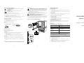
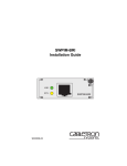
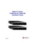
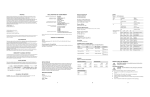
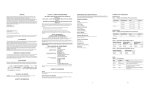
DECLARATION OF CONFORMITY NOTICE Enterasys Networks and its licensors reserve the right to make changes in specifications and other information contained in this document without prior notice. The reader should in all cases consult Enterasys Networks to determine whether any such changes have been made. The hardware, firmware, or software described in this manual is subject to change without notice. IN NO EVENT SHALL ENTERASYS NETWORKS AND ITS LICENSORS BE LIABLE FOR ANY INCIDENTAL, INDIRECT, SPECIAL, OR CONSEQUENTIAL DAMAGES WHATSOEVER (INCLUDING BUT NOT LIMITED TO LOST PROFITS) ARISING OUT OF OR RELATED TO THIS MANUAL OR THE INFORMATION CONTAINED IN IT, EVEN IF ENTERASYS NETWORKS AND ITS LICENSORS HAVE BEEN ADVISED OF, KNOWN, OR SHOULD HAVE KNOWN, THE POSSIBILITY OF SUCH DAMAGES. Enterasys Networks, Inc. 35 Industrial Way Rochester, NH 03866-5005 Application of Council Directive(s): Manufacturer’s Name: Manufacturer’s Address: European Representative Name: European Representative Address: Conformance to Directive(s)/ Product Standards: 2001 by Enterasys Networks, Inc. All Rights Reserved Printed in the United States of America Equipment Type/Environment: Order Number: 9033749 September 2001 X-Pedition and Enterasys Networks are registered trademarks of Enterasys Networks or its licensors. All other product names mentioned in this manual may be trademarks or registered trademarks of their respective companies. FCC NOTICE This device complies with Part 15 of the FCC rules. Operation is subject to the following two conditions: (1) this device may not cause harmful interference, and (2) this device must accept any interference received, including interference that may cause undesired operation. NOTE: This equipment has been tested and found to comply with the limits for a class A digital device, pursuant to Part 15 of the FCC rules. These limits are designed to provide reasonable protection against harmful interference when the equipment is operated in a commercial environment. This equipment uses, generates, and can radiate radio frequency energy and if not installed in accordance with the operator’s manual, may cause harmful interference to radio communications. Operation of this equipment in a residential area is likely to cause interference in which case the user will be required to correct the interference at his own expense. WARNING: Changes or modifications made to this device which are not expressly approved by the party responsible for compliance could void the user’s authority to operate the equipment. 89/336/EEC 73/23/EEC Enterasys Networks, Inc. 35 Industrial Way PO Box 5005 Rochester, NH 03867 Mr. Jim Sims Enterasys Networks Ltd. Nexus House, Newbury Business Park London Road, Newbury Berkshire RG14 2PZ, England ER16-SERC-04-AA CONNECTIVITY GUIDELINES The ER16-SERC-04-AA Serial card provides wide area connectivity via 4 T1/E1 ports with compression. These ports have the same switching and routing capabilities as those provided by the ethernet line cards. The ports can switch at Layer-2, Layer-3, and Layer-4, and perform both destination-based and flow-based switching. All ports are capable of bridging at Layer-2, switching IP/IPX frames at Layer-3, and switching on Layer-4 flows. Table 1 Enterasys Networks, Inc. declares that the equipment packaged with this notice conforms to the above directives. AGENCY STANDARDS Safety Meets the requirements of UL 1950, CSA C22.2 No. 950, EN 60950, IEC 950, 73/23/EEC, and EN 60825. Electromagnetic Compatibility Compliant with the requirements of FCC Part 15, CSA C108.8, EN 55022, EN 61000-3-2, EN 61000-3-3, VCCI V-3, EN 55024, 89/336/EEC, and AS/NZS 3548. Cable Type Max. Length Serial V.35, EIA-530, EIA-449, X.21 Connector 60-Pin D-Shell SPECIFICATIONS Ports 4 Serial ports with compression (up to 8MB per port) EC Directive 89/336/EEC EC Directive 73/23/EEC EN 55022 EN 55024 EN 60950 EN 60825 Networking Equipment, for use in a Commercial or Light Industrial Environment. Recommended Cable Types and Specifications LEDs Table 2 LED Indicators ASIC Type LED Condition Status -AA (Advanced ASIC) DMAC, IPP, OPP Online (2) Green The unit is operational and functioning properly. Offline (2) Amber The unit is not operational. You may remove the unit from the chassis. Tx (4) Amber A frame was transmitted. Rx (4) Amber A frame was received. Link (4) Green A valid link is established on the port. Network Interfaces 60-Pin D-shell supporting 2 serial ports per connector Physical Dimensions Size: 52.9 cm H x 2.9 W x 40.1 D (20.9 in. H x 1.15 W x 15.8 D) Weight: 2.72 kg (6.0 lbs) Power Consumption BTU/hr = 146.35 AC Volt Amps = 43.31 Temperature Operating: 32° to 104° F (0° to 40° C) Storage: -22° to 194° F (-30° to 90° C) Humidity 5% to 95% (non-condensing) INDUSTRY CANADA NOTICE This digital apparatus does not exceed the class A limits for radio noise emissions from digital apparatus set out in the Radio Interference Regulations of the Canadian Department of Communications. Le présent appareil numérique n’émet pas de bruits radioélectriques dépassant les limites applicables aux appareils numériques de la class A prescrites dans le Règlement sur le brouillage radioélectrique édicté par le ministère des Communications du Canada. VCCI NOTICE This is a class A product based on the standard of the Voluntary Control Council for Interference by Information Technology Equipment (VCCI). If this equipment is used in a domestic environment, radio disturbance may arise. When such trouble occurs, the user may be required to take corrective actions. CLASS A ITE NOTICE WARNING: This is a class A product. In a domestic environment this product may cause radio interference in which case the user may be required to take adequate measures. 1 2 INSTALLING THE MODULE CAUTION: Before performing any upgrade or installation, ensure that you are properly “grounded” to avoid electrostatic discharge. The switch must be powered off before installing or replacing any module. 1. Handling the Module CAUTION: The ER16-SERC-04-AA is easily damaged by electrostatic discharge. To prevent electrostatic damage, observe the following guidelines: Do not remove the module from its packaging until you are ready to install it. Do not touch any of the module’s pins, connectors or components. Hold the module only by its edges or front panel. Wear an anti-static wristband connected to a suitable earth ground whenever handling the module. Store or transport this module only in appropriate anti-static packaging. • • • • • TROUBLESHOOTING Instructions ELECTRICAL HAZARD: Only qualified personnel should perform installation procedures. 2. 3. If a coverplate is installed in the slot where you will install the ER16-SERC-04-AA, remove the coverplate: loosen the screws on the ejectors until the screws pop out, then open the ejectors and pull out the plate. Open the ejectors at the top and bottom of the ER16-SERC-04-AA. Align the metal backpanel with the card guides at the top and the bottom of the slot opening, as shown in Figure 1. NOTE: Make sure that the metal backpanel of the ER16-SERC-04-AA—not the circuit card—is between the card guides. Check both the upper and lower tracks. 4. 5. Slide the ER16-SERC-04-AA all the way into the slot, firmly but gently pressing to ensure that the pins on the back of the module are completely seated in the backplane. To lock the ER16-SERC-04-AA into the slot, close the ejectors. Using a flathead screwdriver, tighten the screw on each ejector. Equipment Checklist After unpacking the ER16-SERC-04-AA, check the contents of the box to be sure you received the following items: One ER16-SERC-04-AA module in anti-static bag One disposable anti-static wristband Figure 1 Install the ER16-SERC-04-AA This installation requires the following tool: Common Errors • • The ER16-SERC-04-AA is not inserted properly or seated completely in the chassis Connectors for the connected lines are not seated properly. Helpful CLI Commands for Debugging • • • • System show hardware System show version Port show port status se.x.y (where x is the chassis slot that contains the line card and y is a specific port number on the card). System show bootlog ER16-SERC-04-AA Quick Start Web Site: http://www.enterasys.com/ Getting Help For additional support related to the Common CLI syntax or this document, contact Enterasys Networks using one of the following methods: Flathead screwdriver Rotate ejector to lock in place Preliminary Setup Firmware Image Requirements Circuit Card Version 8.3.0.0 or later. Metal Backpanel CLI Setup Enter the following command at the CLI before implementing any configurations. 1. Type the following from Enable mode to enter Configuration mode Enable -> Configure # 2. You may now begin configuring ports on the ER16-SERC-04-AA. Refer to the Enterasys X-Pedition Command Line Interface Reference Manual for details. Hotswap TX RX LINK Card Guides Enter the following from the CLI and click enter: Enable -> System -> Hotswap -> Out -> Slot -> #. The Online LED will turn off and the Offline LED will turn on. 3 (603) 332-9400 Internet mail [email protected] FTP Login Password ftp://ftp.enterasys.com anonymous your email address To acquire the latest image for this product and any available release notes http://www.enterasys.com/download Additional documentation http://www.enterasys.com/support/manuals Before contacting Enterasys Networks for technical support, have the following information ready: • • • • • • ONLINE OFFLINE OR... http://www.enterasys.com/ Phone 1 2 Press the Hotswap button. The Online LED will turn off and the Offline LED will turn on. World Wide Web To send comments or suggestions concerning this document, contact the Technical Writing Department via the following email address: [email protected] Please include the document Part Number in the email message. You may install this module into a live system without powering off the device. However, you may not remove an active module from a live system except under the following conditions: • Firmware loads. The control module for the chassis should indicate that the ER16-SERC-04-AA was detected and is operating correctly. The Online LED will turn on and remain lit (no other LEDs should illuminate during module power-up). For additional information about installing this module or to learn more about what capabilities are included in the firmware release you are using, visit the Enterasys Networks web site. Tools • • • • ADDITIONAL INFORMATION • • Anti-static wristband Proper Boot Sequence HOT SWAP 4 Your Enterasys Networks service contract number A description of the failure A description of any action(s) taken to resolve the problem (e.g., changing mode switches, rebooting the unit) The serial and revision numbers of all involved Enterasys Networks products in the network A description of your network environment (layout, cable type, etc.) Network load and frame size at the time of trouble (if known) 5 9033749