1
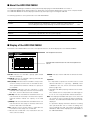
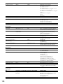
Digital Disk Recorders
Operating Instructions
Model Nos.
TIMER
ALARM
MONITOR1
MONITOR2
1
ERROR
ALARM
SUSPEND
2
SHIFT
ALARM
RESET
9
HDD 1
HDD 2
6
COPY
PAN/
TILT
7
TEXT
8
MARK
11
14
15
STOP
4
OSD
10/0
EL-ZOOM
13
3
SEQ
5
DISK SELECT
OPERATE
WJ-HD309
WJ-HD316
12
LOGOUT
16
ZOOM/
FOCUS
IRIS
PLAY
PAUSE
REC-- REC STOP
GOTO
LAST
A-B
REPEAT
PAN/TILT
SLOW
REV
SEARCH
PULL
FWD
SETUP
/ESC
LISTED
−
PRESET
/AUTO
+
BUSY
SET
Digital Disk
Recorder
WJ-HD
316
Before attempting to connect or operate this product,
please read these instructions carefully and save this manual for future use.
We declare under our sole responsibility that the product to which this
declaration relates is in conformity with the standards or other normative
documents following the provisions of Directives EEC/73/23 and
EEC/89/336.
Wij verklaren als enige aansprakelijke, dat het product waarop deze
verklaring betrekking heeft, voldoet aan de volgende normen of andere
normatieve documenten, overeenkomstig de bepalingen van Richtlijnen
73/23/EEC en 89/336/EEC.
Wir erklären in alleiniger Verantwortung, daß das Produkt, auf das sich
diese Erklärung bezieht, mit der folgenden Normen oder normativen
Dokumenten übereinstimmt. Gemäß den Bestimmungen der Richtlinie
73/23/EEC und 89/336/EEC.
Vi erklærer os eneansvarlige for, at dette produkt, som denne
deklaration omhandler, er i overensstemmelse med standarder eller
andre normative dokumenter i følge bestemmelserne i direktivene
73/23/EEC og 89/336/EEC.
Nous déclarons sous note seule responsabilité que le produit auquel se
réfère la présente déclaration est conforme aux normes ou autres
documents normatifs conformément aux dispositions des directives
CEE/73/23 et CEE/89/336.
Vi deklarerar härmed värt fulla ansvar för att den produkt till vilken
denna
deklaration
hänvisar
är
i
överensstämmelse
med
standarddokument, eller andra normativa dokument som framställs i
EEC-direktiv nr. 73/23 och 89/336.
Nosotros declaramos bajo nuestra única responsabilidad que el producto
a que hace referencia esta declaración está conforme con las normas u
otros documentos normativos siguiendo las estipulaciones de las
directivas CEE/73/23 y CEE/89/336.
Ilmoitamme yksinomaisella vastuullamme, että tuote, jota tämä ilmoitus
koskee, noudattaa seuraavia standardeja tai muita ohjeellisia asiakirjoja,
jotka noudattavat direktiivien 73/23/EEC ja 89/336/EE. säädöksiä.
Noi dichiariamo sotto nostra esclusiva responsabilità che il prodotto a
cui si riferisce la presente dichiarazione risulta conforme ai seguenti
standard o altri documenti normativi conformi alle disposizioni delle
direttive CEE/73/23 e CEE/89/336.
Vi erklærer oss alene ansvarlige for at produktet som denne erklæringen
gjelder for, er i overensstemmelse med følgende normer eller andre
normgivende dokumenter som følger bestemmelsene i direktivene
73/23/EEC og 89/336/EEC.
For U.K.
WARNING:
• To prevent fire or electric shock hazard, do not expose this appliance to
rain or moisture. The apparatus shall not be exposed to dripping or
splashing and that no objects filled with liquids, such as vases, shall be
placed on the apparatus.
• All work related to the installation of this product should be made by
qualified service personnel or system installers.
CAUTION:
• Read the label on the top and bottom of the unit for identification of this
product, and the power ratings.
CAUTION
RISK OF ELECTRIC SHOCK
DO NOT OPEN
CAUTION: TO REDUCE THE RISK OF ELECTRIC SHOCK,
DO NOT REMOVE COVER (OR BACK).
NO USER-SERVICEABLE PARTS INSIDE.
REFER SERVICING TO QUALIFIED SERVICE PERSONNEL.
The lightning flash with arrowhead symbol,
within an equilateral triangle, is intended to
alert the user to the presence of uninsulated
"dangerous voltage" within the product's
enclosure that may be of sufficient magnitude to constitute a risk of electric shock to
persons.
The exclamation point within an equilateral
triangle is intended to alert the user to the
presence of important operating and maintenance (servicing) instructions in the literature accompanying the appliance.
Power disconnection. Unit with or without
ON-OFF switches have power supplied to
the unit whenever the power cord is inserted
into the power source; however, the unit is
operational only when the ON-OFF switch is
in the ON position. The power cord is the
main power disconnect for all units.
2
FOR YOUR SAFETY PLEASE READ THE FOLLOWING TEXT CAREFULLY.
This appliance is supplied with a moulded three pin mains plug for your
safety and convenience.
A 5 amp fuse is fitted in this plug.
Should the fuse need to be replaced please ensure that the replacement
fuse has a rating of 5 amp and that it is approved by ASTA or BSI to
BS1362.
or the BSI mark
on the body of the
Check for the ASTA mark
fuse.
If the plug contains a removable fuse cover you must ensure that it is
refitted when the fuse is replaced.
If you lose the fuse cover the plug must not be used until a replacement
cover is obtained.
A replacement fuse cover can be purchased from your local Panasonic
Dealer.
H
G
IF THE FITTED MOULDED PLUG IS UNSUITABLE FOR THE SOCKET OUTLET IN YOUR HOME THEN THE FUSE SHOULD BE
REMOVED AND THE PLUG CUT OFF AND DISPOSED OF SAFELY.
THERE IS A DANGER OF SEVERE ELECTRICAL SHOCK IF THE
CUT OFF PLUG IS INSERTED INTO ANY 13 AMP SOCKET.
If a new plug is to be fitted please observe the wiring code as shown
below.
If in any doubt please consult a qualified electrician.
WARNING: This apparatus must be earthed.
IMPORTANT
The wires in this mains lead are coloured in accordance with the following code.
Green-and-yellow:
Earth
Blue:
Neutral
Brown:
Live
As the colours of the wire in the mains lead of this appliance may not
correspond with the coloured markings identifying the terminals in your
plug, proceed as follows.
The wire which is coloured green-and-yellow must be connected to
the terminal in the plug which is marked with the letter E or by the earth
symbol I or coloured green or green-and-yellow.
The wire which is coloured blue must be connected to the terminal in
the plug which is marked with the letter N or coloured black.
The wire which is coloured brown must be connected to the terminal
in the plug which is marked with the letter L or coloured red.
How to replace the fuse
Open the fuse compartment with
a screwdriver and replace the fuse
and fuse cover.
FUSE
The serial number of this product may be found on the top
and bottom of the unit.
You should note the serial number of this unit in the space
provided and retain this book as a permanent record of your
purchase to aid identification in the event of theft.
Model No.
Serial No.
CONTENTS
PREFACE .................................................................... 4
FEATURES .................................................................. 4
PRECAUTIONS ........................................................... 5
TRADEMARKS AND REGISTERED
TRADEMARKS ............................................................ 6
ABOUT THESE OPERATING INSTRUCTIONS ......... 6
LIMITATION OF LIABILITY ......................................... 6
MAJOR OPERATING CONTROLS AND
THEIR FUNCTIONS .................................................... 7
■ Front View ............................................................. 7
■ Rear View ............................................................. 9
■ On Monitor 1 (To display only live image) ............. 10
■ On Monitor 2
(To display live or recorded image) ....................... 11
STARTUP .................................................................... 16
CLOCK ADJUSTMENT ............................................... 17
SHUTDOWN ................................................................ 18
RECORDING (Manual Recording) .............................. 19
RECORDING (Emergency Recording) ........................ 21
PLAYBACK .................................................................. 22
PLAYBACK IMAGE ON A DESIGNATED DISK .......... 25
PLAYBACK FROM A DESIGNATED
TIME AND DATE ......................................................... 27
SEARCH AND PLAY ................................................... 28
■ Search for a Recording Event and Play it back
(Recording Event Search) ..................................... 28
■ Search for a motion detected time and date from
recorded images and play it (VMD search) ........... 32
■ To delete the motion detection area ..................... 36
■ Search for a marked point and play from that point
(Marking search) ................................................... 37
MONITOR LIVE IMAGES ............................................ 38
■ Displaying Live Images on a Single Screen .......... 38
■ Electronic Zoom .................................................... 38
■ Displaying on a Multi-screen ................................. 39
■ Sequential Display ................................................ 40
CONTROL CAMERAS ................................................ 41
■ Panning/Tilting ...................................................... 41
■ Zoom ..................................................................... 41
■ Focus .................................................................... 41
■ Iris ......................................................................... 42
■ Preset Action ......................................................... 42
■ Move a camera to the preset position ................... 43
■ Auto Function (Auto Pan, etc) ............................... 44
ABOUT THE EVENT FUNCTION ................................ 45
■ Action at an event occurrence .............................. 45
■ Alarm Function ...................................................... 46
■ Cancel the Alarm Action ....................................... 47
■ Suspend the Alarm Actions ................................... 47
COPYING (Duplicate) .................................................. 48
DELETE DATA ON THE DISK .................................... 50
■ Deletion of recorded images saved on the
hard disk manually ................................................ 50
FORMAT (INITIALIZE) A DVD-RAM DISK .................. 52
DISPLAY/EDIT TEXT INFORMATION ........................ 54
ERROR/WARNINGS ................................................... 56
OPERATION USING A SYSTEM CONTROLLER ...... 58
OPERATION USING A PC .......................................... 62
■ Features ................................................................ 62
■ System Requirements of a PC ...............................62
OPERATION OF THE UNIT IN THE CASCADE
CONNECTION ............................................................. 63
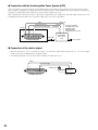
■ Features ................................................................ 63
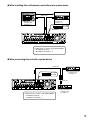
■ Operation using the buttons on the front panel ..... 63
■ Operation using a system controller ..................... 63
INSTALLATION IN THE RACK ................................... 64
MANAGEMENT OF USERS/HOSTS .......................... 65
OPERATING THE UNIT FOR THE FIRST TIME ........ 67
Preparation for maintenance (HDD replacement,
installation, etc.) ........................................................... 68
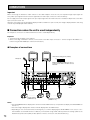
CONNECTIONS .......................................................... 70
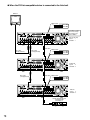
■ Connections when the unit is used
independently ........................................................ 70
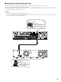
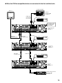
■ Connections with an extension unit ...................... 71
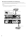
■ Connections with DVD-RAM, CD-R, and
DVD-R drives ........................................................ 72
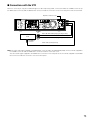
■ Connections with the VTR .................................... 73
■ Connections with PS·Data systems ...................... 74
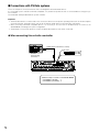
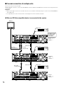
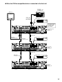
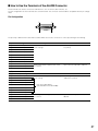
■ Cascade connection of multiple units ................... 76
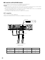
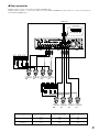
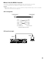
■ Connection with the RS485 camera ..................... 80
■ Mode Switch ......................................................... 82
■ RS485 Port ........................................................... 82
■ How to Use the Terminals of the ALARM/
CONTROL Connector ........................................... 83
■ How to Use the Terminals of the ALARM
Connector ............................................................. 87
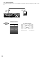
■ How to Use the SERIAL Connector ...................... 89
SETUP ......................................................................... 90
■ Item list of the SETUP MENU ............................... 90
■ About the SETUP MENU ...................................... 92
■ Basic Operation with the SETUP MENU .............. 93
■ [Maintenance] Functions for Maintaining .............. 94
■ [Recording] ............................................................ 98
■ [Event] Function for Events ................................. 100
■ [Schedule] Settings for the recording/
event action schedule ......................................... 105
■ [Switcher] Settings for the switcher function ....... 110
■ [Display] .............................................................. 113
■ [Comm] Settings for communication with other
devices ................................................................ 116
■ [System] Settings on System .............................. 121
DISPLAY SETUP MENU OF CAMERA ..................... 127
DISK MANAGEMENT ................................................ 128
■ Notes on hard disk .............................................. 128
■ How to replace the built-in hard disk ................... 128
■ About the HDD DISK MENU ............................... 131
■ Display of the HDD DISK MENU ........................ 131
■ RAID 5 Function of the Extension Unit ............... 132
■ Formatting (Initialization) the Hard Disk .............. 133
■ Setting for Mirroring ............................................ 137
SERIAL (RS232C) CONNECTOR COMMAND
REFERENCE ............................................................. 141
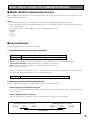
■ SERIAL (RS232C) Communication Protocol ...... 141
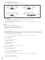
■ Command Format ............................................... 141
FLOWCHART OF THE SETUP MENU ...................... 151
PARAMETERS AND THE DEFAULT SETTINGS
OF THE SETUP MENU ............................................. 152
TROUBLESHOOTING ............................................... 158
SPECIFICATION ....................................................... 162
STANDARD ACCESSORIES .................................... 163
3
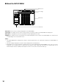
PREFACE
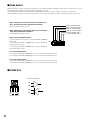
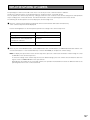
The Digital Disk Recorders WJ-HD316/309 are designed for
use within a surveillance system and are a combination of a
hard disk recorder and a video multiplexer (16-input for the
WJ-HD316, 9-input for the WJ-HD309).
The digital hard disk recorder is a recording device using a
hard disk drive to record camera pictures instead of using
videotapes so that pictures recorded by repeated overwriting will not experience deterioration of the recorded picture
quality. Up to 16 cameras can be connected to the WJ-
HD316 directly (up to 9 cameras to the WJ-HD309) and it is
possible to record their camera pictures. It is also possible
to display four or more camera pictures on a single monitor,
to switch camera pictures, and to operate cameras using
this unit.
FEATURES
Various Recording Functions
• Multi-Recording
It is possible to perform multiple recordings using a single digital disk recorder even if the operating environments are different, for example, recording pictures of
cameras in different places at different times.
Remote Operation via Network
It is possible to operate this unit using a PC connected to a
LAN (Local Area Network) or the Internet with the featured
network function.
Security Function and Reliability
• Schedule recording
It is possible to perform recording automatically at a
scheduled time on a designated day of the week.
Schedules can be set on each camera.
• Authentication function (registration of ID and password) allows users access to a predetermined selection
of the available functions. Up to 32 users can be registered.
• Emergency Recording
In the case of an emergency, emergency recordings
will be given a higher priority than other recording
modes by operating an external switch.
• If alteration of a recorded image data is made for any
reason, the alteration alert function will announce it.
• External Timer Recording
It is possible to perform recording automatically using
an external timer.
• Event Recording
At an event occurrence, such as when an alarm signal
is supplied, the recording mode (quality and recording
rate) can be changed to high quality to record pictures.
• Motion Detection Function (VMD)
It is possible to start recording automatically when
motion is detected in a shooting area.
Frame Switcher Function
• It is possible to display pictures of four or more cameras on a single monitor (multi-screen) splitting the
monitor screen into 4, 7, 9, 10, 13, or 16 sections using
the WJ-HD316, and into 4, 7, or 9 sections using the
WJ-HD309.
While monitoring a multi-screen, each camera picture
will be displayed as a moving image.
4
• If a hard disk crashes, the backup function*1, the mirroring function*2 and the RAID 5 function*3 prevent any
data loss.
*1:
Only when the recommended DVD-RAM drive, DVD-R
drive or CD-R drive is used
*2: The mirroring function does not work with an external
hard disk drive such as an extension unit.
*3: To use the RAID 5 function, an optional extension unit is
required.
Transmission with Coaxial Cable, PS·Data and
RS485 Compatible
• It is possible to control a Panasonic combination camera such as the WV-CS850 using only a coaxial cable
but not other devices. Using a coaxial cable also compensates for transmission loss.
• It is easy to establish the surveillance system by connecting a PS·Data compatible system controller and
peripherals.
PRECAUTIONS
• Refer all work related to the installation of these
products to qualified service personnel or system
installers.
• Do not operate the appliances beyond their specified temperature, humidity, or power source ratings.
Use the appliance at temperatures within +5 °C +45 °C (41 °F - 113 °F) and humidity below 85 %.
The input power source for this appliance is 220 V 240 V AC 50 Hz.
Performance and lifetime of hard disk drives are easily
affected by heat (used at high temperature) characteristically. It is recommended to use this appliance at
temperatures within +20 °C - +30 °C (68 °F - 86 °F).
• Handle the appliance with care.
Do not strike or shake, as this may damage the appliance.
• Do not strike or give a strong shock to the unit.
It may cause damage or allow water to enter the unit.
• Built-in backup battery
Before the first use, charge the built-in backup battery
(lithium battery) by turning on the power for 48 hours or
more.
If it is not charged enough, in a case where the power
goes down, the internal clock may keep bad time or the
operative condition may be different to that before the
electric power failure.
The built-in battery life is approximately 5 years as an
indication of replacement. (This is just an indication of
replacement. We are not providing any guarantee of the
built-in battery lifetime. Replacement cost of the built-in
battery is not covered by the warranty even if it needs
to be done within the warranty period.) Ask the shop
where you purchased the unit when replacement of the
battery is required.
• Cooling Fan
Turn the power off when cleaning the unit. Otherwise it
may cause injuries.
Replacement costs of the cooling fan are not covered
by the warranty even if it needs to be done within the
warranty period. Consult your dealer for servicing.
• Built-in hard disk drives
Hard disk drives are vulnerable to vibration. Handle
them with care.
It is possible to damage them if they are moved while
their motors are still running. Do not move them just
after turning their power on or off (for around 30 seconds).
Hard disk drives are perishable. They will need to be
replaced after around 20 000 - 30 000 hours of operation in case they are used at temperature of 25 °C
(77 °F).
Replacement costs of the hard disk drives are not covered by the warranty even if it needs to be done within
the warranty period. Consult your dealer for servicing.
When hard disk drive trouble occurs, replace it immediately. Consult your dealer for servicing.
When replacing the hard disk drives, take notice of the
following.
Do not detach the hard disk drives or the cables connecting the unit and the front cover while the
HDD1/HDD2 indicators are lit or for around 30 seconds
after the indicators go off.
Protect the hard disk drives from static electricity.
Do not stack them, or keep them upright.
Do not use an electric screwdriver to fix them.
(Tightening torque: Approx. 0.49 N · m (5 kgf · cm))
Avoid rapid changes of the temperature/humidity to
prevent condensation. (Acceptable change: within
15 °C/h (59 °F/h))
• Avoid placing receptacles that contain liquids such as
water near the unit.
If liquid spills onto the unit, it may cause fire or an electric shock.
• Do not expose the unit to water or moisture, or try to
operate it in wet areas.
• Prevent condensation from forming on the surface of
the hard disk.
If this happens, do not turn on the power of the recorder
and leave the recorder for around 2 hours.
Wait until the dew evaporates in any of the following
cases:
• The recorder is placed in an extremely humid place.
• The recorder is placed in a room where a heater has
just been turned on.
• The recorder is moved from an air-conditioned room
to a humid and high-temperature room.
• Cleaning
Turn the power off when cleaning the unit. Otherwise it
may cause injuries.
Do not use strong or abrasive detergents when cleaning the appliance body.
Use a dry cloth to clean the appliance when it is dirty.
When the dirt is hard to remove, use a mild detergent
and wipe gently.
• We recommend that you make a note of your settings
and save them. This will help when you are required to
change the system configuration, or when unexpected
trouble or failure occurs.
• Indication label
Refer to the indication labels placed on the top and buttom of the unit as to the indications of equipment classification and power source, etc.
• Distributing, copying, disassembling, reverse compiling, reverse engineering, and also exporting in violation
of export laws of the software provided with this product, is expressly prohibited.
5
TRADEMARKS AND REGISTERED TRADEMARKS
• Adobe, Adobe logos, and Acrobat are registered trademarks of Adobe Systems Incorporated in the U.S. and/
or other countries.
• Microsoft, Windows and Windows XP are registered
trademarks of Microsoft Corporation in the U.S. and/or
other countries.
• Other names of companies and products contained in
these operating instructions may be trademarks or registered trademarks of their respective owners.
ABOUT THESE OPERATING INSTRUCTIONS
There are 3 sets of operating instructions for the WJHD316/WJ-HD309 as follows.
• Operating Instructions (book, these operating instructions)
• Network Operating Instructions (PDF)
• Network Setup Instructions (PDF)
These "Operating Instructions" contain descriptions of how
to operate this unit with the buttons on the front panel.
Refer to the "Network Operating Instructions" on the provided CD-ROM for descriptions of how to operate this unit
from a PC.
Refer to the "Network Setup Instructions" on the provided
CD-ROM for descriptions of how to perform the required
settings and how to connect to other devices.
Adobe® Reader is required to read these operating instructions (PDF) on the provided CD-ROM. When the Adobe®
Reader is not installed on the PC, download the latest
Adobe® Reader from the Adobe web site and install it.
"WJ-HD300" or "HD300" shown in the illustrations used in
these operating instructions indicate this unit or the WJHD300 series.
LIMITATION OF LIABILITY
IN NO EVENT SHALL MATSUSHITA ELECTRIC INDUSTRIAL CO., LTD. BE LIABLE TO ANY PARTY OR ANY PERSON, EXCEPT FOR REPLACEMENT OR REASONABLE
MAINTENANCE OF THE PRODUCT, FOR THE CASES,
INCLUDING BUT NOT LIMITED TO BELOW:
(1) ANY DAMAGE AND LOSS, INCLUDING WITHOUT LIMITATION, DIRECT OR INDIRECT, SPECIAL, CONSEQUENTIAL OR EXEMPLARY, ARISING OUT OF OR
RELATING TO THE PRODUCT;
6
(2) PERSONAL INJURY OR ANY DAMAGE CAUSED BY
INAPPROPRIATE USE OR NEGLIGENT OPERATION
OF THE USER;
(3) UNAUTHORIZED DISASSEMBLE, REPAIR OR MODIFICATION OF THE PRODUCT BY THE USER;
(4) ANY PROBLEM, CONSEQUENTIAL INCONVENIENCE,
OR LOSS OR DAMAGE, ARISING OUT OF THE SYSTEM COMBINED BY THE DEVICES OF THIRD PARTY.
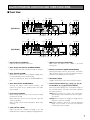
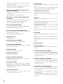
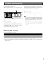
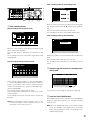
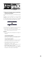
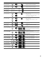
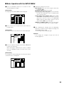
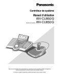
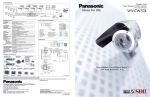
MAJOR OPERATING CONTROLS AND THEIR FUNCTIONS
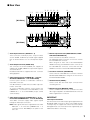
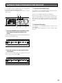
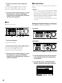
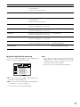
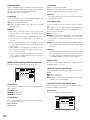
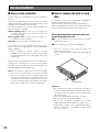
■ Front View
o
t
qw e r yu i
!8 !9 @0
!1 !5 !6 !7
!0
STOP
MONITOR1
MONITOR2
TIMER
ALARM
[WJ-HD316]
ALARM
SUSPEND
OPERATE
1
2
3
SHIFT
SEQ
5
ALARM
RESET
DISK SELECT
HDD 1
COPY
7
8
TEXT
REC - REC STOP
@7 @8 @9
PULL
FWD
S-VIDEO
GOTO
LAST
SEARCH
COPY 2
SETUP
/ESC
PAN/TILT
ZOOM/
FOCUS
A-B SLOW
REPEAT
–
VIDEO
OUT
+
MARK
9
10/0
11
13
14
15
12
LOGOUT
EL-ZOOM
HDD 2
PAUSE
REV
PAN/
TILT
OSD
6
PLAY
4
ERROR
@6
16
IRIS
LISTED
AUDIO
OUT
PRESET
/AUTO
Digital Disk Recorder
SET
BUSY
WJ-HD
!2 !3 !4 @1 @2 @3
o
t
qw e r yu i
!8 !9 @0
!1 !5 !6 !7
!0
STOP
MONITOR1
MONITOR2
TIMER
ALARM
[WJ-HD309]
ALARM
SUSPEND
1
SEQ
TEXT
4
ALARM
RESET
DISK SELECT
HDD 1
HDD 2
PLAY
PAUSE
6
@6
@7 @8 @9
PULL
REV
FWD
S-VIDEO
PAN/
TILT
OSD
#0
REC - REC STOP
3
5
COPY
7
OPERATE
2
ERROR
SHIFT
@4 @5
GOTO
LAST
SEARCH
PAN/TILT
ZOOM/
FOCUS
A-B SLOW
REPEAT
COPY 2
SETUP
/ESC
–
VIDEO
OUT
+
MARK
8
9
LOGOUT
EL-ZOOM
0
IRIS
LISTED
AUDIO
OUT
PRESET
/AUTO
Digital Disk Recorder
SET
BUSY
WJ-HD
!2 !3 !4 @1 @2 @3
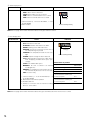
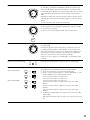
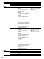
q Operate Indicator (OPERATE)
Lights up when the power is turned on.
w Alarm Suspension Indicator (ALARM SUSPEND)
Lights up when the alarm suspension mode is selected.
e Alarm Indicator (ALARM)
Blinks when an alarm occurs, and lights steadily when
the activated alarm is reset automatically.
To turn this indicator off, press the ALARM RESET button.
r Alarm Reset Button (ALARM RESET)
Pressing this button cancels alarm activation, and
returns the system to the condition before the alarm
was activated.
t Error indicator (ERROR)
Blinks orange when an error occurs that will not keep
the unit from running.
Blinks red when an error occurs that may cause the
system to go down.
Refer to page 56 for further information about error/
warnings.
@4 @5
#0
u HDD Access Indicators (HDD1/HDD2)
Blinks when the HDD1 or the HDD2 is accessed
respectively.
i Monitor Switch button (MONITOR1/MONITOR2)
Pressing this button switches the monitor. This button
lights up when monitor 1 is selected, and goes off when
monitor 2 or the VGA monitor is selected.
o Shift Button (SHIFT)
Toggles the functions of the camera selection buttons.
!0 Camera Selection Buttons ([1] - [10/0], [11] - [16] for
the WJ-HD316, [1] - [9], [0] for the WJ-HD309)
Pressing a button displays live or playback images of
the selected camera. The LED in the button indicates
the status as follows.
Green: When a button is lit green, the currently displayed image on the monitor is live from the respective camera.
Orange: When a button is lit orange, the image from the
respective camera is recorded.
Blue: When a button is lit blue, the currently displayed
image on the monitor is live from the respective
camera and is also recorded.
y Timer Indicator (TIMER)
Lights up when the schedule recording is set, and
blinks while the schedule recording is being performed.
7
When the shift button is lit, these buttons work as the
toggled function buttons.
(The buttons available as the toggled function buttons
will light green when the shift button is lit.)
!1 Pan, Tilt, Latest Recorded Image Playback Button
(PAN/TILT, GO TO LAST)
Pans/tilts the selected camera, or plays back the latest
recorded image.
(Refer to pages 41 and 23 respectively.)
!2 Zoom, Focus, A - B Repeat Button (ZOOM/FOCUS,
A-B REPEAT)
Zooms in/out, adjusts focus, or repeats playback of
recorded images between two designated points.
(Refer to pages 41 and 24 respectively.)
!3 Iris, Listing Button (IRIS, LISTED)
Adjusts iris, or enables/disables the filtering playback.
(Refer to pages 42 and 28 respectively.)
!4 Preset, Auto Function Button (PRESET/AUTO)
Moves a camera to the preset position, or activates the
auto function of the camera.
(Refer to pages 42 and 44 respectively.)
!5 Stop Button (STOP)
Stops playback.
!6 Play/Pause Button (PLAY/PAUSE)
Plays recorded images, or pauses playback.
@3 Set Button (SET)
Works differently depending on the situations listed
below:
• Plays recorded images at the current playback speed
when this button is pressed during fast playback.
• Registers preset positions of cameras.
• Activates the auto focus function.
• Sets the alarm suspension mode on/off.
• Determines the setting of parameters on the setup
menus.
@4 Jog Dial
Works differently depending on the situations as follows:
• Plays recorded images frame by frame when this dial is
rotated during pausing playback.
• Skips playback time when this dial is rotated during
playback at normal speed.
• Moves the cursor on the search menu or the thumbnail
menu.
• Selects a parameter setting or a character on the setup
menus.
@5 Shuttle Ring
Works differently depending on the situations as follows:
• Plays fast when this dial is rotated during playback at
normal speed.
• Turns the search menu pages or the thumbnail menu
pages.
@6 Connectors Cover
!7 Record Button (REC/REC STOP)
Starts recording. To stop recording, press this button
down for 2 seconds or more.
!8 Slow Button (SLOW)
Pans/tilts the selected camera slowly.
!9 Search Button (SEARCH)
Displays the search menu.
@0 Setup, Escape Button (SETUP/ESC)
Displays the setup menu, or turns back to the previous
page of the setup menu, etc.
@1 Busy Indicator (BUSY)
Lights when the selected camera was not available to
operate because another user is operating it using a
controller or a PC via a network. In this case, wait until
this indicator goes off.
@2 Arrow Buttons (CDAB)
Adjusts zooming/focus, or moves the cursor on the
setup menus and the search menu.
8
@7 Copy Port (COPY2)
Connect a recommended external recording device to
this port.
@8 S-Video Output Connector (S-VIDEO)
Connect the S-video input connector of a VTR with this
connector. The same video signal supplied to the MONITOR OUT2 connector on the rear panel will be supplied to this connector.
@9 Video Output Connector (VIDEO OUT)
Connect the video input connector of a VTR with this
connector. The same video signal supplied to the MONITOR OUT2 connector on the rear panel will be supplied to this connector.
#0 Audio Output Connector (AUDIO OUT)
This connector, for an RCA standard jack, supplies an
unbalanced –10 dBV, 600 Ω line output audio signal to
an external device.
Recorded audio will be supplied from this connector
during playback.
The same audio signal supplied to the AUDIO OUT
connector on the rear panel will be supplied to this connector.
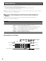
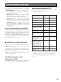
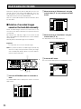
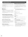
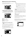
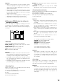
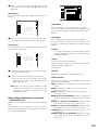
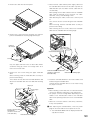
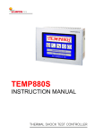
■ Rear View
o !0
q w
3
1
1
4
AUDIO IN
CASCADE
OUT
2
AUDIO OUT
16
15
14
16
15
14
!8
!7
SIGNAL GND
SERIAL
[WJ-HD316]
!1 !3 !5
e !2 !4 !6
t y ui
2
MONITOR OUT CASCADE IN
12
13
MODE
2
1
ALARM
COPY 1
POWER
MONITOR (VGA)
11
10
9
ALARM/CONTOROL
8
7
DATA
6
5
6
5
RS485(CAMERA)
10/100BASE-T EXT STORAGE
4
3
2
1
IN
AC IN
OUT
13
12
11
10
9
VIDEO
8
7
4
3
2
1
r
!9
o !0
q w
3
1
1
2
AUDIO OUT
CASCADE
OUT
2
MONITOR OUT CASCADE IN
MODE
2
1
ALARM
!7
COPY 1
POWER
MONITOR (VGA)
9
[WJ-HD309]
!8
SIGNAL GND
SERIAL
4
AUDIO IN
!1 !3 !5
e !2 !4 !6
t y ui
ALARM/CONTOROL
8
7
DATA
6
5
6
5
RS485(CAMERA)
10/100BASE-T EXT STORAGE
4
3
2
1
IN
AC IN
OUT
9
8
7
4
3
2
1
VIDEO
r
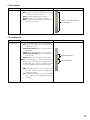
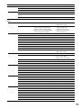
q Audio Input Connectors (AUDIO IN 1 - 4)
These connectors, for RCA pin jacks, accept an unbalanced –10 dBV, 10 kΩ line input audio signal supplied
from an external device such as a microphone amplifier.
w Audio Output Connector (AUDIO OUT)
This connector, for an RCA standard jack, supplies an
unbalanced –10 dBV, 600 Ω line output audio signal to
an external device.
Recorded audio will be supplied from this connector
during playback.
e Video Input Connectors (CAMERA IN 1 - 16 for the
WJ-HD316/CAMERA IN 1 - 9 for the WJ-HD309)
Connect system cameras or combination cameras to
these BNC connectors.
A 75 Ω termination is made unless the video output terminal is connected.
To connect combination cameras, connect them to the
CAMERA IN 1 - 8 connectors of the WJ-HD316, or the
CAMERA IN 1 - 6 of the WJ-HD309 (accept coaxial
communication).
r Video Output Connectors (CAMERA OUT 1 - 16 for
the WJ-HD316/CAMERA OUT 1 - 9 for the WJ-HD309)
These BNC connectors supply video signals looped
through the video input connectors.
Note: Video signals will not be supplied from the CAMERA OUT 1 - 8 connectors (CAMERA OUT 1 - 6
connectors for the WJ-HD309) if the power of the
unit is off.
!9
t Monitor Output Connector (MONITOR OUT1, MONITOR OUT2/CASCADE OUT)
Connect monitors to these BNC connectors.
The MONITOR OUT2 connector can also be used as
the CASCADE OUT connector.
When using two or more units of the WJ-HD316/WJHD309 and using the MONITOR OUT2 connector as
the CASCADE OUT connector, connect with the CASCADE IN connector of another WJ-HD316/WJ-HD309.
y Cascade In Connector (CASCADE IN)
Connect with the CASCADE OUT connector of another
WJ-HD316/WJ-HD309 when using two or more units of
the WJ-HD316/WJ-HD309.
u Serial Connector (SERIAL)
Connect a PC with this D-Sub 9-pin connector when
controlling this unit.
i Monitor Connector (MONITOR (VGA))
Connect a VGA monitor with this connector. The same
video signal supplied to the MONITOR OUT2 connector
will be supplied to this connector.
IMPORTANT
For European Customers
The refresh rate of the video output signal supplied from the
MONITOR (VGA) connector is 50 Hz. Some VGA monitors
in Europe may not support this refresh rate and could be
damaged. Please check the refresh rate supported by your
VGA monitor before connecting.
9
Please check the documentation supplied with your monitor
to see if your VGA monitor supports a refresh rate of 50 Hz.
If your VGA monitor does not support 50 Hz (or if you are
not sure), then turn off your VGA monitor before turning on
WJ-HD316/WJ-HD309 when using your television as a display.
o Alarm Connector (ALARM)
Connect an external device such as a sensor or a door
switch with this D-Sub 25-pin connector.
!0 Alarm/Control Connector (ALARM/CONTROL)
Connect a control switch with this D-Sub 25-pin connector when controlling this unit using an external
device, or when controlling an alarm device such as a
buzzer or a lamp.
!1 PS·Data Ports (DATA)
Connect PS·Data compatible devices with these ports.
!2 Mode Switches (MODE)
Set the operation mode of this unit with these dip
switches.
!3 RS485 Ports (RS485 (CAMERA))
Connect RS485 compatible combination cameras with
these ports.
!4 Network Port (10/100BASE-T)
Connect this unit to a network compatible with 10BASET or 100BASE-Tx when controlling this unit using a PC
via a network.
!5 Copy Port (COPY1)
Connect a recommended external recording device to
this port.
!6 Extra Storage Port (EXT STORAGE)
Connect an optional extension unit (WJ-HDE300 series)
with this port.
!7 Power Switch (POWER)
Turns the power of this unit on and off.
!8 Signal Ground Terminal (SIGNAL GND)
!9 Power Cord Inlet (AC IN)
Connect the power cord to this inlet.
10
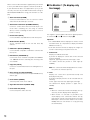
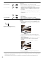
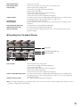
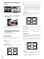
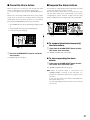
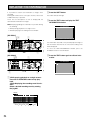
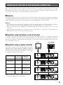
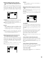
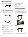
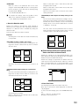
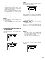
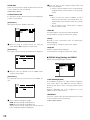
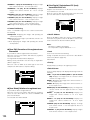
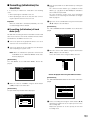
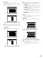
■ On Monitor 1 (To display only
live image)
q
we
q
we
q
q
we
q
we
The negative circled numbers indicate the default positions
of camera title q, time w and event display e.
Important:
• The SETUP MENU will be displayed on monitor 2 and
the VGA monitor. (It is impossible to display the SETUP
MENU on monitor 1.)
• It will take around 2 minutes to display live images on
monitor 1 after turning on the power of the unit.
1. Camera Title
Displays the edited camera title.
A position to display the camera title can be selected
from the following.
Upper left, upper right, lower left, lower right, centre
The default camera title position is lower right (RLOWER).
Note: The camera title will be displayed with 16 characters (2 lines: 8 characters per line).
2. Time
Displays the current time (hour:minute:second) and
date (day:month:year).
A position to display the time can be selected from the
following.
Centre, upper left, lower left, upper right, lower right
The default time display position is upper left (LUPPER).
Notes:
• When the camera title and the time display are layered, only the time display will be displayed.
• When monitor 1 is selected, it is possible to turn
on/off display of the camera title and the time by
pressing the camera selection button 8 for the WJHD316 (the camera selection button 6 for the WJHD309) while the shift function is on (by pressing
the SHIFT button).
3. Event Display
When an event has occurred, an event display will be
displayed.
The position of an event display will be symmetrical to
the position where the time is displayed. When the time
is displayed at the lower left of the screen, an event display will be displayed at the upper right corner of the
screen. The default position of an event display is the
upper right corner of the screen (R-UPPER).
The event display will be displayed differently as follows
depending on which event has occurred.
VMD-*: When motion is detected.
LOSS-*: When video loss has occurred.
COM-#: When a command alarm has occurred.
TRM-#: When a terminal alarm has occurred.
*: Camera number (1 - 16 for the WJ-HD316, 1 - 9 for
the WJ-HD309)
#: Alarm number
Note: Refer to page 45 for further information about
event types and event actions.
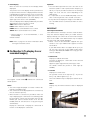
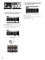
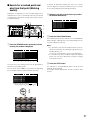
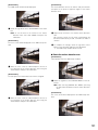
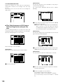
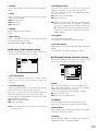
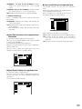
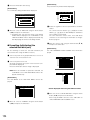
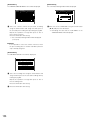
■ On Monitor 2 (To display live or
recorded images)
q
q
w
–
–
w
q
B
C
q
q
w–A
The negative circled number q indicates the camera title
default position.
Notes:
• The same images displayed on monitor 2 will be displayed on the VGA monitor.
• The camera title will be displayed with 16 characters (2
lines: 8 characters per line).
• When monitor 2 is selected, it is possible to switch the
way of displaying the camera title in the following order
by pressing the camera selection button 8 for the WJHD316 (the camera selection button 6 for the WJHD309) while the shift function is on (by pressing the
SHIFT button):
Display the camera title → Display the camera title in
list form → Not display the camera title
Important:
• Since the VGA output from this unit is the same as for
televisions (720 H x 576 V pixels/vertical frequency of
50 Hz), it may be possible that both the left and right
edges can not fit onto the screen depending on the
VGA monitor.
• It is impossible to use the MONITOR (VGA) connector
when connecting the unit in the cascade connection.
• It may take time to display live images on the VGA monitor if the VGA monitor is turned on/off when the unit is
running.
IMPORTANT
For European Customers
Some VGA monitors in Europe cannot be used simultaneously with television display. When you enable television
display in Europe, the refresh rate for the monitor and television is set to 50Hz. Some VGA monitors may not support
this refresh rate and could be damaged.
• Please check the documentation supplied with your
monitor to see if your VGA monitor supports a refresh
rate of 50 Hz.
If your VGA monitor does not support 50 Hz (or if you
are not sure), then turn off your VGA monitor before
turning on WJ-HD316/WJ-HD309 when using your television as a display.
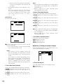
1. Camera Title
Displays the edited camera title.
A position to display the camera title can be selected
from the following.
Upper left, upper right, lower left, lower right, centre
The default camera title position is lower right (RLOWER).
2. Task Bar
Displays the current status.
The task bar consists of the main bar (w - A), the left
bar (w - B), and the right bar (w - C).
There are 3 different ways to display the task bar as follows.
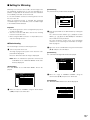
Mode 1
Displays only the main bar and the status is displayed
on it.
11
Note: When the camera title and the task bar are layered in this mode, only the task bar will be displayed.
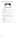
Mode 2
Displays the status on the main bar, the left bar and the
right bar.
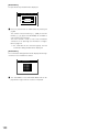
Mode 3
Displays the status only on the main bar, and does not
display information on the left bar and the right bar.
Note: Mode 2 and Mode 3 are graphic operated. They
may not be as clear as Mode 1.
12
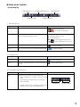
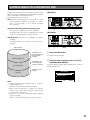
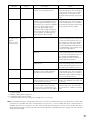
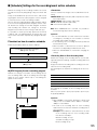
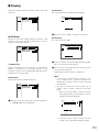
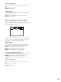
● Status on the Task Bar
• On the Main Bar
q Status Display Area
e Live/Playback Time Display Area
w Copy/Delete Icons
t Error Display Area
r Alarm Display Area
q Status Display Area
Indicated Item
Status
Indication
Live
Indicates the live image display status
: Live image is displayed
: Live images are displayed
sequentially
Playback
Indicates that playback is currently being performed
with the displayed playback speed
5: Currently playing
4: Currently playing in reverse
h: Currently pausing
2
: Currently playing at fast speed
1
: Currently playing in reverse at fast
speed
Recording
Indicates that recording is currently being performed
Search
Indicates that searching is currently being performed
: Currently recording
: Currently searching
w Copy/Delete Icons
Indicated Item
Status
Indication
Copy
Indicates that data copy is currently being performed
: Currently copying
Delete
Indicates that data deletion is currently being performed
: Currently deleting data
e Live/Playback Time Display Area
Indicated Item
Time
Status
Indication
Displays time and date of the displayed image
When displaying live image: Current time and
date
When playing recorded image: Time and date
when recorded
Year:Month:Day
Hour:Minute:Second
*: During summer time, an asterisk (*) will be displayed on the left side of the displayed time.
13
r Alarm Display Area
Indicated Item
Alarm
Status
Indication
Indicates that an alarm has occurred
VMD-*: When motion is detected
LOSS-*: When video loss has occurred
COM-*: When a command alarm has occurred
TRM-*: When a terminal alarm has occurred
Alarm type
*: Camera number (1 - 16 for the WJ-HD316, 1 - 9 for
the WJ-HD309)
#: Alarm number
Alarm is occurring currently
Note: Refer to page 45 for further information about event types and event actions.
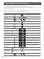
t Error Display Area
Indicated Item
Error Warning
Status
Indicates an error occurrence or warning
ALT-*: Alteration is detected
W-ERROR: Failed to write data on the HDD
SMART: Warning of the HDD malfunction
H-METER: Set time for hour-meter (active time of
the HDD) warning has passed
THERMAL: The temperature inside the unit is too
high
POWER: A power outage has been detected
#-nn%: Warning about running out of disk space
while displaying available disk space percentage
#-FULL: No available disk space
MEDIUM-n: An error occurred in an external
recording device
REMOVE: The hard disk is removed from the system automatically because of an access error
FAN: The fan is faulty
*: Camera number (1 - 16 for the WJ-HD316, 1 - 9
for the WJ-HD309)
#: Abbreviation that indicates partition
nn: Available disk size
n: Number of connector that an external recording
device is connected to
Indication
Error type
Error is occurring currently
Abbreviation of partition
Status
Normal recording area
Event recording area
Copy area
External recording device
connected to the COPY1 port
on the rear panel
External recording device
connected to the COPY2 port
on the front panel
Note: Refer to page 56 for further information about error types and what to do when an error has occurred.
14
Displayed
abbreviation
NML
EVT
CPY
CP1
CP2
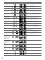
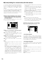
• On the Left Bar
Status
Indicated Item
Camera
Indicates recording and displaying status
Grey: Camera currently not displayed or not connected to the respective channel
Green: Camera displayed on the monitor
Orange: Camera currently being recorded
Blue: Camera currently being recorded and displayed on the monitor
Indication
Camera 1 is on the top and camera
16 is on the bottom
• On the Right Bar
Indicated Item
Used disk space
Status
Indicates the available disk space of each partition.
Top: 100 % of the disk space is being used (no
available disk space)
Second from the top: 80 % of the disk space is
being used
Centre: 60 % of the disk space is being used
Second from the bottom: 40 % of the disk space
is being used
Bottom: 20 % of the disk space is being used
Note: When "CONTINUE" is selected on the "Disk End
Mode" page of the "Maintenance" setup menu, the
available disk space will not be displayed. Refer
to a system administrator for further information.
Indication
Normal Recording Area
Event Recording Area
NML: Available disk space of the normal recording area used for manual recording and
schedule recording
EVT: Available disk space of the event recording
area used for event recording and emergency
recording
15
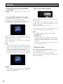
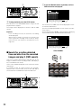
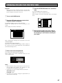
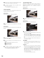
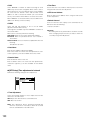
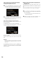
STARTUP
z Insert the power plug to an outlet (AC 220 V -
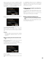
c Enter a user name and password.
240 V, 50 Hz)
Note: Make sure the power source is AC 220 V - 240 V,
50 Hz.
x Turn on the power switch on the rear panel.
The OPERATE indicator will light and the system check
(checking the system and hard disk) will start.
The startup splash image below will be displayed on monitor 2 and the VGA monitor during the system check.
Rotate the jog dial to select a character to be entered in the
cursor position.
It is also possible to enter numbers by pressing the camera
selection buttons ([1] - [10/0] for the WJ-HD316, [1] - [9],
[0] for the WJ-HD309).
To move the cursor, press the arrow buttons.
Use the same method to enter or edit characters attached
to images. Refer to page 54 for further information.
When the auto login is off, the login window will be displayed if any button on the front panel of this unit is pressed
after the system check. (Go to step 3)
When the auto login is on, live images will be displayed
after the system check.
Notes:
• If the hard disk configuration was changed after the last
startup or the hard disk has problems, the HDD DISK
MENU will be displayed automatically after the startup
splash. (Refer to page 131 for further information.)
• It is possible to display the disk configuration menu by
pressing the SET button when the image displayed
below that says the system check has been completed.
Important:
When using the optional extension unit (WJ-HDE300
series), turn on the power of this unit after turning on the
power of all extension units.
16
Notes:
• The default user name and password are as follows:
User name: ADMIN
Password: 12345
• To enhance the security, change the password for an
administrator before starting to run the unit. It is recommended to change the password for an administrator
periodically.
• To log out, press the LOGOUT button after confirming
that the SHIFT indicator is lit.
v Display a live image.
Press the SET button to display a live image.
If the authentication (login) window is displayed, enter the
user name and password.
When authenticated, a live image will be displayed.
When not authenticated, the authentication (login) window
will be displayed again.
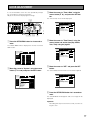
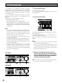
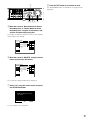
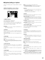
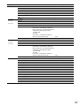
CLOCK ADJUSTMENT
It is recommended to check the clock periodically and put
the clock right if it shows the wrong time.
Adjust the clock when displaying a live image.
STOP
1
2
SHIFT
3
SEQ
5
DISK SELECT
9
7
TEXT
10/0
13
14
PAUSE
REC - REC STOP
SETUP MENU
A-B SLOW
REPEAT
ZOOM/
FOCUS
Basic Setup
SETUP
/ESC
PAN/TILT
8
FWD
SEARCH
Time & Date
–
MARK
12
11
LOGOUT
EL-ZOOM
GOTO
LAST
PAN/
TILT
OSD
6
COPY
PLAY
REV
4
IRIS
User Regist.
+
16
User Delete
Host Regist.
Host Edit
SET
Recording
Event
Schedule
Switcher
Display
Comm
System
1
.
JAN .
LIVE
DD.MMM.YY
12H
03
12
00 : 00 AM
■ Auto Adjust Time
Master Time
■ Summer Time(Day Light Saving)
■ Summer Time(Day Light Saving)Table
SET
OFF
12 :00 AM
AUTO
SETUP
Host Delete
316
BUSY
Maintenance
■ Date Format
■ Time Format
■ Time & Date
User Edit
LISTED
PRESET
/AUTO
LOGOUT
15
arrows button (C D), and press the SET button.
The "Time & Date" menu will be displayed.
zn
MONITOR1
MONITOR2
c Move the cursor to "Time & Date" using the
User Level
Save/Load
xcv cb v
z Press the SETUP/ESC button for 2 seconds or
more.
The SETUP MENU will be displayed on monitor 2 and the
VGA monitor.
v Move the cursor to "Time Format" using the
arrows button and set the time (Day, Month,
Year, Time) using the jog dial.
SETUP MENU
SET UP MENU
Basic Setup
Maintenance
Recording
Switcher
Display
Version Info
Disk End Mode
Disk Capacity
Date Delete
Schedule
System
Comm
User Regist.
SCHE
AUTO
1ips
1ips
1ips
1ips
CAM 2
AUTO
1ips
1ips
1ips
1ips
CAM 3
AUTO
1ips
1ips
1ips
1ips
Host Regist.
CAM 4
AUTO
1ips
1ips
1ips
1ips
Host Edit
CAM 5
AUTO
1ips
1ips
1ips
1ips
CAM 6
AUTO
1ips
1ips
1ips
1ips
CAM 7
AUTO
1ips
1ips
1ips
1ips
CAM 8
AUTO
1ips
1ips
1ips
1ips
CAM 9
AUTO
CAM 10
PRE EVT POST EVT
EMR
Recording
Event
Schedule
Switcher
Display
Comm
System
User Delete
1
.
JAN .
LIVE
DD.MMM.YY
12H
03
12 : 00 : 00 AM
User Edit
■ Auto Adjust Time
Master Time
■ Summer Time(Day Light Saving)
■ Summer Time(Day Light Saving)Table
SET
OFF
12 :00 AM
AUTO
SETUP
Host Delete
User Level
Save/Load
1ips
1ips
1ips
1ips
AUTO
1ips
1ips
1ips
1ips
CAM 11
AUTO
1ips
1ips
1ips
1ips
Event Log
CAM 12
AUTO
1ips
1ips
1ips
1ips
Error Log
CAM 13
AUTO
1ips
1ips
1ips
1ips
SUPER FINE
CAM 14
AUTO
1ips
1ips
1ips
1ips
FINE
CAM 15
AUTO
1ips
1ips
1ips
1ips
NORMAL
CAM 16
AUTO
1ips
1ips
1ips
1ips
EXTENDED
Access Log
Time & Date
LIVE
MANU
CAM 1
REC Rate
Disk Info
Event
Maintenance
■ Date Format
■ Time Format
■ Time & Date
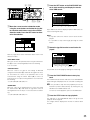
b Move the cursor to "SET" and press the SET
x Move the cursor to "System" using the arrows
button (C D A B) and press the SET button.
button.
The selected date format and the set time will be applied.
SETUP MENU
SETUP MENU
Maintenance
Recording
Event
Schedule
Switcher
Display
Comm
System
Basic Setup
Basic Setup
Time & Date
User Regist.
User Edit
User Delete
■ ADMIN Password
Time & Date
*****
User Regist.
■ PSD User
ON
User Delete
Auto Login User
Host Regist.
ADMIN
Host Regist.
Host Edit
Host Delete
User Level
Save/Load
■ Auto Logout
■ Priority
■ "GO TO LAST" before
■ Language
■ Beep(Operation)
■ Buzzer(Error)
■ Shutdown Time
■ Auto Copy
Recording
Event
Schedule
Switcher
Display
Comm
System
■ Date Format
■ Time Format
■ Time & Date
LIVE
1
.
JAN .
DD.MMM.YY
12H
03
12 : 00 : 00 AM
User Edit
ADMIN
■ Auto Login
Maintenance
LIVE
Host Edit
OFF
Follow the priority.
5s
ENGLISH
ON
2s
10s
OFF
■ Auto Adjust Time
Master Time
■ Summer Time(Day Light Saving)
■ Summer Time(Day Light Saving)Table
SET
OFF
12 :00 AM
AUTO
SETUP
Host Delete
User Level
Save/Load
n Press the SETUP/ESC button for 2 seconds or
more.
The SETUP MENU will disappear and a live image will be
displayed.
Important:
Recording will stop for around 4 seconds just after setting the clock.
17
SHUTDOWN
To shutdown the unit, do the following.
When recording is being performed, press the REC button
for 2 or more seconds. Recording will stop and the indicator on the REC button will go off.
When playback is being performed, press the STOP button.
Playback will stop and the indicator on the PLAY/PAUSE
button will go off.
Turn off the power of the unit after confirming that the HDD1
and HDD2 indicators are off.
Important:
• Detach the plug from the outlet if not operating the unit
for a length of time.
• When the unit has not been used for a certain period,
turn on the power of the unit (approximately once a
week), and perform recording/playback to prevent
interferences with functions.
18
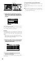
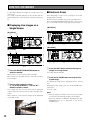
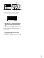
RECORDING (Manual Recording)
Do the following to record manually.
Refer to a system administrator about the required settings
for manual recording.
When recording with higher priority than manual recording
is performed, manual recording will not be performed until
this recording finishes.
Refer to the following about the recording mode.
zx
x Stop recording.
STOP
MONITOR1
MONITOR2
R
1
2
3
4
R
SHIFT
SEQ
5
DISK SELECT
1
2
OSD
6
COPY
7
TEXT
9
10/0
13
14
PAUSE
REC - REC STOP
REV
PAN/
TILT
GOTO
LAST
8
ZOOM/
FOCUS
A-B
REPEAT
11
12
IRIS
LISTED
15
LOGOUT
16
FWD
SEARCH
PAN/TILT
SLOW
SETUP
/ESC
–
MARK
LOGOUT
EL-ZOOM
PLAY
+
PRESET
/AUTO
SET
BUSY
z Start recording.
Press the REC button to start recording.
The indicator on the button will light and recording will start.
Images from all the connected cameras will be recorded
with the default setting.
It is possible to record only images displayed on monitor 2
and the VGA monitor by changing the settings.
Press the REC button down for around 2 seconds.
The indicator on the button will go off and recording will
stop.
Notes:
316
• The camera selection button will light orange (currently
recording) or blue (currently being recorded and displayed on the monitor) to indicate which camera is
being recorded.
• When recording with other recording modes being performed, the indicator on the REC button will not go off
even though the REC button is pressed to stop manual
recording.
● Recording Mode and Priority
There are 4 recording modes as follows.
Recording Mode
Description
Priority*1
Emergency Recording
Start recording manually using an external switch at an emergency event occurrence Highest
Event Recording
Recording will be performed automatically at an event occurrence
1*2
Manual Recording
Start and stop recording manually
2*2
Schedule Recording
Recording will be performed automatically with a designated start/stop time and date
3*2
*1: Priorities on the above table are the default settings. (Emergency recording is the highest priority.)
*2: Priorities for manual recording, schedule recording and event recording can be changed. Refer to a system administrator
about the settings.
19
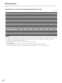
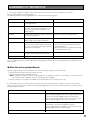
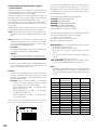
● Recording Time
The possible recording durations on the following table are just the average values. (Refer to the important notice below the
table.)
Recording rate for a single camera channel (Recording without audio)
Unit: Hour
Recording Rate [ips]
0.1
0.2
0.3
0.4
0.5
1
1.7
2.5
4.2
5
6.3
8.3
12.5
25
50
SFA
19 000
9 500
6 300
4 700
3 800
1 900
1 100
700
400
300
300
200
100
70
30
SFB
12 700
6 300
4 200
3 100
2 500
1 200
700
500
300
200
200
100
100
50
20
FQA
25 400
12 700
8 400
6 300
5 000
2 500
1 400
1 000
600
500
400
300
200
100
50
FQB
19 000
9 500
6 300
4 700
3 800
1 900
1 100
700
400
300
300
200
100
70
30
NQA
38 100
19 000
12 700
9 500
7 600
3 800
2 200
1 500
900
700
600
400
300
100
70
NQB
25 400
12 700
8 400
6 300
5 000
2 500
1 400
1 000
600
500
400
300
200
100
50
EXA
50 800
25 400
16 900
12 700
10 100
5 000
2 900
2 000
1 200
1 000
800
600
400
200
100
EXB
38 100
19 000
12 700
9 500
7 600
3 800
2 200
1 500
900
700
600
400
300
100
70
Important:
The possible recording durations on the above tables are the average durations under the conditions below. The possible
recording durations varies depending on images to be recorded. Refer to a system administrator for further information.
• Recording on the built-in hard disk (160 GB x 1)
• Recording images from a single camera channel by manual recording
• Resolution: FIELD
• Color Mode: COLOR STD (The color mode setting is available only using a PC via a network.)
• Recording without audio (When recording with audio, disk usage will be at the rate of 79.2 MB per hour.)
20
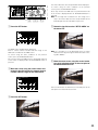
RECORDING (Emergency Recording)
Record manually using an external switch at an emergency
event occurrence.
For example, install an external switch at the reception
counter, and start recording with it when a suspicious individual appears.
Refer to a system administrator about the required settings
for emergency recording.
• When starting emergency recording while another
recording with a different recording mode (except event
recording) is being performed, the indicator on the REC
button will remain lit and the other recording will resume
after the emergency recording has finished.
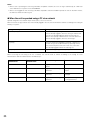
● Recording duration of emergency
recording
Recording duration of emergency recording can be set as
follows. Refer to a system administrator for further information.
z
STOP
MONITOR1
MONITOR2
TIMER
ALARM
ALARM
SUSPEND
OPERATE
1
2
5
6
3
4
ERROR
SHIFT
ALARM
RESET
HDD 1
SEQ
DISK SELECT
COPY
TEXT
9
10/0
13
14
PAN/
TILT
GOTO
LAST
ZOOM/
FOCUS
12
IRIS
Parameter
REC - REC STOP
A-B SLOW
REPEAT
LOGOUT
15
16
Recording Duration
1 s - 10 s
SEARCH
PAN/TILT
8
PAUSE
SETUP
/ESC
–
MARK
11
LOGOUT
EL-ZOOM
HDD 2
OSD
7
PLAY
LISTED
PRESET
/AUTO
SET
BUSY
x
z Press the external switch.
The indicator on the REC button will light and recording will
start.
With the default setting, recording will be performed for 10
seconds.
Record for the selected time (1 - 10 seconds, can be set in 1 second intervals)
20 s
Record for 20 seconds
30 s
Record for 30 seconds
1 m - 10 m 316 Record for the selected time (1 -10 minutes can be set in 1 minute intervals)
20 m - 60 m
Record for the selected time (20 - 60 minutes, can be set in 10 minutes intervals)
MANUAL
Record only while the external switch is
being pressed down
CONTINUE
Record until the ALARM RESET button is
pressed
Emergency recording is the highest priority. Emergency
recording will be performed even when this unit is recording in other recording modes.
x Stop recording.
When the recording duration set in advance has passed,
recording will stop automatically.
With the default setting, recording will stop automatically
after recording for 10 seconds.
When "CONTINUE" is selected for "Recording Time" of
"Emergency REC" on the SETUP MENU (Recording), press
the ALARM RESET button to stop recording.
The indicator on the REC button will go off and recording
will stop.
Important:
• The camera selection button will light orange (currently
recording) or blue (currently being recorded and displayed on the monitor) to indicate which camera is
being recorded.
21
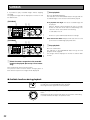
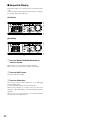
PLAYBACK
It is possible to play recorded images without stopping
recording.
The playback images will be displayed on monitor 2 and
the VGA monitor.
x Start playback.
[WJ-HD316]
First playback after login: The latest recorded image will
be played.
With the default setting, playback will start 5 seconds
before the start time of the latest recorded image. The
start time can be selected from the following:
5 s/10 s/30 s/1 m/5 m
c x
z
STOP
MONITOR1
MONITOR2
R
1
2
3
SEQ
5
DISK SELECT
OSD
6
COPY
7
TEXT
8
GOTO
LAST
REC - REC STOP
SETUP
/ESC
PAN/TILT
ZOOM/
FOCUS
FWD
SEARCH
A-B SLOW
REPEAT
–
+
MARK
9
10/0
11
13
14
15
12
LOGOUT
EL-ZOOM
2
PAUSE
REV
PAN/
TILT
R
SHIFT
PLAY
4
16
IRIS
LISTED
PRESET
/AUTO
Refer to a system administrator about the settings.
SET
BUSY
Other than those above: Playback will start from the end
point of the recorded image played last time.
[WJ-HD309]
c x
z
STOP
MONITOR1
MONITOR2
R
1
2
SEQ
TEXT
4
DISK SELECT
5
7
6
GOTO
LAST
REC - REC STOP
SETUP
/ESC
PAN/TILT
A-B SLOW
ZOOM/
FOCUS
REPEAT
IRIS
LISTED
c Stop playback.
FWD
SEARCH
–
+
MARK
8
9
LOGOUT
EL-ZOOM
0
2
PAUSE
REV
PAN/
TILT
OSD
COPY
PLAY
3
R
SHIFT
Press the PLAY/PAUSE button.
The indicator on the PLAY/PAUSE button will light and the
recorded images of the selected camera will be played.
PRESET
/AUTO
SET
BUSY
Press the STOP button.
The indicator on the PLAY/PAUSE button will go off and
playback will be stopped.
Live images will be displayed on monitor 2 and the VGA
monitor.
z Select the camera respective to the recorded
images to be played. (Go to step 2 if not necessary)
Press the desired camera selection button.
The pressed camera selection button will light green or
blue and the respective live images will be displayed.
● Available functions during playback
Pause
PLAY
Single frame skip
REV
–
22
Pressing the PLAY/PAUSE button to pause playback. While pausing,
the indicator on the PLAY/PAUSE button will blink.
Pressing this button again will resume playback.
PAUSE
FWD
+
Rotating the jog dial during pause will skip to the next or previous
frame.
Rotating the jog dial clockwise will skip to the next frame and rotating
it counterclockwise will skip to the previous frame.
Fast forward/Fast reverse
REV
FWD
–
+
Hold playback speed
REV
FWD
–
+
Rotating the shuttle ring will change the playback speed (1/2x, 1x, 2x,
5x, 10x, 20x) according to rotated degree. When the shuttle ring is
held in the 20x position (rotated to the end) for 5 seconds, the playback speed will be 50x. When the shuttle ring is held 5 more seconds
after the playback speed became 50x, the playback speed will be
100x.
Rotating the shuttle ring clockwise will play images at a faster speed
and rotating it counterclockwise will play images in reverse at a faster
speed.
To play at normal speed, release the shuttle ring.
Press the SET button while holding the rotated shuttle ring to hold a
desired playback speed. (Playback speed will be held even though
the shuttle ring is released.)
To return to the normal playback speed, press the SET button.
+
SET
Skip
REV
FWD
–
Play the latest recorded image
+
PAN/
TILT
GOTO
LAST
Multi-screen display
SHIFT
+
···
(For the WJ-HD316)
SHIFT
SHIFT
+
6
1
···
(For the WJ-HD309)
+
1
SHIFT
+
3
Rotating the jog dial during playback will skip to the next or previous
recorded image.
Rotating the jog dial clockwise will skip to the start time of the next
recording and start playback, and rotating it counterclockwise will
skip to the start time of the previous one. (Rotating the jog dial counterclockwise at the point around the start time of the recording will
skip to the start time of two more previous recordings).
If there is no next or previous recorded image, current playback will
continue.
Press the GO TO LAST button to play the latest recorded image.
It is possible to display recorded images in multi-screen format
(4/7/9/10/13/16 for the WJ-HD316, 4/7/9 for the WJ-HD309).
q Press the SHIFT button. The SHIFT indicator will light.
w Press a camera selection button (1 - 6 for the WJ-HD316, 1 - 3 for
the WJ-HD309) to select a desired multi-screen.
Camera selection button 1: 4-split screen
Camera selection button 2: 7-split screen
Camera selection button 3: 9-split screen
Camera selection button 4: 16-split screen (Only for the WJHD316)
Camera selection button 5: 10-split screen (Only for the WJHD316)
Camera selection button 6: 13-split screen (Only for the WJHD316)
e To display recorded images on a single screen, press the SHIFT
button again.
After the SHIFT indicator goes off, press the camera selection button.
23
Marking
(For the WJ-HD316)
SHIFT
(For the WJ-HD309)
SHIFT
+
Mark
+
Mark
+
TEXT
+
TEXT
12
9
Text display
(For the WJ-HD316)
SHIFT
(For the WJ-HD309)
SHIFT
A - B repeat playback
ZOOM/
FOCUS
A-B
REPEAT
11
5
It is possible to play from a marked point. Do the following to mark a
desired point.
1. Press the SHIFT button. The SHIFT indicator will light.
2. Press the camera selection button 12 (9 for the WJ-HD309) (MARK)
at a desired point to be marked during playback.
Up to 100 points can be marked. When more than 100 points are
marked, the older marked points will be overwritten by the newer
marked points. In this case, the oldest marked point is the first to
be overwritten.
When marked while displaying in multi-screen, the same number of
split screens will be counted as marked points. (When a point is
marked while displaying a 16-split screen, 16 points will be marked
simultaneously.)
It is possible to display text information attached to a recorded image
during playback.
Text display is available only when playing on a single screen.
q Pause playback.
w Press the SHIFT button. The SHIFT indicator will light.
e Press the camera selection button 11 (5 for the WJ-HD309) (TEXT).
It is possible to play recorded images between two designated points
repeatedly.
q Designate a start point (A) by pressing the A - B REPEAT button
during playback.
The A - B REPEAT indicator will light, and the time of point A will
be displayed.
Blink: During the A-B repeat playback
Light: When designating a start point (A)
Time of point A
To cancel the designated point, press the SETUP/ESC button.
w Designate an end point (B) by pressing the A - B REPEAT button
during playback.
When the start point and the end point are set, the A - B REPEAT
indicator will start blinking.
Playback between point A and B will start and keep playing
repeatedly.
The time of point A and B will be displayed during playback.
Time of point A and B
e Press the A - B REPEAT button during A - B repeat playback to
return to normal playback.
Notes:
• Playback will be paused if the playback time caught up with the recording time (present time) when recording and playback are performed simultaneously.
• When playing images recorded at a high recording rate, unsteady playback speed and audio break-up may occur.
24
PLAYBACK IMAGE ON A DESIGNATED DISK
Images from a camera will be recorded on the built-in hard
disk or external recording devices (DVD-RAM drive, DVD-R
drive or CD-R drive) connected to this unit.
Available disk areas are as follows.
Note: External recording devices can be used as a copy
area for images recorded on the hard disk. It is impossible to record images on the external recording
devices directly.
HDD Normal Recording Area/Event Recording Area:
Disk space for recording on the built-in hard disk
Recorded images by manual recording (refer to page
19) or event recording will be stored in this area.
[WJ-HD316]
STOP
MONITOR1
MONITOR2
R
1
2
3
SEQ
5
DISK SELECT
OSD
6
COPY
7
TEXT
z
A-B SLOW
REPEAT
ZOOM/
FOCUS
9
10/0
11
13
14
15
12
LOGOUT
16
IRIS
+
PRESET
/AUTO
SET
BUSY
[WJ-HD309]
STOP
1
2
SHIFT
SEQ
TEXT
4
DISK SELECT
5
7
REC - REC STOP
6
ZOOM/
FOCUS
REPEAT
IRIS
LISTED
FWD
SEARCH
PAN/TILT
A-B SLOW
SETUP
/ESC
–
+
MARK
8
9
LOGOUT
EL-ZOOM
0
2
PAUSE
REV
GOTO
LAST
PAN/
TILT
OSD
COPY
PLAY
3
R
z
Recording area for
manual recording and
normal schedule
recording
–
LISTED
MONITOR1
MONITOR2
Built-in hard disk
SETUP
/ESC
PAN/TILT
8
FWD
SEARCH
x
R
HDD Copy Area: Disk space for recording on the built-in
hard disk
Recorded images will be copied in this area (refer to
page 48).
REC - REC STOP
MARK
EL-ZOOM
2
PAUSE
REV
GOTO
LAST
PAN/
TILT
R
SHIFT
PLAY
4
PRESET
/AUTO
SET
BUSY
x
z Press the SHIFT button.
The SHIFT indicator will light.
Normal recording area
Recording area for
event recording and
emergency recording
Event recording area
Recording area for
copying
x Press the camera selection button 9 (7 for the
WJ-HD309) (DISK SELECT).
The DISK SELECT window will be displayed on monitor 2
and the VGA monitor.
DISK SELECT
Copy area
HDD NORMAL/EVENT AREA
HDD COPY AREA
Notes:
• Playback images will be displayed only on monitor 2
and the VGA monitor.
• Playback can be performed during recording.
• When a pre-recording area is created in an optional
extension unit, it is possible to play the images recorded on the pre-recording area.
• Disk space size of each recording area differs depending on the settings.
Refer to a system administrator for further information.
OK
CANCEL
25
n To stop playback, press the STOP button.
n b
STOP
MONITOR1
MONITOR2
R
1
2
3
SEQ
5
4
DISK SELECT
1
2
COPY
7
TEXT
9
10/0
13
14
REC - REC STOP
SEARCH
SETUP
/ESC
PAN/TILT
8
ZOOM/
FOCUS
12
IRIS
FWD
A-B SLOW
REPEAT
–
+
MARK
11
LOGOUT
EL-ZOOM
GOTO
LAST
PAN/
TILT
OSD
6
PAUSE
REV
R
SHIFT
PLAY
LISTED
PRESET
/AUTO
LOGOUT
15
16
Note: Pressing the PLAY/PAUSE button after stopping play-
SET
316 back will start playback from the end point of the
BUSY
c cv cv
c Select a disk to be played using the jog dial
and move the cursor to "OK" using the arrows
button. Press the SET button to determine the
selection.
DISK SELECT
HDD NORMAL/EVENT AREA
HDD COPY AREA
OK
CANCEL
The recording event list window will be displayed. (Refer to
page 28 for further information.)
To close the DISK SELECT window, move the cursor to
select "CANCEL" and press the SET button.
Important:
In the following cases, the recording event list window will
not be displayed even when you move the cursor to "OK"
and press the SET button after selecting "HDD COPY
AREA":
• When another user has selected the HDD copy area
• When copying is being performed manually in the HDD
copy area using a PC via a network
v Rotate the jog dial to select a desired recorded
image to be played, and press the SET button
to determine the selection.
TIME&DATE
CAMERA
REC EVENT
TEXT
UNLOCK FILTER
TIME&DATE
CAM
REC EVT
TEXT
25.APR.03*12:34:56 AM
25.APR.03*12:34:56 AM
25.APR.03*12:34:56 AM
25.APR.03*12:34:56 AM
25.APR.03*12:34:56 AM
25.APR.03*12:34:56 AM
25.APR.03*12:34:56 AM
25.APR.03*12:34:56 AM
01ch
01ch
01ch
01ch
01ch
01ch
01ch
01ch
MANUAL
MANUAL
MANUAL
MANUAL
MANUAL
MANUAL
MANUAL
MANUAL
ABCDEFGHIJ
ABCDEFGHIJ
ABCDEFGHIJ
ABCDEFGHIJ
ABCDEFGHIJ
ABCDEFGHIJ
ABCDEFGHIJ
ABCDEFGHIJ
25.APR.03*12:34:56 AM
TIME&DATE
SEARCH
25.APR.03*12:34:56 AM
REC EVENT
SEARCH
TOTAL
VMD
SEARCH
100
MARK
b Press the PLAY/PAUSE button to play the
selected recorded image.
The indicator on the PLAY/PAUSE button will light and playback will start.
26
The indicator on the PLAY/PAUSE button will go off and
playback will stop.
Live images will be displayed on monitor 2 and the VGA
monitor.
recorded image played last time.
PLAYBACK FROM A DESIGNATED TIME AND DATE
It is possible to play recorded images from a designated
time and date without stopping recording.
Playback images will be displayed on monitor 2 and the
VGA monitor.
STOP
MONITOR1
MONITOR2
1
2
3
4
R
SHIFT
SEQ
5
DISK SELECT
1
6
COPY
7
TEXT
9
10/0
13
14
PLAY
PAUSE
REC - REC STOP
REV
GOTO
LAST
SETUP
/ESC
PAN/TILT
8
ZOOM/
FOCUS
12
IRIS
FWD
SEARCH
A-B SLOW
REPEAT
–
+
MARK
11
LOGOUT
EL-ZOOM
2
OSD
PAN/
TILT
LOGOUT
15
16
The indicator on the PLAY/PAUSE button will light and start
playback from the entered time and date.
If there is no recorded image after the entered time:
When there are images recorded after the entered time, the
oldest recorded image after the entered time will be played.
When there are no images recorded after the entered time,
the newest recorded image before the entered time will be
played.
v c
R
c Press the PLAY/PAUSE button.
LISTED
PRESET
/AUTO
SET
316
v Press the STOP button.
BUSY
z
x
The indicator on the PLAY/PAUSE button will go off and
stop playback.
Live images will be displayed on monitor 2 and the VGA
monitor.
x
z Press the SEARCH button repeatedly until the
time and date designation window is displayed.
The time and date designation window will be displayed on
monitor 2 and the VGA monitor.
START
1
.
TIME&DATE
JAN .
SEARCH
03
REC EVENT
12 :
SEARCH VMD
00 :
00
SEARCH
AM
MARK
x Enter the start time using the jog dial and the
arrows button.
Select the time and date using the jog dial. To move the
cursor, use the arrows button (A B).
START
2
.
TIME&DATE
FEB .
SEARCH
04
REC EVENT
12 :
SEARCH VMD
00 :
00
SEARCH
AM
MARK
27
SEARCH AND PLAY
There are 3 ways to search for a recorded image and play it.
• Search for a recording event and play it (Recording event search)
• Search for a motion detected time and date from the recorded images and play it (VMD search)
• Search for a marked point and play it (Marking search)
Note: Playback images will be displayed on a single screen on monitor 2 and the VGA monitor. To play in a multi-screen,
switch to a multi-screen after starting playback.
■ Search for a Recording Event and Play it back (Recording Event
Search)
Display a list or a thumbnail of recording events, and select the desired recording event from them to play it.
It is possible to search using the following filters:
Search Filters
TIME & DATE
CAMERA
REC EVENT
TEXT
Search for only images recorded in the entered time range.
Search for only recorded images from the selected camera channel.
Search for only images recorded in the selected recording mode.
It is possible to search for images recorded in the following recording modes:
EMERGENCY: Emergency recording (Refer to page 21.)
VMD:
Event recording performed when motion was detected (Refer to page 32.)
TERMINAL:
Event recording performed when a terminal alarm was detected.
COMMAND: Event recording performed when a command alarm was detected.
VIDEO LOSS: Event recording performed when video loss occurred.
MANUAL:
Manual recording (Refer to page 19.)
SCHEDULE: Schedule recording (Refer to page 105.)
Search for only images recorded with text information
● Recording Event List Window
Searching filter buttons
Filter cancel button
TIME&DATE
Camera Channel
Time and date
Time range of listed data
REC EVENT
TEXT
UNLOCK FILTER
CAM
REC EVT
TEXT
25.APR.03*12:34:56 AM
25.APR.03*12:34:56 AM
25.APR.03*12:34:56 AM
25.APR.03*12:34:56 AM
25.APR.03*12:34:56 AM
25.APR.03*12:34:56 AM
25.APR.03*12:34:56 AM
25.APR.03*12:34:56 AM
01ch
01ch
01ch
01ch
01ch
01ch
01ch
01ch
MANUAL
MANUAL
MANUAL
MANUAL
MANUAL
MANUAL
MANUAL
MANUAL
ABCDEFGHIJ
ABCDEFGHIJ
ABCDEFGHIJ
ABCDEFGHIJ
ABCDEFGHIJ
ABCDEFGHIJ
ABCDEFGHIJ
ABCDEFGHIJ
25.APR.03*12:34:56 AM
TIME&DATE
28
CAMERA
TIME&DATE
SEARCH
25.APR.03*12:34:56 AM
REC EVENT
SEARCH
TOTAL
VMD
SEARCH
Recording event
Text information
100
MARK
Number of listed data
Searching information
Search filter buttons:
Filter cancel button:
Time and date:
Camera channel:
Recording event:
Text information:
Time range of the listed data:
Number of the listed data:
Search information:
Selects the search filter
Cancels the selected search filter and lists all recording events
<When searched by recording event>
The time when recording started will be displayed.
<When searched by VMD>
The time when motion was detected will be displayed.
<When searched by marked point>
The time when the point was marked will be displayed.
The camera channel of the recorded image will be displayed. The recorded image of
the displayed camera channel will be played on a single screen.
The recording mode will be displayed.
The first several characters of text information will be displayed if the image has text
information.
The time range of the listed data will be displayed.
The number of the listed data will be displayed.
The search filter will be displayed. (A filter of the currently displayed list will be displayed in orange.)
● Recording Event Thumbnail Window
Time and date
Camera channel/Recording event
Number of listed data
Time and date:
Camera channel/Recording event:
Number of the listed data:
<When searched by recording event>
The time when recording started will be displayed.
<When searched by VMD>
The time when motion was detected will be displayed.
<When searched by marked point>
The time when the point was marked will be displayed.
The camera channel of the recorded image will be displayed. The recorded image of
the displayed camera channel will be played on a single screen. The recording mode
also will be displayed.
The number of the listed data will be displayed.
Note: Some images displayed in the thumbnail window may not match with their respective displayed recorded time due to
playing of compressed recorded images.
29
STOP
MONITOR1
MONITOR2
R
1
2
3
PAN/
TILT
R
SHIFT
SEQ
5
DISK SELECT
1
2
OSD
6
COPY
7
TEXT
9
10/0
13
14
PAUSE
x Use the arrows button (A B) to select a search
REC - REC STOP
GOTO
LAST
8
ZOOM/
FOCUS
A-B
REPEAT
12
IRIS
LISTED
FWD
SETUP
/ESC
–
+
PRESET
/AUTO
LOGOUT
15
filter (TIME & DATE, CAMERA, EVENT, TEXT),
and press the SET button.
SEARCH
PAN/TILT
SLOW
MARK
11
LOGOUT
EL-ZOOM
PLAY
REV
4
16
SET
316
BUSY
x
z z
x
z Press the SEARCH button repeatedly until the
TIME&DATE
CAMERA
REC EVENT
TEXT
UNLOCK FILTER
TIME&DATE
CAM
REC EVT
TEXT
25.APR.03*12:34:56 AM
25.APR.03*12:34:56 AM
25.APR.03*12:34:56 AM
25.APR.03*12:34:56 AM
25.APR.03*12:34:56 AM
25.APR.03*12:34:56 AM
25.APR.03*12:34:56 AM
25.APR.03*12:34:56 AM
01ch
01ch
01ch
01ch
01ch
01ch
01ch
01ch
MANUAL
MANUAL
MANUAL
MANUAL
MANUAL
MANUAL
MANUAL
MANUAL
ABCDEFGHIJ
ABCDEFGHIJ
ABCDEFGHIJ
ABCDEFGHIJ
ABCDEFGHIJ
ABCDEFGHIJ
ABCDEFGHIJ
ABCDEFGHIJ
25.APR.03*12:34:56 AM
TIME&DATE
SEARCH
25.APR.03*12:34:56 AM
REC EVENT
SEARCH
TOTAL
VMD
SEARCH
100
MARK
recording event list window is displayed.
TIME&DATE
CAMERA
REC EVENT
TEXT
UNLOCK FILTER
TIME&DATE
CAM
REC EVT
TEXT
25.APR.03*12:34:56 AM
25.APR.03*12:34:56 AM
25.APR.03*12:34:56 AM
25.APR.03*12:34:56 AM
25.APR.03*12:34:56 AM
25.APR.03*12:34:56 AM
25.APR.03*12:34:56 AM
25.APR.03*12:34:56 AM
01ch
01ch
01ch
01ch
01ch
01ch
01ch
01ch
MANUAL
MANUAL
MANUAL
MANUAL
MANUAL
MANUAL
MANUAL
MANUAL
ABCDEFGHIJ
ABCDEFGHIJ
ABCDEFGHIJ
ABCDEFGHIJ
ABCDEFGHIJ
ABCDEFGHIJ
ABCDEFGHIJ
ABCDEFGHIJ
25.APR.03*12:34:56 AM
TIME&DATE
25.APR.03*12:34:56 AM
SEARCH
REC EVENT
SEARCH
TOTAL
VMD
100
SEARCH
MARK
The recording event list window will be displayed on monitor 2 and the VGA monitor.
Use the arrows button (C D) to switch between displaying
the list window and the thumbnail window alternately.
To search using a search filter, go to step 4.
TIME&DATE
CAMERA
REC EVENT
TEXT
UNLOCK FILTER
TIME&DATE
CAM
REC EVT
TEXT
25.APR.03*12:34:56 AM
25.APR.03*12:34:56 AM
25.APR.03*12:34:56 AM
25.APR.03*12:34:56 AM
25.APR.03*12:34:56 AM
25.APR.03*12:34:56 AM
25.APR.03*12:34:56 AM
25.APR.03*12:34:56 AM
01ch
01ch
01ch
01ch
01ch
01ch
01ch
01ch
MANUAL
MANUAL
MANUAL
MANUAL
MANUAL
MANUAL
MANUAL
MANUAL
ABCDEFGHIJ
ABCDEFGHIJ
ABCDEFGHIJ
ABCDEFGHIJ
ABCDEFGHIJ
ABCDEFGHIJ
ABCDEFGHIJ
ABCDEFGHIJ
25.APR.03*12:34:56 AM
TIME&DATE
SEARCH
25.APR.03*12:34:56 AM
REC EVENT
SEARCH
TOTAL
VMD
SEARCH
⇔
<List window>
<Thumbnail window>
30
100
MARK
When a search filter is selected, the respective search filter
window will be displayed.
Select "UNLOCK FILTER" and press the SET button to cancel the selected filter.
Refer to page 28 about search filters.
Filter recording events by the recording event
b
STOP
MONITOR1
MONITOR2
R
1
2
3
4
R
SHIFT
SEQ
5
DISK SELECT
6
2
7
COPY
TEXT
10/0
9
1
OSD
14
PAUSE
REC - REC STOP
REV
GOTO
LAST
PAN/
TILT
ZOOM/
FOCUS
A-B
REPEAT
12
LOGOUT
IRIS
LISTED
15
16
REC EVENT FILTERING
FWD
SEARCH
EMERGENCY OFF
ON
VMD
TERMINAL ON
COMMAND ON
VIDEO LOSS ON
ON
MANUAL
ON
SCHEDULE
SETUP
/ESC
PAN/TILT
SLOW
–
+
MARK
11
LOGOUT
EL-ZOOM
13
8
PLAY
PRESET
/AUTO
SET
316
BUSY
c
c
cv
SET : [ SET ]
CANCEL : [ ESC ]
Move the cursor to select the recording event (refer to page
28) using the arrows button (C D) and rotate the jog dial to
ON.
Press the SET button to determine the selection.
The recording events of the selected filter will be listed.
c Filter recording events.
Filter recording events by time and date
■ TIME&DATE FILTERING
START
1
.
JAN
.
03
00 :
00
AM
.
JAN
.
03
0
00
AM
Filter recording events by text information
END
TEXT FILTERING
1
:
WITHOUT TEXT
SET : [SET] CANCEL : [ESC]
Move the cursor using the arrows button and rotate the jog
dial to enter the time and date.
Press the SET button to determine the entered time and
date.
The recording event in the entered time range will be listed
and displayed.
Filter recording events by camera channel
SET : [ SET ]
CANCEL : [ ESC ]
Rotate the jog dial to select OFF, WITH TEXT or WITHOUT
TEXT.
Press the SET button to determine the selection.
The recording events filtered by the selected filter will be
listed.
CAMERA FILTERING
CAMERA
v Rotate the jog dial to select the recording event
1
2
3
4
5
6
7
8
9
10
11
12
13
14
15
16
to be played.
TIME&DATE
SET : [ SET ]
CANCEL : [ ESC ]
Select camera channel numbers (1 - 16 for the WJ-HD316,
1 - 9 for the WJ-HD309) using the arrows button to apply filtering. It is possible to select camera channels using the
camera selection buttons [1] - [16] for the WJ-HD316 ([1] [9] for the WJ-HD309).
The selected camera channels will turn white.
Press the SET button to determine the selection of camera
channel numbers.
The recording events of the selected camera channels will
be listed.
Note: When operating the system controller, select a camera channel using the numeric keypad. In this case, it is
impossible to select 10 CH to 16 CH.
CAMERA
REC EVENT
TEXT
UNLOCK FILTER
TIME&DATE
CAM
REC EVT
TEXT
25.APR.03*12:34:56 AM
25.APR.03*12:34:56 AM
25.APR.03*12:34:56 AM
25.APR.03*12:34:56 AM
25.APR.03*12:34:56 AM
25.APR.03*12:34:56 AM
25.APR.03*12:34:56 AM
25.APR.03*12:34:56 AM
01ch
01ch
01ch
01ch
01ch
01ch
01ch
01ch
MANUAL
MANUAL
MANUAL
MANUAL
MANUAL
MANUAL
MANUAL
MANUAL
ABCDEFGHIJ
ABCDEFGHIJ
ABCDEFGHIJ
ABCDEFGHIJ
ABCDEFGHIJ
ABCDEFGHIJ
ABCDEFGHIJ
ABCDEFGHIJ
25.APR.03*12:34:56 AM
TIME&DATE
SEARCH
25.APR.03*12:34:56 AM
REC EVENT
SEARCH
TOTAL
VMD
SEARCH
12345
MARK
It is possible to turn the page by rotating the shuttle ring.
b Press the PLAY/PAUSE button.
The LISTED indicator and the indicator on the PLAY/PAUSE
button will light and playback of the selected recording
event will start.
Note: When the LISTED indicator is lit, only listed recording
events are available to be played. Press the LISTED
button during playback to make all recording events
available to be played.
31
z Press the SEARCH button repeatedly until the
n
STOP
MONITOR1
MONITOR2
R
1
2
5
6
3
4
R
SHIFT
SEQ
DISK SELECT
COPY
9
TEXT
10/0
13
8
12
11
14
PAUSE
VMD search list is displayed.
REC - REC STOP
REV
PAN/
TILT
GOTO
LAST
SEARCH
SETUP
/ESC
PAN/TILT
ZOOM/
FOCUS
FWD
A-B SLOW
REPEAT
VMD SEARCH
–
+
MARK
LOGOUT
EL-ZOOM
2
OSD
7
PLAY
LOGOUT
15
16
IRIS
LISTED
PRESET
/AUTO
SET
316
BUSY
TIME&DATE
CAM
25.APR.03*12:34:56 AM
25.APR.03*12:34:56 AM
25.APR.03*12:34:56 AM
25.APR.03*12:34:56 AM
25.APR.03*12:34:56 AM
25.APR.03*12:34:56 AM
25.APR.03*12:34:56 AM
25.APR.03*12:34:56 AM
01ch
01ch
01ch
01ch
01ch
01ch
01ch
01ch
25.APR.03*12:34:56 AM
n To stop playback, press the STOP button.
TIME&DATE
The indicator on the PLAY/PAUSE button will go off and
playback will be stopped.
Live images will be displayed on monitor 2 and the VGA
monitor.
Important:
In the recording event list, the start time of recording
will be displayed.
When events occurred successively, the contents of the
event log and the recording event list will not always
match since the unit continues to record the first occurring event.
SEARCH
25.APR.03*12:34:56 AM
REC EVENT
TOTAL
SEARCH VMD
SEARCH
The result list of the VMD search will be displayed on monitor 2 and the VGA monitor.
(The list in the displayed window is of the results of the previous search.)
Use the arrows button (C D) to switch between displaying
the list window and the thumbnail window alternately.
VMD SEARCH
TIME&DATE
CAM
25.APR.03*12:34:56 AM
25.APR.03*12:34:56 AM
25.APR.03*12:34:56 AM
25.APR.03*12:34:56 AM
25.APR.03*12:34:56 AM
25.APR.03*12:34:56 AM
25.APR.03*12:34:56 AM
25.APR.03*12:34:56 AM
01ch
01ch
01ch
01ch
01ch
01ch
01ch
01ch
25.APR.03*12:34:56 AM
TIME&DATE
SEARCH
25.APR.03*12:34:56 AM
REC EVENT
TOTAL
SEARCH VMD
SEARCH
<List window>
⇔
■ Search for a motion detected
time and date from the recorded
images and play it (VMD search)
Search for a motion detected time and date from all the
images recorded in all the recording modes, and display a
list or a thumbnail of the results.
Select a time and date displayed on the result list or thumbnail to play it.
It is possible to filter by camera channel, time and date,
detection area or search mode, to list the time and date of
events that were recorded when motion was detected.
z
STOP
MONITOR1
MONITOR2
R
1
2
5
6
3
4
R
SHIFT
SEQ
DISK SELECT
COPY
TEXT
9
10/0
13
14
32
PAUSE
15
REV
PAN/
TILT
GOTO
LAST
ZOOM/
FOCUS
12
IRIS
16
FWD
SEARCH
PAN/TILT
8
LOGOUT
<Thumbnail window>
REC - REC STOP
A-B SLOW
REPEAT
SETUP
/ESC
–
MARK
11
LOGOUT
EL-ZOOM
2
OSD
7
PLAY
+
LISTED
PRESET
/AUTO
SET
BUSY
12345
MARK
316
12345
MARK
STOP
MONITOR1
MONITOR2
R
1
2
3
SEQ
5
4
PAN/
TILT
DISK SELECT
1
2
OSD
6
COPY
7
TEXT
9
10/0
13
14
REC - REC STOP
GOTO
LAST
SEARCH
SETUP
/ESC
PAN/TILT
8
ZOOM/
FOCUS
12
IRIS
FWD
A-B SLOW
REPEAT
–
MARK
11
LOGOUT
EL-ZOOM
PAUSE
REV
R
SHIFT
PLAY
PRESET
/AUTO
LOGOUT
15
+
LISTED
16
SET
BUSY
cn xvn cb
x Press the SET button.
The motion detection area setup window will be displayed.
To search using the same conditions as the previous
search, press the PLAY/PAUSE button.
Go to step 12 when the VMD search is performed and a list
of the results is displayed after the PLAY/PAUSE button is
pressed.
316
Note: If no image was recorded in the time range set in
step 3, the motion detection area setup window will not
be displayed when the SET button is pressed.
b Rotate the jog dial to select "SETUP AREA" on
the status bar.
■ SELECT CAMERA & DATE
CAMERA
CAM1
START
1
.
JAN
.
JAN
.
03
12 :
00
AM
.
03
12 :
00
AM
END
1
SET : [SET]
SEARCH : [PLAY]
CANCEL : [ESC]
The VMD search window will be displayed.
Enter a camera channel number and time range on the
VMD search window for the VMD search.
To search using the same conditions as the previous
search, press the PLAY/PAUSE button.
Go to step 12 when the VMD search is performed and a list
of the results is displayed after the PLAY/PAUSE button is
pressed.
Note: It is possible to set all displayed areas as motion
detection areas by pressing the SET button after selecting "ALL AREAS".
n Move the cross cursor using the arrows button
to a point to be determined as the start point of
the motion detection area.
c Move the cursor using the arrows button and
rotate the jog dial to enter the camera channel
number and time range for the VMD search.
■ SELECT CAMERA & DATE
CAMERA
CAM1
START
1
.
JAN
.
03
12 :
00
AM
.
JAN
.
03
12 :
00
AM
END
1
SET : [SET]
SEARCH : [PLAY]
Press the SET button to determine the selected point as the
start point of the motion detection area.
CANCEL : [ESC]
v Press the SET button.
33
STOP
MONITOR1
MONITOR2
R
1
2
3
4
R
SHIFT
SEQ
5
DISK SELECT
1
2
OSD
6
COPY
7
TEXT
9
10/0
13
14
PAUSE
⁄0 Select the sensitivity using the arrows button
REC - REC STOP
REV
PAN/
TILT
GOTO
LAST
8
ZOOM/
FOCUS
A-B
REPEAT
12
IRIS
LISTED
FWD
LOGOUT
15
16
(D C) from the following.
SEARCH
PAN/TILT
SLOW
SETUP
/ESC
–
+
MARK
11
LOGOUT
EL-ZOOM
PLAY
PRESET
/AUTO
SET
BUSY
m.⁄0
m
,⁄1
m Move the cross cursor using the arrows button
to a point to be determined as the end point of
the motion detection area.
Press the SET button to determine the selected point as the
end point of the motion detection area.
It is possible to set up to 4 motion detection areas by
repeating steps 6 and 7.
, Rotate the jog dial to select "SENSITIVITY" on
the status bar.
Note: Depending on the position of the set detection areas,
the sensitivity indications of the detection areas may be
displayed overlapping each other.
. Move the cross cursor to the motion detection
area to apply the sensitivity using the arrows
button (A B).
34
OFF: Motion will not be detected
LOW: Low sensitivity
MID: Standard sensitivity
316
HIGH: High sensitivity
⁄1 Rotate the jog dial to select "EXIT" on the status bar to exit from the motion detection area
setup window.
⁄3 Press the SET button or the PLAY/PAUSE but-
⁄6 ⁄3⁄5
STOP
MONITOR1
MONITOR2
R
1
2
3
4
R
SHIFT
SEQ
5
DISK SELECT
2
6
7
COPY
9
1
OSD
TEXT
10/0
13
11
14
PAUSE
REV
PAN/
TILT
GOTO
LAST
8
ZOOM/
FOCUS
A-B
REPEAT
12
IRIS
LISTED
LOGOUT
15
16
ton to start searching and display the results
of the VMD search.
REC - REC STOP
FWD
SEARCH
SETUP
/ESC
PAN/TILT
SLOW
–
MARK
LOGOUT
EL-ZOOM
PLAY
+
VMD SEARCH
PRESET
/AUTO
SET
316
BUSY
⁄2
⁄2⁄3 ⁄2⁄4
TIME&DATE
CAM
25.APR.03*12:34:56 AM
25.APR.03*12:34:56 AM
25.APR.03*12:34:56 AM
25.APR.03*12:34:56 AM
25.APR.03*12:34:56 AM
25.APR.03*12:34:56 AM
25.APR.03*12:34:56 AM
25.APR.03*12:34:56 AM
01ch
01ch
01ch
01ch
01ch
01ch
01ch
01ch
25.APR.03*12:34:56 AM
TIME&DATE
⁄2 Move the cursor to select a detection mode
using the arrow buttons and rotate the jog dial
to check the radio button next to the selected
detection mode. Press the SET button to determine the selection.
■ VMD SEARCH
ANY AREA
MASKING DURATION
24h
VECTOR
A
20s
B
20s
C
20s
D
B
20s
C
20s
D
DURATION
A
20s
SET : [SET]
SEARCH : [PLAY]
20s
CANCEL : [ESC]
Refer to page 36 for further information about each of the
detection modes.
<ANY AREA mode>
Move the cursor to the parameter box using the arrows button (C) to select a masking duration from the following.
1 s/1 m/1 h/24 h
<VECTOR mode>
Move the cursor to an area for the settings of VECTOR
using the arrows button (C) and rotate the jog dial to select
an area. Move the cursor to the parameter box of the
selected area using the arrows button (B) to select an
interval time for an object moving between each area from
the following.
--/5 s/10 s/20 s/30 s/40 s/50 s/1 m
<DURATION>
Move the cursor to the parameter box of each area using
the arrows button (B) and rotate the jog dial to select a
moving duration for an object in each area from the following.
--/5 s/10 s/20 s/30 s/40 s/50 s/1 m
SEARCH
25.APR.03*12:34:56 AM
REC EVENT
TOTAL
SEARCH VMD
SEARCH
12345
MARK
Up to 200 results will be displayed. (When 200 results are
listed, searching will stop.)
Notes:
• It may take some time until the search results are displayed.
• It is possible to stop searching by pressing the STOP
button.
⁄4 Rotate the jog dial to select a result to be displayed.
VMD SEARCH
TIME&DATE
CAM
25.APR.03*12:34:56 AM
25.APR.03*12:34:56 AM
25.APR.03*12:34:56 AM
25.APR.03*12:34:56 AM
25.APR.03*12:34:56 AM
25.APR.03*12:34:56 AM
25.APR.03*12:34:56 AM
25.APR.03*12:34:56 AM
01ch
01ch
01ch
01ch
01ch
01ch
01ch
01ch
25.APR.03*12:34:56 AM
TIME&DATE
SEARCH
25.APR.03*12:34:56 AM
REC EVENT
TOTAL
SEARCH VMD
SEARCH
12345
MARK
It is possible to turn the page by rotating the shuttle ring.
⁄5 Press the PLAY/PAUSE button to start playback.
The LISTED indicator and the indicator on the PLAY/PAUSE
button will light and playback of the selected recording will
start.
Note: It is possible to skip from the playback point to the
listed time (motion detected time) by rotating the jog
dial when the LISTED indicator is lit.
To return to normal playback, press the LISTED button.
⁄6 Press the STOP button to stop playback.
The indicator on the PLAY/PAUSE button will go off and
playback will be stopped.
Live images will be displayed on monitor 2 and the VGA
monitor.
35
■ To delete the motion detection
area
STOP
MONITOR1
MONITOR2
R
1
2
3
4
R
SHIFT
SEQ
5
DISK SELECT
1
2
OSD
6
COPY
7
TEXT
9
10/0
13
14
PAUSE
REC - REC STOP
REV
PAN/
TILT
GOTO
LAST
8
ZOOM/
FOCUS
A-B
REPEAT
12
IRIS
LISTED
FWD
SEARCH
SETUP
/ESC
PAN/TILT
SLOW
–
MARK
11
LOGOUT
EL-ZOOM
PLAY
LOGOUT
15
16
+
PRESET
/AUTO
SET
Any motion will be detected anywhere in the A, B, C, D
areas.
Note: In the ANY AREA mode, it is possible to set the
masking duration. When the masking duration is set,
motion will be ignored for a certain period (set duration
as the masking duration) in the same area. It is convenient to set the masking duration to make the subject
period shorter in case it is necessary to search an
extended time range or when searching through many
results.
316
BUSY
zx
x
<VECTOR mode>
It will be subject to listing if an object moves within the set
time to the other detection areas in the set order.
The following is an example.
z Rotate the jog dial to select "DELETE AREA"
on the status bar.
A
10 s
B
s
20
C
Note: To delete all the motion detection areas, select
"DELETE ALL AREA" and press the SET button.
x Move the cursor to the motion detection area
to be deleted using the arrows button and
press the SET button.
The selected area will be deleted.
● Detection Mode
Set how to detect motion in the set motion detection area.
There are 3 detection modes as follows:
Important:
It is impossible to set two or more detection modes
simultaneously.
<ANY AREA mode>
It will be subject to listing if "motion" is detected in any of
the set motion detection areas.
A
C
36
10 s
D
Motion is detected in area B within 10 seconds after being
detected in area A.
Motion is detected in area C within 20 seconds after being
detected in area B.
Motion is detected in area D within 10 seconds after being
detected in area C.
When all of the above have occurred, an event action will
be performed.
<DURATION mode>
It will be subject to listing if an object keeps moving for the
set period in the detection area. For example, in case of the
following settings; 10 sec. for areas A and B, 20 sec. for
area C and 30 sec. for area D:
An event action will be performed when an object keeps
moving longer than the set period in the specified detection
area.
A
B
C
D
B
D
Important:
• When images to be searched are recorded with a low
recording rate, the DURATION mode may not work correctly.
• It may take some time to search according to the contents of the recorded images.
■ Search for a marked point and
play from that point (Marking
search)
To delete all displayed marking lists, press the camera
selection buttons [1] and [2] simultaneously for 2 seconds
or more when displaying the marking list window.
Display the recording time of the recorded images with a
marked point in a list or a thumbnail and select the desired
recording time to play. Refer to page 24 for further information about marking.
x Rotate the jog dial or the shuttle ring to select
the desired marked time.
vcz
STOP
MONITOR1
MONITOR2
R
1
2
3
PAN/
TILT
R
SHIFT
SEQ
5
DISK SELECT
1
2
OSD
6
COPY
7
TEXT
9
10/0
13
14
GOTO
LAST
PAUSE
REC - REC STOP
SETUP
/ESC
PAN/TILT
8
ZOOM/
FOCUS
12
IRIS
11
15
FWD
SEARCH
A-B SLOW
REPEAT
CAM
01ch
01ch
01ch
01ch
01ch
01ch
01ch
01ch
25.APR.03*12:34:56 AM
–
+
MARK
LOGOUT
EL-ZOOM
PLAY
REV
4
TIME&DATE
25.APR.03*12:34:56 AM
25.APR.03*12:34:56 AM
25.APR.03*12:34:56 AM
25.APR.03*12:34:56 AM
25.APR.03*12:34:56 AM
25.APR.03*12:34:56 AM
25.APR.03*12:34:56 AM
25.APR.03*12:34:56 AM
TIME&DATE
SEARCH
REC EVT
25.APR.03*12:34:56 AM
REC EVENT
TEXT
TOTAL
SEARCH VMD
SEARCH
100
MARK
LISTED
PRESET
/AUTO
LOGOUT
16
SET
316
BUSY
c Press the PLAY/PAUSE button.
z
x x
The LISTED indicator and the indicator on the PLAY/PAUSE
button will light, and playback of a recorded image from the
selected marked time will start.
z Press the SEARCH button repeatedly until the
marking list window is displayed.
TIME&DATE
CAM
25.APR.03*12:34:56 AM
25.APR.03*12:34:56 AM
25.APR.03*12:34:56 AM
25.APR.03*12:34:56 AM
25.APR.03*12:34:56 AM
25.APR.03*12:34:56 AM
25.APR.03*12:34:56 AM
25.APR.03*12:34:56 AM
01ch
01ch
01ch
01ch
01ch
01ch
01ch
01ch
25.APR.03*12:34:56 AM
TIME&DATE
SEARCH
REC EVT
25.APR.03*12:34:56 AM
REC EVENT
TEXT
TOTAL
SEARCH VMD
100
SEARCH
MARK
The result list of the marking search will be displayed on
monitor 2 and the VGA monitor.
Use the arrows button (C D) to switch between displaying
the list window and the thumbnail window alternately.
TIME&DATE
CAM
25.APR.03*12:34:56 AM
25.APR.03*12:34:56 AM
25.APR.03*12:34:56 AM
25.APR.03*12:34:56 AM
25.APR.03*12:34:56 AM
25.APR.03*12:34:56 AM
25.APR.03*12:34:56 AM
25.APR.03*12:34:56 AM
01ch
01ch
01ch
01ch
01ch
01ch
01ch
01ch
TIME&DATE
SEARCH
25.APR.03*12:34:56 AM
REC EVENT
v Press the STOP button.
The indicator on the PLAY/PAUSE button will go off and
playback will be stopped.
Live images will be displayed on monitor 2 and the VGA
monitor.
TEXT
TOTAL
SEARCH VMD
SEARCH
100
MARK
⇔
25.APR.03*12:34:56 AM
REC EVT
Notes:
• It is possible to skip from the playback point to the listed time (marked time) by rotating the jog dial when the
LISTED indicator is lit.
To return to normal playback, press the LISTED button.
• It is possible that some recorded images with marked
points may have been deleted by overwrite recording
or the delete function.
37
MONITOR LIVE IMAGES
It is possible to display live images on a single screen or a
multi-screen.
On a single sequential display (It is also possible that displayed images from cameras will be switched automatically)
■ Displaying Live Images on a
Single Screen
2
3
SEQ
DISK SELECT
7
TEXT
PAUSE
REV
PAN/
TILT
8
DISK SELECT
REC - REC STOP
SEARCH
2
SETUP
/ESC
A-B SLOW
REPEAT
–
REC - REC STOP
8
GOTO
LAST
SETUP
/ESC
PAN/TILT
ZOOM/
FOCUS
FWD
SEARCH
A-B SLOW
REPEAT
–
+
MARK
9
10/0
11
13
14
15
12
LOGOUT
EL-ZOOM
GOTO
LAST
PAN/TILT
ZOOM/
FOCUS
FWD
7
TEXT
PAUSE
REV
PAN/
TILT
OSD
6
COPY
PLAY
4
16
IRIS
LISTED
PRESET
/AUTO
SET
BUSY
+
MARK
9
10/0
11
13
14
15
12
LOGOUT
EL-ZOOM
2
PLAY
4
OSD
6
COPY
3
SEQ
5
R
5
2
SHIFT
MONITOR1
MONITOR2
SHIFT
1
R
STOP
1
STOP
MONITOR1
MONITOR2
R
x
R
When displaying a single screen, zooming in on the displayed image is possible.
Electronic zoom is available only on the selected monitor.
When the MONITOR1/MONITOR2 indicator is lit (the monitor 1 is selected), electronic zoom works only on monitor 1.
[WJ-HD316]
[WJ-HD316]
z
■ Electronic Zoom
16
IRIS
LISTED
z
PRESET
/AUTO
SET
x
BUSY
[WJ-HD309]
[WJ-HD309]
z
STOP
MONITOR1
MONITOR2
R
x
1
2
SEQ
TEXT
4
STOP
MONITOR1
MONITOR2
R
1
2
SEQ
TEXT
4
DISK SELECT
7
6
GOTO
LAST
A-B SLOW
REPEAT
OSD
5
COPY
7
SEARCH
PAN/TILT
ZOOM/
FOCUS
DISK SELECT
FWD
8
9
LOGOUT
0
2
–
6
GOTO
LAST
PAN/TILT
ZOOM/
FOCUS
FWD
SEARCH
A-B SLOW
REPEAT
SETUP
/ESC
–
+
MARK
EL-ZOOM
SETUP
/ESC
REC - REC STOP
IRIS
LISTED
PRESET
/AUTO
+
SET
BUSY
MARK
8
9
LOGOUT
EL-ZOOM
2
REC - REC STOP
REV
PAN/
TILT
OSD
5
COPY
PAUSE
3
R
SHIFT
PLAY
PAUSE
REV
PAN/
TILT
R
SHIFT
PLAY
3
0
IRIS
LISTED
PRESET
/AUTO
SET
BUSY
z
x
z Press the SHIFT button when monitoring live
z Press the MONITOR1/MONITOR2 button to
select the monitor.
When monitor 1 is selected, the indicator will light.
When monitor 2 or the VGA monitor is selected, the indicator will not light.
x Press a camera selection button
(1 - 16 for the WJ-HD316, 1 - 9 for the WJHD309) to select a camera.
Live images from the selected camera will be displayed
and the respective camera selection button will light green
or blue.
When monitor 2 is selected, live images will be displayed
on the VGA monitor.
38
images on a single screen.
The SHIFT indicator will light.
x Press the EL-ZOOM button to enlarge the displayed image.
The displayed image will be displayed with x2 zoomed
size.
Zooming level will change each time the EL-ZOOM button
is pressed.
x2 → x4 → OFF
Notes:
• When an image is zoomed in on (x2 or x4), it is possible
to move the zoomed image using the arrows button.
• When any indicator of PAN/TILT, ZOOM/FOCUS, IRIS,
PRESET/AUTO is lit, it is impossible to use the ELZOOM function.
■ Displaying on a Multi-screen
The camera selection buttons respective to the live images
displayed on a multi-screen will light green or blue.
It is possible to display images on a multi-screen (4, 7, 9,
10, 13, 16 for the WJ-HD316, 4, 7, 9 for the WJ-HD309).
[WJ-HD316]
z
c
STOP
MONITOR1
MONITOR2
R
1
2
3
SEQ
5
DISK SELECT
OSD
6
COPY
7
TEXT
8
GOTO
LAST
REC - REC STOP
SETUP
/ESC
PAN/TILT
ZOOM/
FOCUS
FWD
SEARCH
A-B SLOW
REPEAT
–
+
MARK
9
10/0
11
13
14
15
12
LOGOUT
EL-ZOOM
2
PAUSE
REV
PAN/
TILT
R
SHIFT
PLAY
4
16
IRIS
LISTED
When monitor 2 is selected in step 1, live images will also
be displayed on the selected multi-screen on the VGA monitor.
PRESET
/AUTO
SET
BUSY
x
To display on a single screen
Press the SHIFT button. The SHIFT indicator will go off.
Press any of the camera selection buttons.
Live images will be displayed on a single screen.
[WJ-HD309]
z
c
STOP
MONITOR1
MONITOR2
R
1
2
SHIFT
SEQ
TEXT
4
DISK SELECT
7
5
6
GOTO
LAST
REC - REC STOP
PAN/TILT
ZOOM/
FOCUS
FWD
SEARCH
A-B SLOW
REPEAT
SETUP
/ESC
–
+
MARK
8
9
LOGOUT
EL-ZOOM
0
2
PAUSE
REV
PAN/
TILT
OSD
COPY
PLAY
3
R
IRIS
LISTED
PRESET
/AUTO
SET
BUSY
x
z Press the MONITOR1/MONITOR2 button to
select the monitor.
When displaying on a 4-split screen
Each time the camera selection button 4 is pressed, the
displayed camera channels will be changed as follows:
WJ-HD316: 1-4 CH – 5-8 CH – 9-12 CH – 13-16 CH
WJ-HD309: 1-4 CH – 5-8 CH – 9 CH
When displaying on a 9-split screen
Each time the camera selection button 9 is pressed, the
displayed camera channels will be changed as follows:
Only for the WJ-HD316: 1-9 CH – 10-16 CH
When monitor 1 is selected, the indicator will light.
When monitor 2 is selected, the indicator will not light.
x Press the SHIFT button.
The SHIFT indicator will light.
c Press a camera selection button 1 - 6 (1 - 3 for
the WJ-HD309) to select a desired multiscreen.
Camera selection button 1: 4-split screen
Camera selection button 2: 7-split screen
Camera selection button 3: 9-split screen
Camera selection button 4: 16-split screen (Only for the WJHD316)
Camera selection button 5: 10-split screen (Only for the WJHD316)
Camera selection button 6: 13-split screen (Only for the WJHD316)
39
■ Sequential Display
Displayed images from cameras will be switched automatically.
Camera images will be displayed sequentially according to
the settings performed in advance.
[WJ-HD316]
STOP
MONITOR1
MONITOR2
R
1
2
3
SHIFT
SEQ
5
DISK SELECT
7
TEXT
8
GOTO
LAST
REC - REC STOP
SETUP
/ESC
PAN/TILT
ZOOM/
FOCUS
FWD
SEARCH
A-B SLOW
REPEAT
–
+
MARK
9
10/0
11
13
14
15
12
LOGOUT
EL-ZOOM
2
PAUSE
REV
PAN/
TILT
OSD
6
COPY
PLAY
4
R
16
IRIS
LISTED
PRESET
/AUTO
SET
BUSY
[WJ-HD309]
STOP
MONITOR1
MONITOR2
R
1
2
SHIFT
SEQ
TEXT
4
DISK SELECT
7
5
6
GOTO
LAST
REC - REC STOP
PAN/TILT
ZOOM/
FOCUS
FWD
SEARCH
A-B SLOW
REPEAT
SETUP
/ESC
–
+
MARK
8
9
LOGOUT
EL-ZOOM
2
PAUSE
REV
PAN/
TILT
OSD
COPY
PLAY
3
R
0
IRIS
LISTED
PRESET
/AUTO
SET
BUSY
z Press the MONITOR1/MONITOR2 button to
select the monitor.
When monitor 1 is selected, the indicator will light.
When monitor 2 is selected, the indicator will not light.
x Press the SHIFT button.
The SHIFT indicator will light.
c Press the SEQ button.
The camera selection button respective to the displayed
image will light green.
To stop sequential display, press the SEQ button.
When trying to display on a single screen or multi-screen
during the sequential display, the sequential display will be
stopped.
When monitor 2 is selected in step 1, the sequential display
will also start on the VGA monitor.
40
CONTROL CAMERAS
When displaying live images, the following camera controls
are possible.
• Panning/tilting: Moves a camera horizontally/vertically.
• Zooming:
Zooms in/out on images.
• Focus:
Adjusts the focus.
• Iris:
Adjusts the iris of the lens.
• Preset action:
Moves a camera to the preset position
registered in advance.
• Auto function:
Moves a camera with an auto function
set in advance.
■ Zoom
Zooms in/out on images. Depending on models of the connected cameras, the image size for the respective zooming
level may be different. For further information, refer to the
operating instruction for the camera.
STOP
MONITOR1
MONITOR2
R
1
3
4
R
SHIFT
SEQ
5
DISK SELECT
Notes:
• Controlling cameras is possible only when displaying
images on a single screen.
• Depending on models of the connected cameras, it
may be impossible to control the camera or some functions may not be available.
• When a user with higher priority is controlling the selected camera, it may be impossible to control the camera.
Refer to page 66 for further information about priority.
• Refer to page 127 for descriptions of how to display
and perform the settings with the settings menu of the
camera from this unit.
2
1
6
7
COPY
TEXT
9
10/0
13
14
PLAY
PAUSE
REC - REC STOP
REV
GOTO
LAST
8
ZOOM/
FOCUS
A-B
REPEAT
12
IRIS
LISTED
FWD
SEARCH
SETUP
/ESC
PAN/TILT
SLOW
–
+
MARK
11
LOGOUT
EL-ZOOM
2
OSD
PAN/
TILT
LOGOUT
15
16
PRESET
/AUTO
SET
316
BUSY
z
c
x
z Press the ZOOM/FOCUS button.
The ZOOM/FOCUS indicator will light.
x Use the arrows button (CD) to zoom in on or
out of the displayed image.
Press the arrows button downward (C) to zoom out and
upward (D) to zoom in.
■ Panning/Tilting
Moves a camera horizontally/vertically.
STOP
MONITOR1
MONITOR2
R
1
2
3
4
R
SHIFT
SEQ
5
DISK SELECT
6
7
COPY
TEXT
9
10/0
13
14
PAUSE
GOTO
LAST
ZOOM/
FOCUS
11
12
IRIS
15
LOGOUT
16
FWD
SEARCH
PAN/TILT
8
the WJ-HD316, [1] - [9] for the WJ-HD309)
respective to the controlled camera channel to
quit the zooming operation.
REC - REC STOP
REV
PAN/
TILT
A-B SLOW
REPEAT
SETUP
/ESC
–
MARK
LOGOUT
EL-ZOOM
2
OSD
PLAY
c Press the camera selection button ([1] - [16] for
+
LISTED
PRESET
/AUTO
c
SET
BUSY
zx x
z Press the PAN/TILT button.
■ Focus
316
Adjusts the focus. The auto focus function is available.
STOP
MONITOR1
MONITOR2
R
1
2
3
R
SHIFT
SEQ
5
The PAN/TILT indicator will light.
DISK SELECT
1
2
OSD
6
7
COPY
9
x Use the arrows button to adjust the vertical or
TEXT
10/0
11
LOGOUT
EL-ZOOM
13
14
c Press the camera selection button ([1] - [16] for
the WJ-HD316, [1] - [9] for the WJ-HD309)
respective to the controlled camera channel to
quit the panning/tilting operation.
PLAY
PAUSE
REC - REC STOP
REV
PAN/
TILT
GOTO
LAST
SETUP
/ESC
PAN/TILT
8
ZOOM/
FOCUS
12
IRIS
15
c
LOGOUT
16
FWD
SEARCH
A-B SLOW
REPEAT
–
MARK
horizontal position.
Camera will move slowly by pressing the arrows button
while holding the PAN/TILT SLOW button down.
4
+
LISTED
PRESET
/AUTO
SET
316
BUSY
z
x
x
z Press the FOCUS button.
The ZOOM/FOCUS indicator will light.
41
■ Preset Action
x Use the arrows button (A B) to adjust the
focus.
Moves a camera to the preset position registered in
advance.
Press the arrows button (A) to shift the focus farther.
Press the arrows button (B) to shift the focus nearer.
Auto focus is available by pressing the SET button.
c Press the camera selection button ([1] - [16] for
the WJ-HD316, [1] - [9] for the WJ-HD309)
respective to the controlled camera channel to
quit the focusing operation.
■ Iris
Important:
• When using a camera of the WV-CS650 (WV-CSR650)
series or the WV-CS600 (WV-CSR600) series, register
preset positions using the settings menu of the camera.
• When the monitor 1 is selected, it is impossible to register preset positions and move a camera to a preset
position by performing the following steps.
In this case, perform the settings using the setup menu
of camera.
● Register Preset Positions of Cameras
Adjusts the iris of the lens.
Up to 64 preset positions can be registered.
STOP
MONITOR1
MONITOR2
R
1
2
3
4
R
SHIFT
SEQ
5
DISK SELECT
1
2
6
7
COPY
9
OSD
TEXT
10/0
13
14
PAUSE
REC - REC STOP
REV
PAN/
TILT
GOTO
LAST
8
ZOOM/
FOCUS
A-B
REPEAT
11
12
IRIS
LISTED
15
LOGOUT
16
[WJ-HD316]
FWD
SEARCH
SETUP
/ESC
PAN/TILT
SLOW
–
MARK
LOGOUT
EL-ZOOM
PLAY
+
STOP
MONITOR1
MONITOR2
R
1
2
3
SHIFT
SEQ
5
SET
316
BUSY
DISK SELECT
OSD
6
COPY
7
TEXT
z
x
x
2
8
ZOOM/
FOCUS
REPEAT
IRIS
LISTED
FWD
SEARCH
SETUP
/ESC
PAN/TILT
A-B SLOW
9
10/0
11
13
14
15
12
–
LOGOUT
16
+
PRESET
/AUTO
SET
BUSY
x
z
z Press the IRIS button.
REC - REC STOP
MARK
EL-ZOOM
c
PAUSE
REV
GOTO
LAST
PAN/
TILT
R
PRESET
/AUTO
PLAY
4
[WJ-HD309]
The IRIS indicator will light.
STOP
MONITOR1
MONITOR2
R
1
2
SHIFT
SEQ
TEXT
4
DISK SELECT
Press the arrows button (A) to close the iris.
Press the arrows button (B) to open the iris.
To reset the set iris, press the SET button.
OSD
5
COPY
7
REC - REC STOP
6
PAN/TILT
ZOOM/
FOCUS
FWD
SEARCH
A-B SLOW
REPEAT
SETUP
/ESC
–
+
MARK
8
9
LOGOUT
EL-ZOOM
2
PAUSE
REV
GOTO
LAST
PAN/
TILT
R
x Use the arrows button (A B) to adjust the iris.
PLAY
3
0
IRIS
LISTED
PRESET
/AUTO
SET
BUSY
z
x
c Press the camera selection button ([1] - [16] for
the WJ-HD316, [1] - [9] for the WJ-HD309)
respective to the controlled camera channel to
quit the iris operation.
z Press the PAN/TILT button and move the camera to a desired position to be registered as a
preset position.
x Press the SET button. The REGISTRATION
PRESET POSITION window will be displayed.
REGISTRATION PRESET POSITION
42
PRESET NUMBER
32
OK
CANCEL
■ Move a camera to the preset
position
[WJ-HD316]
STOP
MONITOR1
MONITOR2
R
1
2
3
SEQ
5
DISK SELECT
OSD
6
COPY
7
TEXT
8
GOTO
LAST
REC - REC STOP
SETUP
/ESC
PAN/TILT
ZOOM/
FOCUS
FWD
SEARCH
A-B SLOW
REPEAT
–
+
MARK
9
10/0
11
13
14
15
12
LOGOUT
EL-ZOOM
2
PAUSE
REV
PAN/
TILT
R
SHIFT
PLAY
4
16
IRIS
[WJ-HD316]
LISTED
PRESET
/AUTO
STOP
MONITOR1
MONITOR2
SET
BUSY
R
1
2
3
v v
c
c
2
STOP
MONITOR1
MONITOR2
1
2
SEQ
TEXT
4
DISK SELECT
5
6
GOTO
LAST
7
TEXT
9
LOGOUT
0
IRIS
8
A-B SLOW
REPEAT
–
+
MARK
9
10/0
11
13
14
15
12
LOGOUT
16
FWD
A-B SLOW
REPEAT
IRIS
LISTED
PRESET
/AUTO
SET
BUSY
z
x
c
c
SETUP
/ESC
–
+
[WJ-HD309]
LISTED
PRESET
/AUTO
STOP
MONITOR1
MONITOR2
SET
BUSY
R
1
2
SHIFT
v v
SEQ
TEXT
4
c
DISK SELECT
7
REC - REC STOP
6
SETUP
/ESC
PAN/TILT
ZOOM/
FOCUS
FWD
SEARCH
A-B SLOW
REPEAT
–
+
MARK
8
9
LOGOUT
EL-ZOOM
2
PAUSE
REV
GOTO
LAST
PAN/
TILT
OSD
5
COPY
PLAY
3
R
c
SETUP
/ESC
PAN/TILT
ZOOM/
FOCUS
FWD
SEARCH
SEARCH
PAN/TILT
ZOOM/
FOCUS
REC - REC STOP
REC - REC STOP
MARK
8
EL-ZOOM
2
PAUSE
REV
PAN/
TILT
OSD
COPY
7
PLAY
3
R
SHIFT
OSD
6
COPY
EL-ZOOM
[WJ-HD309]
R
SEQ
5
DISK SELECT
PAUSE
REV
GOTO
LAST
PAN/
TILT
R
SHIFT
PLAY
4
0
IRIS
LISTED
PRESET
/AUTO
SET
BUSY
c Press a camera selection button
([1] - [10/0] for the WJ-HD316, [1] - [9], [0] for
the WJ-HD309) to register a preset position
number.
The pressed button number will be registered as a preset
position number.
The jog dial also can be used to select a preset position
number by rotating it.
Up to 64 can be registered as preset position numbers.
z
x
c
c
z Press the PRESET/AUTO button.
The PRESET/AUTO indicator will light and the PRESET/
AUTO PAN window will be displayed.
x Press a camera selection button
v Select "OK" using the arrows button and press
the SET button.
The adjusted camera position (currently displayed on the
monitor) will be registered as a preset position with the
selected preset position number.
To cancel the selected preset position, select "CANCEL"
using the arrows button and press the SET button. The setting will be canceled and the REGISTRATION PRESET
POSITION window will be closed.
([1] - [10/0] for the WJ-HD316, [1] - [9], [0] for
the WJ-HD309) to select a desired preset position.
Pressing the camera selection button [10/0] ([0] for the WJHD309) moves a camera to the home position.
The jog dial can also be used to select a preset position
number by rotating it.
PRESET / AUTO PAN
PRESET
PRESET NUMBER
32
AUTO PAN
OK
CANCEL
c Select "OK" using the arrows button and press
the SET button.
The PRESET/AUTO PAN window will be closed and the
camera will move to the selected preset position.
When selecting "CANCEL" using the arrows button and
press the SET button, the PRESET/AUTO PAN window will
be closed.
43
Note: To move the camera to another registered preset
position, press the SET button after selecting a desired
preset position number in step 2. The PRESET/AUTO
PAN window will not close and it is possible to select
another preset number.
Note: Refer to the operating instructions of the camera for
further information about the auto function of the camera in use.
■ Auto Function (Auto Pan, etc)
Moves a camera with an auto function set in advance.
Important:
When monitor 1 is selected, it is impossible to move a
camera with an auto function by performing the following steps.
In this case, perform the settings using the setup menu
of camera.
STOP
MONITOR1
MONITOR2
R
1
2
3
4
R
SHIFT
SEQ
5
DISK SELECT
1
2
OSD
6
COPY
7
TEXT
9
10/0
13
14
PAUSE
REC - REC STOP
REV
SETUP
/ESC
PAN/TILT
8
ZOOM/
FOCUS
12
IRIS
FWD
SEARCH
A-B SLOW
REPEAT
–
+
MARK
11
LOGOUT
EL-ZOOM
PLAY
GOTO
LAST
PAN/
TILT
15
LOGOUT
16
LISTED
PRESET
/AUTO
SET
316
BUSY
z
xc c
x
z Press the PRESET/AUTO button.
The PRESET/AUTO indicator will light and the PRESET/
AUTO PAN window will be displayed.
x Move the cursor to "AUTO PAN" using the
arrows button and check the radio button next
to "AUTO PAN" using the jog dial.
PRESET / AUTO PAN
PRESET
PRESET NUMBER
32
AUTO PAN
OK
CANCEL
c Select "OK" using the arrows button and press
the SET button.
The PRESET/AUTO PAN window will be closed and auto
function will start.
During auto function, it is impossible to register a preset
position. To close the PRESET/AUTO PAN window, select
"CANCEL" using the arrows button and press the SET button. The setting will be canceled and the PRESET/AUTO
PAN window will be closed.
44
ABOUT THE EVENT FUNCTION
The event action will be performed when the following
events occur.
• Motion detection: When motion is detected by the
motion detection function (see below), this is stated as
an event of motion detection.
• Video Loss: When a video signal supply is stopped
because of a cable disconnection or malfunction of a
camera, this is stated as an event of video loss.
• Terminal alarm: When a signal is supplied from an
external device such as a door sensor to the ALARM
terminal, this is stated as an event of the terminal alarm.
• Command alarm: When a command alarm is supplied
from a PC connected to the SERIAL connector on the
rear panel of this unit, this is stated as an event of the
command alarm.
About the Motion Detection Function (VMD)
An alarm signal will be supplied when motion (luminance
transition) is detected in a designated area. It is possible to
save images recorded in the place where motion is detected, or send e-mails when motion is detected.
Refer to a system administrator for further information about
the required settings for the motion detection function such
as the settings of the detection area.
■ Action at an event occurrence
The event action will be performed according to the settings when an event occurs.
There are 2 event action modes for the alarm mode
(ALARM) and the activity detection mode (ACT DET) for
each event type. The event action will be different according to the event action mode set.
When an event of the alarm mode (ALARM) occurs, this unit
activates the alarm action.
● Activity Detection Mode (ACT DET)
This mode records images in the place where an event
occurred without announcing it.
Alarm Mode
Activity Detection
Mode
Start recording
✓
✓
Displays event information
on the monitor.
✓
–
Blinks the alarm indicator.
✓
–
Sounds the buzzer.
✓
–
* Switches from a displayed
image to the image from
the location of the alarm
occurrence.
✓
–
* Moves a camera to the
preset position.
✓
✓
* Announces an event
occurrence by sending emails.
✓
–
* Announces an event
occurrence by the
PS·Data/Serial (RS232C)
commands.
✓
–
Supplies a signal from the
ALARM connector or the
ALARM/CONTROL connector on the rear panel of this
unit (Alarm signal output).
✓
Records the event log.
✓
✓
* Transmits images to an
FTP server
✓
–
Event Action
✓ : Applicable
– : Not applicable
* : Available only when using a PC via a network (Refer to
the Network Setup Instructions (PDF) for further information.)
About the event action mode
● Alarm Mode (ALARM)
This mode announces an event occurrence outside. Action
taken in the alarm mode is referred to as the alarm action.
45
■ Alarm Function
● Displays the event information in the alarm
display area on monitor 1 and the camera
title display area on monitor 2
● Blinks the ALARM indicator on the front
panel
MONITOR1
MONITOR2
TIMER
ALARM
ALARM
SUSPEND
1
SHIFT
SEQ
TEXT
4
ALARM
RESET
DISK SELECT
HDD 1
HDD 2
5
COPY
7
OPERATE
2
ERROR
8
EL-ZOOM
0
<Monitor 1>
● Switches from the images displayed on
monitor 1 and monitor 2 to the images from
the location of the alarm occurrence (on a
single screen)
<Monitor 2>
● Sounds the buzzer
Contact a system administrator about sounding duration.
● Announces an event occurrence to the connected system device (Alarm Output)
Sends a signal to the device connected to the
ALARM/CONTROL connector, and the connected device
such as a buzzer will be activated.
● Starts recording automatically
Starts recording the image from the location of the event
occurrence automatically.
● Moves a camera to the preset position
A camera will move to the preset position registered in
advance.
● Announces an event occurrence by sending
e-mails
E-mails will be sent to addresses registered in advance.
Refer to the Network Operating Instructions (PDF) on the
provided CD-ROM.
46
■ Cancel the Alarm Action
■ Suspend the Alarm Actions
When an alarm has occurred, this unit will start the alarm
action according to the selected alarm action mode.
To cancel the alarm action, press the ALARM RESET button.
When "ON" is selected for "Alarm Auto Reset" (on the "Alarm
Setup" menu of "Event"), the following will be performed
automatically even if the alarm action is not canceled by
pressing the ALARM RESET button on the front panel.
It is possible to suspend (deactivate temporarily) the alarm
actions even when an event has occurred.
This function will be useful when it is necessary not to activate the alarm actions for a certain period, such as when
configuring the system. However, images and event logs
will be recorded even when alarm actions are suspended.
STOP
MONITOR1
MONITOR2
• The ALARM indicator will stop blinking and light steadily
• The displayed alarm information will disappear
• The buzzer will stop beeping
STOP
MONITOR1
MONITOR2
TIMER
ALARM
ALARM
SUSPEND
1
3
SHIFT
SEQ
5
ALARM
RESET
DISK SELECT
HDD 1
6
COPY
PAN/
TILT
OSD
7
TEXT
10/0
8
11
12
LOGOUT
13
14
2
SHIFT
SEQ
5
D
E
3
4
ALARM
RESET
DISK SELECT
HDD 1
HDD 2
OSD
6
COPY
7
TEXT
9
10/0
13
14
GOTO
LAST
PAUSE
REC - REC STOP
PAN/TILT
8
ZOOM/
FOCUS
12
IRIS
FW
SEARCH
A-B SLOW
REPEAT
SETUP
/ESC
–
MARK
11
LOGOUT
EL-ZOOM
PLAY
REV
PAN/
TILT
15
LOGOUT
16
LISTED
PRESET
/AUTO
SET
BUSY
GOTO
LAST
zx
zx
SEA
PAN/TILT
ZOOM/
FOCUS
A-B SLOW
REPEAT
MARK
EL-ZOOM
HDD 2
PLAY
M
1
4
ERROR
9
OPERATE
2
TIMER
ERROR
15
16
IRIS
LISTED
PRESET
/AUTO
BUSY
z
● To suspend (deactivate temporarily)
the alarm actions
z Press both the ALARM RESET button and the
SET button at the same time.
z Press the ALARM RESET button to cancel the
The ALARM SUSPEND indicator will light.
alarm actions.
The ALARM indicator will go off.
● To stop suspending the alarm
actions
x Press both the ALARM RESET button and the
SET button at the same time again.
The ALARM SUSPEND indicator will go off.
Note: When an external switch is connected to the
ALARM/CONTROL connector on the rear panel, it is
possible to suspend the alarm actions using the external switch.
In this case, the alarm actions will be suspended when
the external switch is on.
To stop suspending the alarm actions, set the external
switch to off.
47
COPYING (Duplicate)
It is possible to copy (duplicate) manually the images
recorded on the disk area selected with the DISK SELECT
window (page 25) to the HDD copy area or the external
recording device (DVD-RAM disk, DVD-R disk, CD-R disk)
connected to the unit.
It is recommended to make back-up copies on a regular
basis for unexpected situations such as malfunction of the
hard disk.
Manual copy is available during the following.
• While displaying live images
• While pausing playback of recorded images
• When displaying a search window (Recording event list
window, VMD search list window, Marking list window)
(Manual copy is not available when a thumbnail window
is displayed.)
z Press the SHIFT button.
The SHIFT indicator will light.
To copy recorded images during playback, pause the playback temporarily.
x Press the COPY button.
DATA COPY
CAMERA
1
2
3
4
5
6
7
8
9
10
11
12
13
14
15
16
PERIOD
1
.
JAN .
03
12
:
00
AM
1
.
JAN .
03
12
:
05
AM
COPY DRIVE
Notes:
• The auto copy function is available for copying recorded images to the DVD-RAM disk automatically. When
the auto copy function is enabled, manual copy is not
available. Refer to a system administrator for further
information about the auto copy function.
• To copy during playback of recorded images, pause
the playback temporarily.
• To copy recorded images on the DVD-RAM disk, formatting (initializing) the DVD-RAM disk is required in
advance. Refer to page 52 for the descriptions of how
to format DVD-RAM disks.
• Copy time may differ depending on the size of the
recorded image. It may take longer to copy images
recorded in higher quality and resolution even when
selecting the same number of cameras and designating
the same recording duration.
STOP
MONITOR1
MONITOR2
1
2
3
SEQ
5
COPY
7
TEXT
9
10/0
11
13
14
15
8
12
LOGOUT
z
GOTO
LAST
PAN/TILT
ZOOM/
FOCUS
FWD
SETUP
/ESC
A-B SLOW
REPEAT
16
IRIS
–
Note: Time range to be set for "PERIOD" should be 30 minutes or less to copy images for one attempt.
SET
BUSY
c
STOP
2
c
TEXT
4
DISK SELECT
5
7
48
6
9
LOGOUT
EL-ZOOM
0
z
x
REC - REC STOP
GOTO
LAST
SETUP
/ESC
PAN/TILT
ZOOM/
FOCUS
FWD
SEARCH
A-B SLOW
REPEAT
–
+
MARK
8
2
PAUSE
REV
PAN/
TILT
OSD
COPY
PLAY
3
R
SEQ
Notes:
• When the auto copy function is enabled, the DATA
COPY window will not be displayed.
• The copy cancel window will be displayed if the user
who started manual copy presses the COPY button during the manual copy. (It is impossible to stop manual
copy performed by other users.)
+
PRESET
/AUTO
MONITOR1
MONITOR2
SHIFT
The DATA COPY window will be displayed on monitor 2
and the VGA monitor.
The DATA COPY window will not be displayed when a
thumbnail window is displayed.
In this case, display a list window using the arrows button
(C D).
LISTED
[WJ-HD309]
1
COPY 2
CANCEL
channel, time range, the disk on which images
are to be copied). Move the cursor to each setting item using the arrows button and select a
parameter by rotating the jog dial.
REC - REC STOP
SEARCH
x
R
OK
MARK
EL-ZOOM
2
PAUSE
REV
PAN/
TILT
OSD
6
DISK SELECT
PLAY
4
R
SHIFT
COPY 1
c Perform the settings for data copy (camera
[WJ-HD316]
R
HDD COPY AREA
IRIS
LISTED
PRESET
/AUTO
SET
BUSY
c
c
STOP
MONITOR1
MONITOR2
R
1
2
3
4
R
SHIFT
SEQ
5
DISK SELECT
1
2
OSD
6
COPY
7
TEXT
9
10/0
13
14
PAUSE
REC - REC STOP
REV
PAN/
TILT
GOTO
LAST
8
ZOOM/
FOCUS
A-B
REPEAT
11
12
IRIS
LISTED
15
LOGOUT
16
FWD
SEARCH
PAN/TILT
SLOW
SETUP
/ESC
–
MARK
LOGOUT
EL-ZOOM
PLAY
+
PRESET
/AUTO
SET
316
BUSY
v v
v Select the "OK" button using the arrows button
and press the SET button.
The DATA COPY window will be closed and data copy will
start.
The copy icon will be displayed on the task bar during
copying.
To close the DATA COPY window, select "CANCEL" using
the arrows button and press the SET button. The setting will
be canceled and the DATA COPY window will be closed.
Copy icon
In the following cases, copying will not start even when you
move the cursor to "OK" and press the SET button:
• When another user has selected the desired copy drive
• When copying is being performed manually
Important:
• To eject the disk, do the following while live images are
displayed.
<To eject the disk of COPY1>
Confirm the SHIFT indicator is lit. Then, press the COPY
button and [1] simultaneously for 2 seconds or more.
<To eject the disk of COPY2>
Confirm the SHIFT indicator is lit. Then, press the COPY
button and [2] simultaneously for 2 seconds or more.
• Copying will be performed in the following order:
Viewer Software → Images → Audio
Depending on the set time range for "PERIOD", some of
images and audio may not be copied.
• Use the viewer software to play the copied images.
Refer to the Network Operating Instructions (PDF) for
descriptions of how to play the copied images.
49
DELETE DATA ON THE DISK
Perform the settings for the built-in hard disk of the unit, the
optional extension unit and the DVD-RAM disk. These are
the descriptions of how to delete recorded images on the
hard disk and how to format a DVD-RAM disk.
Refer to a system administrator for further information about
the other disks.
x Move the cursor to "Maintenance" using the
arrows button (C D A B) and press the SET
button.
SET UP MENU
Maintenance
Recording
Event
Schedule
Switcher
Display
Comm
System
MANU
SCHE
CAM 1
AUTO
1ips
1ips
1ips
1ips
CAM 2
AUTO
1ips
1ips
1ips
1ips
CAM 3
AUTO
1ips
1ips
1ips
1ips
CAM 4
AUTO
1ips
1ips
1ips
1ips
CAM 5
AUTO
1ips
1ips
1ips
1ips
CAM 6
AUTO
1ips
1ips
1ips
1ips
CAM 7
AUTO
1ips
1ips
1ips
1ips
CAM 8
AUTO
1ips
1ips
1ips
1ips
CAM 9
AUTO
1ips
1ips
1ips
1ips
REC Rate
Disk Info
Version Info
Disk End Mode
■ Deletion of recorded images
saved on the hard disk manually
Disk Capacity
Date Delete
LIVE
EMR
CAM 10
AUTO
1ips
1ips
1ips
1ips
CAM 11
AUTO
1ips
1ips
1ips
1ips
Event Log
CAM 12
AUTO
1ips
1ips
1ips
1ips
Error Log
CAM 13
AUTO
1ips
1ips
1ips
1ips
SUPER FINE
CAM 14
AUTO
1ips
1ips
1ips
1ips
FINE
CAM 15
AUTO
1ips
1ips
1ips
1ips
NORMAL
CAM 16
AUTO
1ips
1ips
1ips
1ips
EXTENDED
Access Log
Delete recorded images saved in the normal area or the
event area of the built-in hard disk or the optional extension
unit manually.
By setting a time and date, images in the normal record
area of the hard disk recorded before the set time and date
will be deleted.
Manually delete unwanted images on the hard disk.
PRE EVT POST EVT
c Move the cursor to "Data Delete" using the
arrows button (C D).
The "Data Delete" menu will be displayed.
Important:
It is impossible to recover the deleted images.
SETUP MENU
REC Rate
Disk Info
Maintenance
Recording
Event
Schedule
Switcher
Display
Comm
System
Delete before
01 .
Version Info
Note: It is possible to delete recorded images automatically
when the set days have passed from the day the image
was recorded (Auto Delete). Refer to a system administrator for further information.
JAN . 03
DELETE
Disk End Mode
■ Manual Delete for Event Recording Area
Disk Capacity
Delete before
■ Disc Format of DVD
Data Delete
LIVE
■ Auto Delete
OFF
■ Manual Delete for Normal Recording Area
01 .
JAN . 03
DELETE
COPY1
COPY2
FORMAT
FORMAT
Event Log
Error Log
Access Log
z
STOP
MONITOR1
MONITOR2
R
1
2
5
6
3
SEQ
DISK SELECT
COPY
9
TEXT
10/0
13
14
PAUSE
v Press the SET button.
REC - REC STOP
ZOOM/
FOCUS
12
IRIS
The cursor will be displayed on the "Data Delete" menu.
SETUP
/ESC
A-B SLOW
REPEAT
–
+
SETUP MENU
LISTED
PRESET
/AUTO
LOGOUT
15
FWD
SEARCH
PAN/TILT
8
MARK
11
LOGOUT
EL-ZOOM
2
OSD
7
GOTO
LAST
PAN/
TILT
R
SHIFT
PLAY
REV
4
16
REC Rate
SET
316
BUSY
xc v
Disk Info
SET UP MENU
Maintenance
Recording
Switcher
Display
Disk Info
Version Info
Disk End Mode
Disk Capacity
Date Delete
Schedule
System
SCHE
CAM 1
AUTO
1ips
1ips
1ips
1ips
CAM 2
AUTO
1ips
1ips
1ips
1ips
CAM 3
AUTO
1ips
1ips
1ips
1ips
CAM 4
AUTO
1ips
1ips
1ips
1ips
CAM 5
AUTO
1ips
1ips
1ips
1ips
CAM 6
AUTO
1ips
1ips
1ips
1ips
CAM 7
AUTO
1ips
1ips
1ips
1ips
CAM 8
AUTO
1ips
1ips
1ips
1ips
CAM 9
AUTO
1ips
1ips
1ips
1ips
CAM 10
AUTO
1ips
1ips
1ips
1ips
PRE EVT POST EVT
LIVE
EMR
CAM 11
AUTO
1ips
1ips
1ips
1ips
Event Log
CAM 12
AUTO
1ips
1ips
1ips
1ips
Error Log
CAM 13
AUTO
1ips
1ips
1ips
1ips
SUPER FINE
CAM 14
AUTO
1ips
1ips
1ips
1ips
FINE
CAM 15
AUTO
1ips
1ips
1ips
1ips
NORMAL
CAM 16
AUTO
1ips
1ips
1ips
1ips
EXTENDED
Access Log
50
Event
Comm
MANU
REC Rate
Schedule
Comm
System
Delete before
01 .
JAN . 03
DELETE
■ Manual Delete for Event Recording Area
Disk Capacity
Delete before
■ Disc Format of DVD
Data Delete
Access Log
The SETUP MENU will be displayed on monitor 2 and the
VGA monitor.
Event
Display
Disk End Mode
Error Log
more.
Recording
Switcher
■ Auto Delete
OFF
■ Manual Delete for Normal Recording Area
Version Info
Event Log
z Press the SETUP/ESC button for 2 seconds or
Maintenance
COPY1
COPY2
01 .
JAN . 03
DELETE
FORMAT
FORMAT
LIVE
, Press the SET button for 2 seconds or more.
m
STOP
MONITOR1
MONITOR2
R
1
2
5
6
3
SEQ
DISK SELECT
COPY
TEXT
9
10/0
13
14
PAUSE
ZOOM/
FOCUS
12
IRIS
FWD
SEARCH
SETUP
/ESC
PAN/TILT
8
A-B SLOW
REPEAT
–
+
LISTED
PRESET
/AUTO
LOGOUT
15
The SETUP MENU will be closed and the live images will be
displayed.
REC - REC STOP
MARK
11
LOGOUT
EL-ZOOM
2
OSD
7
GOTO
LAST
PAN/
TILT
R
SHIFT
PLAY
REV
4
16
SET
316
BUSY
bn n, b
b Move the cursor to "Manual Delete for Normal
Recording Area" or "Manual Delete for Event
Recording Area" using the arrows button, and
set time and date using the jog dial.
The images recorded the day before the set time and date
will be subject to be deleted.
SETUP MENU
REC Rate
Disk Info
Maintenance
Recording
Event
Schedule
Switcher
Display
Comm
System
Delete before
01
Version Info
JAN . 03
DELETE
Disk End Mode
■ Manual Delete for Event Recording Area
Disk Capacity
Delete before
■ Disc Format of DVD
Data Delete
LIVE
■ Auto Delete
OFF
■ Manual Delete for Normal Recording Area
01 .
JAN . 03
DELETE
COPY1
COPY2
FORMAT
FORMAT
Event Log
Error Log
Access Log
n Move the cursor to "DELETE" using the arrows
button and press the SET button.
SETUP MENU
REC Rate
Disk Info
Maintenance
Recording
Event
Schedule
Switcher
Display
Comm
System
Delete before
01 .
Version Info
Disk End Mode
Disk Capacity
Data Delete
LIVE
■ Auto Delete
OFF
■ Manual Delete for Normal Recording Area
JAN .
03
DELETE
■ Manual Delete for Event Recording Area
Delete before
■ Disc Format of DVD
01 .
COPY1
COPY2
JAN .
03
DELETE
FORMAT
FORMAT
Event Log
Error Log
Access Log
The confirmation dialog window will be displayed.
m Select "OK" using the arrows button and press
the SETUP/ESC button.
Normal recording area is going
to be erased.
OK
CANCEL
To cancel delete, select "CANCEL".
51
FORMAT (INITIALIZE) A DVD-RAM DISK
To copy (duplicate) recorded images onto the DVD-RAM
disk, formatting (initializing) the DVD-RAM disk is required
in advance.
To delete images recorded on the DVD-RAM disk, formatting (initialization) of the DVD-RAM disk is also required.
c Select "Data Delete" using the arrows button
(C D).
SETUP MENU
REC Rate
Disk Info
Important:
All data on the disk will be deleted if formatted (initialized). It is impossible to recover the deleted images.
Maintenance
Recording
Event
Schedule
Switcher
Display
Comm
System
Delete before
01 .
Version Info
JAN . 03
DELETE
Disk End Mode
■ Manual Delete for Event Recording Area
Disk Capacity
Delete before
■ Disc Format of DVD
Data Delete
LIVE
■ Auto Delete
OFF
■ Manual Delete for Normal Recording Area
01 .
JAN . 03
DELETE
COPY1
COPY2
FORMAT
FORMAT
Event Log
Error Log
Access Log
z
STOP
MONITOR1
MONITOR2
R
1
2
3
PAN/
TILT
R
SHIFT
SEQ
5
DISK SELECT
7
9
TEXT
10/0
13
14
PAUSE
REC - REC STOP
GOTO
LAST
ZOOM/
FOCUS
v Press the SET button.
SETUP
/ESC
PAN/TILT
8
12
11
IRIS
A-B SLOW
REPEAT
–
+
LISTED
The cursor will be displayed on the "Data Delete" menu.
PRESET
/AUTO
LOGOUT
15
FWD
SEARCH
MARK
LOGOUT
EL-ZOOM
2
OSD
6
COPY
PLAY
REV
4
16
SET
316
BUSY
xcb xv
SETUP MENU
REC Rate
Disk Info
Recording
Event
Schedule
Switcher
Display
Comm
System
LIVE
■ Auto Delete
OFF
■ Manual Delete for Normal Recording Area
Delete before
01 .
Version Info
JAN . 03
DELETE
Disk End Mode
■ Manual Delete for Event Recording Area
Disk Capacity
Delete before
■ Disc Format of DVD
Data Delete
z Press the ESC/SETUP button for 2 seconds or
Maintenance
01 .
JAN . 03
DELETE
COPY1
COPY2
FORMAT
FORMAT
Event Log
Error Log
more.
Access Log
The SETUP MENU will be displayed on monitor 2 and the
VGA monitor.
b Select either"COPY1" or "COPY2" (port to
SET UP MENU
Maintenance
Switcher
Recording
Display
Event
Schedule
System
Comm
LIVE
which the DVD-RAM is connected) for "Disc
Format of DVD" using the arrows button.
MANU
SCHE
CAM 1
AUTO
1ips
1ips
1ips
1ips
CAM 2
AUTO
1ips
1ips
1ips
1ips
CAM 3
AUTO
1ips
1ips
1ips
1ips
CAM 4
AUTO
1ips
1ips
1ips
1ips
CAM 5
AUTO
1ips
1ips
1ips
1ips
CAM 6
AUTO
1ips
1ips
1ips
1ips
CAM 7
AUTO
1ips
1ips
1ips
1ips
CAM 8
AUTO
1ips
1ips
1ips
1ips
CAM 9
AUTO
1ips
1ips
1ips
1ips
CAM 10
AUTO
1ips
1ips
1ips
1ips
CAM 11
AUTO
1ips
1ips
1ips
1ips
Event Log
CAM 12
AUTO
1ips
1ips
1ips
1ips
Error Log
CAM 13
AUTO
1ips
1ips
1ips
1ips
SUPER FINE
CAM 14
AUTO
1ips
1ips
1ips
1ips
FINE
CAM 15
AUTO
1ips
1ips
1ips
1ips
NORMAL
Version Info
CAM 16
AUTO
1ips
1ips
1ips
1ips
EXTENDED
Disk End Mode
■ Manual Delete for Event Recording Area
Disk Capacity
Delete before
■ Disc Format of DVD
REC Rate
Disk Info
Version Info
Disk End Mode
Disk Capacity
Date Delete
Access Log
PRE EVT POST EVT
EMR
SETUP MENU
REC Rate
Disk Info
Data Delete
Event Log
x Select "Maintenance" using the arrows button
and press the SET button.
SET UP MENU
Maintenance
Recording
Switcher
Display
Schedule
System
LIVE
SCHE
CAM 1
AUTO
1ips
1ips
1ips
1ips
CAM 2
AUTO
1ips
1ips
1ips
1ips
CAM 3
AUTO
1ips
1ips
1ips
1ips
CAM 4
AUTO
1ips
1ips
1ips
1ips
CAM 5
AUTO
1ips
1ips
1ips
1ips
CAM 6
AUTO
1ips
1ips
1ips
1ips
CAM 7
AUTO
1ips
1ips
1ips
1ips
CAM 8
AUTO
1ips
1ips
1ips
1ips
CAM 9
AUTO
1ips
1ips
1ips
1ips
CAM 10
AUTO
1ips
1ips
1ips
1ips
CAM 11
AUTO
1ips
1ips
1ips
1ips
Event Log
CAM 12
AUTO
1ips
1ips
1ips
1ips
Error Log
CAM 13
AUTO
1ips
1ips
1ips
1ips
SUPER FINE
CAM 14
AUTO
1ips
1ips
1ips
1ips
FINE
CAM 15
AUTO
1ips
1ips
1ips
1ips
NORMAL
CAM 16
AUTO
1ips
1ips
1ips
1ips
EXTENDED
REC Rate
Disk Info
Version Info
Disk End Mode
Disk Capacity
Date Delete
Access Log
52
Event
Comm
MANU
PRE EVT POST EVT
EMR
Error Log
Access Log
Maintenance
Recording
Event
Schedule
Switcher
Display
Comm
System
LIVE
■ Auto Delete
OFF
■ Manual Delete for Normal Recording Area
Delete before
01 .
JAN .
03
DELETE
COPY1
COPY2
01 .
JAN .
03
DELETE
FORMAT
FORMAT
,
STOP
MONITOR1
MONITOR2
R
1
2
3
4
R
SHIFT
SEQ
5
DISK SELECT
1
2
OSD
6
COPY
7
TEXT
9
10/0
13
14
PAUSE
REC - REC STOP
REV
PAN/
TILT
GOTO
LAST
8
ZOOM/
FOCUS
A-B
REPEAT
12
IRIS
LISTED
FWD
SEARCH
SETUP
/ESC
PAN/TILT
SLOW
–
MARK
11
LOGOUT
EL-ZOOM
PLAY
15
LOGOUT
16
+
PRESET
/AUTO
SET
316
BUSY
m
nm
n Press the SET button to select "FORMAT".
The confirmation dialog window will be displayed.
All of data in the COPY1 is going
to be erased.
OK
CANCEL
m Move the cursor to "OK" using the arrows button and press the SET button to start formatting.
To stop formatting, select "CANCEL" and press the SET button.
During formatting, the status window will be displayed.
The status window will be closed automatically after completing formatting.
, Press the SETUP/ESC button to close the
SETUP MENU window.
Live images will be displayed on monitor 2 and the VGA
monitor.
53
DISPLAY/EDIT TEXT INFORMATION
It is possible to attach text information to images when
recording.
Entering 20 characters for a line (up to 10 lines, with a total
of 200 characters) is possible.
These are the descriptions of how to display/edit the
attached text information for images.
x Press the SHIFT button.
The SHIFT indicator will light.
c Press the TEXT button to display the TEXT
INFORMATION window.
Note: Displaying/editing text information is possible during
the following.
• While pausing playback on a single screen
• While displaying the recording event list window
TEXT INFORMATION
[WJ-HD316]
cv
z
STOP
MONITOR1
MONITOR2
R
1
2
3
SEQ
5
COPY
9
7
TEXT
10/0
ZOOM/
FOCUS
11
12
14
A-B SLOW
REPEAT
–
+
IRIS
15
LISTED
PRESET
/AUTO
LOGOUT
13
SETUP
/ESC
PAN/TILT
8
FWD
SEARCH
MARK
EL-ZOOM
2
REC - REC STOP
REV
GOTO
LAST
PAN/
TILT
OSD
6
DISK SELECT
EDIT : [TEXT] SET : [SET] CANCEL : [ESC]
PAUSE
4
R
SHIFT
PLAY
16
SET
BUSY
x
z
v Press the TEXT button again to edit text infor-
[WJ-HD309]
cv
z
STOP
MONITOR1
MONITOR2
R
1
2
SEQ
TEXT
4
DISK SELECT
5
REC - REC STOP
ZOOM/
FOCUS
FWD
TEXT INFORMATION
SEARCH
SETUP
/ESC
PAN/TILT
6
A-B SLOW
REPEAT
–
+
MARK
8
9
IRIS
LISTED
PRESET
/AUTO
LOGOUT
EL-ZOOM
0
2
mation.
PAUSE
REV
GOTO
LAST
PAN/
TILT
OSD
COPY
7
PLAY
3
R
SHIFT
Text information attached to the paused playback image or
text information attached to the selected recording event
will be displayed.
To close the TEXT INFORMATION window, press the
SETUP/ESC button or the SET button.
SET
BUSY
x
z
EXT : [TEXT]
z <While pausing playback on a single screen>
Press the PLAY/PAUSE button to stop playback.
<While displaying the recording event list window>
Select a desired recording event by rotating
the jog dial.
TIME&DATE
CAMERA
TEXT
UNLOCK FILTER
CAM
REC EVT
TEXT
25.APR.03*12:34:56 AM
25.APR.03*12:34:56 AM
25.APR.03*12:34:56 AM
25.APR.03*12:34:56 AM
25.APR.03*12:34:56 AM
25.APR.03*12:34:56 AM
25.APR.03*12:34:56 AM
25.APR.03*12:34:56 AM
01ch
01ch
01ch
01ch
01ch
01ch
01ch
01ch
MANUAL
MANUAL
MANUAL
MANUAL
MANUAL
MANUAL
MANUAL
MANUAL
ABCDEFGHIJ
ABCDEFGHIJ
ABCDEFGHIJ
ABCDEFGHIJ
ABCDEFGHIJ
ABCDEFGHIJ
ABCDEFGHIJ
ABCDEFGHIJ
25.APR.03*12:34:56 AM
TIME&DATE
54
REC EVENT
TIME&DATE
SEARCH
25.APR.03*12:34:56 AM
REC EVENT
SEARCH
TOTAL
VMD
SEARCH
100
MARK
Important:
It is impossible to edit text information using the system
controller.
[WJ-HD316]
STOP
MONITOR1
MONITOR2
R
1
2
3
SEQ
5
OSD
6
DISK SELECT
7
COPY
TEXT
REC - REC STOP
8
GOTO
LAST
ZOOM/
FOCUS
REPEAT
IRIS
LISTED
FWD
SEARCH
SETUP
/ESC
PAN/TILT
A-B SLOW
–
+
MARK
9
10/0
11
13
14
15
12
LOGOUT
EL-ZOOM
2
PAUSE
REV
PAN/
TILT
R
SHIFT
PLAY
4
16
PRESET
/AUTO
SET
BUSY
b
n
b
[WJ-HD309]
STOP
MONITOR1
MONITOR2
R
1
2
SEQ
TEXT
4
OSD
5
DISK SELECT
COPY
7
REC - REC STOP
GOTO
LAST
PAN/TILT
6
ZOOM/
FOCUS
FWD
SEARCH
A-B SLOW
REPEAT
SETUP
/ESC
–
+
MARK
8
9
IRIS
LISTED
PRESET
/AUTO
LOGOUT
EL-ZOOM
0
2
PAUSE
REV
PAN/
TILT
R
SHIFT
PLAY
3
SET
BUSY
b
n
b
b Edit text information using the arrows button
and the jog dial.
• To insert a character
Move the cursor to a desired point where a character is
to be inserted using the arrows button, and select a
character using the jog dial.
• To delete a character
Move the cursor to a character to be deleted using the
arrows button, and press the STOP button.
• To delete all characters
Press the STOP button for 2 seconds or more.
• Available characters
The following characters can be entered:
ABCDEFGHIJKLMNOPQRSTUVWXYZa
b c d e f g h i j k l m n o p q r s t u v w x y z 0 12 3 4 5 6
7 8 9!"#$%' ()*+, - ./: ;<=>?@[ \ ] ^ _`{|}~
Press the TEXT button after editing text.
n Press the SET button to apply the edited characters.
TEXT INFORMATION
Digital Disc Recorder WJ-HD316
EDIT : [TEXT] SET : [SET] CANCEL : [ESC]
To cancel the edit, press the SETUP/ESC button. The edited characters will not be applied.
55
ERROR/WARNINGS
• The "error" status
When a fatal error (one that might cause the system to go down) has occurred, the ERROR indicator will blink red and the
error indication will be displayed on the monitor 2.
• The "warning" status
When an error (even though it has not caused the system trouble yet, but which may become a fatal error) has occurred,
the ERROR indicator will blink orange.
• When the buzzer sounding duration has passed from the error occurrence or the ALARM RESET button is pressed, the
error indication will disappear and the blinking ERROR indicator will light steadily. (Error half-reset)
If the error is eliminated, the ERROR indicator will go off when the ALARM RESET button is pressed while the ERROR indicator is lit. (Error reset)
At an error occurrence
In the error half-reset
condition
In the error reset condition
Blinks
Lights steadily
Off
Sounds (when it has been
set)
Stops
Stops
Error display area on the
main bar
Displays
Displays
Does not display
The error output (pin no.18)
of the ALARM/CONTROL
connector
Outputs
Does not output
Does not output
Problem mail
Transmitted (When it has
been set)
–
–
Error log
Filed
–
–
ERROR indicator on the
front panel
Buzzer
Status
Indication
56
Description
Solution
ALT-*
Error
Recorded image has been altered.
Playback will be paused.
Press the ALARM RESET button to cancel the error status. The unit will be in
the error half-reset/error reset condition.
Press the PLAY/PAUSE button to resume
playback.
W-ERROR
Error
Failed to write data on the HDD.
Press the ALARM RESET button to cancel the error status. The unit will be in
the error half-reset/error reset condition.
When the "W-ERROR" indication is displayed frequently, contact the dealer to
replace the hard disk drive.
SMART
Warning
The hard disk may be malfunctioning
and may not work correctly.
Press the ALARM RESET button to cancel the warning status. The unit will be in
the error half-reset/error reset condition.
Contact the dealer to replace the hard
disk.
H-METER
Warning
The set time for the HOUR METER has
passed. (Refer to page 94.)
It may be reaching the end of the hard
disk’s lifetime.
Press the ALARM RESET button to cancel the warning status. The unit will be in
the error half-reset/error reset condition.
Contact the dealer to replace the hard
disk.
Indication
Status
Description
Solution
THERMAL
Warning
Thermal error of the unit or the optional
extension unit has been detected.
Press the ALARM RESET button to cancel the warning status. The unit will be in
the error half-reset/error reset condition.
If thermal errors occur frequently, the
unit may be malfunctioning. Contact the
dealer.
POWER
Warning
The power outage alert signal is supplied from the uninterruptible power supply system (UPS). Internal processing
will start when the set time for "Shutdown
Time" on the "Basic Setup" menu of
"System" has passed after having
received the power outage alert signal.
(Refer to page 122.) When the internal
processing starts, recording will stop
and all operations will be invalid.
Press the ALARM RESET button to cancel the warning status. The unit will be in
the error half-reset/error reset condition.
The unit will start operation automatically
after the UPS starts power supply.
#-nn% (available
disk space is running out)
#-FULL (no available disk space)
Error
Warning
The hard disk is almost full or completely Press the ALARM RESET button to canfull.
cel the error/warning status. The unit will
be in the error half-reset/error reset condition. Initialize or replace the hard disk.
(Refer to page 128, 133.) When initialized, all recorded data will be deleted. It
is recommended to copy the data using
an external recording device.
The DVD-RAM disk is almost full or com- Press the ALARM RESET button to canpletely full.
cel the error/warning status. The unit will
be in the error half-reset/error reset condition. Initialize the DVD-RAM disk.
(Refer to page 52.) When initialized, all
recorded data will be deleted.
The CD-R or DVD-R disk is almost full or Press the ALARM RESET button to cancompletely full.
cel the error/warning status. The unit will
be in the error half-reset/error reset condition. Replace the disk with a new one.
MEDIUM-n
Warning
The external recording device is not
operable because no disk or different
format disk has been inserted, etc.
Press the ALARM RESET button to cancel the warning status. The unit will be in
the error half-reset/error reset condition.
Confirm that a disk has been inserted, or
check the inserted disk format.
REMOVE
Error
An error has occurred on the hard disk
and the hard disk has been unmounted
from the system automatically.
Consult the dealer. After replacing the
hard disk, the "REMOVE" error status will
be canceled.
FAN
Warning
The fan of this unit or the optional extension unit is malfunctioning. It may produce an increase in temperature in the
unit and cause malfunction of the HDDs.
Press the ALARM RESET button to cancel the warning status. The unit will be in
the error half-reset condition. Consult the
dealer.
*
#
nn
n
: Camera number
: Partition number (Refer to page 14.)
: Available disk space (percentage)
: COPY port number to which an external recording device is connected
Note: The available disk space warning will be given only once when the available disk space has reached the set value. Mail
notification of an available disk space warning will be sent each time 1 % of the available disk space is reduced after the
available disk space has reached the set value. Refer to page 95 for descriptions of how to set the available disk space
(Disk Capacity) warning. For further information about mail notification of available disk space warning, refer to the Network
Setup Instructions (PDF).
57
OPERATION USING A SYSTEM CONTROLLER
It is possible to operate this unit using a PS·Data compatible system controller.
The following are the descriptions of how to operate this unit using the system controller WV-CU360C.
To operate this unit using a PS·Data compatible system controller, perform the required settings in advance. Refer to a system
administrator for further information.
Note: To perform the operation with buttons with the shadowed background (
troller to light the SHIFT indicator on the right side of the SHIFT button.
Item
WJ-HD316/WJ-HD309
Open/Close the SETUP
MENU
SETUP
/ESC
WV-CU360C
Press the button [0] to delete a character in the
SETUP MENU.
FUNCTION
UP
L
REV
R
R L
Timer recording EXT
EL-ZOOM
STILL
+
–
SET
CAM
SET
SET
MON
SETUP
/ESC
Return to the previous
menu
Timer recording OFF
Rotate
the jog
dial
R
DOWN
SET
Press a button on the
pop-up menu
Summer time ON
+
DOWN
CAM
Change the cursor
position
Summer time OFF
FWD
–
UP
UP
L
R
DOWN
Change the set parameter
Note
SETUP
Select an item
), press the SHIFT button of the system con-
ESC
SETUP
Set on the SETUP
MENU
→
Set on the SETUP
MENU
→
Set on the SETUP
MENU
→
Set on the SETUP
MENU
→
FUNCTION
SETUP
FUNCTION
SETUP
FUNCTION
SETUP
FUNCTION
Display the recording
event list
SEARCH
Display the VMD
search list
SEARCH
SETUP
→
FUNCTION
SETUP
→
FUNCTION
Press the [5] button to display the search filter
window. Press the SET button to start playback.
Press the [5] button to display the VMD search
list. Press the SET button to start playback.
SETUP
SEARCH
→
Display the marking list
Press the SET button to start playback.
FUNCTION
Display the menu for
playback by designating time and date
Move the cursor to
search for an item
Switch displaying the
list window and the
thumbnail window
alternately
Display a list/thumbnail
Move the cursor to
select
58
SETUP
SEARCH
→
Press the SET button to start playback.
FUNCTION
UP
UP
Press A or B.
R L
R
DOWN
DOWN
UP
Press C or D.
R L
L
R
DOWN
REV
–
FWD
+
Rotate
the jog
dial
STILL
–
EL-ZOOM
+
Item
WJ-HD316/WJ-HD309
SETUP
/ESC
Close the search window
WV-CU360C
MON
Note
Pressing the SETUP button can also close the
search window.
ESC
ALM RESET
ALARM
RESET
Alarm reset
ALM RECALL
Alarm suspension
ALM SUSPEND
+
ALARM
RESET
SET
SETUP
REC - REC STOP
→
Manual recording
FUNCTION
SETUP
Press for 2
seconds or
more
→
–
→
REC - REC STOP
Stop manual recording
Available only during recording
FUNCTION
SETUP
Stop playback/manual
recording
FUNCTION
PLAY
Play
SETUP
PAUSE
→
FUNCTION
Both recording and playback will be stopped if
operating the controller as shown on the left.
Press the SET button to play the selected result
from the search window.
SETUP
STOP
→
Stop playback
FUNCTION
Play at normal speed
During
playback/
pause
Play at 2x speed
During
playback/
pause
Play at 5x speed
During
playback/
pause
Play at 10x speed
During
playback/
pause
Play at 20x speed
During
playback/
pause
Play at 50x speed
During
playback/
pause
Play at 100x speed
During
playback/
pause
Reverse play at normal
speed
During
playback/
pause
Reverse play at 2x
speed
During
playback/
pause
Reverse play at 5x
speed
During
playback/
pause
Reverse play at 10x
speed
During
playback/
pause
Reverse play at 20x
speed
During
playback/
pause
Reverse play at 50x
speed
During
playback/
pause
Reverse play at 100x
speed
During
playback/
pause
REV
FWD
–
+
REV
FWD
–
+
REV
FWD
–
+
REV
FWD
–
+
REV
FWD
–
+
REV
FWD
–
+
REV
FWD
–
+
REV
FWD
–
+
REV
FWD
–
+
REV
FWD
–
+
REV
FWD
–
+
REV
FWD
–
+
REV
FWD
–
+
REV
–
FWD
+
SETUP
Rotate
the shuttle ring
→
Rotate
the shuttle ring
→
Rotate
the shuttle ring
→
Rotate
the shuttle ring
→
Rotate
the shuttle ring
→
Rotate
the shuttle ring
→
Rotate
the shuttle ring
→
Rotate
the shuttle ring
→
Rotate
the shuttle ring
→
Rotate
the shuttle ring
→
Rotate
the shuttle ring
→
Rotate
the shuttle ring
→
Rotate
the shuttle ring
→
Rotate
the shuttle ring
→
FUNCTION
SETUP
FUNCTION
SETUP
FUNCTION
SETUP
FUNCTION
SETUP
FUNCTION
SETUP
FUNCTION
SETUP
FUNCTION
SETUP
FUNCTION
SETUP
FUNCTION
SETUP
FUNCTION
SETUP
FUNCTION
SETUP
FUNCTION
SETUP
FUNCTION
SETUP
FUNCTION
59
Item
WJ-HD316/WJ-HD309
PLAY
Pause playback
WV-CU360C
Note
SETUP
PAUSE
→
Available only during playback
FUNCTION
REV
Skip to the next frame
During
pause
–
During
pause
–
During
playback
–
+
REV
Skip to the previous
frame
During
playback
Mark start point for the
A - B repeat playback
ZOOM/
FOCUS
Mark end point for the
A - B repeat playback
ZOOM/
FOCUS
Cancel the A-B repeat
playback
ZOOM/
FOCUS
Skip to the latest
recorded image
Filtering off
FWD
+
REV
Skip backward
FWD
+
REV
Skip forward
FWD
FWD
–
+
SETUP
Rotate
the jogdaial
→
Rotate
the jogdaial
→
Rotate
the jogdaial
→
Rotate
the jogdaial
→
Available only during pause
FUNCTION
SETUP
Available only during pause
FUNCTION
SETUP
FUNCTION
SETUP
FUNCTION
The point to be skipped to will be different
between normal playback and filtered playback.
The point to be skipped to will be different
between normal playback and filtered playback.
SETUP
A-B
REPEAT
→
Available only during playback/pause
FUNCTION
SETUP
A-B
REPEAT
→
Available only during playback/pause
FUNCTION
SETUP
A-B
REPEAT
→
Available only during playback/pause
FUNCTION
PAN/
TILT
SETUP
GOTO
LAST
→
Available only during playback/pause
FUNCTION
IRIS
SETUP
LISTED
→
Available only during the filtered playback
FUNCTION
Filtering on
IRIS
SETUP
LISTED
→
FUNCTION
Mark a point
(For the WJ-HD316)
SHIFT
Mark a point
(For the WJ-HD309)
SHIFT
Select the normal
recording area/event
recording area of the
HDD (For the WJHD316)
Select the normal
recording area/event
recording area of the
HDD (For the WJHD309)
Select the copy area of
the HDD (For the WJHD316)
Select the copy area of
the HDD (For the WJHD309)
Select monitor 1
SETUP
Mark
+
→
12
SETUP
Mark
+
→
9
Available only during playback/pause
FUNCTION
SHIFT
+
SETUP
DISK SELECT
→
9
FUNCTION
SHIFT
+
SETUP
DISK SELECT
→
7
FUNCTION
SHIFT
+
SETUP
DISK SELECT
→
9
FUNCTION
SHIFT
+
SETUP
DISK SELECT
→
7
FUNCTION
MONITOR1
MONITOR2
MON
→
MONITOR1
MONITOR2
MON
→
ESC
60
Available only during playback/pause
FUNCTION
ESC
Select monitor 2
Available only when it is possible to switch to
the filtered playback
Item
WJ-HD316/WJ-HD309
Sequential display ON
(For the WJ-HD316)
SHIFT
Sequential display ON
(For the WJ-HD309)
SHIFT
Select a camera
(For the WJ-HD309)
Select a multi-screen
(For the WJ-HD316)
Electronic zoom
(For the WJ-HD309)
Text information display
ON (For the WJ-HD316)
SEQ
SHIFT
SEQUENCE
It is possible to stop the sequential display by
pressing a camera selection button.
+
Camera
number
CAM
→
SET
Camera
number
CAM
→
SET
MULTI SCREEN SELECT
Switches in the following order each time the
button is pressed
1 - 4 CH → 5 - 8 CH → 9 - 12 CH → 13 - 16 CH
→ 1 - 7 CH → 1 - 9 CH → 10 - 16 CH
→ 1 - 13 CH → 1 - 16 CH
MULTI SCREEN SELECT
Switches in the following order each time the
button is pressed
1 - 4 CH → 5 - 8 CH → 9 CH → 1 - 7 CH
→ 1 - 9 CH
1
+
6
+
1
···
SHIFT
It is possible to stop the sequential display by
pressing a camera selection button.
4
Camera selection buttons (1 - 9)
SHIFT
Electronic zoom
(For the WJ-HD316)
+
+
3
EL-ZOOM
EL-ZOOM
SHIFT
Zooming level changes in this order:
2x → 4x → 1x
13
+
+
EL-ZOOM
EL-ZOOM
SHIFT
Zooming level changes in this order:
2x → 4x → 1x
+
+
SHIFT
+
SETUP
TEXT
→
11
FUNCTION
Text information display
ON (For the WJ-HD309)
SHIFT
+
SETUP
TEXT
→
5
FUNCTION
Display the DATA COPY
menu (For the WJ-HD316)
SHIFT
Display the DATA COPY
menu (For the WJ-HD309)
SHIFT
+
COPY
+
COPY
SETUP
10/0
→
FUNCTION
SETUP
→
8
FUNCTION
Cancel copying
(For the WJ-HD316)
During
copying
Cancel copying
(For the WJ-HD309)
During
copying
Switch displayed information (For the WJ-HD316)
SHIFT
Switch displayed information (For the WJ-HD309)
SHIFT
SHIFT
+
Note
SEQUENCE
7
Camera selection buttons (1 - 16)
SHIFT
Select a multi-screen
(For the WJ-HD309)
SEQ
···
Select a camera
(For the WJ-HD316)
+
WV-CU360C
Available only during pause
It is possible to turn the text information display
off by pressing the ESC button when displaying
text information.
Available only during pause
It is possible to turn the text information display
off by pressing the ESC button when displaying
text information.
Available only when displaying live images or a
list, or when pausing playback
Available only when displaying live images or a
list, or when pausing playback
SETUP
COPY
10/0
→
FUNCTION
SHIFT
+
SETUP
COPY
8
→
FUNCTION
+
SETUP
OSD
8
→
FUNCTION
+
SETUP
OSD
6
→
FUNCTION
61
OPERATION USING A PC
It is possible to perform the settings or operate the unit
using a web browser installed on a PC when this unit is
connected to a network.
The available features and the system requirements of a
PC are as follows.
Refer to the Network Operating Instructions (PDF) on the
provided CD-ROM.
■ Features
It is possible to operate this unit using a web browser in
much the same way as using the buttons on the front panel
of this unit.
The following functions are available when using a PC via a
network as well as the functions operable using the buttons
on the front panel of the unit.
■ System Requirements of a PC
It is recommended to operate this unit using a PC that
meets the following system requirements. If using a PC that
does not meet the following system requirements, it may
cause problems such as slow imaging or the browser
becomes unable to operate.
OS:
One of the following operating systems:
Microsoft® Windows® 2000 Professional SP4
Microsoft® Windows® XP Professional or Home Edition
SP1
PC:
IBM PC/AT Compatible
CPU:
Intel® Pentium® 4, 1.4 GHz or faster
● Downloading/transmitting images
It is possible to download (save) the currently displayed
image in the web browser window onto the hard disk of a
PC. By establishing an FTP server, it is possible to transmit
images to a designated FTP server. When an event occurs,
it is possible to transmit images from the camera installed
in the place where the event occurred.
● Event notification function
When an event occurs, it is possible to send e-mails to
designated addresses to notify of the event occurrence. It
is also possible to send an e-mail with a recorded image of
the place where the event occurred.
● Host authentication
It is possible to restrict devices from operating this unit if
their IP addresses are not registered.
62
Memory:
512 MB or more
Monitor:
1024 x 768 pixels or more, HIGH colour 16 bit or more
Interface:
Built-in network interface card compatible 10/100 Mbps
Recommended web browser:
Microsoft Internet Explorer 5.5SP2, 6.0 SP1
Other web browsers are not compatible with this unit.
Important:
The plug-in software must be installed. The plug-in software will be downloaded and installed automatically
when accessing the unit using a browser. If the plug-in
software has not been downloaded/installed correctly,
install it from the provided CD-ROM.
Refer to "readme.txt" on the provided CD-ROM for the
descriptions of how to install it.
OPERATION OF THE UNIT IN THE CASCADE CONNECTION
When connecting multiple units (up to 4 units) in the cascade connection, it is possible to monitor images from all of the WJHD316/309 in the cascade connection using a monitor. It is necessary in advance to perform the settings to operate the unit in
the cascade connection. Refer to a system administrator for further information.
■ Features
It is possible to operate the unit in the cascade connection using the buttons on the front panel in the same way as operating a
unit used independently. Images will be displayed on monitor 2 connected to the first WJ-HD316/309. When using an optional
PS·Data compatible controller, it is possible to operate all of the WJ-HD316/309 in the cascade connection.
Important:
• It is impossible to use monitor1 when connecting the units in the cascade connection. Do not operate the monitor switch
button on the front panel after selecting "MONITOR 2" for all of the WJ-HD316/309 in the cascade connection.
• Video output signal will not be supplied from the MONITOR (VGA) connector when connecting the units in the cascade
connection.
• Using the AUDIO IN and AUDIO OUT connectors on the first unit is possible. It is impossible to use the AUDIO IN and
AUDIO OUT connectors on the second and subsequent units.
■ Operation using the buttons on the front panel
It is possible to operate the unit using the buttons on the front panel as described on pages 19 - 57. Images will be displayed
on monitor 2 connected to the first unit. When operating the buttons on the front panel, only live/recorded images from the
cameras connected to the currently operated unit are available. It is impossible to operate live/recorded images from the cameras connected to the other units.
PS·Data compatible
system controller
Monitor 2
■ Operation using a system controller
System Controller
It is possible to operate all of the WJ-HD316/309 in the cascade
connection using an optional PS·Data compatible controller by
designating a unit number. Refer to the operating instructions of
the system controller or page 58 for descriptions of how to operate a PS·Data compatible system controller.
First unit
STOP
MONITOR1
MONITOR2
TIMER
ALARM
ALARM
SUSPEND
Live image/
Device to be operated recorded image/
camera control
System controller
First unit (front panel)
Images can be
operated
✓
From any camera
✓
From only the cameras connected to
the first unit
OPERATE
Third unit (front panel)
✓
From only the cameras connected to
the second unit
✓
From only the cameras connected to
the third unit
5
ALARM
RESET
DISK SELECT
HDD 1
✓
From only the cameras connected to
the fourth unit
3
6
COPY
7
TEXT
10/0
8
GOTO
LAST
PULL
SEARCH
SETUP
/ESC
PAN/TILT
ZOOM/
FOCUS
FWD
A-B SLOW
REPEAT
–
+
MARK
11
14
REC - REC STOP
REV
PAN/
TILT
12
LOGOUT
13
PAUSE
4
OSD
EL-ZOOM
HDD 2
15
16
IRIS
LISTED
PRESET
/AUTO
Digital Disk Recorder
SET
BUSY
WJ-HD
Second unit
STOP
MONITOR1
MONITOR2
TIMER
ALARM
ALARM
SUSPEND
1
2
3
SHIFT
SEQ
5
ALARM
RESET
DISK SELECT
6
COPY
9
HDD 1
7
8
12
LOGOUT
13
14
REC - REC STOP
GOTO
LAST
PULL
ZOOM/
FOCUS
A-B
REPEAT
IRIS
LISTED
FWD
SEARCH
SETUP
/ESC
PAN/TILT
SLOW
–
+
MARK
11
EL-ZOOM
HDD 2
PAUSE
REV
PAN/
TILT
OSD
TEXT
10/0
PLAY
4
ERROR
15
16
PRESET
/AUTO
Digital Disk Recorder
SET
BUSY
WJ-HD
Third unit
STOP
MONITOR1
MONITOR2
TIMER
ALARM
ALARM
SUSPEND
1
2
5
6
OPERATE
3
SHIFT
ALARM
RESET
SEQ
DISK SELECT
HDD 1
COPY
TEXT
8
12
LOGOUT
13
14
REC - REC STOP
GOTO
LAST
PULL
SEARCH
SETUP
/ESC
PAN/TILT
ZOOM/
FOCUS
FWD
A-B SLOW
REPEAT
–
+
MARK
11
EL-ZOOM
HDD 2
PAUSE
REV
PAN/
TILT
OSD
7
10/0
PLAY
4
ERROR
9
Fourth unit (front panel)
2
SEQ
9
OPERATE
Second unit (front panel)
1
ERROR
SHIFT
PLAY
15
16
IRIS
LISTED
PRESET
/AUTO
Digital Disk Recorder
SET
BUSY
WJ-HD
Fourth unit
Note: It is impossible to display images from two units of
the WJ-HD316/309 or more on a multi-screen.
STOP
MONITOR1
MONITOR2
TIMER
ALARM
ALARM
SUSPEND
1
2
5
6
ALARM
RESET
SEQ
DISK SELECT
COPY
9
OPERATE
3
HDD 1
HDD 2
8
12
LOGOUT
14
GOTO
LAST
PULL
SEARCH
PAN/TILT
ZOOM/
FOCUS
FWD
A-B SLOW
REPEAT
SETUP
/ESC
–
+
MARK
11
EL-ZOOM
13
REC - REC STOP
REV
PAN/
TILT
OSD
7
TEXT
10/0
PAUSE
4
ERROR
SHIFT
PLAY
15
16
IRIS
LISTED
PRESET
/AUTO
SET
Digital Disk Recorder
BUSY
WJ-HD
63
INSTALLATION IN THE RACK
1. Remove the rubber legs (6 pcs.) on the bottom of the
unit.
• Use a flat-blade screwdriver and remove the screws.
Remove the rubber legs.
2. Install the rack mounting brackets on both sides of the
unit.
• Using the mounting screws (4 pcs.) for the rack mounting brackets, fix them firmly.
Mounting screws for rack mounting brackets
(accessories)
Rack mounting brackets (accessories)
3. Install the unit in the rack.
• Fix the unit firmly with the rack mounting screws (4
pcs.).
Rack mounting screws
For our rack: Nominal diameter 5 tapping (accessory)
Important:
• The cooling fan inside the unit is perishable and must be replaced periodically.
• Do not block the ventilation openings or slots in the cover to prevent the unit from overheating.
• If the rack is subject to vibration, secure the rear of the unit to the rack using additional mounting brackets (not included).
• Keep the temperature in the rack below +45 °C (113 °F).
• When installing, install the unit lower in the rack with a space equivalent to about 1 unit (44 mm) or more separating it from
the other appliances.
64
MANAGEMENT OF USERS/HOSTS
It is necessary in advance to register users and PCs (hosts) who access this unit via a network such as a LAN.
Up to 32 users and 8 hosts can be registered.
The following information can be registered as user information and host information.
Item
Description
Note
User name
Name of user who logs into this unit. Enter this
in the login window.
Item to be set only for user registration
Host IP address
IP address of a PC that accesses this unit.
Only PCs with registered IP addresses can
access this unit if ON is selected for "Host
Authentication".
Item to be set only for host registration
Password
Password of user who logs into this unit. Enter
this in the login window.
Item to be set only for user registration
Level
Level of users or hosts for operable functions.
Refer to page 125 for further information.
Priority
Priority of controllable functions. When two or
more users/hosts performed the same operation, only a user/host with the highest priority
can perform the operation.
Default screen
Startup display to be displayed on monitor 1,
monitor 2 and the VGA monitor after login.
Camera partitioning
Controllable range for each camera channel.
Determine the priority in the following cases:
• A user tries to log in after another user has
already logged in.
• A user tries to control a camera that is being
controlled by another user.
For the set items above, the unit will work differently depending on whether the unit is operated directly or operated via a network as follows.
● When the unit is operated directly
Operate using the monitor connected with this unit. There are 3 ways to operate this unit as follows:
• Operate using the buttons on the front panel of the unit
• Operate using a PS·Data compatible controller
Note: The priority setting of this unit will not be applied when controlling the cameras connected to the coaxial communication using a PS·Data compatible controller. (Post-priority will be applied.)
• Operate using a PC connected to the SERIAL connector (RS232C) on the rear panel of the unit
It is impossible to log into the unit simultaneously by the above methods (except when using the same user name to log in).
When a user tries to log in after another user has already logged into the unit, the unit will work as follows according to the setting for "Priority" of "System".
Setting for "Priority"
Description
Follow the priority
When a user’s priority is higher than the one of the other user
who has already logged in, this user can log in and the other
user who has already logged in will be forced to log out.
When a user’s priority is lower than the one of the other user
who has already logged in, this user cannot log in.
Pre-priority
When another user has already logged in, any user except
administrators cannot log in regardless of priority.
When an administrator has logged in, the other user who has
already logged in will be forced to log out.
Post-priority
Any user can log in regardless of priority.
65
Notes:
• When a user is operating this unit using a PS·Data compatible controller, this user can log in automatically as a PSD user
set for "PSD User" of "System" on the SETUP MENU.
• When a user logged into this unit using a PS·Data compatible controller and didn’t operate the unit for around 2 minutes,
this PSD user will be forced to log out.
● When the unit is operated using a PC via a network
Operate using a PC via a network. Up to 8 hosts (PCs) can access the unit.
When a host tries to log in after 8 hosts have already logged in the unit, the unit will work as follows according to the setting for
"Priority" of "System".
Setting for "Priority"
Description
Follow the priority
When a host’s priority is higher than the one of the other host
who has already logged in, this host can log in and the other
host who has already logged in will be forced to log out.
When a host’s priority is lower than the one of the other host
who has already logged in, this host cannot log in.
Pre-priority
Any host cannot log in regardless of priority. However, it is
possible to log in as an administrator by operating the buttons on the front panel of the unit. In this case, users who
have already logged in will be forced to log out.
Post-priority
Any host can log in regardless of priority.
When accessing the unit using a PC via a network, the unit will work as follows according to the setting for "User
Authentication" and "Host Authentication" of "NW Setup 1".
66
Note
Setting for "User
Authentication"
Setting for "Host
Authentication"
User/Host to log in
OFF
OFF
Log into the unit as an administrator.
ON
OFF
Log into the unit as a registered user.
The login window will be displayed.
OFF
ON
Log into the unit as a registered host.
The login window will not be
displayed.
ON
ON
Log into the unit as a registered user.
It is impossible to log in for
an unregistered host.
OPERATING THE UNIT FOR THE FIRST TIME
Important:
When connecting an optional extension unit (the WJHDE300 series), turn on the power of the extension unit
before turning on the power of this unit.
z Turn on the POWER switch.
v Press the SETUP/ESC button for 2 seconds or
more.
The SETUP MENU will be displayed.
Adjust the clock of the unit with this menu.
Refer to page 17 for further information about clock adjustment.
SET UP MENU
x Press the SET button when the system check
complete window is displayed.
Disk Info
Version Info
Disk End Mode
Disk Capacity
The HDD DISK MENU window will be displayed.
Perform the settings with this menu according to your
needs.
Refer to page 16 for further information.
Digital Disk Recorder
WJ-HD300
FORMAT
HDD DISK MENU
TOP MENU
MIRROR ON MIRROR OFF
1
2
160GB M
160GB
160GB
160GB
160GB
160GB
160GB
*(160GB)
*(ERROR)
ADD (160GB) ADD (ERROR)
160GB
160GB
LOST
-
REMOVE
RESTART
3
4
EXIT
MAIN 160GB M
EXT1
EXT2
EXT3
EXT4
EXT5
EXT6
EXT7
160GB
160GB
160GB
160GB
160GB
160GB
-
160GB
160GB
160GB
160GB
160GB
160GB
-
Maintenance
Recording
Switcher
Display
Date Delete
Event
Schedule
Comm
System
MANU
SCHE
CAM 1
AUTO
1ips
1ips
1ips
1ips
CAM 2
AUTO
1ips
1ips
1ips
1ips
CAM 3
AUTO
1ips
1ips
1ips
1ips
CAM 4
AUTO
1ips
1ips
1ips
1ips
CAM 5
AUTO
1ips
1ips
1ips
1ips
CAM 6
AUTO
1ips
1ips
1ips
1ips
CAM 7
AUTO
1ips
1ips
1ips
1ips
CAM 8
AUTO
1ips
1ips
1ips
1ips
CAM 9
AUTO
1ips
1ips
1ips
1ips
CAM 10
AUTO
1ips
1ips
1ips
1ips
REC Rate
PRE EVT POST EVT
LIVE
EMR
CAM 11
AUTO
1ips
1ips
1ips
1ips
Event Log
CAM 12
AUTO
1ips
1ips
1ips
1ips
Error Log
CAM 13
AUTO
1ips
1ips
1ips
1ips
SUPER FINE
CAM 14
AUTO
1ips
1ips
1ips
1ips
FINE
CAM 15
AUTO
1ips
1ips
1ips
1ips
NORMAL
CAM 16
AUTO
1ips
1ips
1ips
1ips
EXTENDED
Access Log
b With the default setting, the unit is ready to
start manual recording. Perform the settings
for recordings or event actions according to
your needs.
Information of recording areas : [SETUP/ESC] OK : [SET]
After completing the settings, press any button to close the
HDD DISK MENU.
The login window will be displayed.
When "ON" is selected for "Auto Login" of "Basic Setup" on
the "System" menu, the login window will not be displayed.
(The default setting is ON.)
c Enter a user name and password.
Live images will be displayed after logging in.
Refer to page 16 for further information about the user
name and password.
Notes:
• With the default setting, the disk space is set as the normal recording area. Perform the settings for each
recording area according to your needs.
• The default user name and password are as follows:
User name: ADMIN
Password: 12345
• To enhance the security, change the password for an
administrator periodically.
67
Preparation for maintenance (HDD
replacement, installation, etc.)
v Move the cursor to "HDD Safety Mode" and
rotate the jog dial to select "ON ".
When maintaining (HDD replacement, installation, etc.)
without turning the power of the unit off, carry out the following operation after setting the HDD SAFETY MODE to ON.
(The default setting is ON.)
This can be set on the "Disk Info" menu of "Maintenance".
Refer to page 94 for further information.
SETUP MENU
REC Rate
Disk Info
Maintenance
Recording
Switcher
Display
1
MAIN 160GB
15000h
Version Info
EXT1 160GB
Disk End Mode
EXT2 160GB
Disk Capacity
EXT3 160GB
Data Delete
EXT4 160GB
Event Log
15000h
15000h
15000h
15000h
EXT5 160GB
15000h
EXT6 160GB
15000h
EXT7 160GB
15000h
Event
Schedule
Comm
2
3
4
160GB
15000h
160GB
15000h
160GB
15000h
160GB
15000h
160GB
15000h
160GB
15000h
160GB
15000h
160GB
15000h
160GB
15000h
160GB
15000h
160GB
15000h
160GB
15000h
160GB
15000h
160GB
15000h
160GB
15000h
160GB
15000h
160GB
15000h
160GB
15000h
160GB
15000h
160GB
15000h
160GB
15000h
160GB
15000h
System
LIVE
Remaining
Normal REC Area
Event REC Area
Copy Area
Copy 1(Rear)
Copy 2(Front)
1800GB
1200GB
1000GB
1000GB
1000GB
Error Log
Access Log
Important:
After completing the installation or the maintenance, set
the HDD SAFETY MODE to OFF.
Do the following before starting operation when maintaining
(HDD replacement, installation, etc.).
z Press the SETUP/ESC button for 2 seconds or
more.
■ Warning for Disk Life Time
■ HDD Safety Mode
3000h
ON
b Press the SETUP/ESC button for 2 seconds or
more.
The SETUP MENU will be closed.
The unit will restart automatically and the HDD SAFETY
MODE window will be displayed.
The HDD safety mode will begin.
The SETUP MENU will be displayed on monitor 2 and the
VGA monitor.
SET UP MENU
Maintenance
Recording
Event
Schedule
Switcher
Display
Comm
System
MANU
SCHE
CAM 1
AUTO
1ips
1ips
1ips
1ips
CAM 2
AUTO
1ips
1ips
1ips
1ips
CAM 3
AUTO
1ips
1ips
1ips
1ips
CAM 4
AUTO
1ips
1ips
1ips
1ips
CAM 5
AUTO
1ips
1ips
1ips
1ips
CAM 6
AUTO
1ips
1ips
1ips
1ips
CAM 7
AUTO
1ips
1ips
1ips
1ips
CAM 8
AUTO
1ips
1ips
1ips
1ips
CAM 9
AUTO
1ips
1ips
1ips
1ips
REC Rate
Disk Info
Version Info
Disk End Mode
Disk Capacity
Date Delete
PRE EVT POST EVT
LIVE
EMR
CAM 10
AUTO
1ips
1ips
1ips
1ips
CAM 11
AUTO
1ips
1ips
1ips
1ips
Event Log
CAM 12
AUTO
1ips
1ips
1ips
1ips
Error Log
CAM 13
AUTO
1ips
1ips
1ips
1ips
SUPER FINE
CAM 14
AUTO
1ips
1ips
1ips
1ips
FINE
CAM 15
AUTO
1ips
1ips
1ips
1ips
NORMAL
CAM 16
AUTO
1ips
1ips
1ips
1ips
EXTENDED
Access Log
x Select "System" using the arrows button and
press the SET button.
SET UP MENU
Maintenance
Recording
Switcher
Display
Event
Schedule
LIVE
System
Comm
MANU
SCHE
CAM 1
AUTO
1ips
1ips
1ips
1ips
CAM 2
AUTO
1ips
1ips
1ips
1ips
CAM 3
AUTO
1ips
1ips
1ips
1ips
CAM 4
AUTO
1ips
1ips
1ips
1ips
CAM 5
AUTO
1ips
1ips
1ips
1ips
CAM 6
AUTO
1ips
1ips
1ips
1ips
CAM 7
AUTO
1ips
1ips
1ips
1ips
CAM 8
AUTO
1ips
1ips
1ips
1ips
CAM 9
AUTO
1ips
1ips
1ips
1ips
CAM 10
AUTO
1ips
1ips
1ips
1ips
CAM 11
AUTO
1ips
1ips
1ips
1ips
Event Log
CAM 12
AUTO
1ips
1ips
1ips
1ips
Error Log
CAM 13
AUTO
1ips
1ips
1ips
1ips
SUPER FINE
CAM 14
AUTO
1ips
1ips
1ips
1ips
FINE
CAM 15
AUTO
1ips
1ips
1ips
1ips
NORMAL
CAM 16
AUTO
1ips
1ips
1ips
1ips
EXTENDED
REC Rate
Disk Info
Version Info
Disk End Mode
Disk Capacity
Date Delete
Access Log
PRE EVT POST EVT
EMR
c Move the cursor to "Disk Info" using the
arrows button (C D) and press the SET button.
SETUP MENU
Maintenance
Recording
Switcher
Display
REC Rate
Disk Info
MAIN
Version Info
EXT1
Disk End Mode
EXT2
Disk Capacity
EXT3
Data Delete
EXT4
EXT5
EXT6
Event Log
EXT7
Event
Schedule
Comm
1
2
3
4
160GB
15000h
160GB
15000h
160GB
15000h
160GB
15000h
160GB
15000h
160GB
15000h
160GB
15000h
160GB
15000h
160GB
15000h
160GB
15000h
160GB
15000h
160GB
15000h
160GB
15000h
160GB
15000h
160GB
15000h
160GB
15000h
160GB
15000h
160GB
15000h
160GB
15000h
160GB
15000h
160GB
15000h
160GB
15000h
160GB
15000h
160GB
15000h
160GB
15000h
160GB
15000h
160GB
15000h
160GB
15000h
160GB
15000h
160GB
15000h
System
68
■ Warning for Disk Life Time
■ HDD Safety Mode
LIVE
Remaining
Normal REC Area
Event REC Area
Copy Area
COPY 1 (Rear)
COPY 2 (Front)
Error Log
Access Log
The camera selection buttons (1 - 16 for the WJ-HD316, 1 9, 0 for the WJ-HD309) will light green and orange (for 2
seconds each) alternately.
The following window will be displayed after around 30 seconds.
3000h
OFF
1800GB
1200GB
1000GB
1000GB
1000GB
Start maintenance after this window is displayed.
The procedures are different between the replacement of
the hard disks and the installation of the unit (rack mounting/unmounting).
Refer to the following descriptions.
When the system check has been completed, the HDD
SAFETY MODE window (as shown below) will be displayed.
The camera selection buttons on the front panel (1 - 16 for
the WJ-HD316, 1 - 9, 0 for the WJ-HD309) will light green
and orange (for 2 seconds each) alternately.
The "REMOVING" indication will return to "REMOVE" by
attaching the cable to the front panel. The power will be
supplied to the front panel and the unit will be enabled to
operate with the front panel.
● When replacing the built-in hard disk of the
extension unit
Once displaying the HDD SAFETY MODE window in step 5,
start replacing the built-in hard disk of the optional extension unit.
Refer to the operating instructions of the extension unit for
the descriptions of how to replace the hard disk.
Move the cursor to OFF using the arrows button and press
the SET button.
● When installing/uninstalling the unit
into/from the rack (rack mounting/unmounting)
Once displaying the HDD SAFETY MODE window in step 5,
start installing/uninstalling the unit.
The unit will restart automatically and the system check
complete window will be displayed.
When the system check complete window is displayed,
carry out the procedures described on page 67 (start from
z).
Important:
Detach the cable from the front panel after confirming
that "REMOVING" is displayed. Otherwise, it may cause
malfunction.
● When replacing the built-in hard disk of the
unit
Move the cursor to "REMOVE" using the arrows button and
press the SET button.
The "REMOVE" indication will change to "REMOVING".
The power supply to the front panel will be cut and the unit
will be unable to operate with the front panel.
Detach the cable from the front panel and start replacing
the built-in hard disk.
Start from step 2 on page 128 to replace the built-in hard
disk.
69
CONNECTIONS
Important
When connecting the Panasonic matrix switcher or the data multiplex unit to this unit, the looped through output signal for
every video input signal from them must be supplied to the video input connectors of this unit directly.
Do not supply the monitor output signal or the spot output signal from the matrix switcher or the data multiplex unit to the video
input connectors of this unit.
Otherwise, the images may be disorderly displayed and recorded for a split second. (The images displayed before switching
channel may be displayed and recorded.)
■ Connections when the unit is used independently
An example of connections is shown below when the unit is used independently.
Important:
• The power plug should be connected last.
• When connecting combination cameras, connect them to the video input connectors 1 - 8 when using the WJ-HD316 or 1 6 when using the WJ-HD309 (for coaxial communication).
● Examples of connections
Monitor 1
Monitor 2
Mode switch setting (Factory default)
ON
Microphone
1 2 3 4 5 6 7 8
Note: If the DATA and RS485 ports are not
used, the mode switches should be used as
illustrated.
Amplifier
3
1
1
SIGNAL GND
SERIAL
4
AUDIO IN
16
CASCADE
OUT
2
AUDIO OUT
15
14
2
MONITOR OUT CASCADE IN
13
12
MODE
2
1
ALARM
COPY 1
POWER
MONITOR (VGA)
11
10
9
ALARM/CONTOROL
8
7
DATA
6
RS485(CAMERA)
10/100BASE-T EXT STORAGE
4
3
2
1
5
IN
AC IN
OUT
16
15
14
13
12
11
10
9
VIDEO
8
7
6
5
4
3
2
1
120 V AC
50 Hz
For Audio Amplifier
•
•
•
•
•
•
System cameras
(VIDEO IN 9 - 16)
•
•
•
•
•
•
Combination cameras
(VIDEO IN 1 - 8)
Notes:
• The SETUP MENU will be displayed on monitor 2 and the VGA monitor. (It is impossible to display the SETUP MENU on
monitor 1.)
• The same images displayed on monitor 2 will be displayed on the VGA monitor.
• Depending on the connected monitor, flickering may occur when displaying the SETUP MENU. In this case, it is recommended to use the VGA monitor or a dirtectly connected PC using a LAN cable to perform the settings. (Refer to the
Network Setup Instructions (PDF) for descriptions of how to connect this unit and a PC directly.)
70
■ Connections with an extension unit
An example of connections is shown below when the unit is used together with an optional extension unit.
This unit can be connected with up to seven extension units.
Connect the EXT IN port on the rear panel of the extension unit and the EXT STORAGE port on the rear panel of this unit using
the cable provided with the optional extension unit.
Important:
• Use the cable provided with the optional extension unit.
• Fix the cables with the cable clamp (provided with each unit) to prevent disconnection or unstable connections that may
cause recording failures or an unstable system.
How to fix the cable clamp
Cable Clamp
Fixing screw
Remove this screw from the
unit and fix the cables with the
cable clamp using the provided
screw for the cable clamp.
COPY
10/100
BASE
-T EX
IT STO
2
RAGE
1
2
1
3
1
1
SIGNAL GND
SERIAL
4
AUDIO IN
CASCADE
OUT
2
AUDIO OUT
16
15
14
16
15
14
2
MONITOR OUT CASCADE IN
12
13
MODE
2
1
ALARM
COPY 1
POWER
MONITOR (VGA)
11
10
9
ALARM/CONTOROL
8
7
DATA
6
5
6
5
RS485(CAMERA)
10/100BASE-T EXT STORAGE
4
3
2
1
IN
AC IN
OUT
13
12
11
10
9
VIDEO
8
7
4
3
2
1
This unit
Cable (attached to the extension unit)
SIGNAL GND
POWER
EXT
IN
OUT
2
AC IN
1
Extension unit (WJ-HDE300 series)
Cable Clamp
EXT
IN
OUT
2
1
Fixing screw
Remove this screw from the
unit and fix the cables with the
cable clamp using the provided
screw for the cable clamp.
How to fix the cable clamp
71
■ Connections with DVD-RAM, CD-R, and DVD-R drives
This is an example of connection when the unit is used together with the designated DVD-RAM, DVD-R and CD-R drive.
Connect the designated DVD-RAM, DVD-R and CD-R drive and the COPY1 port on the rear panel or the COPY2 port inside the
connectors cover on the front panel of this unit using an USB cable (not included).
Important:
• Use an appropriate USB cable compatible with the USB2.0 standard.
• Fix the cables with the cable clamp (provided with this unit) to prevent disconnection or unstable connections that may
cause recording failures or an unstable system.
Designated DVD-RAM drive, etc.
ROM
How to fix the cable clamp
Cable Clamp
10/100
BASE
-T EX
IT STO
2
RAGE
1
2
1
3
USB cable (Locally procured)
Fixing screw
Remove this screw from the
unit and fix the cables with the
cable clamp using the provided
screw for the cable clamp.
COPY
1
1
SIGNAL GND
SERIAL
4
AUDIO IN
CASCADE
OUT
2
AUDIO OUT
16
15
14
MODE
2
1
ALARM
COPY 1
POWER
2
MONITOR OUT CASCADE IN
12
13
MONITOR (VGA)
11
10
ALARM/CONTOROL
8
7
9
DATA
6
RS485(CAMERA)
10/100BASE-T EXT STORAGE
4
3
2
1
5
IN
AC IN
OUT
16
15
14
13
12
11
10
9
VIDEO
8
7
6
5
4
3
2
1
Rear
STOP
MONITOR1
MONITOR2
TIMER
ALARM
ALARM
SUSPEND
1
3
4
ERROR
SHIFT
SEQ
5
ALARM
RESET
DISK SELECT
HDD 1
HDD 2
OSD
6
COPY
9
OPERATE
2
7
TEXT
10/0
13
14
PAUSE
REC - REC STOP
FWD
S-VIDEO
GOTO
LAST
ZOOM/
FOCUS
A-B
REPEAT
IRIS
LISTED
SEARCH
PAN/TILT
SLOW
COPY 2
SETUP
/ESC
–
11
15
12
LOGOUT
16
VIDEO
OUT
+
MARK
LOGOUT
EL-ZOOM
8
PLAY
REV
PAN/
TILT
AUDIO
OUT
PRESET
/AUTO
SET
BUSY
Front
USB cable (Locally procured)
ROM
Designated DVD-RAM drive, etc.
72
■ Connections with the VTR
When it is necessary to copy the recorded images to a video tape using a VTR, connect the VTR to the S-VIDEO connector (or
the VIDEO OUT connector) and the AUDIO OUT connector inside the connectors cover on the front panel of this unit as below.
Open the connectors cover.
STOP
MONITOR1
MONITOR2
TIMER
ALARM
ALARM
SUSPEND
1
3
4
ERROR
SHIFT
SEQ
5
ALARM
RESET
DISK SELECT
HDD 1
7
TEXT
10/0
13
14
8
PLAY
PAUSE
REC - REC STOP
REV
15
12
LOGOUT
16
FWD
S-VIDEO
PAN/
TILT
GOTO
LAST
ZOOM/
FOCUS
A-B
REPEAT
IRIS
LISTED
SEARCH
PAN/TILT
SLOW
COPY 2
SETUP
/ESC
–
MARK
11
LOGOUT
EL-ZOOM
HDD 2
OSD
6
COPY
9
OPERATE
2
VIDEO
OUT
+
AUDIO
OUT
PRESET
/AUTO
AUDIO
IN
SET
BUSY
Audio cable with an RCA pin plug (Locally procured)
VTR
Audio cable with an RCA pin plug (Locally procured)
S-VIDEO IN
connector
VIDEO
IN
S-video cable (Locally procured)
Note: The same video signal supplied to the MONITOR1 connector and to the MONITOR2 (VGA) connector will be supplied to
the S-VIDEO connector and the VIDEO OUT connector inside the connectors cover.
The same audio signal supplied to the AUDIO OUT connector on the rear panel of this unit will be supplied to the AUDIO
OUT connector inside the connectors cover on the front panel.
73
■ Connections with PS·Data systems
This is an example of connection when the unit is used together with the PS·Data devices.
If a connected system controller is PS·Data compatible, it is possible to operate this unit or connected devices using the system controller.
Use the RS485 cable provided with the system controller.
Important:
• Terminate both devices on both ends of the connection. Refer to the respective operating instructions for the descriptions
of how to terminate. Termination of this unit can be set with the mode switch on the rear panel. (See below.)
• When connecting a PS·Data compatible device, it is necessary to set each item of "PS·Data Setup" of "Comm" on the
SETUP MENU according to the system configuration.
• The PS·Data is our exclusive protocol. Contact the dealer about devices that can be connected.
● When connecting this unit with a controller
System Controller
RS485 cable (provided with the controller)
Mode switch
ON
Controller
Termination: ON
Unit Address : 1
3
1 2 3 4 5 6 7 8
1
1
SIGNAL GND
SERIAL
4
AUDIO IN
CASCADE
OUT
2
AUDIO OUT
16
15
14
16
15
14
2
MONITOR OUT CASCADE IN
13
12
MODE
2
1
ALARM
COPY 1
POWER
MONITOR (VGA)
11
10
9
ALARM/CONTOROL
8
7
DATA
6
5
6
5
RS485(CAMERA)
10/100BASE-T EXT STORAGE
4
3
2
1
IN
AC IN
OUT
13
12
11
10
9
VIDEO
8
7
4
3
2
1
"PS·Data setup" of "Comm" on the SETUP MENU
• Unit Address (System) : 1
• Unit Address (Controller) : 2
74
(No. 7: ON)
(No. 8: OFF)
● When installing this unit between a controller and a system device
System Controller
RS485 cable
UNIT
POWER
9 0 1
7 8
2 3
ALARM
RESET
45 6
ON
1
OFF
SUSPEND
SET UP
SET
ESC
2
3
ALARM
SUSPEND
ALARM
4
Data Multiplex Unit WJ-MP204
Coaxial communication unit
Termination: ON
Unit Address : 2
Controller
Termination: ON
Unit Address : 1
ON
(No. 7: OFF)
(No. 8: OFF)
1 2 3 4 5 6 7 8
Mode switch
3
1
1
SIGNAL GND
SERIAL
4
AUDIO IN
CASCADE
OUT
2
AUDIO OUT
16
15
14
16
15
14
MODE
2
1
ALARM
COPY 1
POWER
2
MONITOR OUT CASCADE IN
12
13
MONITOR (VGA)
11
10
9
ALARM/CONTOROL
8
7
DATA
6
5
6
5
RS485(CAMERA)
10/100BASE-T EXT STORAGE
4
3
2
1
IN
AC IN
OUT
13
12
11
10
9
VIDEO
8
7
4
3
2
1
"PS·Data setup" of "Comm" on the SETUP MENU
• Unit Address (System) : 1
• Unit Address (Controller) : 2
● When connecting this unit with a system device
RS485 cable
UNIT
POWER
9 0 1
7 8
2 3
ALARM
RESET
45 6
ON
1
OFF
2
SUSPEND
SET UP
SET
ESC
3
ALARM
ALARM
SUSPEND
4
Data Multiplex Unit WJ-MP204
Coaxial communication unit
Termination: ON
Unit Address : 3
Mode switch
ON
1 2 3 4 5 6 7 8
3
1
1
SIGNAL GND
SERIAL
4
AUDIO IN
CASCADE
OUT
2
AUDIO OUT
16
15
14
16
15
14
(No. 7: OFF)
(No. 8: ON)
2
MONITOR OUT CASCADE IN
13
12
MODE
2
1
ALARM
RS485 cable
COPY 1
POWER
MONITOR (VGA)
11
10
9
ALARM/CONTOROL
8
7
DATA
6
5
6
5
RS485(CAMERA)
10/100BASE-T EXT STORAGE
4
3
2
1
IN
AC IN
11
10
9
VIDEO
8
7
4
3
2
1
UNIT
9 0 1
45 6
12
2 3
POWER
13
7 8
OUT
ALARM
RESET
ON
OFF
1
2
SUSPEND
SET UP
SET
ESC
3
ALARM
ALARM
SUSPEND
4
Data Multiplex Unit WJ-MP204
Coaxial communication unit
Termination: OFF
Unit Address : 2
"PS·Data setup" of "Comm" on the SETUP MENU
• Unit Address (System) : 1
• Unit Address (Controller) : 1
75
■ Cascade connection of multiple units
Up to of four units can be connected.
For the cascade connection, connect the CASCADE IN connector and the CASCADE OUT connector on the rear panel of each
unit as below.
Important:
• When connecting the unit in the cascade connection, set "Cascade" of "PS·Data Setup" in "Comm" on the SETUP MENU to
"ON". (Page 116)
• It is impossible to use this connector when connecting the unit in the cascade connection.
● When no PS·Data compatible device is connected to the system
Monitor 2
Mode switch
ON
1 2 3 4 5 6 7 8
3
1
1
CASCADE
OUT
2
AUDIO OUT
16
15
14
Unit Address settings
of "PS·Data Setup"
of "Comm" on the
SETUP MENU
SIGNAL GND
SERIAL
4
AUDIO IN
(No. 7: OFF)
(No. 8: ON)
2
MONITOR OUT CASCADE IN
12
13
MODE
2
1
ALARM
COPY 1
POWER
MONITOR (VGA)
11
10
9
ALARM/CONTOROL
8
7
DATA
6
5
RS485(CAMERA)
10/100BASE-T EXT STORAGE
4
3
2
1
IN
AC IN
First unit (this unit)
System : 1
Controller : 1
OUT
16
15
14
13
12
11
10
9
VIDEO
8
7
6
5
4
3
2
RS485 Cable
BNC Cable
(Locally procured)
1
Mode switch
BNC Cable
(Locally procured)
ON
1 2 3 4 5 6 7 8
3
1
1
SIGNAL GND
SERIAL
4
AUDIO IN
CASCADE
OUT
2
AUDIO OUT
16
15
14
(No. 7: OFF)
(No. 8: OFF)
2
MONITOR OUT CASCADE IN
12
13
MODE
2
1
ALARM
COPY 1
POWER
MONITOR (VGA)
11
10
9
ALARM/CONTOROL
8
7
DATA
6
5
RS485(CAMERA)
10/100BASE-T EXT STORAGE
4
3
2
1
IN
AC IN
OUT
16
15
14
13
12
11
10
9
VIDEO
8
7
6
5
4
3
2
RS485 Cable
BNC Cable
(Locally procured)
1
Mode switch
ON
1 2 3 4 5 6 7 8
3
1
1
16
CASCADE
OUT
2
AUDIO OUT
15
14
(No. 7: ON)
(No. 8: OFF)
SIGNAL GND
SERIAL
4
AUDIO IN
2
MONITOR OUT CASCADE IN
12
13
MODE
2
1
ALARM
COPY 1
POWER
MONITOR (VGA)
11
10
9
ALARM/CONTOROL
8
7
DATA
6
5
RS485(CAMERA)
10/100BASE-T EXT STORAGE
4
3
2
1
IN
AC IN
OUT
16
76
15
14
13
Second unit
System : 2
Controller : 2
12
11
10
9
VIDEO
8
7
6
5
4
3
2
1
Third unit
System : 3
Controller : 3
● When the PS·Data compatible device is connected to the first unit
Controller
Termination: ON
Unit Address : 1
Monitor 2
System Controller
RS485 cable
(provided with
the controller)
Mode switch
ON
1 2 3 4 5 6 7 8
3
1
1
CASCADE
OUT
2
AUDIO OUT
16
15
14
Unit Address settings
of "PS·Data Setup"
of "Comm" on the
SETUP MENU
SIGNAL GND
2
MONITOR OUT CASCADE IN
13
12
MODE
2
1
ALARM
SERIAL
4
AUDIO IN
(No. 7: OFF)
(No. 8: OFF)
COPY 1
POWER
MONITOR (VGA)
11
10
9
ALARM/CONTOROL
8
7
DATA
6
5
RS485(CAMERA)
10/100BASE-T EXT STORAGE
4
3
2
1
IN
AC IN
OUT
16
15
13
14
12
11
10
9
VIDEO
8
7
6
5
4
3
2
First unit (this unit)
System : 1
Controller : 2
1
RS485 cable
Mode switch
BNC Cable
(Locally procured)
3
CASCADE
OUT
2
AUDIO OUT
15
16
1 2 3 4 5 6 7 8
1
1
14
(No. 7: OFF)
(No. 8: OFF)
SIGNAL GND
SERIAL
4
AUDIO IN
ON
BNC Cable
(Locally procured)
2
MONITOR OUT CASCADE IN
13
12
MODE
2
1
ALARM
COPY 1
POWER
MONITOR (VGA)
11
10
9
ALARM/CONTOROL
8
7
DATA
6
5
RS485(CAMERA)
10/100BASE-T EXT STORAGE
4
3
2
1
IN
AC IN
OUT
16
15
14
12
13
11
10
9
VIDEO
8
7
6
5
4
3
2
Second unit
System : 2
Controller : 3
1
RS485 cable
Mode switch
BNC Cable
(Locally procured)
ON
1 2 3 4 5 6 7 8
3
1
1
SIGNAL GND
16
CASCADE
OUT
2
AUDIO OUT
15
14
2
MONITOR OUT CASCADE IN
13
12
MODE
2
1
ALARM
SERIAL
4
AUDIO IN
(No. 7: ON)
(No. 8: OFF)
COPY 1
POWER
MONITOR (VGA)
11
10
9
ALARM/CONTOROL
8
7
DATA
6
5
RS485(CAMERA)
10/100BASE-T EXT STORAGE
4
3
2
1
IN
AC IN
OUT
16
15
14
13
12
11
10
9
VIDEO
8
7
6
5
4
3
2
Third unit
System : 3
Controller : 4
1
77
● When the PS·Data compatible device is connected to the third unit
Monitor 2
Mode switch
ON
1 2 3 4 5 6 7 8
3
1
1
CASCADE
OUT
2
AUDIO OUT
16
15
14
Unit Address settings
of "PS·Data Setup"
of "Comm" on the
SETUP MENU
SIGNAL GND
SERIAL
4
AUDIO IN
(No. 7: OFF)
(No. 8: ON)
2
MONITOR OUT CASCADE IN
12
13
MODE
2
1
ALARM
COPY 1
POWER
MONITOR (VGA)
11
10
9
ALARM/CONTOROL
8
7
DATA
6
5
RS485(CAMERA)
10/100BASE-T EXT STORAGE
4
3
2
1
IN
AC IN
OUT
16
15
14
13
12
11
10
9
VIDEO
8
7
6
5
4
3
2
RS485 cable
1
Mode switch
BNC Cable
(Locally procured)
BNC Cable
(Locally procured)
ON
1 2 3 4 5 6 7 8
3
1
1
CASCADE
OUT
2
AUDIO OUT
16
15
14
(No. 7: OFF)
(No. 8: OFF)
SIGNAL GND
SERIAL
4
AUDIO IN
2
MONITOR OUT CASCADE IN
12
13
MODE
2
1
ALARM
COPY 1
POWER
MONITOR (VGA)
11
10
9
ALARM/CONTOROL
8
7
DATA
6
5
RS485(CAMERA)
10/100BASE-T EXT STORAGE
4
3
2
1
IN
AC IN
OUT
16
15
14
13
12
11
10
9
VIDEO
8
7
6
5
4
3
2
RS485 cable
BNC Cable
(Locally procured)
Mode switch
ON
1
1
16
CASCADE
OUT
2
AUDIO OUT
15
14
(No. 7: OFF)
(No. 8: OFF)
SIGNAL GND
SERIAL
4
AUDIO IN
2
MONITOR OUT CASCADE IN
12
13
MODE
2
1
ALARM
COPY 1
POWER
MONITOR (VGA)
11
10
9
ALARM/CONTOROL
8
7
DATA
6
5
RS485(CAMERA)
10/100BASE-T EXT STORAGE
4
3
2
1
IN
AC IN
OUT
16
15
14
13
12
11
10
9
VIDEO
8
7
6
5
4
3
2
1
Coaxial communication unit
Termination: ON
Unit Address: 4
UNIT
9 0 1
7 8
2 3
POWER
ALARM
RESET
45 6
ON
RS485 cable
78
Second unit
System : 2
Controller : 2
1
1 2 3 4 5 6 7 8
3
First unit (this unit)
System : 1
Controller : 1
OFF
1
2
SUSPEND
SET UP
SET
ESC
3
ALARM
ALARM
SUSPEND
4
Data Multiplex Unit WJ-MP204
Third unit
System : 3
Controller : 3
● When the PS·Data compatible devices are connected to the first and third units
PS · Data Compatible
Monitor 2
System Controller
Controller
Termination: ON
Unit Address: 1
RS485 cable
(provided with
the controller)
Mode switch
ON
1 2 3 4 5 6 7 8
3
1
1
CASCADE
OUT
2
AUDIO OUT
15
16
14
Unit Address settings
of "PS·Data Setup"
of "Comm" on the
SETUP MENU
SIGNAL GND
2
MONITOR OUT CASCADE IN
13
12
MODE
2
1
ALARM
SERIAL
4
AUDIO IN
(No. 7: OFF)
(No. 8: OFF)
COPY 1
POWER
MONITOR (VGA)
11
10
9
ALARM/CONTOROL
8
7
DATA
6
5
RS485(CAMERA)
10/100BASE-T EXT STORAGE
4
3
2
1
First unit (this unit)
System : 1
Controller : 2
IN
AC IN
OUT
16
15
14
12
13
11
10
9
VIDEO
8
7
6
4
3
2
RS485 cable
BNC Cable
(Locally procured)
BNC Cable
(Locally procured)
5
1
Mode switch
ON
1 2 3 4 5 6 7 8
3
1
1
SIGNAL GND
SERIAL
4
AUDIO IN
CASCADE
OUT
2
AUDIO OUT
15
16
14
(No. 7: OFF)
(No. 8: OFF)
2
MONITOR OUT CASCADE IN
13
12
MODE
2
1
ALARM
COPY 1
POWER
MONITOR (VGA)
11
10
9
ALARM/CONTOROL
8
7
DATA
6
5
Second unit
System : 2
Controller : 3
RS485(CAMERA)
10/100BASE-T EXT STORAGE
4
3
2
1
IN
AC IN
OUT
16
15
14
12
13
11
10
9
VIDEO
BNC Cable
(Locally procured)
8
7
6
5
4
3
2
RS485 cable
1
Mode switch
ON
1 2 3 4 5 6 7 8
3
1
1
SIGNAL GND
16
CASCADE
OUT
2
AUDIO OUT
15
14
2
MONITOR OUT CASCADE IN
13
12
MODE
2
1
ALARM
SERIAL
4
AUDIO IN
(No. 7: OFF)
(No. 8: OFF)
COPY 1
POWER
MONITOR (VGA)
11
10
9
ALARM/CONTOROL
8
7
DATA
6
5
RS485(CAMERA)
10/100BASE-T EXT STORAGE
4
3
2
1
IN
AC IN
OUT
14
13
12
11
10
9
VIDEO
8
7
6
5
4
3
2
1
UNIT
9 0 1
2 3
POWER
7 8
15
45 6
16
ALARM
RESET
ON
RS485 cable
Third unit
System : 3
Controller : 4
OFF
1
2
SUSPEND
SET UP
SET
ESC
3
ALARM
ALARM
SUSPEND
4
Data Multiplex Unit WJ-MP204
Coaxial communication unit
Termination: ON
Unit Address: 5
79
■ Connection with the RS485 camera
This is an example of connection when the unit is used together with the RS485 devices.
Up to eight cameras can be connected using a single RS485 (CAMERA) port.
Important:
• Terminate both devices on both ends of the connection. Refer to the respective operating instructions for the descriptions
of how to terminate. Termination of this unit can be set with the mode switch on the rear panel.
• When connecting an RS485 camera, it is necessary to set each item of "RS485 Setup" of "Comm" on the SETUP MENU
according to the RS485 settings of the camera. (Refer to page 117.)
• The total length of the RS485 cable from this unit is 1 200 meters at the maximum.
● 1:1 connection
Connect a camera to the RS485 (CAMERA) port.
Example: When the RS485 cameras are connected to the CAMERA IN connectors 9 and 13:
Mode switch
ON
(No. 1, No. 4 : ON)
1 2 3 4 5 6 7 8
4
1
1
SIGNAL GND
MODE
SERIAL
3
AUDIO IN
CASCADE
OUT
2
AUDIO OUT
2
MONITOR OUT CASCADE IN
COPY
ALARM
POWER
MONITOR (VGA)
16
15
14
13
12
11
10
16
15
14
13
12
11
10
ALARM/CONTOROL
9
8
7
6
PS·DATA
5
8
7
6
5
RS-485(CAMERA)
10/100BASE-T EXIT STORAGE
4
3
2
1
IN
AC IN
OUT
9
CAMERA
4
RS485 cable
Unit No.13
Termination: ON
3
2
1
RS485 cable
Unit No.9
Termination: ON
Combination Cameras
80
Connect the RS485 camera to
Switches required to be set
4-wire communication
2-wire communication
RS485 (1)
No.2
No.3
OFF
OFF
ON
ON
RS485 (2)
No.5
No.6
OFF
OFF
ON
ON
● Daisy connection
Multiple cameras can be connected to the RS485 (CAMERA) port.
Example: When cameras 1 - 4 are connected to one of the RS485 (CAMERA) port and cameras 9 - 12 are connected to the
other RS485 (CAMERA) port.
RS485 cable
Mode switch
ON
1 2 3 4 5 67 8
Nos. 1,2,3,4,5,6 : ON
3
1
1
SIGNAL GND
SERIAL
4
AUDIO IN
CASCADE
OUT
2
AUDIO OUT
16
15
14
16
15
14
2
MONITOR OUT CASCADE IN
12
13
MODE
2
1
ALARM
COPY 1
POWER
MONITOR (VGA)
11
10
9
ALARM/CONTOROL
8
7
DATA
6
5
6
5
RS485(CAMERA)
10/100BASE-T EXT STORAGE
4
3
2
1
IN
AC IN
OUT
13
12
11
10
9
VIDEO
8
7
4
3
2
1
Unit No. 12 Unit No. 11 Unit No. 10 Unit No. 9
Termination: Termination: Termination: Termination:
OFF
OFF
ON
OFF
Unit No. 2
Unit No. 3
Unit No. 4
Unit No. 1
Termination: Termination: Termination: Termination:
OFF
OFF
ON
OFF
Connect the RS485 camera to
Switches required to be set
4-wire communication
2-wire communication
RS485 (1)
No.2
No.3
OFF
OFF
ON
ON
RS485 (2)
No.5
No.6
OFF
OFF
ON
ON
81
■ Mode Switch
RS485 interface is used to communicate between this unit and the PS·Data compatible system device. In this case, it is necessary to terminate both devices on both ends of the RS485 connection.
The settings of the mode switch will be different depending on whether this unit is used as a receiver or a controller.
When an RS 485 camera is connected to this unit, it is necessary to terminate both devices on both ends of the connection.
• When connecting this unit with the system controller and
this is installed at the end of the PS·Data connection
PS·Data termination switch 1: ON
RS485 (1) terminating switch
RS485 (1) 2/4-wire changeover
RS485 (2) terminating switch
RS485 (2) 2/4-wire changeover
PS•Data terminating switch 1
PS•Data terminating switch 2
• When connecting a system device and this unit is installed
at the end of the PS·Data connection
PS·Data terminating switch 2: ON
• When connecting RS485 cameras
Set the termination switch of the connected RS485 (CAMERA)
port to ON.
Connected to the RS485 (CAMERA) port 1: Set the RS485 (1)
termination switch to ON.
Connected to the RS485 (CAMERA) port 2: Set the RS485 (2)
termination switch to ON.
ON
1 2 3 4 5 6 7 8
• For 2-wire communication
Connected to the RS485 (CAMERA) port 1: Set the switch No.2 and No.3 to ON.
Connected to the RS485 (CAMERA) port 2: Set the switch No.5 and No.6 to ON.
• For 4-wire communication
Connected to the RS485 (CAMERA) port 1: Set the switch No.2 and No.3 to OFF.
Connected to the RS485 (CAMERA) port 2: Set the switch No.5 and No.6 to OFF.
■ RS485 Port
Internal block diagram
RA
RB
DATA
TA
G TA TB RA RB G
N
N
D Output Input D
82
TB
■ How to Use the Terminals of the ALARM/CONTROL Connector
These terminals are used for emergency recording, auto time adjustment (Auto Adjust Time), taking measures against power
outages (Shutdown Time), and when installing a buzzer, a lamp, or similar alarm device. They are also used to synchronize
with the sequential display changeover.
The terminal pin array and connections are shown below. The
!3
q
connector used should be compatible with the pin configuration.
Pin array
ALARM/CONTOROL
The pin array is different from other disk recorders. Make sure that
the connection is correct referring to the following.
Pin No.
q
w
e
r
t
y
u
i
o
!0
!1
!2
!3, !4
@5
Signal
Ch 8 alarm output
Ch 9 alarm output
Ch 10 alarm output
Ch 11 alarm output
Ch 12 alarm output
Ch 13 alarm output
Ch 14 alarm output
Ch 15 alarm output
Ch 16 alarm output
NC
Alarm reset input
Operation
Canceling the alarm display
Emergency recording
input
Starting emergency recording disk space a signal input
Alarm signal output at an event occurrence
!4
Remarks
Open collector output
24 V max., 100 mA
Only for the WJ-HD316
(Not available for the WJ-HD309)
Non-voltage make contact input
–100 mA, 5 V pull-up
Earth (Grounding)
!5
Alarm output for available
disk space of device connected to copy port
Generation of signal output for disk space alarming of DVD-RAM, DVD-R and CD-R
!6
HDD error output
Signal output upon detection of an HDD error
!7
Camera error output
Signal output upon detection of a camera error
!8
Error output
Signal output upon detection of a unit error
!9
End of outage processing
Signal output upon completion of outage processing
High (+12 V)
30 kΩ 5 V pull-up,
–100 mA/make contact
@0
Time adjustment I/O
The time of this unit is adjusted to the preset time
according to the signal input. This signal output is
then generated for the setting time of this unit.
Time of all other units is adjusted to the setting
time of this unit.
@1
Sequence changeover
I/O
Sequence changeover is affected according to
the signal input. Signal output is generated at the
time of sequence changeover.
@2
Alarm suspension input
The state of alarm suspension is assumed
according to the signal input.
@3
Outage detection I/O
Start of outage processing according to the signal input.
@4
External recording mode
changeover
Changeover to the external recording mode
@5
+5 V output
+5 V output
Open collector output
24 V max., 100 mA
Non-voltage make contact input
–100 mA/5 V pull-up
200 mA max.
83
● Connection for emergency recording
When the external switch is turned ON, emergency recording will be started.
Resolution, recording time, recording rate and quality for emergency recording can differ according to the settings of
"Emergency REC" of "Recording" on the SETUP MENU. (Refer to page 99.)
(Earth)
(Emergency record input)
!3
!2
External switch
ALARM/CONTOROL
● Connection for external recording changeover
When the external switch is turned ON, the recording program changeover is affected for recording.
The recording program can be set for "EXT." with the "Time Table" of "Schedule" on the SETUP MENU. (Refer to page 108.)
(Earth)
(External recording mode)
!3
@4
External switch
ALARM/CONTOROL
● Connection to synchronize the sequential display changeover (when multiple
units are used)
Sequential display changeover is affected by the timing of supplied signals to the sequence changeover input terminal. When
multiple units are used, the sequence timing can be synchronized.
Setting for the sequence timing can be set with "Sequence Timing" of "Switcher" on the SETUP MENU. (Refer to page 111.)
For the synchronization of the sequence timing between multiple units, there is a difference in the sequence timing setting as
shown below between the synchronized side (Master) and the synchronizing side (Slave).
Synchronized side (Master): Set at "INT" (functioning as an output terminal)
Synchronizing side (Slave): Set at "EXT" (functioning as an input terminal)
(Earth)
(Earth)
(Sequence changeover input)
(Sequence changeover output)
!3
84
@1
!3
@1
ALARM/CONTOROL
ALARM/CONTOROL
WJ-HD316/WJ-HD309
(First unit)
WJ-HD316/WJ-HD309
(Second unit)
● Connection for the Auto Adjust Time function
• When "Auto Adjust Time" of "System" on the SETUP MENU is set to "MASTER"
"Time Adjust Output" becomes available and the clock of this unit can be applied to other units.
Terminal block of other units
(Time adjust output)
!3
@0
Front LED
monitor
output
Earth
Sensor input
Alarm input
Alarm reset input
Series recording input
Time adjust input
Earth
Alarm output
Alarm reset output
Alarm recording
During recording
Disk
Buzzer output
System error output
Temperature error output
Time adjust output
Series recording output
(Earth)
ALARM/CONTOROL
• When "Auto Adjust Time" of "System" on the SETUP MENU is set to "SLAVE"
"Time Adjust Input" becomes available. When a signal output from other equipment is supplied to the time adjust I/O terminals
between 00 minutes 00 seconds and 14 minutes 59 seconds every hour or between 45 minutes 00 seconds and 59 minutes
59 seconds every hour, the clock will be set to "00 minutes 00 seconds" of the closest hour.
Example:
Signal is supplied at 2:50:00 (hour:minute:second)pm → Set at 3:00:00 pmM
Signal input supplied at 3:14:45 pm → Set at 3:00:00 pm
Signal is supplied at 3:20:00 pm → Time will not be adjusted.
Terminal block of other units
(Time adjust output)
!3
@0
Front LED
monitor
output
Earth
Sensor input
Alarm input
Alarm reset input
Series recording input
Time adjust input
Earth
Alarm output
Alarm reset output
Alarm recording
During recording
Disk
Buzzer output
System error output
Temperature error output
Time adjust output
Series recording output
(Earth)
ALARM/CONTOROL
Important:
Recording will not be performed for around 4 seconds when changing the present time (accurate within ±5 seconds) using
the time adjustment input (pin no.20).
85
● Connection with the Uninterruptible Power System (UPS)
This is an example of connection with the uninterruptible power system (UPS) to be installed to protect from a power outage.
When a signal is supplied to the outage detection I/O terminals from the uninterruptible power system (UPS), internal processing (stops recording safely) will be started to shut off the power supply for this unit.
After completing the internal processing, a signal will be supplied from the outage processing end output terminal to the uninterruptible power system (UPS). Then, the power supply to this unit can be suspended.
(COM)
(GND)
(Outage detection I/O)
(Detection)
(Outage processing end output)
(Shutdown)
This unit
!3
@3
* Refer to the operating
instructions of the used
product for further
information about
connection of the UPS side.
!9
Power cable
ALARM/CONTOROL
Uninterruptible
power system
(UPS)
To an AC outlet
● Connection of the control output
• When an alarm device such as a buzzer or a lamp is connected, the signal output from Pin Nos. 15 - 18 can be used to
notify the status by sounding a buzzer or lighting a lamp.
• The following example is of a connection with the HDD error output (pin no. 16).
(GND)
(HDD error output)
!3
!6
Alarming device
Relay, etc.
ALARM/CONTOROL
86
Install according
to your needs
■ How to Use the Terminals of the ALARM Connector
These terminals are used to connect the alarm devices, such as sensors, door switches, etc.
The pin configurations of these terminals are as shown below. The connector used should be compatible with the pin configuration.
Pin Configuration
!3
q
ALARM
@5
!4
The pin array is different from other disk recorders. Make sure that the connection is correct by referring to the following.
Pin No.
Signal
q
Ch 1 alarm input
w
Ch 2 alarm input
e
Ch 3 alarm input
r
Ch 4 alarm input
t
Ch 5 alarm input
y
Ch 6 alarm input
u
Ch 7 alarm input
i
Ch 8 alarm input
o
Ch 1 alarm output
!0
Ch 2 alarm output
!1
Ch 3 alarm output
!2
Ch 4 alarm output
!3, !4
Earth (Grounding)
!5
Ch 9 alarm input
!6
Ch 10 alarm input
!7
Ch 11 alarm input
!8
Ch 12 alarm input
!9
Ch 13 alarm input
@0
Ch 14 alarm input
@1
Ch 15 alarm input
@2
Ch 16 alarm input
@3
Ch 5 alarm output
@4
Ch 6 alarm output
@5
Ch 7 alarm output
Operation
Remarks
Event action will be performed according
to the settings.
Non-voltage make contact/–100 mA,
5 V pull-up
Alarm signal will be supplied at an event
occurrence
Open collector output/24 V, 100 mA
Event action will be performed according
to the setting.
Non-voltage make contact input/
–100 mA, 5 V pull-up
Only for the WJ-HD316
(Not available for the WJ-HD309)
Alarm signal will be supplied at an event
occurrence
Open collector output/24 V max.,
100 mA
87
● Alarm connection
When a signal is supplied to the alarm input terminals of CH 1-16, recording and displaying of camera images will be performed according to the settings.
When an alarm device such as a buzzer, a lamp, etc., is installed outside, connect them to the alarm output terminals (pin nos.
9 - 12, pin nos. 23 - 25) or to the alarm output terminals (pin nos. 1 - 9) of the ALARM/CONTROL terminal.
Sensor
(Ch 1 alarm input)
(GND)
(Ch 16 alarm input)
Security door
switch
(GND)
!3
Alarming devices
o
!4
q
Relay, etc.
Install according to
your needs.
@2 ALARM
(Ch 1 alarm output)
(GND)
!3
Alarming devices
o
Relay, etc.
Install according to
your needs.
ALARM/CONTOROL
(Ch 16 alarm output)
Time and polarities of the ALARM/CONTROL terminal and the ALARM terminal
88
Terminal
Active time
Note
Alarm input
100 ms or more
N.O.: L active
N.C.: H active
Alarm output
The set time on the SETUP MENU
L active
Alarm reset input
100 ms or more
L active
Emergency recording input
100 ms or more
L active
Alarm output for available disk space of
device connected to the copy port
While the size of the available disk
space is less than the set size
L active
HDD error output
Until the HDD error is cleared
L active
Camera error output
Until the camera error is cleared
L active
Error output
Until the error is cleared
L active
Outage processing end output
100 ms
H active
Time adjust I/O
Input: 100 ms or more
Output: 1 s
L active
Sequence changeover output
100 ms or more
L active
Outage detection output
100 ms or more
L active
External recording mode changeover
100 ms or more
L active, judged by level
Alarm suspend output
100 ms or more
L active, judged by level
■ How to Use the SERIAL Connector
This connector is compliant with the RS232C Standard, and is used to communicate with a connected PC.
A connection example and the pin configuration of the SERIAL connector are as shown below.
Important:
• When using the SERIAL connector, it is necessary to perform the settings with "RS232C Setup" of "Comm" on the SETUP
MENU for the communication functions. (Page 118)
● Pin Configuration
Personal computer side
D-sub Pin 9 (Female)
Serial connector of this unit
D-sub Pin 9 (Female)
(Locally procured)
7 (RTS)
7 (RTS)
8 (CTS)
8 (CTS)
3 (TXD)
3 (TXD)
5 (GND)
5 (GND)
2 (RXD)
2 (RXD)
WJ-HD316/WJ-HD309
PC or another device
Connection example of cross cable
● Connection example
D-sub Pin 9
(Female)
D-sub Pin 9
(Female)
3
1
1
SIGNAL GND
SERIAL
4
AUDIO IN
CASCADE
OUT
2
AUDIO OUT
16
15
14
16
15
14
2
MONITOR OUT CASCADE IN
13
12
MODE
2
1
ALARM
COPY 1
POWER
MONITOR (VGA)
11
10
9
ALARM/CONTOROL
8
7
DATA
6
5
6
5
RS485(CAMERA)
10/100BASE-T EXT STORAGE
4
3
2
1
IN
AC IN
OUT
13
12
11
10
9
VIDEO
8
7
4
3
2
PC
1
This unit
89
SETUP
To operate this unit, it is necessary to set each item of the SETUP MENU in advance.
Perform the settings for each item of the SETUP MENU by displaying the SETUP MENU on monitor 2.
Settings items are as below.
■ Item list of the SETUP MENU
Settings menu
Description
Page
REC Rate
Display the recording rate for each recording mode and image quality for each
camera channel in list form.
94
Disk Info
Display hard disk information such as the available disk space on the built-in hard
disk and the connected optional extension unit.
94
Version Info
Display version information of the software and the hardware and the MAC
address.
94
Disk End Mode
Set actions to be taken when the available space of the built-in hard disk or of the
connected external recording device reaches a specified level.
95
Disk Capacity
Set to display a warning when the available space of the built-in hard disk or of the
connected external recording device reaches a specified level.
95
Data Delete
Delete data stored on the hard disk, or format (initialize) the DVD-RAM disk connected to the COPY port.
95
Event Log
Display the event log. Refer to page 44 for further information.
96
Error Log
Display the error log such as a HDD error log.
96
Access Log
Display the time, user name and IP addresses when logging in/out to/from this
unit.
97
REC Setup
Perform the basic settings for recording.
98
Emergency REC
Perform the settings for emergency recording such as recording time and recording rate.
99
Event Setup
Perform the settings for the alarm output duration and the buzzer sound when an
event (motion detection, video loss, command/terminal alarm) occurs.
100
VMD Setup
Perform the settings for the motion detection area, sensitivity and the detection
mode for each camera channel.
100
Alarm Setup
Perform the settings for the alarm display duration and alarm suspension duration.
103
Terminal Setup
Specify the alarm terminal polarity.
104
Time Table
Create timetables for each day of the week, and assign the recording action programs and event action programs to the created timetables.
108
REC Program
Up to 4 recording programs can be created. Perform the settings for the recording
actions for each program such as image quality and recording rate for each camera channel.
Maintenance
Recording
Event
Schedule
90
105
Event Program
Up to 4 event programs can be created. Perform the settings for each program
such as the event action and the auto copy function for each event type.
107
Special Days
Assign timetables independently for special days aside from other days.
109
Description
Page
Monitor1
Perform the settings for the image switching on monitor 1 such as the setting of
the sequential display or the screen to be displayed at login on monitor 1.
110
Monitor 2
Perform the settings for the image switching on monitor 2 such as the setting of
the sequential display or the screen to be displayed at login on monitor 2.
112
OSD Setup
Perform the display settings such as the settings for the display position of the
camera title and the time.
113
Monitor1
Perform the display settings for monitor 1 such as the camera title display on/off,
the alarm display on/off and the time display on/off.
114
Monitor2
Perform the display settings for monitor 2 such as the display mode (task bar
style), the camera title display position, and the camera title display on/off.
115
Camera Control
Set the communication type to control cameras for each camera channel.
116
PS·Data Setup
Perform the settings for the PS·Data. It is necessary to perform these settings
when connecting an external device such as a controller to the DATA port on the
rear panel of this unit.
116
Perform the settings for the RS485. It is necessary to perform these settings when
connecting an RS 485 compatible camera to the RS485 (CAMERA) port on the
rear panel of this unit.
117
Perform the settings for the SERIAL (RS232C). It is necessary to perform these
settings when connecting a PC to the SERIAL connector on the rear panel of this
unit.
118
Perform the basic network settings. It is necessary to perform these settings when
operating this unit via a network such as a LAN. The settings for the user authentication and the host authentication can also be set with these settings.
119
Perform the network connection settings such as IP addresses and the gateway
address. It is necessary to perform these settings when operating this unit via a
network such as a LAN.
119
Settings menu
Switcher
Display
Comm
RS485 Setup
RS232C Setup
NW Setup 1
NW Setup 2
Perform the NTP server settings such as the NTP server address and the time
zone setting. It is necessary to synchronize the clock with the NTP server.
120
Basic Setup
Perform the settings for the basic operation of this unit.
121
Time & Date
Perform the settings for the time adjustment and display of the time and date.
122
User Regist.
Perform the settings for the user registration and the user authentication such as
user name, password and operational level.
123
User Edit
Edit the registered user information.
124
User Delete
Delete registered users.
124
Host Regist.
Register the hosts (PCs access this unit via a network) with their information such
as IP address and operational level for the host authentication.
124
Host Edit
Edit the registered hosts.
125
Host Delete
Delete the registered hosts.
125
User Level
Perform the settings to specify operable functions for each level.
125
Save/Load
The set contents can be saved or loaded.
126
NTP Setup
System
Note: Refer to page 127 for further information about the settings using the setup menu of camera.
91
■ About the SETUP MENU
Main menu
SET UP MENU
Maintenance
Recording
Event
Schedule
Switcher
Display
Comm
System
MANU
SCHE
CAM 1
AUTO
1ips
1ips
1ips
1ips
CAM 2
AUTO
1ips
1ips
1ips
1ips
CAM 3
AUTO
1ips
1ips
1ips
1ips
CAM 4
AUTO
1ips
1ips
1ips
1ips
CAM 5
AUTO
1ips
1ips
1ips
1ips
CAM 6
AUTO
1ips
1ips
1ips
1ips
CAM 7
AUTO
1ips
1ips
1ips
1ips
CAM 8
AUTO
1ips
1ips
1ips
1ips
CAM 9
AUTO
1ips
1ips
1ips
1ips
CAM 10
AUTO
1ips
1ips
1ips
1ips
REC Rate
Disk Info
Version Info
Disk End Mode
Disk Capacity
Date Delete
PRE EVT POST EVT
LIVE
EMR
Main area
CAM 11
AUTO
1ips
1ips
1ips
1ips
Event Log
CAM 12
AUTO
1ips
1ips
1ips
1ips
Error Log
CAM 13
AUTO
1ips
1ips
1ips
1ips
SUPER FINE
CAM 14
AUTO
1ips
1ips
1ips
1ips
FINE
CAM 15
AUTO
1ips
1ips
1ips
1ips
NORMAL
CAM 16
AUTO
1ips
1ips
1ips
1ips
EXTENDED
Access Log
Live image
Submenu
Main menu: These menus are always displayed on the SETUP MENU.
Live image: Live images from the camera channel that was selected just before the SETUP MENU was displayed.
Main area: The setting items of the selected submenu will be displayed in this area.
Submenu: The submenu of the selected main menu will be displayed on the left side of the SETUP MENU. The submenus differ depending on the selected main menu.
Notes:
• The SETUP MENU will be displayed on monitor 2 and the VGA monitor. (It is impossible to display the SETUP MENU on
monitor 1.)
• The same images displayed on monitor 2 will be displayed on the VGA monitor.
• Depending on the connected monitor, flickering may occur when displaying the SETUP MENU. In this case, it is recommended to use the VGA monitor or a dirtectly connected PC using a LAN cable to perform the settings. (Refer to the
Network Setup Instructions (PDF) for descriptions of how to connect this unit and a PC directly.)
92
■ Basic Operation with the SETUP MENU
z Press the SETUP/ESC button for 2 seconds or more
when displaying live images.
[Screenshot 1]
The top page of the SETUP MENU will be displayed.
SET UP MENU
Maintenance
Recording
Event
Schedule
Switcher
Display
Comm
System
MANU
SCHE
CAM 1
AUTO
1ips
1ips
1ips
1ips
CAM 2
AUTO
1ips
1ips
1ips
1ips
CAM 3
AUTO
1ips
1ips
1ips
1ips
CAM 4
AUTO
1ips
1ips
1ips
1ips
CAM 5
AUTO
1ips
1ips
1ips
1ips
CAM 6
AUTO
1ips
1ips
1ips
1ips
CAM 7
AUTO
1ips
1ips
1ips
1ips
CAM 8
AUTO
1ips
1ips
1ips
1ips
CAM 9
AUTO
1ips
1ips
1ips
1ips
REC Rate
Disk Info
Version Info
Disk End Mode
Disk Capacity
Date Delete
PRE EVT POST EVT
LIVE
EMR
CAM 10
AUTO
1ips
1ips
1ips
1ips
CAM 11
AUTO
1ips
1ips
1ips
1ips
Event Log
CAM 12
AUTO
1ips
1ips
1ips
1ips
Error Log
CAM 13
AUTO
1ips
1ips
1ips
1ips
SUPER FINE
CAM 14
AUTO
1ips
1ips
1ips
1ips
FINE
CAM 15
AUTO
1ips
1ips
1ips
1ips
NORMAL
CAM 16
AUTO
1ips
1ips
1ips
1ips
EXTENDED
Access Log
x Select a main menu using the arrows button and press
the SET button.
[Screenshot 2]
The submenu of the selected main menu will be displayed.
SETUP MENU
REC Setup
Emergency REC
Maintenance
Recording
Event
Schedule
Switcher
Display
Comm
System
■ Recording
■ Power ON Manual REC
■ Manual Recording Channel
■ Embedded REC(Title)
■ Embedded REC(Time&Date)
■ REC Priority
PRIORITY
ON
OFF
All
■
b After completing the settings, press the SETUP/ESC
button for 2 seconds or more to apply the settings. The
SETUP MENU will be closed.
→ Live images will be displayed again.
Important:
If the settings are changed, all login users will be
forcibly logged out.
ON
ON
REC MODE
Manual REC
Event REC
Schedule REC
1
2
3
Audio Allocation
LIVE
v Perform the settings for each item.
Item selection: Move the cursor using the arrows button (C D A B).
Change the setting: Rotate the jog dial.
Pop-up display of the setting item: Press the SET button when the setting item has the "SETUP" button
next to the item name.
Turning pages of the settings menu: When "PREV/
NEXT PAGE" is displayed on the bottom of the settings menu, move the cursor to the "PREV/NEXT
PAGE" using the arrows button, and then use the
arrows button (A B) to turn the pages.
Selecting a submenu again: Press the SET button.
The cursor will be able to select a submenu again.
AUDIO
Audio1
Audio2
Audio3
Audio4
CAMERA
CAM1
CAM2
CAM3
CAM4
c Select the submenu using the arrows button (C D) and
the press the SET button.
When selecting the submenu by the cursor is enabled,
press the SETUP/ESC button. The main menu can be
selected.
[Screenshot 3]
The setting items will be displayed in the main area and the
cursor will move to a setting item.
SETUP MENU
REC Setup
Emergency REC
Maintenance
Recording
Event
Schedule
Switcher
Display
Comm
System
■ Resolution
■ Recording Time
■ Recording Rate and Quality
CAM1
CAM2
CAM3
CAM4
CAM5
CAM6
CAM7
CAM8
■ Auto Copy
RATE
Quality
2.5ips
2.5ips
2.5ips
2.5ips
2.5ips
2.5ips
2.5ips
2.5ips
SFA
SFA
SFA
SFA
SFA
SFA
SFA
SFA
LIVE
FIELD
10s
CAM9
CAM10
CAM11
CAM12
CAM13
CAM14
CAM15
CAM16
RATE
Quality
2.5ips
2.5ips
2.5ips
2.5ips
2.5ips
2.5ips
2.5ips
2.5ips
SFA
SFA
SFA
SFA
SFA
SFA
SFA
SFA
OFF
93
■ [Maintenance] Functions for Maintaining
Perform the settings for the hard disk drives.
It is possible to check the histories (log) of event occurrence, error occurrence and access.
SET UP MENU
Maintenance
Recording
Event
Schedule
Switcher
Display
Comm
System
MANU
SCHE
CAM 1
AUTO
1ips
1ips
1ips
1ips
CAM 2
AUTO
1ips
1ips
1ips
1ips
CAM 3
AUTO
1ips
1ips
1ips
1ips
CAM 4
AUTO
1ips
1ips
1ips
1ips
CAM 5
AUTO
1ips
1ips
1ips
1ips
CAM 6
AUTO
1ips
1ips
1ips
1ips
REC Rate
Disk Info
Version Info
Disk End Mode
Disk Capacity
PRE EVT POST EVT
LIVE
EMR
CAM 7
AUTO
1ips
1ips
1ips
1ips
CAM 8
AUTO
1ips
1ips
1ips
1ips
CAM 9
AUTO
1ips
1ips
1ips
1ips
CAM 10
AUTO
1ips
1ips
1ips
1ips
CAM 11
AUTO
1ips
1ips
1ips
1ips
Event Log
CAM 12
AUTO
1ips
1ips
1ips
1ips
Error Log
CAM 13
AUTO
1ips
1ips
1ips
1ips
SUPER FINE
CAM 14
AUTO
1ips
1ips
1ips
1ips
FINE
CAM 15
AUTO
1ips
1ips
1ips
1ips
NORMAL
CAM 16
AUTO
1ips
1ips
1ips
1ips
EXTENDED
Date Delete
Access Log
● [REC Rate] Check the recording rate and
the image quality for each camera channel.
The recording rate for each recording mode for each camera (as shown below) will be displayed in list form.
SET UP MENU
Maintenance
Recording
Event
Schedule
Switcher
Display
Comm
System
MANU
SCHE
CAM 1
AUTO
1ips
1ips
1ips
1ips
CAM 2
AUTO
1ips
1ips
1ips
1ips
CAM 3
AUTO
1ips
1ips
1ips
1ips
CAM 4
AUTO
1ips
1ips
1ips
1ips
CAM 5
AUTO
1ips
1ips
1ips
1ips
CAM 6
AUTO
1ips
1ips
1ips
1ips
CAM 7
AUTO
1ips
1ips
1ips
1ips
CAM 8
AUTO
1ips
1ips
1ips
1ips
CAM 9
AUTO
CAM 10
REC Rate
Disk Info
Version Info
Disk End Mode
Disk Capacity
Date Delete
PRE EVT POST EVT
8 Warning for Disk Life Time (hour meter warning
setting)
Select the duration as the maximum active time of the hard
disk from the following. A warning will be displayed when
the set time have passed. Hard disk drives will need to be
replaced after around 20 000 - 30 000 hours of operation in
case they are used at temperature of 25 °C (77 °F). (Refer to
page 5.)
10 000 h/20 000 h/30 000 h
LIVE
EMR
8 HDD Safety Mode
1ips
1ips
1ips
1ips
AUTO
1ips
1ips
1ips
1ips
CAM 11
AUTO
1ips
1ips
1ips
1ips
Event Log
CAM 12
AUTO
1ips
1ips
1ips
1ips
Error Log
CAM 13
AUTO
1ips
1ips
1ips
1ips
SUPER FINE
CAM 14
AUTO
1ips
1ips
1ips
1ips
FINE
CAM 15
AUTO
1ips
1ips
1ips
1ips
NORMAL
CAM 16
AUTO
1ips
1ips
1ips
1ips
EXTENDED
Access Log
Notes:
• The displayed available disk space on this menu
will not include the space required for data management. Therefore, the understated available disk
space will be displayed.
• When CONTINUE is selected for "Disk End Mode" of
"Maintenance", available disk space will be displayed as "--".
• "**" will be displayed to refer to a disk that is not
connected or a non-existent area on the disk.
MANU: Manual recording
SCHE: Schedule recording
PRE EVT: Pre-event recording
POST EVT: Post-event recording
EMR: Emergency recording
When maintaining (HDD replacement, installation, etc.)
without turning the power of the unit off, select ON for "HDD
Safety Mode". The unit will be restarted in the HDD Safety
Mode. Refer to page 68 for further information.
(The default setting is ON.)
● [Version Info] Check the version information
Version information of the software and the hardware, and
the MAC address will be displayed.
SETUP MENU
● [Disk Info] Check the available hard disk
space
The available hard disk space of the following will be displayed: The built-in hard disk (normal recording area, event
recording area and copy area), optional extension unit
(EXT1 - 7), DVD-RAM, CD-R and DVD-R disk drive connected to the copy port (COPY1 or COPY2).
Refer to page 25 for more details on the built-in hard disk.
It is also possible to perform the settings for the hour-meter
(the active time of the HDD) warning and for the HDD safety
mode with this menu.
SETUP MENU
Maintenance
Recording
Switcher
Display
1
REC Rate
Disk Info
MAIN 160GB
15000h
Version Info
EXT1 160GB
Disk End Mode
EXT2 160GB
Disk Capacity
EXT3
Data Delete
EXT4
15000h
EXT5
EXT6
Event Log
EXT7
15000h
160GB
15000h
160GB
15000h
160GB
15000h
160GB
15000h
160GB
15000h
Event
Schedule
Comm
2
3
4
160GB
15000h
160GB
15000h
160GB
15000h
160GB
15000h
160GB
15000h
160GB
15000h
160GB
15000h
160GB
15000h
160GB
15000h
160GB
15000h
160GB
15000h
160GB
15000h
160GB
15000h
160GB
15000h
160GB
15000h
160GB
15000h
160GB
15000h
160GB
15000h
160GB
15000h
160GB
15000h
160GB
15000h
160GB
15000h
System
Normal REC Area
Event REC Area
Copy Area
COPY 1 (Rear)
COPY 2 (Front)
Error Log
Access Log
94
■ Warning for Disk Life Time
■ HDD Safety Mode
LIVE
Remaining
3000h
OFF
1800GB
1200GB
1000GB
1000GB
1000GB
REC Rate
Disk Info
Version Info
Disk End Mode
Disk Capacity
Data Delete
Event Log
Error Log
Access Log
Maintenance
Recording
Event
Switcher
Display
Comm
■ Software
■ Hardware (M)
(V)
■ Mac Address
Schedule
System
LIVE
V1.00
V1.00
V1.00
AA-BB-CC-DD-EE-FF
● [Disk End Mode] Set actions to be taken
when the available hard disk space has run
out
Select an action from the following to be taken when the
available space of the built-in hard disk (normal recording
area, event recording area, copy area) or the external
recording device (DVD-RAM, CD-R or DVD-R disk drive)
connected to the copy port (COPY1, COPY2) is running
out.
SETUP MENU
REC Rate
Disk Info
Version Info
Disk End Mode
Disk Capacity
Maintenance
Recording
Event
Schedule
Switcher
Display
Comm
System
LIVE
■ HDD
Normal Recording Area
Event Recording Area
Copy Area
■ COPY1
■ COPY2
CONTINUE
CONTINUE
STOP
STOP
STOP
Important:
When "CONTINUE" is selected for "Disk End Mode", a
warning will not be issued.
● [Data Delete] Delete image data on the hard
disk
Delete image data on the built-in hard disk (normal recording area/event recording area).
Auto deletion and manual deletion are available to delete
image data.
It is also possible to initialize (format) a DVD-RAM disk with
this menu.
Data Delete
SETUP MENU
Event Log
REC Rate
Error Log
Disk Info
Access Log
Maintenance
Recording
Event
Schedule
Switcher
Display
Comm
System
Version Info
Disk End Mode
Disk Capacity
Data Delete
CONTINUE: When the available disk space has run out, the
older data will be overwritten by the newer data. In this
case, the oldest data is the first to be overwritten.
STOP: When the available disk space has run out, recording and copying will be canceled.
LIVE
■ Auto Delete
OFF
■ Manual Delete for Normal Recording Area
Delete before 01 . JAN . 03
DELETE
■ Manual Delete for Event Recording Area
Delete before
■ Disc Format of DVD
COPY1
COPY2
01 .
JAN . 03
DELETE
FORMAT
FORMAT
Event Log
Error Log
Access Log
8 Auto Delete
Note: When copying on a CD-R or DVD-R disk, copying will
stop automatically when the available disk space has
run out even though CONTINUE is selected.
It is possible to delete recorded images automatically when
the set number of days has passed from the day the image
was recorded. Refer to a system administrator for further
information.
The number of days for the auto delete function is as follows.
The auto delete function will not work when OFF is selected.
OFF/1DAY/2DAYS/3DAYS/4DAYS/5DAYS/6DAYS/7DAYS/
8DAYS/9DAYS/10DAYS/14DAYS/30DAYS/45DAYS/
60DAYS/90DAYS/120DAYS/150DAYS/180DAYS
● [Disk Capacity] Set actions to be taken when
Note: Images recorded on the HDD copy area will not be
deleted.
Important:
When changing the setting from CONTINUE to STOP
during overwriting, the oldest 1 hour’s worth of recorded images will be deleted. It is impossible to recover
the deleted images even if it is set to CONTINUE again.
the available disk space is running out
Select an action from the following to be taken when the
available space of the built-in hard disk (normal recording
area, event recording area, copy area) or the external
recording device (DVD-RAM, CD-R or DVD-R disk drive)
connected to the copy port (COPY1, COPY2) reaches a
specified level.
The setting range is between 1 % and 10 % (in 1 % intervals).
The warning will not be issued when OFF is selected.
SETUP MENU
REC Rate
Disk Info
Version Info
Disk End Mode
Disk Capacity
Data Delete
Maintenance
Recording
Event
Schedule
Switcher
Display
Comm
System
LIVE
8 Manual Delete for Normal Recording Area
By setting the time and date, images in the normal recording area of the hard disk that were recorded up until a day
before the set time and date will be deleted.
Enter a 2-digit number for the year when entering the time
and date.
8 Manual Delete for Event Recording Area
By setting the time and date, images in the event recording
area of the hard disk that were recorded up until a day
before the set time and date will be deleted.
■ HDD Capacity Warning
Normal Recording Area
Event Recording Area
Copy Area
■ COPY1 Capacity Warning
■ COPY2 Capacity Warning
OFF
10
10
10
10
8 Disc Format of DVD
Initialize (format) a DVD-RAM disk in the DVD-RAM drive
connected to the copy port.
Event Log
Error Log
Access Log
95
● [Event Log] Check the event log
● [Error Log] Check the error log
The event log (time and date at an event occurrence,
details) will be displayed in list form.
Refer to page 45 for further information about each event.
The error log will be displayed in list form.
SETUP MENU
Disk Info
Maintenance
Recording
Event
Schedule
Switcher
Display
Comm
System
REC Rate Status
Disk Info
Version Info
Disk End Mode
Disk Capacity
Data Delete
Event Log
Error Log
Access Log
No.
001
002
003
004
005
006
007
008
009
010
011
012
013
014
015
016
017
018
019
020
Time&Date
25.MAR.03 11:50:11 PM
25.MAR.03 11:49:22 PM
25.MAR.03 11:39:21 PM
25.MAR.03 11:33:22 PM
25.MAR.03 11:30:26 PM
25.MAR.03 11:24:11 PM
25.MAR.03 11:20:11 PM
25.MAR.03 11:11:11 PM
25.MAR.03 11:10:31 PM
25.MAR.03 11:09:28 PM
25.MAR.03 11:04:52 PM
25.MAR.03 10:59:12 PM
25.MAR.03 10:51:00 PM
25.MAR.03 10:43:54 PM
25.MAR.03 10:37:59 PM
25.MAR.03 10:35:13 PM
25.MAR.03 10:24:03 PM
25.MAR.03 10:06:42 PM
25.MAR.03 09:58:29 PM
25.MAR.03 09:24:14 PM
Version Info
LIVE
Disk End Mode
Event
Disk Capacity
LOSS16
TRM-1
VMD-14
EMR
COM-13
LOSS-15
TRM-12
VMD-4
EMR
COM-8
LOSS-16
TRM-1
VMD-14
EMR
COM-13
LOSS-15
TRM-12
VMD-4
EMR
COM-8
Data Delete
Event Log
Error Log
Access Log
Recording
Event
Schedule
Switcher
Display
Comm
System
No.
REC Rate
SETUP MENU
Maintenance
Time&Date
001 25.MAR.03 11:50:11 PM
002 25.MAR.03 11:49:22 PM
003 25.MAR.03 11:39:21 PM
004 25.MAR.03 11:33:22 PM
005 25.MAR.03 11:30:26 PM
006 25.MAR.03 11:24:11 PM
007 25.MAR.03 11:20:11 PM
008 25.MAR.03 11:11:11 PM
009 25.MAR.03 11:10:31 PM
010 25.MAR.03 11:09:28 PM
011 25.MAR.03 11:04:52 PM
012 25.MAR.03 10:59:12 PM
013 25.MAR.03 10:51:00 PM
014 25.MAR.03 10:43:54 PM
015 25.MAR.03 10:37:59 PM
016 25.MAR.03 10:35:13 PM
017 25.MAR.03 10:24:03 PM
018 25.MAR.03 10:06:42 PM
019 25.MAR.03 09:58:29 PM
020 25.MAR.03 09:24:14 PM
LIVE
Event
H.METER MAIN1-1
AL 1-0312312359
R-ERR EXT1-2
CAM LOSS1
PWR RECOVER
H.METER MAIN1-1
AL1-0312312359
R-ERR EXT1-2
CAM LOSS1
PWR RECOVER
H.METER MAIN1-1
AL1-0312312359
R-ERR EXT1-2
COM LOSS1
PWR RECOVER
H.METER MAIN1-1
AL1-0312312359
R-ERR EXT1-2
COM LOSS1
PWR RECOVER
PREV/NEXT PAGE
PREV/NEXT PAGE
Note: Up to 100 error logs can be kept. When more than
100 error logs are filed, the older error logs will be overwritten by the newer error logs. In this case, the oldest
log is the first to be overwritten.
COM: Command alarm
EMR: Emergency recording
LOSS: Video loss
TRM: Terminal alarm
VMD: Motion detection
Note: Up to 750 event logs can be kept. When more than
750 event logs are filed, the older event logs will be
overwritten by the newer event logs. In this case, the
oldest log is the first to be overwritten.
Indication
96
Description
Cause
AL*-YYMMDDhhmmss
Asterisk (*) indicates the camera channel
number
YYDDMMhhmmss indicates the played
time when the alteration was detected.
Detects alteration
W-ERR X-Y
X indicates the unit/unit number that has
the hard disk error
Y indicates the disk number in the unit
(unit number)
Failed to write data on the HDD
REMOVE X-Y
X indicates the unit/unit number that has
the hard disk that has been removed
from the subject for recording.
Y indicates the disk number in the
unit/unit number
Auto removal of the link
#-FULL
# indicates the partition name/external
recording device port number
No available disk space
THERMAL -X
X indicates the unit/unit number in which
the thermal error occurred
Thermal error
FAN X-Y
X indicates the unit/unit number
Y indicates the fan number (1-4)
Y will be left out if the malfunctioning fan
is in the extension unit
The fan is malfunctioning
#-nn%
# indicates the partition name of the hard
disk/external recording device
nn indicates the available disk space
Warning that the disk space is running
out
Indication
Description
SMART X-Y
X indicates the unit/unit number that has
the hard disk error
Y indicates the unit/unit number
PWR LOSS
Cause
HDD SMART error
Detects a power outage
H.METER X-Y
X indicates the unit/unit number that has
the hard disk error
Y indicates the unit/unit number
Hour-meter warning
PROTECT -#
# indicates the port number to which the
external recording device is connected
Disk has a write protection
NO DISK -#
# indicates the port number to which the
external recording device is connected
Disk is not inserted
MEDIUM -#
# indicates the port number to which the
external recording device is connected
Incompatible disk
UNFORMATTED -#
# indicates the port number to which the
external recording device is connected
Unformatted disk
W-ERR (MEDIUM-#)
# indicates the port number to which the
external recording device is connected
Failed to write data on the disk (CD-R,
DVD-RAM and DVD-R)
PWR RECOVER
Recover from a power outage
● [Access Log] Check the access log
The time, user name and IP addresses when logging in/out
to/from this unit will be displayed in list form.
SETUP MENU
Maintenance
Switcher
REC Rate
Disk Info
Version Info
Disk End Mode
Disk Capacity
Data Delete
Event Log
Error Log
Access Log
No.
Recording
Event
Display
Comm
Time&Date
Schedule
System
LIVE
Notes:
• Up to 100 access logs can be kept. When more than
100 access logs are filed, the older access logs will be
overwritten by the newer access logs. In this case, the
oldest log is the first to be overwritten.
• Logs of accesses via an FTP will not be displayed.
Event
001 25.MAR.03 11:50:11 PM
002 25.MAR.03 11:49:22 PM
003 25.MAR.03 11:39:21 PM
004 25.MAR.03 11:33:22 PM
005 25.MAR.03 11:30:26 PM
006 25.MAR.03 11:24:00 PM
007 25.MAR.03 11:20:11 PM
008 25.MAR.03 11:11:23 PM
009 25.MAR.03 11:10:31 PM
010 25.MAR.03 11:09:28 PM
011 25.MAR.03 11:04:52 PM
012 25.MAR.03 10:59:12 PM
013 25.MAR.03 10:51:11 PM
014 25.MAR.03 10:43:54 PM
015 25.MAR.03 10:37:59 PM
016 25.MAR.03 10:35:13 PM
017 25.MAR.03 10:24:03 PM
018 25.MAR.03 10:06:42 PM
019 25.MAR.03 09:58:29 PM
020 25.MAR.03 09:24:14 PM
192.168.100.100 IN
1234567890123456789012345678901 OUT
tshimi IN
tshimi OUT
123.123.123.123 OUT
192.168.100.100 IN
1234567890123456789012345678901 OUT
tshimi IN
tshimi OUT
123.123.123.123 OUT
192.168 100.100 IN
1234567890123456789012345678901 OUT
tshimi IN
tshimi OUT
123.123.123.123 OUT
192.168.100.100 IN
1234567890123456789012345678901 OUT
tshimi IN
tshimi OUT
123.123.123.123 OUT
PREV/NEXT PAGE
**IN: The user name or the IP address displayed before IN
indicates the user/host logged in.
**OUT: The user name or the IP address displayed before
OUT indicates the user/host logged out.
**: A user name or host name will be displayed.
97
■ [Recording]
Perform the settings for the basic recording (REC Setup)
and the emergency recording.
SETUP MENU
REC Setup
Emergency REC
Maintenance
Recording
Event
Schedule
Switcher
Display
Comm
System
■ Recording
■ Power ON Manual REC
■ Manual Recording Channel
■ Embedded REC(Title)
■ Embedded REC(Time&Date)
■ REC Priority
PRIORITY
1
2
3
■ Audio Allocation
AUDIO
Audio1
Audio2
Audio3
Audio4
LIVE
ON
OF F
All
ON
ON
REC MODE
Manual REC
Event REC
Schedule REC
CAMERA
CAM1
CAM2
CAM3
CAM4
Important:
When operating on monitor 1 when "MON2" is selected
for "Manual Recording Channel" on the "REC Setup"
menu, all camera channels will be recorded by manual
recording instead of recording the camera channel displayed on monitor 2.
When "MON2" is selected, images from a camera channel for another manual recording that has started later
will be recorded regardless of the operation using the
buttons on the front panel or via a network.
8 Embedded REC (Title)
● [REC Setup] Perform the settings for the
basic recording.
Perform the following settings for the basic recording.
SETUP MENU
REC Setup
Emergency REC
Maintenance
Recording
Event
Schedule
Switcher
Display
Comm
System
■ Recording
■ Power ON Manual REC
■ Manual Recording Channel
■ Embedded REC(Title)
■ Embedded REC(Time&Date)
■ REC Priority
PRIORITY
1
2
3
■ Audio Allocation
AUDIO
Audio1
Audio2
Audio3
Audio4
LIVE
ON
OF F
All
ON
ON
REC MODE
Manual REC
Event REC
Schedule REC
CAMERA
CAM1
CAM2
CAM3
CAM4
8 Recording
Select ON or OFF to record or not record.
ON: Recording will be performed.
OFF: No recording will be performed.
Important:
When OFF is selected for this setting, no recording will
be performed. Select ON for normal use except when it
is necessary to stop recording forcibly such as when a
problem has occurred with the unit.
8 Power ON Manual REC
Select ON or OFF to determine whether or not to start
recording when the power is turned on by the connected
external timer (or the switch).
ON: Manual recording will start automatically after completing the system check.
OFF: Manual recording will not start automatically after
completing the system check.
Important:
When ON is selected, manual recording will start automatically after completing the system check.
8 Manual Recording Channel
Select a camera channel for manual recording from the following. Refer to page 19 for manual recording.
MON2: Images from the camera channel currently displayed on monitor 2 will be recorded.
ALL: Images from all the camera channels will be recorded.
98
Select ON or OFF to determine whether or not to record a
displayed camera title together as a part of the recorded
image.
ON: Record camera titles together as a part of the recorded image.
OFF: Does not record camera titles.
8 Embedded REC (Time & Date)
Select ON or OFF to determine whether or not to record the
displayed time and date together.
ON: Record the time and date together as a part of the
recorded image.
OFF: Does not record the time and date.
Important:
• It is possible to select ON or OFF to determine whether
or not to display the camera title during playback even
though OFF is selected. (Refer to pages 114, 115.)
• When ON is selected, it is impossible to hide the camera title and the time and date. (Refer to pages 114,
115.)
8 REC Priority
Assigns priorities to recording modes. Assigns priorities 1
(highest) - 3 (lowest) to each recording mode. When two or
more recordings are performed in the same period, only a
recording with the highest priority will be performed.
Refer to page 19 for further information about each recording mode.
Important:
The priority of event recording will be applied for the
priority of pre-/post-event recording. When pre-/postevent recording is to be performed, it is impossible to
perform manual recording/schedule recording.
8 Audio Allocation
Allocates audio from the audio input connectors (1 - 4) on
the rear panel of the unit to camera channels.
Allocate audio in accordance with the channels of the connected cameras. When OFF is selected, audio will not be
heard.
Important:
• When a live image from the audio assigned camera
channel is displayed on a single screen on monitor 2,
audio will be heard. When displaying on a multi-screen,
audio will not be heard.
• When images from the audio assigned camera channel
are displayed on a single screen, recorded audio will
be heard. When displaying on a multi-screen, recorded
audio will not be heard.
• Audio will be recorded regardless of whether you are
displaying on a single screen or a multi-screen.
• Audio may be recorded fragmentary occasionally.
● [Emergency REC] Perform the settings for
emergency recording
Perform the settings for emergency recording such as the
recording time or recording rate for emergency recording.
Refer to page 21 for further information about emergency
recording.
SETUP MENU
REC Setup
Emergency REC
Maintenance
Recording
Event
Schedule
Switcher
Display
Comm
System
■ Resolution
■ Recording Time
■ Recording Rate and Quality
CAM1
CAM2
CAM3
CAM4
CAM5
CAM6
CAM7
CAM8
■ Auto Copy
RATE
Quality
2.5ips
2.5ips
2.5ips
2.5ips
2.5ips
2.5ips
2.5ips
2.5ips
SFA
SFA
SFA
SFA
SFA
SFA
SFA
SFA
LIVE
FIELD
10s
CAM9
CAM10
CAM11
CAM12
CAM13
CAM14
CAM15
CAM16
RATE
Quality
2.5ips
2.5ips
2.5ips
2.5ips
2.5ips
2.5ips
2.5ips
2.5ips
SFA
SFA
SFA
SFA
SFA
SFA
SFA
SFA
MANUAL: Recording will continue while the external switch
is being held down.
CONTINUE: Recording will not stop until the ALARM
RESET button on the front panel of the unit is pressed.
8 Recording Rate and Quality
Perform the settings for the recording rate and image quality for emergency recording.
The following are available for the recording rate.
OFF/1 ips/1.7 ips/2.5 ips/4.2 ips/5 ips/6.3 ips/8.3 ips/
12.5 ips/25 ips/50 ips
Important:
• When OFF is selected for a specified camera channel,
images from a camera channel set to OFF will not be
recorded.
• When "FRAME 3D ON" or "FRAME 3D OFF" is selected,
the total recording rates of CAM 1 - CAM 16 (for the
WJ-HD316) must be less than 25 ips.
• When "FIELD" is selected, the total recording rates of
CAM 1 - CAM 16 (for the WJ-HD316) must be less than
50 ips.
• When "SIF" is selected, the total recording rates of CAM
1 - CAM 16 (for the WJ-HD316) must be less than
100 ips.
• When "FRAME 3D ON", "FRAME 3D OFF" or "SIF" is
selected, it is impossible to select 50 ips.
OFF
8 Resolution
Select a recording resolution from the following.
FRAME 3D ON: High resolution (720 x 576), with camera
shake compensation
FRAME 3D OFF: High resolution (720 x 576)
FIELD: Standard resolution (720 x 288)
SIF: Low resolution (360 x 288)
Important:
• It is recommended to set the same value for the resolution of emergency recording as the resolution of manual
recording, event recording and schedule recording.
• Recording will not be performed for around 4 seconds
from the beginning of emergency recording when the
resolution is switched.
• Recording will not be performed for around 4 seconds
just after emergency recording has finished.
8 Recording Time
Perform the settings for the recording time and recording
action for emergency recording.
The following are available for the recording time.
1 s - 10 s (in 1 second intervals)
20 s/30 s
1 m - 10 m (in 1 minute intervals)
20 m/30 m/40 m/50 m/60 m
The following are available for the image quality.
SFA/SFB: Top quality (SUPER FINE)
FQA/FQB: High quality (FINE)
NQA/NQB: Standard quality (NORMAL)
EXA/EXB: Low quality (EXTENDED)
**A is suitable for less dynamic images.
**B is suitable for more dynamic images.
Important:
When "B/W" is selected for the colour mode, do not
select "SFA", "FQA", "NQA" or "EXA" for the image quality. Otherwise, the image quality may become poor.
(The colour mode setting is available only using a PC
via a network.)
8 Auto Copy
Select ON or OFF to set whether or not to automatically
copy images recorded by emergency recording onto the
copy area on the built-in hard disk or DVD-RAM disk.
Important:
When OFF is selected for "Auto Copy" on "Basic setup"
of "System", the auto copy function will not work after
emergency recording even though ON is selected for
this setting. Select "HDD", "COPY 1" or "COPY 2" for
"Auto Copy".
99
■ [Event] Function for Events
Perform the settings for event actions of each event type
(motion detection, video loss, command alarm and terminal
alarm).
SETUP MENU
Event Setup
VMD Setup
Alarm Setup
Maintenance
Recording
Event
Schedule
Switcher
Display
Comm
System
■ VMD
■ Video Loss
■ Terminal/Command Alarm
LIVE
SETUP
SETUP
SETUP
Terminal Setup
The following are available for the buzzer sound duration.
When OFF is selected, a buzzer will not sound.
(s: second, m: minute)
OFF: The buzzer will not sound.
1 s - 30 s (in 1 second intervals)
/40 s/50 s/1 m/2 m/3 m/4 m/5 m
EXT: The buzzer will continue until the ALARM RESET button is pressed.
● [VMD Setup] Perform the settings for the
motion detection function
● [Event Setup] Settings for the alarm output
duration and the buzzer duration
Perform the settings for the alarm output duration and the
buzzer sound duration for each event type (motion detection, video loss, command alarm and terminal alarm).
SETUP MENU
Event Setup
VMD Setup
Alarm Setup
Maintenance
Recording
Event
Schedule
Switcher
Display
Comm
System
Select ON or OFF to determine whether to enable or disable the motion detection function for each camera channel.
When ON is selected, perform the settings for the motion
detection area for each camera channel. Up to 4 areas can
be set for a camera channel for the detection area. Refer to
page 45 for further information about the motion detection
function.
LIVE
SETUP MENU
■ VMD
■ Video Loss
■ Terminal/Command Alarm
SETUP
SETUP
Event Setup
VMD Setup
Terminal Setup
Alarm Setup
Terminal Setup
SETUP MENU
Event Setup
VMD Setup
Alarm Setup
Terminal Setup
Maintenance
Recording
Event
Schedule
Switcher
Display
Comm
System
■ VMD
■ Video Loss Setup
■ Terminal/Command Alarm Setup
■ Alarm Output
10s
■ Buzzer
10s
OK
Recording
Event
Switcher
Display
Comm
Schedule
■ CAM1
■ CAM2
■ CAM3
■ CAM4
■ CAM5
■ CAM6
■ CAM7
■ CAM8
■ CAM9
■ CAM10
■ CAM11
■ CAM12
■ CAM13
■ CAM14
■ CAM15
■ CAM16
System
LIVE
ON
OFF
OFF
OFF
OFF
OFF
OFF
OFF
OFF
OFF
OFF
OFF
OFF
OFF
OFF
LIVE
SETUP
SETUP
SETUP
CANCEL
The following are available for the alarm output duration.
When OFF is selected, the alarm output will not be supplied.
(s: second, m: minute)
OFF: No alarm output is supplied.
1 s - 30 s (in 1 second intervals)
/40 s/50 s/1 m/2 m/3 m/4 m/5 m
EXT: Alarm output will continue until the ALARM RESET
button is pressed.
Important:
The alarm output duration cannot be set for video loss.
Signals will be supplied continuously from the camera
error output terminal (pin no. 17) of the ALARM/CONTROL connector on the rear panel during the period
when the video signal is lost. (Refer to page 83.)
100
Maintenance
SETUP
[Screenshot 1]
Start operation from the camera channel selection menu of
the "VMD Setup" window.
SETUP MENU
Event Setup
VMD Setup
Alarm Setup
Terminal Setup
Maintenance
Recording
Event
Switcher
Display
Comm
■ CAM1
■ CAM2
■ CAM3
■ CAM4
■ CAM5
■ CAM6
■ CAM7
■ CAM8
■ CAM9
■ CAM10
■ CAM11
■ CAM12
■ CAM13
■ CAM14
■ CAM15
■ CAM16
Schedule
System
LIVE
ON
OFF
OFF
OFF
OFF
OFF
OFF
OFF
OFF
OFF
OFF
OFF
OFF
OFF
OFF
z Rotate the jog dial to select ON for a desired camera
channel for which the motion detection function is to be
applied, and press the SET button.
[Screenshot 2]
The "VMD Setup" window will be displayed.
x Rotate the jog dial to select "SETUP AREA" on the status
bar.
Note: To set all areas on the monitor as the motion
detection area, select "ALL AREAS" and press the
SET button.
[Screenshot 3]
The cross cursor will be displayed on the "VMD Setup" window.
[Screenshot 5]
The motion detection area is set with the start point and the
end point as the points at opposite angles of the motion
detection area.
b Repeat steps 3 and 4 to set another motion detection
area.
Up to 4 areas can be set. The newly created areas will
be named automatically as A, B, C and D in the order of
creation.
n To complete the settings, rotate the jog dial to select
"EXIT" on the status bar, and press the SET button.
→ The "VMD Setup" window will be closed.
● Delete the motion detection area
[Screenshot 1]
Start operation from the "VMD Setup" window.
c Move the cross cursor to a desired point to be set as
the start point of the motion detection area using the
arrows button, and press the SET button.
[Screenshot 4]
The start point of the motion detection area is assigned.
z Rotate the jog dial to select "DELETE AREA" on the status bar.
Note: After selecting "DELETE ALL AREAS", pressing
the SET button will delete all of the motion detection
areas.
v Move the cross cursor to a desired point to be set as
the end point of the motion detection area using the
arrows button, and press the SET button.
[Screenshot 2]
The cross cursor will be displayed on the "VMD Setup" window.
101
x Move the cross cursor onto an area to be deleted using
the arrows button and press the SET button.
c To complete the settings, rotate the jog dial to select
"EXIT" on the status bar.
→ The "VMD Setup" window will be closed.
8 Set the sensitivity
8 Set the detection mode
Perform the settings of the detection mode (method of
detection) in the set detection area. Specifying a method of
detection in a detection area is available by setting the
detection mode.
[Screenshot 1]
Start operation from the "VMD Setup" window.
Set the sensitivity for the created motion detection area.
Sensitivity can be set for each area.
[Screenshot 1]
Start operation from the "VMD Setup" window.
z Rotate the jog dial to select "VMD MODE" on the status
bar.
[Screenshot 2]
The detection mode menu will be displayed.
z Rotate the jog dial to select "SENSITIVITY" on the status
bar.
[Screenshot 2]
The sensitivity of the selected detection area will be displayed.
x Move the cross cursor to select an area using the
arrows button (A B).
c Select the sensitivity for the selected area from the following.
OFF: No motion will be detected in this area.
LOW: Low sensitivity
MID: Standard sensitivity
HIGH: High sensitivity
v To complete the settings, rotate the jog dial to select
"EXIT" on the status bar, and press the SET button.
→ The "VMD Setup" window will be closed.
102
x Set the detection mode.
Move the cursor to the desired detection mode using
the arrows button (A B).
Move the cursor on the desired detection mode using
the arrows button (A B) and check the radio button
next to the selected mode using the arrows button (C
D).
Refer to the following for further information about each
of the detection modes.
<ANY AREA>
An event action will be performed according to the settings when "motion" is detected in any of the set motion
detection areas.
<VECTOR>
Move the cursor to an area for the settings of VECTOR
using the arrows button (B) and select an area using
the arrows button (C D). Move the cursor to the parameter box of the selected area using the arrows button
(B), and then press the arrows button (C D) to select
an interval time for an object moving between each
area from the following.
--/5 s/10 s/20 s/30 s/40 s/50 s/1 m(min)
<DURATION>
Move the cursor to the parameter box of each area
using the arrows button (B) and select a moving duration for an object in each area from the following using
the arrows button (C D).
--/5 s/10 s/20 s/30 s/40 s/50 s/1 m
Motion is detected in area C within 20 seconds after
being detected in area B.
Motion is detected in area D within 10 seconds after
being detected in area C.
When all of the above have occurred, an event action
will be performed.
c To complete the settings, rotate the jog dial to select
"EXIT" on the status bar, and press the SET button.
→ The "VMD Setup" window will be closed.
<DURATION (to detect objects that keep moving in the
area)>
An event action will be performed according to the settings when an object keeps moving for the set period in
the detection area. For example, in case of the following
settings; 10 sec. for the areas A and B, 20 sec. for area
C and 30 sec. for area D:
8 About the Detection mode
Perform the settings of the detection mode (method of
detection) in the set detection area. Specifying a method of
detection in a detection area is available by setting the
detection mode.
There are three detection modes as follows.
An event action will be performed when an object
keeps moving for 10 seconds in area A or B, or for 20
seconds in area C, or for 30 seconds in area D.
Important:
Activating two or more detection modes simultaneously
is not possible.
<ANY AREA (to detect "motion" in the area)>
An event action will be performed according to the settings when "motion" is detected in any of the set motion
detection areas.
A
B
C
D
Any motion will be detected anywhere in the A, B, C, D
areas.
<VECTOR (to detect object moving to a certain direction)>
An event action will be performed according to the settings when an object moves within the set time to the
other detection area in the set order.
A
B
C
D
● [Alarm Setup] Perform the settings for the
alarm auto reset and alarm disarm
Perform the settings for the alarm display duration. The
alarm display will automatically disappear when the display
duration has passed. (Alarm Auto Reset)
Perform the settings to suspend the set duration when the
same type of event (motion detection, video loss, terminal
alarm, command alarm) has occurred sequentially so that
the event action will not be performed each time. (Alarm
Disarm)
SETUP MENU
Event Setup
VMD Setup
Maintenance
Recording
Event
Switcher
Display
Comm
■ Alarm Auto Reset
■ Alarm Disarm Time
Schedule
System
LIVE
OFF
2s
Alarm Setup
Terminal Setup
10 s
A
B
s
20
C
8 Alarm Auto Reset
D
10 s
The following is an example.
Motion is detected in area B within 10 seconds after
being detected in area A.
The following are possible for the alarm auto reset.
When OFF is selected, the alarm display will not automatically disappear.
To erase the alarm display, press the ALARM RESET button.
OFF/1 s - 30 s (in 1 second intervals)
40 s/50 s/1 m/2 m/3 m4 m/5 m
103
8 Alarm Disarm Time
The following are possible for the alarm disarm.
2 s - 10 s (in 1 second intervals)
● [Terminal Setup] Perform the settings for
the alarm terminal polarity.
Select how to supply the signal to the alarm terminal.
SETUP MENU
Event Setup
Maintenance
Recording
Event
Switcher
Display
Comm
■ Terminal Setup
Schedule
System
LIVE
N.O.
VMD Setup
Alarm Setup
Terminal Setup
N.O.: Signals will be supplied when short-circuited.
(Normally Open)
N.C.: Signals will be supplied when open-circuited.
(Normally Closed)
Note: It is possible to set polarities for each of the alarm
inputs 1-16 respectively using a PC via a network.
104
■ [Schedule] Settings for the recording/event action schedule
Perform the settings for the recording schedules of recording and event action by designating a day of the week and
time.
A day can be divided into up to 6 time zones, and recording programs and event action programs can be assigned
to each time zone to create a recording schedule.
Up to 4 normal recording programs (REC Program) and up
to 4 event action programs (Event Program) can be created. Perform the settings for the REC Program: resolution
and recording rate. Perform the settings for the Event
Program: action mode for each event type and auto copy.
It is possible to create special days apart from the normal
schedule, and a recording program of another day of the
week can be switched to a special day’s program automatically.
Flowchart on how to create a schedule
Follow the procedures below to create schedules.
Create REC Program/Event Program.
(aPage 105 and 107)
Create a timetable. (aPage 108)
Assign REC Program/Event Program to a timetable.
(aPage 108)
● [REC Program] Create a recording program
Perform the settings of resolution, and recording rate for
each recording mode, and the recording rate and image
quality of each camera channel. Up to 4 recording programs can be created.
SETUP MENU
Time Table
REC Program
Event Program
Maintenance
Recording
Event
Schedule
Switcher
Display
Comm
System
■ Event Program 1
■ Event Program 2
■ Event Program 3
■ Event Program 4
LIVE
SETUP
SETUP
SETUP
SETUP
Recording Program 1
■
Table
■ RecordingSwitcher
Recording
Event
Shedule
Comm
System
FIELD
Display
LIVE
Manual REC 15 ips Schedule REC 15 ips Event REC 30 ips
Time Table
REC Prog
CAM1
CAM2
Event Prog
CAM3
Special Days
CAM4
CAM5
CAM6
CAM7
CAM8
CAM9
CAM10
CAM11
CAM12
CAM13
CAM14
CAM15
CAM16
MANUAL
MON
RATE QUALITY
AUTO TUE
SFA
AUTO
SFA
AUTO WED
SFA
AUTO
SFA
AUTO THU
SFA
AUTO
SFA
AUTO FRI
SFA
AUTO
SFA
AUTO SAT
SFA
AUTO
SFA
AUTO SUN
SFA
AUTO
SFA
AUTO EVERY
SFA
AUTO
SFA
AUTO EXT.
SFA
AUTO
SFA
REC:
12AM
SCHEDULE
RATE QUALITY
1ips
SFA
1ips
SFA
1ips
SFA
1ips
SFA
1ips
SFA
1ips
SFA
1ips
SFA
1ips
SFA
1ips
SFA
1ips
SFA
1ips
SFA
1ips
SFA
1ips
SFA
1ips
SFA
1ips
SFA
1ips
SFA
P1
P2
6AM
12PM
6PM
12AM
PRE EVENT
POST EVENT
RATE QUALITY TIME RATE QUALITY TIME
1ips
1ips
30s
5s
SFA
SFA
1ips
1ips
30s
SFA
SFA
5s
1ips
1ips
30s
SFA
SFA
5s
1ips
1ips
30s
SFA
SFA
5s
1ips
1ips
30s
SFA
SFA
5s
1ips
1ips
30s
SFA
SFA
5s
1ips
1ips
30s
SFA
SFA
5s
1ips
1ips
30s
SFA
SFA
5s
1ips
1ips
30s
SFA
SFA
5s
1ips
1ips
30s
SFA
SFA
5s
1ips
1ips
30s
SFA
SFA
5s
1ips
1ips
30s
SFA
SFA
5s
1ips
1ips
30s
SFA
SFA
5s
1ips
1ips
30s
SFA
SFA
5s
1ips
1ips
30s
SFA
SFA
5s
1ips
1ips
30s
SFA
SFA
5s
P3
P4
EVT: O K P1
Select a resolution for images to be recorded from the following.
FRAME 3D ON: High resolution (720 x 576) with the motion
blur compensation
FRAME 3D OFF: High resolution (720 x 576)
FIELD: Standard resolution (720 x 288)
SIF: Low resolution (360 x 288)
Note: When "FRAME 3D ON" is selected, it is possible to
record a moving object with less blurring.
Important:
• It is recommended to set same value for the resolution
of emergency recording as the resolution of manual
recording and schedule recording.
• In the following cases, recording will not be performed
for around 4 seconds:
• When resolution is switched such as when a different
resolution is set depending on different time zones
• When the SETUP MENU is closed after changing the
settings
8 Recording Rate for Each Recording Mode
Perform the settings of the recording rate for each recording mode (manual recording, schedule recording and event
recording).
Assign the maximum recording rates according to the resolution for each recording mode.
The following are the maximum recording rate for each resolution.
Resolution
Maximum recording rate
FRAME 3D ON
25 ips
FRAME 3D OFF
25 ips
FIELD
50 ips
SIF
100 ips
The following are available for the recording rate for each
resolution.
OFF/1.7 ips/2.5 ips/4.2 ips/5 ips/6.3 ips/8.3 ips/12.5 ips/
25 ips/50 ips/100 ips
Special Days
Maintenance
SETUP MENU
Resolution
8 Resolution
P2
P3
CANCEL
P4
Important:
• When "FRAME" is selected for "Resolution", "50 ips" and
"100 ips" are not available. When "FIELD" is selected,
"100 ips" is not available.
• The total of the recording rates for each recording
mode must be less than the maximum recording rate of
each resolution.
Examples: When "FIELD" is selected and set, the total
of the recording rates for each recording mode
must be less than 50 ips.
Manual recording: 12.5 ips
Schedule recording: 12.5 ips
Event recording: 25 ips
105
8 Recording Rate and Image Quality for Each
Camera Channel
Perform the settings for recording rate, image quality and
recording duration for each camera channel (only for preevent recording and post-event recording).
Perform the settings for each recording mode. Assign the
recording rate for each camera channel as described in
"Recording Rate for Each Recording Mode" above.
The following are for the recording rate. When OFF is
selected, images from the selected camera channel will not
be recorded.
OFF/0.1 ips/0.2 ips/0.3 ips/0.4 ips/0.5 ips/1 ips/1.7 ips/
2.5 ips/4.2 ips/5 ips/6.3 ips/8.3 ips/12.5 ips/25 ips/50 ips
AUTO: The recording rate will be set automatically. (Not
possible for pre-event recording and post-event recording)
Note: When "AUTO" is selected for a camera channel, the
maximum recording rate of this camera channel will be
one of the following parameters but less than the value
resulting from the following formula.
Parameters:
0.1 ips/0.2 ips/0.3 ips/0.4 ips/0.5 ips/1 ips/2 ips/3 ips/
5 ips/6 ips/7.5 ips/10 ips/15 ips/30 ips/60 ips
Formula:
(Recording rate of each recording mode) – (Recording rate of
camera channels whose recording rate is numerically set (ips))
Number of camera channels whose recording rate is AUTO
However, when "FRAME 3D ON", "FRAME 3D OFF" or
"SIF" is selected, the maximum recording rate of this
camera channel will be up to 25 ips.
Important:
The total of the recording rates of camera channels in
the same recording mode must be less than the recording rate as described in "Recording Rate for Each
Recording Mode" above.
Examples: When selecting "FIELD" for resolution,
"12.5 ips" for manual recording, "12.5 ips" for schedule recording, "25 ips" for event recording:
Total recording rates of CAM 1 - 16 (manual recording): less than 12.5 ips
Total recording rates of CAM 1 - 16 (schedule
recording): less than 12.5 ips
Total recording rates of CAM 1 - 16 (event recording): less than 25 ips
When the total of the recording rates becomes more than
the set value, the recording mode section will turn red.
Recording Program 1
Maintenance
SETUP MENU
Resolution
■
Table
■ RecordingSwitcher
Recording
Event
Shedule
Comm
System
FIELD
Display
LIVE
Manual REC 15 ips Schedule REC 15 ips Event REC 30 ips
Time Table
REC Prog
CAM1
CAM2
Event Prog
CAM3
Special Days
CAM4
CAM5
CAM6
CAM7
CAM8
CAM9
CAM10
CAM11
CAM12
CAM13
CAM14
CAM15
CAM16
MANUAL
MON
RATE QUALITY
AUTO TUE
SFA
AUTO
SFA
AUTO WED
SFA
AUTO
SFA
AUTO THU
SFA
AUTO
SFA
AUTO FRI
SFA
AUTO
SFA
AUTO SAT
SFA
AUTO
SFA
AUTO SUN
SFA
AUTO
SFA
AUTO EVERY
SFA
AUTO
SFA
AUTO EXT.
SFA
AUTO
SFA
REC:
106
12AM
SCHEDULE
RATE QUALITY
1ips
SFA
1ips
SFA
1ips
SFA
1ips
SFA
1ips
SFA
1ips
SFA
1ips
SFA
1ips
SFA
1ips
SFA
1ips
SFA
1ips
SFA
1ips
SFA
1ips
SFA
1ips
SFA
1ips
SFA
1ips
SFA
P1
P2
6AM
12PM
6PM
12AM
PRE EVENT
POST EVENT
RATE QUALITY TIME RATE QUALITY TIME
1ips
1ips
30s
5s
SFA
SFA
1ips
1ips
30s
SFA
SFA
5s
1ips
1ips
30s
SFA
SFA
5s
1ips
1ips
30s
SFA
SFA
5s
1ips
1ips
30s
SFA
SFA
5s
1ips
1ips
30s
SFA
SFA
5s
1ips
1ips
30s
SFA
SFA
5s
1ips
1ips
30s
SFA
SFA
5s
1ips
1ips
30s
SFA
SFA
5s
1ips
1ips
30s
SFA
SFA
5s
1ips
1ips
30s
SFA
SFA
5s
1ips
1ips
30s
SFA
SFA
5s
1ips
1ips
30s
SFA
SFA
5s
1ips
1ips
30s
SFA
SFA
5s
1ips
1ips
30s
SFA
SFA
5s
1ips
1ips
30s
SFA
SFA
5s
P3
P4
EVT: O K P1
P2
P3
CANCEL
P4
The total of the recording rates between recording rates of
pre-event recording and recording rates of post-event
recording for each camera channel must be less than the
recording rate as described in "Recording Rate for Each
Recording Mode" above.
The following are available for the image quality.
SFA/SFB: Top quality (SUPER FINE)
FQA/FQB: High quality (FINE)
NQA/NQB: Standard quality (NORMAL)
EXA/EXB: Low quality (EXTENDED)
**A is suitable for less dynamic images.
**B is suitable for more dynamic images.
The following are available for the recording duration (only
event pre-recording and event post-recording).
1 s - 10 s (in 1 second intervals)
20 s/30 s/1 - 10 m (in 1 minute intervals)
20 - 60 m (in 10 minutes intervals)
MAN. (MANUAL): The recording duration will be as follows
depending on the event type.
• At a motion detection: For 8 seconds
• At a video loss occurrence: During a video loss occurrence
• At a terminal alarm occurrence: During the supply of a
signal
• At a command alarm: For 8 seconds
CON. (CONTINUE): Recording will be performed continuously until the ALARM RESET button is pressed.
Notes:
• Available recording duration for pre-event recording will
differ depending on the settings of "Resolution" and
"Recording Rate and Quality" for pre-event recording as
below:
Recording
rate
0.1
0.2
0.3
0.4
0.5
1
1.7
2.5
4.2
5
6.3
8.3
12.5
25
50
FRAME 3D ON
FRAME 3D OFF
5 m (min)
2 m (min)
1 m (min)
1 m (min)
1 m (min)
30 s
10 s
10 s
7s
6s
4s
3s
2s
1s
-
FIELD
SIF
10 m (min)
5 m (min)
3 m (min)
2 m (min)
2 m (min)
1 m (min)
30 s
20 s
10 s
10 s
9s
7s
4s
2s
1s
20 m (min)
10 m (min)
6 m (min)
5 m (min)
4 m (min)
2 m (min)
1 m (min)
30 s
20 s
20 s
10 s
10 s
9s
4s
-
• When a pre-recording area is created in an optional
extension unit (WJ-HDE300 series), it is possible to perform pre-event recording for up to 60 minutes according to the resolution, recording rate and disk space for
pre-event recording. Refer to page 135 for descriptions
of how to create the pre-recording area. Pre-event
recording for the camera channel that has the prerecording area in the extension unit will always be performed on the pre-recording area.
• When the set pre-event recording duration is impossible to apply, recording mode section of pre-event
recording will turn red.
• When the recording rate is low, images may be recorded for a longer duration than the set pre-event recording duration.
• Pre-event recording will not be performed for a camera
channel whose post-event recording rate is OFF.
Important:
Pre-event recording image only just recorded will be deleted in the following cases:
• When the SETUP MENU is closed after changing the
settings
• When post-event recording is newly performed
• When the time zone of a schedule switched and recording had just started
• When the date has been changed
● [Event Program] Create event programs for
an event occurrence
Perform the settings of event action for each event type
(motion detection, video loss, terminal/command alarm) or
of auto copy.
SETUP MENU
Time Table
REC Program
Event Program
Maintenance
Recording
Event
Schedule
Switcher
Display
Comm
System
■ Event Program 1
■ Event Program 2
■ Event Program 3
■ Event Program 4
LIVE
SETUP
SETUP
SETUP
SETUP
Special Days
8 VMD
Perform the settings of event action at a motion detection or
the settings of the auto copy function.
SETUP MENU
Time Table
REC Program
Event Program
Special Days
Maintenance
Recording
Event
Schedule
Switcher
Display
Comm
System
■ Event Program 1
■ Event Program 2
■ Event Program 3
■ Event
VMD Program 4
■ Operation Mode
■ Auto Copy
LIVE
SETUP
SETUP
SETUP
SETUP
ALARM
OFF
OK
CANCEL
Perform the settings for the following operation mode. Refer
to page 45 for further information about each operation
mode.
ACT DET (Activity Detection Mode): Performs only
recording, writing an event log and camera movement
to a preset position at an event occurrence. Other event
actions will not be performed.
ALARM (Alarm Mode): Performs every event action
according to the settings.
Auto copy is the function to copy recorded images automatically onto the copy area of the hard disk or the DVDRAM disk.
Select ON or OFF to enable or disable the auto copy function.
ON: Enable the auto copy function
OFF: Disable the auto copy function
Important:
• When "OFF" is selected for "Auto Copy" of "Basic Setup"
on "System", the auto copy function will not work even
though "ON" is selected for this setting.
Select "HDD", "COPY 1" or "COPY 2" for "Auto Copy".
• Images recorded (by pre-event recording) in the prerecording area in the extension unit will not be copied
automatically.
8 Video Loss
SETUP MENU
Time Table
REC Program
Event Program
Special Days
Maintenance
Recording
Event
Schedule
Switcher
Display
Comm
System
■ Event Program 1
■ Event Program 2
■ Event Program 3
Action1 4
■ Event
Event
Program
■ VMD
■ Video Loss
■ Terminal/Command Alarm
OK
SETUP
SETUP
SETUP
SETUP
LIVE
Perform the settings of an event action at a video loss or the
settings of the auto copy function.
The contents to be set are the same as the settings for
"VMD" above.
SETUP MENU
SETUP
SETUP
SETUP
CANCEL
Time Table
REC Program
Event Program
Special Days
Maintenance
Recording
Event
Schedule
Switcher
Display
Comm
System
■ Event Program 1
■ Event Program 2
■ Event Program 3
Program 4
■ Event
Video
Loss
■ Operation Mode
■ Auto Copy
LIVE
SETUP
SETUP
SETUP
SETUP
ALARM
OFF
OK
CANCEL
107
8 Terminal/command alarm
Perform the settings of an event action at a terminal/command alarm occurrence or the settings of the auto copy
function.
The contents to be set are the same as the settings for
"VMD" above.
[Screenshot 2]
The pop-up setting menu of the timetable for every day of
the week will be displayed.
The cursor will be displayed and will move to "MON"
(Monday).
SETUP MENU
Maintenance
12AM
Switcher
Time Table
SETUP MENU
Time Table
REC Program
Event Program
Special Days
Maintenance
Recording
Event
Schedule
Switcher
Display
Comm
System
■ Event Program 1
■ Event Program 2
■ Event Program 3
Terminal/Command
■ Event Program 4Alarm
■ Operation Mode
■ Auto Copy
ALARM
OFF
OK
CANCEL
LIVE
REC Program
MON
REC
EVT
TUE
REC
EVT
WED
REC
EVT
THU
REC
EVT
FRI
REC
EVT
SAT
REC
EVT
SUN
REC
EVT
DAILY
REC
EVT
EXT
REC
EVT
Event Program
Special Days
SETUP
SETUP
SETUP
SETUP
Recording
Schedule
Event
6AM
Display
12PM
Comm
6PM
System
OK
REC
● [Time Table] Assignment of REC Program
and Event Program after setting the time
zone
Create recording timetables for each day of the week, and
assign REC Program and Event Program to each timetable.
Up to 6 recording programs can be created.
SETUP MENU
Time Table
Maintenance
Recording
Event
Switcher
Display
Comm
12AM
6AM
Special Days
EVT
CANCEL
PROG1 PROG2 PROG3 PROG4
x Select a day of the week using the arrows button (C D)
and press the SET button.
Note: When a signal is supplied from the ALARM/CONTROL connector on the rear panel the external
recording mode changeover terminal (pin no. 24) of
the unit will work with the set timetable for "EXT."
[Screenshot 3]
The pop-up settings menu of the timetable for the selected
day of the week will be displayed.
Schedule
System
12PM
6PM
LIVE
12AM
MON
SETUP MENU
Maintenance
Time Table
(MON)
Switcher
REC Program
Event Program
PROG1 PROG2 PROG3 PROG4
LIVE
12AM
Time Table
WED
REC Program
THU
Event Program
FRI
Recording
Event
Display
Comm
Copy the Other Time Table
New Time Table Setup
TUE
Special Days
SAT
SUN
Schedule
TUE
12 : 00 AM
08 : 00 AM
Period 2
08 : 00 AM
12 : 00 PM
Period 3
12 : 00 PM
01 : 00 PM
Period 4
01 : 00 PM
05 : 00 PM
Period 5
05 : 00 PM
09 : 00 PM
Period 6
09 : 00 PM
12 : 00 AM
DAILY
OK
LIVE
System
Period 1
CANCEL
EXT
REC
PROG1 PROG2 PROG3 PROG4
EVT
PROG1 PROG2 PROG3 PROG4
REC
P1
P2
P3
P4
EVT
P1
P2
P3
P4
Do the following to create timetables.
[Screenshot 1]
Start operation after displaying the timetable window.
SETUP MENU
Time Table
Maintenance
Recording
Event
Switcher
Display
Comm
12AM
6AM
[Screenshot 4]
The radio button for "New Time Table Setup" is checked.
Schedule
System
12PM
6PM
c Select "New Time Table Setup" using the arrows button
(C D) and rotate the jog dial to check the radio button.
LIVE
12AM
MON
REC Program
Event Program
Special Days
TUE
SETUP MENU
WED
Maintenance
Time Table
(MON)
Switcher
THU
Time Table
FRI
REC Program
SAT
Event Program
SUN
Special Days
Recording
Event
Display
Comm
Copy the Other Time Table
New Time Table Setup
Schedule
TUE
12 : 00 AM
08 : 00 AM
Period 2
08 : 00 AM
12 : 00 PM
Period 3
12 : 00 PM
01 : 00 PM
Period 4
01 : 00 PM
05 : 00 PM
DAILY
Period 5
05 : 00 PM
09 : 00 PM
EXT
Period 6
09 : 00 PM
12 : 00 AM
REC
PROG1 PROG2 PROG3 PROG4
z Press the SET button.
EVT
OK
PROG1 PROG2 PROG3 PROG4
REC
P1
P2
P3
P4
LIVE
System
Period 1
CANCEL
EVT
P1
P2
P3
P4
v Move the cursor to the start time input box for "Period 1"
using the arrows button.
b Rotate the jog dial to set the start time.
The end time can be set in the same way.
Repeat steps 4 and 5 to set for "Period 2" - "Period 6".
(It is not necessary to set for all of "Period 1" - "Period
6".)
108
n Select OK using the arrows button and press the SET
button.
Notes:
• The start time and end time can be set in 15 minutes intervals.
• To copy a timetable that is set for a different day of
the week, select "Copy the Other Time Table" and
select a day of the week by rotating the jog dial in
step 3.
Then, move the cursor to the "day of the week" box,
press the arrows button (B) and select a day of the
week by rotating the jog dial. After selecting, move
the cursor to OK and press the SET button.
[Screenshot 5]
The settings are applied to the selected timetable and the
timetable for all the days of the week will be displayed.
SETUP MENU
Maintenance
12AM
Switcher
Time Table
REC Program
MON
REC
EVT
TUE
REC
EVT
WED
REC
EVT
THU
REC
EVT
FRI
REC
EVT
SAT
REC
EVT
SUN
REC
EVT
DAILY
REC
EVT
EXT
REC
EVT
Event Program
Special Days
Recording
6AM
Display
Event
PROG1 PROG2 PROG3 PROG4
Assign timetables to special days aside from other days of
the week. Timetables for special days can be set for up to
30 days.
Perform the settings to specify dates as special days and
apply the recording schedule to the special days.
SETUP MENU
Maintenance
Recording
Event
Switcher
Display
Comm
Time Table
REC Program
Event Program
Special Days
DATE
1
2
3
4
5
6
7
8
9
10
11
12
13
14
15
1
---------------
M
M
M
M
M
M
M
M
M
M
M
M
M
M
M
MODE
1
---------------
D SUN 16
D
-- 17
D
-- 18
D
-- 19
D
-- 20
D
-- 21
D
-- 22
D
-- 23
D
-- 24
D
-- 25
D
-- 26
D
-- 27
D
-- 28
D
-- 29
D
-- 30
Schedule
----------------
LIVE
System
DATE
M
M
M
M
M
M
M
M
M
M
M
M
M
M
M
MODE
----------------
D
D
D
D
D
D
D
D
D
D
D
D
D
D
D
----------------
Schedule
12PM
Comm
OK
REC
● [Special Days] Perform the settings for
recording programs for special days
EVT
6PM
System
LIVE
12AM
CANCEL
PROG1 PROG2 PROG3 PROG4
m Move the cursor to the time zone of the day of the week
to which the REC program is to be assigned using the
arrows button.
, Rotate the jog dial to select a desired REC program/
Event program.
(Rotating the jog dial changes the displayed REC program.)
REC program will be displayed with different colours.
Yellow: REC program 1/Event program 1
Green: REC program 2/Event program 2
Pale purple: REC program 3/Event program 3
Indigo blue: REC program 4/Event program 4
It is possible to display the assigned REC Program/
Event Program window (pages 105 and 107) by pressing the SET button.
Repeat steps 7 and 8 to assign REC program to other
timetables.
. Move the cursor to OK using the arrows button and
press the SET button.
→ The REC program/Event program will be assigned
to the selected time zone and the selected
timetable window will be closed.
Note: When the SET button is pressed after moving the
cursor to CANCEL in step 9, the settings will be
canceled and the selected timetable window will be
closed.
109
■ [Switcher] Settings for the switcher function
Perform the settings for image switching such as the
sequential display setting or the waiting screen (while logging out) setting for displaying on monitors 1 and 2.
[Screenshot 2]
The "Live Sequence" pop-up menu will be displayed.
SETUP MENU
SETUP MENU
Maintenance
Switcher
Monitor 1
Monitor 2
Recording
Display
Event
Comm
■ Live Sequence
■ Sequence Timing
■ Auto Skip
■ Login Screen
■ Secret View
Schedule
System
Monitor 1
LIVE
Monitor 2
Maintenance
Recording
Event
Schedule
Switcher
Display
Comm
System
1■
2■
3■
SETUP
INT
OFF
LIVE
■ Live
SETUP
STEP
CAM Sequence
PRESET DWELL STEP CAM PRESET DWELL
4
Sequence
1
-- Timing
2s
Auto
2 Skip
-2s
Login
Screen
3
-2s
View
■ Secret
4
--
2s
9
9
--
10
10
--
11
11
--
INT2s
OFF2s
CAM1
2s
12
12
--
OFF2s
5
5
--
2s
13
13
--
2s
CAM1
6
6
--
2s
14
14
--
2s
OFF
7
7
--
2s
15
15
--
8
8
--
2s
16
16
--
OK
2s
2s
CANCEL
x Move the cursor to "CAM" of "STEP 1" using the arrows
button.
● [Monitor 1] Switcher function of monitor 1
Perform the settings for the switcher function of monitor 1.
SETUP MENU
Monitor 1
Monitor 2
Maintenance
Recording
Event
Schedule
Switcher
Display
Comm
System
■ Live Sequence
■ Sequence Timing
■ Auto Skip
■ Login Screen
■ Secret View
[Screenshot 3]
The cursor moves to "CAM".
LIVE
SETUP MENU
SETUP
INT
OFF
Monitor 1
Monitor 2
CAM1
OFF
Maintenance
Recording
Event
Schedule
Switcher
Display
Comm
System
■ Live
STEP
CAM Sequence
PRESET DWELL
1 ■ Sequence
1
-- Timing
2s
Skip
2 ■ Auto
2
-2s
Login
Screen
3■
3
-2s
View
■ Secret
4
4
-2s
9
9
--
10
10
--
11
11
--
INT2s
OFF
2s
CAM1
2s
12
12
--
OFF
2s
5
5
--
2s
13
13
--
2s
6
6
--
2s
14
14
--
2s
7
7
--
2s
15
15
--
8
8
--
2s
16
16
--
OK
8 Live Sequence
Perform the settings for the sequential display of live
images as follows.
[Screenshot 1]
Start operation from the "Monitor1" menu of "Switcher" on
the SETUP MENU.
SETUP MENU
Monitor 1
Monitor 2
Maintenance
Recording
Event
Schedule
Switcher
Display
Comm
System
■ Live Sequence
■ Sequence Timing
■ Auto Skip
■ Login Screen
■ Secret View
LIVE
SETUP
INT
OFF
CAM1
OFF
z Move the cursor to "Live Sequence" using the arrows
button (C D) and press the SET button.
LIVE
SETUP
STEP CAM PRESET DWELL
2s
2s
CANCEL
c Select how to display images from camera channels in
"STEP 1" from the following by rotating the jog dial.
1, 2, ... , 16: Displays an image from the selected camera channel on a single screen.
1 - 4: Displays images from camera channels
1 - 4 on a 4-split screen.
5 - 8: Displays images from camera channels
5 - 8 on a 4-split screen.
9-9 (only for the WJ-HD309): Displays an image from
camera channel 9 on the upper left area on a 4-split
screen.
9 - 12 (only for the WJ-HD316): Displays images from
camera channels 9 - 12 on a 4-split screen.
13 - 16 (only for the WJ-HD316): Displays images from
camera channels 13 - 16 on a 4-split screen.
1 - 9: Displays images from camera channels 1 - 9 on a
9-split screen.
10 - 16 (only for the WJ-HD316): Displays images from
camera channels 10 - 16 on a 9-split screen.
--: Skips the selected step.
v When displaying images from camera channels "1 - 16"
on a single screen is selected in step 3, select the camera position.
Move the cursor to "PRESET" in "STEP 1" using the
arrows button.
110
[Screenshot 4]
The cursor moves to the "PRESET" in "STEP 1".
SETUP MENU
Monitor 1
Monitor 2
Maintenance
Recording
Event
Schedule
Switcher
Display
Comm
System
LIVE
■ Live
SETUP
STEP
CAMSequence
PRESET DWELL STEP CAM PRESET DWELL
1■
2■
3■
4■
Sequence
1
1 Timing
2s
Auto
2 Skip
1
2s
Login
3 Screen
64
2s
Secret
View
4
5
2s
9
1-8
-- INT 2s
10
9-16
11
11
-- OFF2s
-- CAM1
2s
12
12
-- OFF2s
5
1-4
--
2s
13
1-4
--
2s
6
5-8
--
2s
14
5-8
--
2s
7
9-12
--
2s
15
9-12
--
8
13-16
--
2s
16
13-16
--
OK
2s
n Select "DWELL" in "STEP 1" using the arrows button.
[Screenshot 5]
The cursor moves to"DWELL" in "STEP 1".
Monitor 1
Monitor 2
Maintenance
Recording
Event
Schedule
Switcher
Display
Comm
System
■ Live
STEP
CAMSequence
PRESET DWELL
1■ Sequence
1
1 Timing
2s
2■ Auto
2 Skip
1
2s
3■ Login
3 Screen
64
2s
View
4■ Secret
4
5
2s
5
LIVE
SETUP
STEP CAM PRESET DWELL
9
1-8
-- INT 2s
10
9-16
11
11
-- OFF2s
-- CAM1
2s
12
12
-- OFF2s
1-4
1-4
--
2s
13
--
2s
6
5-8
--
2s
14
5-8
--
2s
7
9-12
--
2s
15
9-12
--
2s
8
13-16
--
2s
16
13-16
--
OK
Select ON of OFF to determine whether or not to skip the
camera channel without supplying the video input signal
because it is not connected, etc.
ON: Skips a channel if it is not connected.
OFF: Displays a black screen for a channel not connected.
8 Login Screen
2s
CANCEL
b Rotate the jog dial to select a preset position number
for which image is displayed in "STEP 1" from the following.
1 - 64: Moves to the selected preset number.
--: Does not move to the preset position.
SETUP MENU
8 Auto Skip
2s
CANCEL
m Rotate the jog dial to select an interval time to go to the
next sequential step from 1 - 30 seconds (in 1 second
intervals).
The sequence step is skipped when "0 s" is selected.
Repeat steps 2 and 7 to set for the other sequence
steps.
, Move the cursor to "OK" using the arrows button and
press the SET button.
→ The settings for the sequential display are set and
the sequence setting menu closes.
Note: If you move the cursor to "CANCEL" in step 8 and
press the SET button, the setting will be canceled
and the sequence setting menu will be closed.
8 Sequence Timing
Select an image switching method from the following.
INT: Switches images according to the settings for the live
sequence.
EXT: Switches images by signals from an external device.
MON 2: Match with the image switching timing of the live
sequence on monitor 2.
Select a camera image to be displayed during the login
procedure from the following.
CAM1 - 16: Displays an image from the selected camera
channel.
QUAD1 - 4: Displays images from camera channels 1 - 4
on a 4-split screen.
QUAD5 - 8: Displays images from camera channels 5 - 8
on a 4-split screen.
QUAD9 (only for the WJ-HD309): Displays an image from
camera channel 9 on the upper left area on a 4-split
screen.
QUAD9 - 12 (only for the WJ-HD316): Displays images
from camera channels 9 - 12 on a 4-split screen.
QUAD13 - 16 (only for the WJ-HD316): Displays images
from camera channels 13 - 16 on a 4-split screen.
7SCREEN: Displays images from camera channels 1 - 7 on
a 7-split screen.
9SCREEN (only for the WJ-HD309): Displays an image
from camera channel 1 - 9 on the upper left area on a
9-split screen.
9SCREEN1 - 9 (only for the WJ-HD316): Displays images
from camera channels 1 - 9 on a 9-split screen.
9SCREEN10 - 16 (only for the WJ-HD316): Displays
images from camera channels 10 - 16 on a 9-split
screen.
10SCREEN (only for the WJ-HD316): Displays images
from camera channels 1 - 10 on a 10-split screen.
13SCREEN (only for the WJ-HD316): Displays images
from camera channels 1 - 13 on a 13-split screen.
16SCREEN (only for the WJ-HD316): Displays images
from camera channels 1 - 16 on a 16-split screen.
--: No camera image will be displayed (black screen)
8 Secret View
The secret view is a function to display a black screen on
monitor 1 when camera images are displayed with a single
screen on monitor 2. Select ON or OFF to determine
whether to enable or disable the secret view function.
ON: Enables the secret view function. (Camera images displayed with a single screen on monitor 2 will be displayed while monitor 1 has a black screen.)
OFF: Disables the secret view function.
111
● [Monitor 2] Switcher function of monitor 2
Perform the settings for the switcher function of monitor 2.
SETUP MENU
Monitor 1
Monitor 2
Maintenance
Recording
Event
Schedule
Switcher
Display
Comm
System
■ Live Sequence
■ Sequence Timing
■ Auto Skip
■ Login Screen
LIVE
SETUP
INT
OFF
CAM1
8 Live Sequence
The settings for "Live Sequence" are the same as for
"Monitor1". Refer to page 110 for further information.
8 Sequence Timing
The settings for "Sequence Timing" are the same as for
"Monitor1". Refer to page 111 for further information.
Notes:
• Select "EXT" when an external device that can transmit
a sequence signal is connected.
• The sequence changeover I/O (pin no.21) of the
ALARM/CONTROL connector on the rear panel will
supply signals when "INT" is selected and will receive
signals when "EXT" is selected.
8 Auto Skip
The settings for "Auto Skip" are the same as for "Monitor1".
Refer to page 111 for further information.
8 Login Screen
The settings for "Login Screen" are the same as for
"Monitor1". Refer to page 111 for further information.
112
■ [Display]
Perform the display settings for monitors 1 and 2 connected
to the unit.
SETUP MENU
OSD Setup
Monitor 1
Monitor 2
Maintenance
Recording
Event
Schedule
Switcher
Display
Comm
System
■
■
■
■
Camera Title
Time & Date Display Position
Camera Title Display Position
Line Color on the Multi Screen
LIVE
SETUP
L-UPPER
R-LOWER
WHITE
[Screenshot 2]
The camera title pop-up window will be displayed.
SETUP MENU
Maintenance
Recording
Event
Schedule
Switcher
Display
Comm
System
■ Camera Title
■ Time & Date Display Position
CAM1
■ Camera Title Display Position
CAM2
■ Line Color on the Multi Screen
OSD Setup
Monitor 1
Monitor 2
LIVE
SETUP
L-UPPER
R-LOWER
WHITE
CAM3
CAM4
CAM5
CAM6
CAM7
CAM8
OK
x Move the cursor to "CAM1" using the arrows button.
● OSD Setup
Perform the On Screen Display settings for monitor 1 and
monitor 2 such as the settings of camera titles or the settings of the time display position.
[Screenshot 3]
The cursor moves to " CAM1".
SETUP MENU
SETUP MENU
OSD Setup
Monitor 1
Monitor 2
Maintenance
Recording
Event
Switcher
Display
Comm
■ Camera Title
■ Time & Date Display Position
■ Camera Title Display Position
■ Line Color on the Multi Screen
OSD Setup
Schedule
System
LIVE
Monitor 1
Monitor 2
SETUP
L-UPPER
R-LOWER
WHITE
Maintenance
Recording
Event
Schedule
Switcher
Display
Comm
System
■ Camera
CAM1 Title
& Date Display Position
■ Time
CAM2
CAM2
■ Camera Title Display Position
CAM3
CAM3 ■ Line
Color on the Multi Screen
CAM1
CAM4
CAM4
CAM5
CAM5
CAM6
CAM6
CAM7
CAM7
CAM8
CAM8
OK
Perform the settings for the camera title. It is possible to
display a camera title on the monitor 1/monitor 2, and
record it as a part of the recorded image (page 98). Do the
following to set the camera title.
[Screenshot 1]
Start operation from the "OSD Setup" menu.
OSD Setup
Monitor 1
Monitor 2
LIVE
SETUP
L-UPPER
R-LOWER
WHITE
CANCEL
c Select a character to be entered by rotating the jog dial.
Up to 16 characters can be entered.
8 Camera Title
SETUP MENU
CANCEL
Maintenance
Recording
Event
Switcher
Display
Comm
■ Camera Title
■ Time & Date Display Position
■ Camera Title Display Position
■ Line Color on the Multi Screen
Schedule
System
LIVE
SETUP
L-UPPER
R-LOWER
WHITE
z Move the cursor to "Camera Title" using the arrows button (C D) and press the SET button.
v Move the cursor to the right side of the entered character using the arrows button.
Repeat steps 3 and 4 to enter the camera title.
Notes:
• To correct the entered characters, move the cursor
to the character to be corrected and press the
STOP button to delete it. Enter a correct character
after deleting.
• To copy the camera title that has been set for
another camera channel, follow the procedure
below.
1. Move the cursor to "CAM 1" in step 2 on the previous page and press the SET button. The following screen will be displayed.
MaintenanceCamera
Recording
SETUP ■
MENU
Copy Another
Title
CAM1
CAM2
Common Setup
CAM3
Monitor 1
Monitor 2
CAM4
CAM5
Switcher
CAM1
Display
Event
CAM2
Comm
CAM2
■ Camera Title
CAM3 & Date Display Position
■ Time
CAM4
K
CANCEL
Title O
Display
Position
■ Camera
CAM5Color on the Multi Screen
■ Line
CAM6
CAM6
CAM7
CAM7
CAM8
CAM8
OK
Schedule
System
LIVE
SETUP
L-UPPER
R-LOWER
WHITE
CANCEL
2. Select the camera channel for which the camera title is to be copied by rotating the jog dial.
113
3. Move the cursor to "OK" using the arrows button
and press the SET button. The camera title will
be copied.
• The following characters can be entered for a camera title:
0123456789ABCDEFGHIJKLMNOP
QRSTUVWXYZabcdefghijklmnopqr
stuvwxyzÀÄÂÆÇÉÌÑÒÖÙÜØßàáâä
åæçèéêëìíîïñòóôöùúüø<>=?”#&()
* + , - . / : ; SP
[Screenshot 4]
The camera title is entered.
SETUP MENU
OSD Setup
Monitor 1
Monitor 2
Maintenance
Recording
Event
Switcher
Display
Comm
Schedule
System
■ Camera Title
Date Display Position
CAM1
■ Time &CAM1
Title Display Position
■ CameraENTRANCE
CAM2
on the Multi Screen
■ Line Color
CAM3
CAM3
CAM4
CAM4
CAM5
CAM5
CAM6
CAM6
CAM7
CAM7
CAM8
CAM8
OK
SETUP MENU
OSD Setup
Monitor 1
Monitor 2
Recording
Event
Schedule
Switcher
Display
Comm
System
CAM12
CAM12
CAM13
CAM13
CAM14
CAM14
CAM15
CAM15
CAM16
CAM16
LIVE
SETUP
L-UPPER
R-LOWER
WHITE
OK
CANCEL
b Press the arrows button to move the cursor to "OK" and
press the SET button.
→ The camera title will be set and the setting window
of the camera title will be closed.
Notes:
• If you move the cursor to "CANCEL" in step 5 and
press the SET button, the setting will be canceled
and the setting window of the camera title will be
closed.
• It is possible to set "Camera Title [Display]" to display a camera title on monitor 2 and "Camera Title
[Embedded]" to embed/display a camera title on
monitor 1 individually using a PC via a network.
Refer to the Network Setup Instruction (PDF) for further information.
8 Time & Date Display Position
Select a time and date display position from the following.
L-UPPER: Displays the time at the upper left of the screen.
R-UPPER: Displays the time at the upper right of the
screen.
L-LOWER: Displays the time at the lower left of the screen.
R-LOWER: Displays the time at the lower right of the
screen.
114
8 Camera Title Display Position
Select a camera title display position from the following.
L-UPPER: Displays the camera title at the upper left of the
screen.
L-LOWER: Displays the camera title at the lower left of the
screen.
R-UPPER: Displays the camera title at the upper right of
the screen.
R-LOWER: Displays the camera title at the lower right of
the screen.
CENTRE: Displays the camera title at the centre of the
screen.
CANCEL
Maintenance
■ Camera Title
Date Display Position
CAM9
■ Time &CAM9
Title Display Position
■ CameraCAM10
CAM10
on the Multi Screen
■ Line Color
CAM11
CAM11
LIVE
SETUP
L-UPPER
R-LOWER
WHITE
Notes:
• When setting the time and date to be recorded together
with images, the time display will be recorded in the
selected position.
• Refer to page 98 for further information about
"Embedded REC (Time & Date)".
Note: When setting the camera title to be recorded together with images, the time display will be embedded in
the selected position.
Refer to page 98 for further information about
"Embedded REC (title)".
8 Line Colour on the Multi Screen
Select a line colour from the following.
WHITE: Displays white lines.
GREY: Displays grey lines.
BLACK: Displays black lines.
● [Monitor 1] Settings on monitor 1 display
Select ON and OFF whether or not to display the time, camera title and alarm display on monitor 1.
SETUP MENU
OSD Setup
Monitor 1
Monitor 2
Maintenance
Recording
Event
Schedule
Switcher
Display
Comm
System
■ Time & Date Display
■ Camera Title Display
■ Alarm Display
LIVE
ON
ON
ON
8 Time & Date Display
Select ON and OFF whether or not to display the time.
ON: Displays time.
OFF: Does not function.
8 Camera Title Display
Select ON and OFF whether or not to display the camera
title.
ON: Displays the camera title.
OFF: Does not function.
8 Alarm Display
Select ON and OFF whether or not to activate the alarm display at an event occurrence.
ON: Displays the alarm display at an event occurrence.
OFF: Does not function.
● [Monitor2] Settings on monitor 2 display
Perform the display settings for monitor 2 such as the display mode (task bar style), time display position on/off,
camera title display position, etc.
SETUP MENU
OSD Setup
Monitor 1
Monitor 2
Maintenance
Recording
Event
Switcher
Display
Comm
■ Display Mode
■ T&D and Status Display Position
■ Camera Title Display
Schedule
System
LIVE
MODE 1
LOWER
ON
The following explain the settings for monitor 2 and the VGA
monitor such as the display mode (task bar style), time display position, camera title display ON/OFF, etc.
8 Display Mode
Select a display mode (task bar style) from the following.
Refer to page 11 for further information about the task bar.
MODE 1: Select [MODE 1] for the display mode.
MODE 2: Select [MODE 2] for the display mode.
MODE 3: Select [MODE 3] for the display mode.
8 T & D and Status Display Position
When selecting MODE 1, select the position of the time and
date display and the status from the following.
UPPER: Displays them in the upper part of the screen.
LOWER: Displays them in the lower part of the screen.
8 Camera Title Display
Select ON and OFF whether or not to display the camera
title.
ON: Displays the camera title.
OFF: Does not function.
115
■ [Comm] Settings for communication with other devices
It is necessary to adjust the communication speed and use
the same communication protocol with external devices
such as a controller when connecting those external
devices to the DATA port or the SERIAL connector
(RS232C).
It is also necessary to perform the settings for the network
such as the IP address and the gateway address when
operating this unit a PC via a network such as a LAN.
These are the descriptions of how to perform the required
settings for communication with external devices.
● [Camera Control] Settings for the communication method and the cable compensation
for camera control
Select a communication method for each camera channel
to control cameras from the following.
SETUP MENU
Camera Control
PS.Data Setup
Maintenance
Recording
Event
Schedule
Switcher
Display
Comm
System
CAM
COMP
TYPE
CAM
CAM1
S
COAX
CAM9
RS232C Setup
CAM2
S
COAX
CAM10
CAM3
S
COAX
CAM11
CAM4
S
COAX
CAM12
NW Setup 2
CAM5
S
COAX
CAM13
NTP Setup
CAM6
S
COAX
CAM14
CAM7
S
COAX
CAM15
CAM8
S
COAX
CAM16
NW Setup 1
Notes:
• Use 5C-2V cables for the cable compensation.
• Perform the settings for the cable compensation properly according to the cable length. Otherwise camera
pictures may not be displayed/recorded correctly.
LIVE
TYPE
● [PS.Data Setup] Settings for the PS·Data
PSD
Perform the following settings for the PS·Data.
■ Type of Camera Control
RS485 Setup
• To prevent operation mistakes, set the unused camera
channels to off.
It is possible to compensate for the video signal transmission loss from the camera when using the VIDEO IN
connector 1 - 8. (cable compensation)
Perform the settings for the cable compensation
according to the length of cable used.
S: When the length of cable used is shorter than 500 m
M: When the length of cable used is longer than 500 m
and shorter than 900 m
L: When the length of cable used is longer than 900 m
and shorter than 1 200 m
RS485
SETUP MENU
Camera Control
PS.DATA Setup
RS485 Setup
RS232C Setup
NW Setup 1
NW Setup 2
COAX: Controls camera with the coaxial communication
(CAM 1 - 8 CH are available for the WJ-HD316, CAM 1 6 CH are available for the WJ-HD309)
PSD: Controls camera with the PS·Data. (CAM 9 - 16 CH
are available for the WJ-HD316, CAM 7 - 9 CH are
available for the WJ-HD309)
RS485: Controls camera with the RS485 communication.
(CAM 1 - 16 CH are available for the WJ-HD316, CAM 1
- 9 CH are available for the WJ-HD309)
OFF: Does not control camera (CAM 1 - 16 CH are available)
Notes:
• Perform settings according to the cameras connected
to this unit.
• CAM 9-16 control 4 cameras each (only for the WJHD316).
• When using the coaxial communication to control cameras, connect cameras to the VIDEO IN connectors 1 8 for the WJ-HD316 (1 - 6 for the WJ-HD309) (coaxial
communication compatible). When controlling cameras
connected to other VIDEO IN connectors with coaxial
communication, use a coaxial communication unit (WJMP204). In this case, select "PSD" for the communication method for the camera channels to be controlled
through the coaxial communication unit.
116
NTP Setup
Maintenance
Recording
Event
Schedule
Switcher
Display
Comm
System
■
■
■
■
■
■
■
■
■
■
Unit Address(System)
Unit Address(Controller)
Cascade
Baud Rate
Data Bit
Parity
Stop Bit
Retry Timing
Alarm Data
Camera Number Setup
LIVE
001
001
OFF
9600
8
NONE
1
OFF
1s
SETUP
8 Unit Address (System)
A unit address (System) is a unique number assigning to
PS·Data devices. The addresses must be unique to identify
system devices when connecting multiple devices compatible with PS·Data. Numbers, "001"-"099", are to be assigned
as the unit addresses to the system devices.
8 Unit Address (Controller)
The unit address (controller) is used to control a PS·Data
device connected to this unit. Numbers, "001" - "099" are to
be assigned.
8 Cascade
Select ON or OFF whether or not to use the cascade connection.
Set this to ON when connecting two or more units or in the
cascade connection.
ON: Select this when connecting units in the cascade connection.
OFF: Does not function.
8 Baud Rate
Select the communication speed for data transmission with
a connected device from the following.
2 400/4 800/9 600/19 200/38 400 bps
[Screenshot 2]
The "Camera Number Setup" pop-up window will be displayed.
SETUP MENU
8 Data Bit
Maintenance
Recording
Event
Schedule
Switcher
Display
Comm
System
Number
Setup
■ Camera
Adress(System)
■ Unit
■ Unit Adress(Controller)
PS.DATA SetupCAM PORT
CAM NO.
CAM PORT
■ Cascade
RS485 Setup
1 Baud Rate001
9
■
2■ Data Bit 002
10
RS232C Setup
003
3■ Parity
11
NW Setup 1
Stop
Bit
■
004
12
4
NW Setup 2
005
13
5■ Retry Timing
NTP Setup
Alarm Data
006
14
6■
■ Camera Number Setup
Camera Control
It is impossible to change the value for this setting.
8 bit
007
008
7
8
8 Parity
001
CAM NO.
009
010
OFF
9600
8
NONE 011
1
012
013
014
015
016
OFF
1s
SETUP
15
16
OK
Select a method to check a transmission error at communication from the following.
NONE: No parity check
EVEN: Even parity
ODD: Odd parity
LIVE
001
CANCEL
x Move the cursor to a desired "CAM No." of "CAM PORT"
using the arrows button.
[Screenshot 3]
The cursor will move to the selected "CAM No." of "CAM
PORT".
8 Stop Bit
Select a stop bit from the following.
1 bit/2 bit
SETUP MENU
8 Retry Timing
Maintenance
Recording
Event
Schedule
Switcher
Display
Comm
System
Number
Setup
■ Camera
Adress(System)
■ Unit
■ Unit Adress(Controller)
PS.DATA SetupCAM PORT
CAM NO.
CAM PORT
■ Cascade
RS485 Setup
1 Baud Rate001
9
■
2■ Data Bit 002
10
RS232C Setup
003
3■ Parity
11
NW Setup 1
4■ Stop Bit 004
12
NW Setup 2
005
5■ Retry Timing
13
NTP Setup
Alarm Data
006
6■
14
■ Camera Number Setup
Camera Control
Select a retransmission interval for when data reception is
not confirmed from the following.
OFF/100 ms/200 ms/400 ms/1 000 ms
007
008
7
8
Select a method to inform the connected controller of an
event occurrence from the following.
OFF: Does not function.
0 s: Informs the controller every time an event is detected.
1 s/5 s: Informs the controller when a specified time has
passed after detecting an event.
8 Camera Number Setup
It is possible to assign a number to each camera channel to
operate cameras using the controller compatible with
PS·Data.
Do the following to assign numbers to the camera channels.
001
CAM NO.
009
010
OFF
9600
8
NONE 011
1
OFF
1s
012
013
014
015
016
SETUP
15
16
OK
8 Alarm Data
LIVE
001
CANCEL
c Select a camera number by rotating the jog dial.
Repeat steps 2 and 3 to assign camera numbers to the
other CAM PORT.
v Move the cursor to "OK" using the arrows button and
press the SET button.
→ Camera numbers will be assigned and the "Camera
Number Setup" menu will be closed.
Note: When you move the cursor to "CANCEL" in step 4
and press the SET button, the settings will be canceled and the "Camera Number Setup" menu will be
closed.
[Screenshot 1]
Start operation from the "PS·Data Setup" menu.
● [RS485 Setup] Settings for RS485
SETUP MENU
Maintenance
Switcher
Camera Control
PS.DATA Setup
RS485 Setup
RS232C Setup
NW Setup 1
NW Setup 2
NTP Setup
■
■
■
■
■
■
■
■
■
■
Recording
Display
Event
Comm
Unit Address(System)
Unit Address(Controller)
Cascade
Baud Rate
Data Bit
Parity
Stop Bit
Retry Timing
Alarm Data
Camera Number Setup
Schedule
System
LIVE
Perform the following settings for RS485.
001
001
OFF
9600
8
SETUP MENU
Maintenance
Recording
Event
Switcher
Display
Comm
Schedule
NONE
1
OFF
Camera Control
1s
SETUP
PS.DATA Setup
RS485 Setup
RS232C Setup
■
■
■
■
■
Baud Rate
Control Camera CH
Data Bit
Parity
Stop Bit
System
LIVE
19200
SETUP
8
NONE
1
NW Setup 1
NW Setup 2
NTP Setup
z Move the cursor to "Camera Number Setup" using the
arrows button (C D) and press the SET button.
117
8 Baud Rate
Select the communication speed for data transmission with
a connected device from the following.
4 800/9 600/19 200 bps
8 Control Camera CH
It is possible to assign camera channels to the RS485 ports
1 and 2 as shown below.
[Screenshot 1]
Start operation from the "RS485 Setup" menu.
SETUP MENU
Maintenance
Recording
Event
Switcher
Display
Comm
■
■
■
■
■
Camera Control
PS.DATA Setup
RS485 Setup
RS232C Setup
Baud Rate
Control Camera CH
Data Bit
Parity
Stop Bit
v Move the cursor to "OK" using the arrows button and
press the SET button.
→ Camera channels and ports to be controlled will be
assigned and the "Control Camera CH" menu will be
closed.
Notes:
• When you move the cursor to "CANCEL" in step 4
and press the SET button, the settings will be canceled and the "Camera Number Setup" menu will be
closed.
• The unit number of the camera will be congruent
with the camera number.
Schedule
System
LIVE
8 Data Bit
19200
SETUP
8
NONE
1
The data length for communication will be displayed.
It is impossible to change the value for this setting.
NW Setup 1
NW Setup 2
NTP Setup
8 Parity
z Move the cursor to "Control Camera CH" using the
arrows button (C D) and press the SET button.
Methods to check a transmission error at communication
will be displayed.
It is impossible to change the value for this setting.
8 Stop Bit
[Screenshot 2]
The "Control Camera CH" pop-up window will be displayed.
SETUP MENU
Maintenance
Recording
Event
Switcher
Display
Comm
Camera
CH
■ Control
Rate
■ Baud
Camera CH CAMERA
■ Control TERM
PS.DATA SetupCAMERA
■ Data Bit
RS485 Setup
CAM1
CAM9
PORT1
Parity
■
CAM10
RS232C Setup CAM2
■ Stop BitPORT1
Camera Control
NW Setup 1
NW Setup 2
NTP Setup
CAM3
CAM4
CAM5
CAM6
CAM7
CAM8
PORT1
PORT1
PORT1
PORT1
PORT1
PORT1
Number of stop bit will be displayed.
It is impossible to change the value for this setting.
Schedule
System
LIVE
19200
SETUP
TERM
8
PORT2
NONE
1
PORT2
CAM11
CAM12
CAM13
CAM14
CAM15
CAM16
PORT2
PORT2
PORT2
PORT2
PORT2
PORT2
OK
CANCEL
● [RS232C Setup] Settings for RS232C
Perform the following settings for RS232C.
SETUP MENU
Camera Control
PS.DATA Setup
RS485 Setup
RS232C Setup
NW Setup 1
Maintenance
Recording
Event
Switcher
Display
Comm
■
■
■
■
■
■
Unit Address(System)
Baud Rate
Data Bit
Parity
Stop Bit
Retry Timing
Schedule
System
LIVE
001
9600
8
NONE
1
OFF
NW Setup 2
x Move the cursor to a desired cell in the "TERM" column
using the arrows button.
[Screenshot 3]
The cursor will move to the selected cell in the "TERM" column.
SETUP MENU
Maintenance
Recording
Event
Switcher
Display
Comm
Camera
CH
■ Control
Rate
■ Baud
Camera CH CAMERA
■ Control TERM
PS.DATA SetupCAMERA
■ Data Bit
RS485 Setup
CAM1
CAM9
PORT1
■ Parity
CAM10
RS232C Setup CAM2
■ Stop BitPORT1
Camera Control
NW Setup 1
NW Setup 2
NTP Setup
CAM3
CAM4
CAM5
CAM6
CAM7
CAM8
PORT1
PORT1
PORT1
PORT1
PORT1
PORT1
Schedule
System
LIVE
19200
SETUP
TERM
8
PORT2
NONE
1
PORT2
CAM11
CAM12
CAM13
CAM14
CAM15
CAM16
PORT2
PORT2
PORT2
PORT2
PORT2
PORT2
OK
CANCEL
c Select a port by rotating the jog dial.
PORT 1: Control through the RS485 port 1.
PORT 2: Control through the RS485 port 2.
Repeat steps 2 and 3 to assign other camera channels
to be controlled through the RS485 ports.
118
NTP Setup
8 Unit Address(System)
A unit address (System) is a unique number assigned to
each system device. The addresses must be unique to
identify system devices when connecting multiple system
devices.
Numbers, "001"-"099", are to be assigned as the unit
addresses for the system devices.
8 Baud Rate
Select the communication speed for data transmission with
a connected device from the following.
9 600/19 200/38 400 bps
8 Data Bit
8 Host Authentication
Select a data length for communication from the following.
7/8 bit
Select ON or OFF whether or not to restrict access by IP
addresses at the time of access from a PC to this unit.
When ON is selected, only PCs with registered IP address
can access this unit
ON: Activates host authentication.
OFF: Does not function.
8 Parity
Select a method to check a transmission error at communication from the following.
NONE: No parity check
EVEN: Even parity
ODD: Odd parity
8 Stop Bit
Select a stop bit from the following.
1/2 bit
Note: When ON is selected for both the user authentication
and the host authentication, it is possible to operate the
unit only from a registered host. Operable functions will
differ depending on the user level setting of the authenticated user. It is impossible to operate the unit from an
unregistered host.
8 Line Speed
8 Retry Timing
Select a retransmission interval for when data reception is
not confirmed from the following.
OFF/100 ms/200 ms/400 ms/1 000 ms
● [NW Setup 1] Basic network settings
Perform the following basic network settings to operate this
unit using a PC via a network such as a LAN.
The line speed will be displayed.
It is impossible to change the value for this setting.
8 Live Video Quality
Image quality level for a live (FQB: high quality) will be displayed.
It is impossible to change the value for this setting.
● [NW Setup 2] Network connection settings
SETUP MENU
Maintenance
Switcher
Camera Control
PS.Data Setup
RS485 Setup
RS232C Setup
Recording
Display
■ HTTP Port Number
■ User Authentication
■ Host Authentication
■ Line Speed
■ Live Video Quality
Event
Comm
Schedule
System
LIVE
00080
OFF
OFF
AUTO
FQB
Perform the following network connection settings to operate this unit using a PC via a network such as a LAN.
NW Setup 1
NW Setup 2
SETUP MENU
NTP Setup
Camera Control
PS.Data Setup
RS485 Setup
RS232C Setup
NW Setup 1
NW Setup 2
NTP Setup
8 HTTP Port Number
Specify the HTTP port number to be used to transfer
images from this unit. It is not necessary to change it for
normal use.
8 User Authentication
Select ON and OFF whether or not to activate user authentication at the time of access from a PC to this unit.
When ON is selected, the user authentication (login) window will be displayed at the time of access from a PC.
The top page will be displayed if the entered user name
and password are registered.
ON: Activates user authentication.
OFF: Does not function.
Note: It is recommended to select ON for the user authentication for security.
Maintenance
Recording
Event
Switcher
Display
Comm
■ DHCP
■ IP Address
■ Subnet Mask
■ Gateway
■ DNS
Primary
Secondary
■ DDNS
User Name
User Password
Access Interval
■ Host Name
Schedule
System
OFF
192 . 168
255 . 255
192 . 168
MANUAL
000 . 000
000 . 000
OFF
LIVE
. 000 . 250
. 255 . 000
. 000 . 001
. 000 . 000
. 000 . 000
10m
HD316
■ Domain Name
localdomain
8 DHCP
Select ON or OFF whether or not to use the DHCP server.
When obtaining IP addresses, net mask and a gateway
address from the DHCP server, set to ON.
If not, set to OFF and enter those addresses manually.
ON: Uses the DHCP server.
OFF: Does not use the DHCP server.
8 IP Address
Enter an IP address when OFF is selected for "DHCP".
For this unit, enter 4 units of the decimal number (0-254).
8 Subnet Mask
Enter a subnet mask according to the network configuration
when OFF is selected for "DHCP".
8 Gateway
Enter the gateway address according to the network configuration when OFF is selected for "DHCP".
119
8 DNS
8 Time Zone
Select "MANUAL" or "AUTO" to enable searching for an IP
address by its host name using DNS. When "OFF" is selected for "DHCP" (no use of the DHCP server), select "MANUAL" and enter the domain name and the DNS server
address. If "ON" is selected for "DHCP" (use of the DHCP
server), select "AUTO". When DNS is not used, select "OFF".
When "MANUAL" is selected for DNS, enter the DNS server
address for "Primary" and "Secondary".
Set the time zone in accordance with the place of use when
using the NTP server for time adjustment.
8 DDNS
Select ON and OFF whether or not to use the DDNS
(Dynamic Domain Name Server).
Selecting ON is available only when "MANUAL" or "AUTO" is
selected for "DNS".
When "ON" is selected, perform the following.
User Name: Enter the user name registered in "DDNS".
Password: Enter the password for the user entered in
"User Name".
Access Interval: Select an interval to update DNS from the
following.
10 m/30 m/1 h/6 h/24 h
8 Host Name
Enter the host address registered in DDNS.
Enter a host name of no more than 255 alphanumeric characters. Hyphens (-) are also available for the host name.
8 Domain Name
Enter the domain name of this unit.
Enter a domain name of no more than 255 alphanumeric
characters. Hyphens (-) are also available for the domain
name.
● [NTP Setup] Time adjustment of network
Perform the following settings for time adjustment.
SETUP MENU
Camera Control
PS.DATA Setup
RS485 Setup
RS232C Setup
Maintenance
Recording
Event
Schedule
Switcher
Display
Comm
System
■ Time Adjustment
■ Time Zone
■ NTP Server Address
OFF
GMT+11:00
GMT 0 : 00
■ Refresh Interval
6h
LIVE
NW Setup 1
NW Setup 2
NTP Setup
8 Time Adjustment
Select ON and OFF whether or not to adjust the time with
reference to the NTP server.
ON: Adjusts time with reference to the NTP server.
OFF: Does not function.
Note: Time adjustment will be performed automatically
when the clock time is inaccurate to within ±5 seconds
from the standard time of the NTP server.
120
8 NTP Server Address
Enter the NTP server address when using the NTP server
for time adjustment.
8 Refresh Interval
Select an interval of time inquiry to be transmitted to the
NTP server from the following.
1 h/2 h/6 h/12 h/24 h
Important:
Recording will not be performed for around 4 seconds
when changing the present time (accurate to within ±5
seconds) using "Time Adjustment".
■ [System] Settings on System
Perform the following system settings required to operate
this unit.
OFF: Does not activate the auto logout function.
1 m/2 m/3 m/4 m/5 m/30 m: Activates the auto logout function when the selected time has passed after login.
● [Basic Setup] Basic system settings
Important:
• The auto logout function will not be activated when ON
is selected for "Auto Login".
• Depending on the user level of the auto login user,
operable functions may be different.
Perform the following settings for basic operation.
SETUP MENU
Maintenance
Recording
Event
Schedule
Switcher
Display
Comm
System
Basic Setup
Time & Date
User Regist.
User Edit
User Delete
LIVE
■ ADMIN Password
*****
■ PSD User
ADMIN
■ Auto Login
ON
Auto Login User
ADMIN
Host Regist.
Host Edit
Host Delete
User Level
Save/Load
■ Auto Logout
■ Priority
■ "GO TO LAST" before
■ Language
■ Beep(Operation)
■ Buzzer(Error)
■ Shutdown Time
■ Auto Copy
OFF
Follow the priority.
5s
ENGLISH
ON
2s
10s
OFF
8 ADMIN Password
Set the password for an administrator.
Enter 4-8 alphanumeric characters.
The same method is used to enter, insert and delete characters as for attaching text information to images. Refer to
page 55 about the characters available.
8 Priority
Assign operating priorities when multiple users access this
unit simultaneously from the following.
Follow the priority: Operation by a user with a higher priority will be performed. When the priorities of the first
and the last accessed user are the same, post-priority
will be applied.
Pre-priority: Operation by the first accessed user will be
performed regardless of priority.
Post-priority: Operation by the last accessed user will be
performed regardless of priority.
8 "GO TO LAST" before
Important:
To enhance the security, change the password for an
administrator periodically.
Select time to be skipped to when the "GO TO LAST" button
is pressed during playback from the following.
5 s/10 s/30 s/1 m/5 m
8 PSD User
8 Language
When a user operates a controller compatible with PS·Data,
operation will be restricted by the priority and operational
level of the PSD user.
A PSD user should be one of the users registered in this
unit.
Select a language for the SETUP MENU from the following.
JAPANESE/ENGLISH/FRANÇAIS/ESPAÑOL/DEUTSCH/
ITALIANO
8 Auto Login
Select ON and OFF whether or not to activate the auto login
function.
ON: Activates the auto login function.
OFF: Does not activate the auto login function. It is necessary to perform the login operation every time this unit is
started up.
8 Auto Login User
When ON is selected for "Auto Login", the user registered
as an auto login user in this setting can log into the unit
automatically.
An auto login user should be one of the users registered in
this unit.
8 Auto Logout
Select ON or OFF whether or not to activate the auto logout
function.
When ON is selected, auto logout will be carried out after a
specified time has passed while displaying live images
without operation.
Important:
Displaying the language of the browser used to access
the unit from a PC will not be changed even though this
setting is changed.
8 Beep (Operation)
Select ON or OFF whether or not to sound the buzzer when
operating the buttons.
ON: Sounds the buzzer when operating the buttons.
OFF: Does not sound the buzzer when operating the buttons.
8 Buzzer (Error)
Select a buzzer operation when a problem has occurred
from the following.
OFF: Does not sound buzzer when a problem has
occurred.
1 s - 30 s (in 1 second intervals)/40 s/50 s/1 m/1 m/3 m/
4 m/5 m (in 1 minute intervals): A buzzer will sound
for the selected duration after a problem has occurred.
EXT: The buzzer will sound continuously until the "ALARM
RESET" button on the front panel of the unit is pressed.
121
8 Shutdown Time
8 Time Setup
Select a waiting time before starting the internal processing
against the power outage after an outage detection signal
has been supplied to the unit from the following.
10 s/20 s/30 s/1 m/2 m/3 m/4 m/5 m
Adjust the current time and date.
Enter year, month, day, hour, minute and second in order,
move the cursor to "SET" and press the SET button.
8 Auto Copy
ON or OFF whether or not to copy recorded images to the
copy area on the hard disk automatically.
OFF: Does not copy automatically.
ON: Copies recorded images to the copy area on the hard
disk of this unit.
Important:
• When OFF is selected, the auto copy function at an
event occurrence and emergency recording will not
function.
• The auto copy will not work if a DVD-RAM disk drive is
not connected even though "COPY 1" or "COPY 2" is
selected.
• Images recorded (by pre-event recording) in the prerecording area in the extension unit will not be copied
automatically.
• When emergency recording/event recordings are performed frequently, it may be possible that the auto copy
function does not function.
• Images to be copied automatically will be 30 minute’s
worth of images recorded from the start of emergency
recording/event recording.
Important:
Recording will stop for around 4 seconds just after setting the date and time.
8 Auto Adjust Time
Select a method for auto time adjustment from the following.
When "MASTER" is selected, a signal will be supplied from
the ALARM/CONTROL connector as the MASTER time (see
below) at the specified time.
OFF: Does not function.
MASTER: A signal will be supplied from the ALARM/CONTROL connector on the rear and the clock of the other
devices will be adjusted with reference to the time of
this unit.
SLAVE: A signal will be supplied to the ALARM/CONTROL
connector on the rear and the clock of this unit will be
adjusted.
Important:
Recording will not be performed for around 4 seconds
when changing the present time (accurate to within ±5
seconds) using the time adjustment input (pin no.20) of
the ALARM/CONTROL connector on the rear panel.
8 Master Time
● [Time & Date] Setting of the date and time
Perform the following settings of the time and date.
SETUP MENU
Basic Setup
Time & Date
User Regist.
8 Summer Time (Day Light Saving)
Maintenance
Recording
Event
Schedule
Switcher
Display
Comm
System
■ Date Format
■ Time Format
■ Time & Date
1
.
JAN .
Host Regist.
Host Edit
LIVE
DD.MMM.YY
12H
03
12
00 : 00 AM
User Edit
User Delete
Specify the time when supplying a signal from the
ALARM/CONTROL connector.
■ Auto Adjust Time
Master Time
■ Summer Time(Day Light Saving)
■ Summer Time(Day Light Saving)Table
SET
OFF
12 :00 AM
AUTO
SETUP
Host Delete
User Level
Save/Load
Select the method of switching to summer time from the following.
OFF: Does not function.
ON: Applies summer time.
AUTO: Applies summer time in accordance with the setting
of summer time (see next page).
8 Summer Time (Day Light Saving) Table
8 Date Format
Select a display format for the date from the following. (Ex.
April 1, 2003)
YY.MM.DD: 03.4.1
MMM.DD.YY: APR.1.03
DD.MMM.YY: 1.APR.03
8 Time Format
Do the following to specify the start time and date and the
end time and date of summer time.
[Screenshot 1]
Start operation from the "Time & Date" menu.
SETUP MENU
Basic Setup
Select a display format for the time from the following. (Ex.
3 o’ clock in the afternoon)
12h: 3:00:00 PM
24h: 15:00:00
Time & Date
User Regist.
Recording
Event
Schedule
Switcher
Display
Comm
System
1
.
JAN .
DD.MMM.YY
12H
03
12
00 : 00 AM
User Edit
User Delete
Host Regist.
Host Edit
Host Delete
User Level
Save/Load
122
Maintenance
■ Date Format
■ Time Format
■ Time & Date
■ Auto Adjust Time
Master Time
■ Summer Time(Day Light Saving)
■ Summer Time(Day Light Saving)Table
SET
OFF
12 :00 AM
AUTO
SETUP
LIVE
z Move the cursor to "Summer Time (Day Light Saving)
Table" using the arrows button (C D) and press the
SET button.
SETUP MENU
Basic Setup
Time & Date
User Regist.
User Edit
User Delete
[Screenshot 2]
The "Summer Time (Day Light Saving) Table" will be displayed.
SETUP MENU
Y 01 HSchedule
00 M
03Event
LIVE
H -- M
Y
--- M --D
OFF
System
Display
Comm
H -- M
Y
--- M --D
ON
H -- M
Y
--- M --D
OFF
Format
MMM.DD.YY
■ Date
24 D JUN M 03 Y 01 H 00 M
ON
3■ Time
OFF
H -- M
Y
--- M --D
OFF Format
24 -- 10Y: 10-- : 10
H AM
M
-- M
ONJAN --. D01 --.
4 OFF -- D -- M -- Y -- H -- SET
M
OFFM
JUN M 03 Y 01 H 00
24 D Time
ON Adjust
5■ Auto
M
H --10 :00
Y
--- M --D
OFF
MASTER Time
AUTO
M
H -Y
--- M --D
ON
Time(Day
Light Saving)
6■ Summer
H -- M
Y
--- M --D
OFF
■ Summer
M
Y 01 H 00 SETUP
M 03Saving)Table
24Time(Day
D JUN Light
ON
7 OFF -- D -- M -- Y -- H -- M
H -- M
Y
--- M --D
ON
8 OFF -- D -- M -- Y -- H -- M
24 D JUN M 03 Y 01 H 00 M
ON
9 OFF -- D -- M -- Y -- H -- M
H -- M
Y
--- M --D
ON
10 OFF -- D -- M -- Y -- H -- M
Host Regist.
Host Edit
Host Delete
User Level
Save/Load
Maintenance
Recording
Event
Schedule
Switcher
Display
Comm
System
LIVE
■ User Name
■ User Password
■ Level
■ Priority
■ Default Screen
■ Camera Partitioning
CAM1
CAM2
CAM3
CAM4
CAM5
CAM6
CAM7
CAM8
View/Operate
View/Operate
View/Operate
View/Operate
View/Operate
View/Operate
View/Operate
View/Operate
LV1
1
CAM1
CAM9
CAM10
CAM11
CAM12
CAM13
CAM14
CAM15
CAM16
View/Operate
View/Operate
View/Operate
View/Operate
View/Operate
View/Operate
View/Operate
View/Operate
SET
Maintenance
24 Recording
D JUN M
ON
1
Switcher
2
Basic Setup
Time & Date
User Regist.
User Edit
User Delete
Host Regist.
Host Edit
Host Delete
User Level
Save/Load
OK
8 User Name
Enter 4-14 alphanumeric characters for the user name.
The same method is used to enter, insert and delete characters as for attaching text information to images. Refer to
page 54.
CANCEL
8 Password
x Move the cursor to enter the ON or OFF time (year,
month, date) for summer time using the arrows button.
[Screenshot 3]
The cursor will move to the selected cell for entry of the ON
or OFF time for summer time.
SETUP MENU
Maintenance
24 Recording
D JUN M
ON
Y 01 HSchedule
00 M
03Event
LIVE
H -- M
Y
--- M --D
OFF
System
Display
Comm
H -- M
Y
--- M --D
ON
H -- M
Y
--- M --D
OFF
Format
MMM.DD.YY
■ Date
24 D JUN M 03 Y 01 H 00 M
ON
3■ Time
OFF
H -- M
Y
--- M --D
OFF Format
24 -- 10Y: 10-- : 10
H AM
M
-- M
ONJAN --. D01 --.
4 OFF -- D -- M -- Y -- H -- SET
M
OFFM
JUN M 03 Y 01 H 00
24 D Time
ON Adjust
5■ Auto
M
H --10 :00
Y
--- M --D
OFF
MASTER
Time
AUTO
M
H -Y
--- M --D
ON
Time(Day
Light
Saving)
6■ Summer
H -- M
Y
--- M --D
OFF
■ Summer
M
Y 01 H 00 SETUP
M 03Saving)Table
24Time(Day
D JUN Light
ON
7 OFF -- D -- M -- Y -- H -- M
H -- M
Y
--- M --D
ON
8 OFF -- D -- M -- Y -- H -- M
24 D JUN M 03 Y 01 H 00 M
ON
9 OFF -- D -- M -- Y -- H -- M
H -- M
Y
--- M --D
ON
10 OFF -- D -- M -- Y -- H -- M
1
Switcher
2
Basic Setup
Time & Date
User Regist.
User Edit
User Delete
Host Regist.
Host Edit
Host Delete
User Level
Save/Load
OK
CANCEL
c Rotate the jog dial to enter the ON or OFF time (year,
month, date) for summer time.
Enter 4-8 alphanumeric characters for the password.
The same method is used to enter, insert and delete characters as for attaching text information to images. Refer to
page 54.
Important:
Set a unique password, not something that would be
easily guessed by a third person. The password also
should be memorable.
8 Level
Select a user level from the following.
Setting of operable functions in each level is described in
"User Level" (Refer to page 125).
LV1/LV2/LV3
8 Priority
Assign priority (1 (lowest) to 16 (highest)) to users.
v Move the cursor to "OK" and press the SET button.
→ The ON and OFF time for summer time will be
applied and the "Summer Time (Day Light Saving)
Table" will be closed.
Note: When you move the cursor to "CANCEL" in step 4
and press the SET button, the setting will be canceled and the "Summer Time (Day Light Saving)
Table" will be closed.
● [User Regist.] Registration of a user who
operates this unit
Register user information such as the user name and password.
After filling out the user information, move the cursor to
"SET" at the lower right of the menu and press the SET button to complete registration.
8 Default Screen
Select a camera image to be displayed during the login
procedure from the following.
CAM1 - 16: Displays an image from the selected camera
channel.
QUAD1 - 4: Displays images from camera channels 1 - 4
on a 4-split screen.
QUAD5 - 8: Displays images from camera channels 5 - 8
on a 4-split screen.
QUAD9 (only for the WJ-HD309): Displays an image from
camera channel 9 on the upper left area on a 4-split
screen.
QUAD9 - 12 (only for the WJ-HD316): Displays images
from camera channels 9 - 12 on a 4-split screen.
QUAD13 - 16 (only for the WJ-HD316): Displays images
from camera channels 13 - 16 on a 4-split screen.
7SCREEN: Displays images from camera channels 1 - 7 on
a 7-split screen.
9SCREEN (only for the WJ-HD309): Displays an image
from camera channel 1 - 9 on the upper left area on a
9-split screen.
123
9SCREEN1 - 9 (only for the WJ-HD316): Displays images
from camera channels 1 - 9 on a 9-split screen.
9SCREEN10 - 16 (only for the WJ-HD316): Displays
images from camera channels 10 - 16 on a 9-split
screen.
10SCREEN (only for the WJ-HD316): Displays images
from camera channels 1 - 10 on a 10-split screen.
13SCREEN (only for the WJ-HD316): Displays images
from camera channels 1 - 13 on a 13-split screen.
16SCREEN (only for the WJ-HD316): Displays images
from camera channels 1 - 16 on a 16-split screen.
SEQ: Images will be displayed in the sequential display.
● [Host Regist.] Registration of PC (host)
accessible to this unit
Register host information for the PC that accesses the unit
via a network such as a LAN.
Move the cursor to "SET" at the lower right on the menu and
press the SET button to complete registration.
SETUP MENU
Maintenance
Recording
Event
Schedule
Switcher
Display
Comm
System
Basic Setup
Time & Date
User Regist.
User Edit
User Delete
Host Regist.
Host Edit
Host Delete
User Level
8 Camera Partitioning
Save/Load
■ Host IP Address
■ Level
■ Priority
■ Default Screen
■ Camera Partitioning
CAM1
CAM2
CAM3
CAM4
CAM5
CAM6
CAM7
CAM8
View/Operate
View/Operate
View/Operate
View/Operate
View/Operate
View/Operate
View/Operate
View/Operate
LIVE
000 . 000 . 000 . 000
LV1
1
CAM1
CAM9
CAM10
CAM11
CAM12
CAM13
CAM14
CAM15
CAM16
View/Operate
View/Operate
View/Operate
View/Operate
View/Operate
View/Operate
View/Operate
View/Operate
SET
Select a controllable range for each camera channel from
the following.
View/Operate: Displaying live images and operating the
camera are possible.
View: Displaying live images is possible but cameras cannot be operated.
--: Both displaying live images and operating the camera
are impossible.
● [User Edit] Correction of the registered user
information
It is possible to edit the registered user information.
Move the cursor to "User Name" and rotate the jog dial to
select the user name.
The registered information will be displayed.
Editing can be performed in the same way as registration.
(Refer to page 123.)
Move the cursor to "EDIT" at the lower right on the menu
and press the SET button to complete editing.
8 Host IP Address
Enter the IP address. Move the cursor to "Host IP Address"
and rotate the jog dial to enter the IP address. For this unit,
enter 4 units from the decimal numbers (0-254).
Notes:
• Entering "*" validates all numbers.
• It is impossible to register "0.0.0.0" or "*.*.*.*".
8 Level
Select a user level from the following.
Setting of operable functions for each level is described in
"User Level" (Refer to page 125).
LV1/LV2/LV3
8 Priority
Assign priority (1 (lowest) to 16 (highest)) to hosts.
8 Default Screen
SETUP MENU
Maintenance
Recording
Switcher
Basic Setup
Time & Date
User Regist.
User Edit
User Delete
Host Regist.
Host Edit
Host Delete
User Level
Save/Load
Display
Event
Comm
Schedule
System
LIVE
■ User Name
■ User Password
■ Level
■ Priority
■ Default Screen
■ Camera Partitioning
View/Operate
View/Operate
View/Operate
View/Operate
View/Operate
View/Operate
View/Operate
View/Operate
CAM1
CAM2
CAM3
CAM4
CAM5
CAM6
CAM7
CAM8
LV1
16
16 SCREEN
CAM9
CAM10
CAM11
CAM12
CAM13
CAM14
CAM15
CAM16
View
View
View
------
EDIT
● [User Delete] Deletion of a registered user
It is possible to delete a registered user.
Move the cursor to "User Name" and rotate the jog dial to
select the user name. Move the cursor to "DELETE" and
press the SET button.
The selected user will be deleted.
SETUP MENU
Basic Setup
Time & Date
User Regist.
User Edit
User Delete
Host Regist.
Host Edit
Host Delete
User Level
Save/Load
124
Maintenance
Recording
Event
Schedule
Switcher
Display
Comm
System
■ User Name
DELETE
LIVE
Select a startup display to be displayed after login from the
following.
CAM1 - 16 (for the WJ-HD316)/CAM 1-9 (for the WJ-HD
309): Displays live images from the selected camera
channel on a single screen.
QUAD1 - 4: Displays live images from camera channels 1 4 on a 4-split screen.
QUAD5 - 8: Displays live images from camera channels 5 8 on a 4-split screen.
QUAD9 (only for the WJ-HD309): Displays an image from
camera channel 9 on the upper left area on a 4-split
screen.
QUAD9 - 12 (only for the WJ-HD316): Displays live
images from camera channels 9 - 12 on a 4-split
screen.
QUAD13 - 16 (only for the WJ-HD316): Displays live
images from camera channels 13 - 16 on a 4-split
screen.
9SCREEN (only for the WJ-HD309): Displays an image
from camera channel 1 - 9 on the upper left area on a
9-split screen.
9SCREEN1 - 9 (only for the WJ-HD316): Displays images
from camera channels 1 - 9 on a 9-split screen.
9SCREEN10 - 16 (only for the WJ-HD316): Displays
images from camera channels 10 - 16 on a 9-split
screen.
16SCREEN (only for the WJ-HD316): Displays images
from camera channels 1 - 16 on a 16-split screen.
SEQ: Images will be displayed in the sequential display.
8 Camera Partitioning
Select a controllable range for each camera channel from
the following.
View/Operate: Displaying live images and operating the
camera are possible.
View: Displaying live images is possible but cameras cannot be operated.
--: Both displaying live images and operating camera are
impossible.
● [Host Edit] Correction of the registered host
information
It is possible to edit the registered host information.
Move the cursor to "Host IP Address" and rotate the jog dial
to select the host IP address.
The registered information will be displayed.
Editing can be performed in the same way as registration.
(Refer to page 124.)
Move the cursor to "EDIT" at the lower right on the menu
and press the SET button to complete editing.
SETUP MENU
Basic Setup
Time & Date
User Regist.
User Edit
User Delete
Host Regist.
Host Edit
Host Delete
User Level
Save/Load
Maintenance
Recording
Event
Schedule
Switcher
Display
Comm
System
■ Host IP Address
■ Level
■ Priority
■ Default Screen
■ Camera Partitioning
CAM1
CAM2
CAM3
CAM4
CAM5
CAM6
CAM7
CAM8
● [User Level] Setting of the operation level
Set operable functions at each user level (LV 1/LV 2/
LV 3).
Rotate the jog dial to display "b" to enable operation.
Leave it blank to disable operation.
Refer to the table on the next page for each function.
The default settings are shown as below.
SETUP MENU
Maintenance
Recording
Event
Switcher
Display
Comm
Basic Setup
Time & Date
User Regist.
User Edit
User Delete
Host Regist.
Host Edit
Host Delete
User Level
Save/Load
SChedule
LIVE
System
LV1
LV2
LV3
WJ-HD300 Setup
WJ-HD300 Setup Status
Camera Setup
Event Log Status
Access Log Status
Error Log Status
Alarm Reset
Alarm Suspended Time
Copy
Normal Recording Erase
Event Recording Erase
Manual REC Operation
Playback Operation
N/W Access
Each parameter of the user level is as follows:
LV1: Possible to perform all the operations (Administrators)
LV2: Possible to refer the settings of the unit and the
access log, and to perform the alarm reset (Head of
operators)
LV3: Possible to monitor or play the images (Operators)
LIVE
000 . 000 . 000 . 000
LV1
16
16 SCREEN
View/Operate
View/Operate
View/Operate
View/Operate
View/Operate
View/Operate
View/Operate
View/Operate
CAM9
CAM10
CAM11
CAM12
CAM13
CAM14
CAM15
CAM16
View
View
View
-----EDIT
● [Host Delete] Deletion of a registered host
It is possible to delete a registered host.
Move the cursor to "Host Delete" and rotate the jog dial to
select the host. Move the cursor to "DELETE" and press the
SET button.
The selected host will be deleted.
SETUP MENU
Basic Setup
Time & Date Setup
Maintenance
Recording
Event
Schedule
Switcher
Display
Comm
System
■ Host IP Address
LIVE
0. 0. 0. 0
DELETE
User Regist.
User Edit
User Delete
Host Regist.
Host Edit
Host Delete
User Level
Save/Load
125
● Functions that can be enabled/disabled
The following functions can be enabled/disabled according to the user level.
Function
Description
WJ-HD300 Setup
The SETUP MENU is displayed and the settings can be performed.
WJ-HD300 Setup Status
Only the SETUP MENU can be displayed. The settings cannot be performed.
Camera Setup
The setting menu of the camera is displayed and the settings can be performed.
Event Log Status
The SETUP MENU is displayed and you can refer to the event log. (Refer to page
96.) You also can refer to the network log. Refer to the Network Operating
Instructions (PDF) for further information.
Error Log Status
The SETUP MENU is displayed and you can refer to the error log. (Refer to page 96.)
Access Log Status
The SETUP MENU is displayed and you can refer to the access log. (Refer to page
97.)
Alarm Reset
An event operation can be canceled. (Refer to page 47.)
Alarm Suspend
An event operation can be suppressed. (Refer to page 47.)
Copy
A recorded image can be manually copied. (Refer to page 48.)
Normal Recording Erase
Image data in the normal recording area of the hard disk can be manually deleted.
Event Recording Erase
Image data in the event recording area of the hard disk can be manually deleted.
Manual REC Operation
Manual recording can be started and stopped.
Playback Operation
A recorded image can be played.
N/W Access
This unit can be logged into from a PC via a network.
● [Save/Load] Saving and loading of settings
of the SETUP MENU
It is possible to save the settings of the SETUP MENU in
this unit.
It is also possible to call up saved settings. (Load)
Move the cursor to "SAVE" or "LOAD" and press the SET
button.
SETUP MENU
Basic Setup
Time & Date
User Regist.
User Edit
User Delete
Host Regist.
Host Edit
Host Delete
User Level
Save/Load
126
Maintenance
Recording
Event
Schedule
Switcher
Display
Comm
System
■ User Setup Save
■ User Setup Load
SAVE
LOAD
LIVE
DISPLAY SETUP MENU OF CAMERA
For operating the camera connected to this unit, it is necessary to set the camera functions in advance.
Setup of the camera functions can be performed on the setup menu of the connected camera.
You can operate the camera setup menu by calling up it from this unit. Contents of the camera setting menu and operations
vary according to the connected cameras. For further information, refer to the operating instructions of the camera.
The following are the descriptions of how to display the camera setting menu.
z Press the camera selection button for a desired camera channel and the SET button simultaneously.
→The camera setup menu will be displayed.
Use the following buttons on the front panel to perform the settings of the camera setup menu.
To move the cursor
Arrows button (C D)
To change the selected parameter
Arrows button (A B)
To determine the selected parameter
To display the submenu
SET button
To return to the previous menu
SETUP/ESC button
x Press any one of the PAN/TILT button, the ZOOM/FOCUS button, the IRIS button, the PRESET/AUTO button and the camera selection buttons 4 - 16 for the WJ-HD316 (4 - 9 for the WJ-HD309) to complete the camera setting.
Note: To display the special menu of the camera setup menu, press the camera selection button 2 after moving the cursor
to SPECIAL on the camera setup menu.
To reset the settings of the camera setup menu to the default settings, press the camera selection button 3 after moving the cursor to CAMERA RESET on the special menu.
Depending on the models of the connected cameras, the operation method and menu items are different. Refer to the
operating instructions of the connected camera.
127
DISK MANAGEMENT
■ Notes on the hard disk
Camera images are recorded into the built-in hard disk of
this unit.
There are two hard disks in this unit. In case one of them
malfunctions during recording, it is possible to keep recording with the other hard disk (mirror function).
The internal hard disk of this unit is virtually divided into 3
areas to manage the hard disk.
Normal recording area: An area into which images are
recorded at times other than an event occurrence such
as manual recording.
Event recording area: An area into which images are
recorded at an event occurrence.
Copy area: An area into which copy data is stored.
It is possible to check the available disk space for each
area on "Disk Info" of "Maintenance" on the SETUP MENU.
(Refer to page 94.)
• When connecting an optional extension unit (WJHDE300 series), it is possible to create a pre-recording
area to perform pre-event recording (page 135) for up
to 60 minutes.
■ How to replace the built-in hard
disk
It is possible to replace the hard disk drive regardless of
whether the power of the unit is on/off.
However, the procedures for replacement are different.
Refer to the operating instructions for the optional extension
unit when replacing the hard disk in the extension unit.
When replacing the hard disk drive after turning off the power of the unit.
z Turn off the power of the unit and detach the power
plug from the outlet.
x Do the following to replace the hard disk drive.
1. Open the connectors cover on the front panel and
remove the fixing screws.
Detach the front panel by sliding it after removing the
screws.
Operations for the hard disk drive such as initialization (formatting) of the hard disk drive in the unit or the optional
extension unit, or mirroring, etc., can be performed in the
"HDD DISK MENU". (Refer to page 131.)
Note: It is necessary to create either the normal recording
area or the event record area. If the normal recording
area is not created, manual recording images and
schedule recording images are recorded into the event
recording area. If the event recording area is not created, event recording images and emergency recording
images are recorded into the normal recording area.
Screw
Connectors cover
Important:
• Do not detach the cable connecting the unit and the
front panel while the HDD status indicators are still lit or
until 30 seconds have passed since the HDD status
indicators went off.
• Protect the hard disk drives from static electricity.
• Do not stack them, or keep them upright.
• Do not use an electric screwdriver to fix them.
(Tightening torque: Approx. 0.49 N · m (5 kgf · cm))
• Avoid rapid changes in the temperature/humidity to
prevent condensation. (Acceptable change: within
15 °C/h (59 °F/h))
128
5. Detach the flat cable and the power supply cable from
the hard disk drive. Detach the flat cable only from the
hard disk drive. (Do not detach the flat cable from the
circuit board.)
When pulling the flat cable to detach from the hard disk
drive, hold the pull-ring on the connector, not cable.
Otherwise, it may cause breaking of wire.
After detaching the cables, remove the screw on point
A.
Then, remove the four screws fixing the lower hard disk
drive.
When removing, hold the hard disk drive securely to
prevent it from falling.
After removing the four screws, detach the hard disk
drive from the hard disk drive mounting angle.
2. Remove the cable from the front panel.
Front panel
connector
3. Remove the screws fixing the mounting unit, and then
pull the hard disk drive mounting angle toward you.
Hold these
tabs and pull
Screw removed from
point A
Connector of the
power supply cable
Screw removed from point A
D
SS
D
SS
Screws
SS
D
Only the upper and lower holes on both sides will be
used when fixing by screws even though there are 3
holes each on both sides.
4. Remove the four screws fixing the upper hard disk
drive.
When removing, hold the hard disk drive securely to
prevent it from falling.
Then, detach the flat cable from the hard disk drive and
detach the hard disk drive from the hard disk mounting
angle.
Jumper pin
Power supply
cable
Pull-ring
Flat cable
Connector
D
SS
Screws for the lower hard disk drive
(4 screws: 2 screws each
Hard disk drive mounting angle
on the both sides)
6. Install the new hard disk drive in the reverse order used
for detaching the hard disk drive.
Confirm that the hard disk drive is set as master using
the jumper connector.
Important:
• When installing, confirm that there is no dust around the
connectors. Adhesion of dust may cause malfunction.
• The jumper connector setting differs depending on the
models or the manufacturers. Refer to the indication
label or the operating instructions of the used hard disk
drive.
• Attach the connector and the screws firmly. Otherwise,
it may cause problems.
c After replacing the hard disk drive, insert the power
plug into the outlet and turn on the power of the unit.
→ The "HDD DISK MENU" will be displayed automatically after the restart.
Screws for the upper
hard disk drive
(4 screws: 2 screws each
on the both sides)
Hard disk drive mounting angle
129
When replacing the hard disk drive without
turning off the power of the unit.
● When replacing the built-in hard disk of the
extension unit
z Close the SETUP MENU after selecting "ON" for "HDD
Safety Mode" of "Disk Info" on the "Maintenance" menu.
→ The HDD SAFETY MODE window will be displayed.
With displaying the HDD SAFETY MODE window, start
replacing the built-in hard disk of the optional extension
unit.
Refer to the operating instructions of the optional extension
unit for the descriptions of how to replace the hard disk.
c After completing the replacement of the hard disk,
move the cursor to "OFF" using the arrows button and
press the SET button.
→ The unit will restart and the HDD DISK MENU will be
displayed automatically.
x The procedures are different between the replacement
of the hard disk of the unit and the replacement of the
hard disk of the optional extension unit.
When replacing the built-in hard disk of the unit
Move the cursor to "REMOVE" using the arrows button and
press the SET button.
The "REMOVE" indication will change to "REMOVING".
The power supply to the front panel will be cut and the unit
cannot be operated with the front panel.
Detach the cable from the front panel and start replacing
the built-in hard disk.
Start from step 2 on page 128 to replace the built-in hard
disk.
Important:
Detach the cable from the front panel after confirming
that "REMOVING" is displayed. Otherwise, it may cause
malfunction.
The "REMOVING" indication will return to "REMOVE" by
attaching the cable to the front panel. The power will be
supplied to the front panel and the unit can be operated
with the front panel.
130
v Perform the settings for the disk according to your
needs. Refer to page 133 for further information.
■ About the HDD DISK MENU
The operations regarding the hard disk can be performed by displaying the "HDD DISK MENU" on monitor 2.
The "HDD DISK MENU" will be displayed when the SET button is pressed while displaying the system check complete window.
The "HDD DISK MENU" will also be displayed automatically after replacing or removing the hard disk.
The following operations can be performed on the "HDD DISK MENU".
Setting item
Description
Page
FORMAT
Formats (initializes) the hard disk. It can also change the setting values for
the recording area respectively. Mirroring can also be started on this menu.
133
MIRROR ON
Recovers the mirrored hard disk.
138
MIRROR OFF
Cancels mirroring.
138
REMOVE
Removes the hard disk drive from the system logically.
139
RESTART
Restarts this unit.
–
EXIT
Closes the "HDD DISK MENU".
–
■ Display of the HDD DISK MENU
Information of the hard disk drive of the unit or the optional extension unit will be displayed on the "HDD DISK MENU".
Main unit/optional extension unit
Digital Disk Recorder
WJ-HD300
FORMAT
MAIN
EXT1
EXT2
EXT3
EXT4
EXT5
EXT6
HDD DISK MENU
TOP MENU
MIRROR ON MIRROR OFF
1
160GB M
160GB
160GB
160GB
*(160GB)
ADD (160GB)
160GB
EXT7 LOST
2
160GB M
160GB
160GB
160GB
*(ERROR)
ADD (ERROR)
160GB
-
REMOVE
RESTART
3
4
160GB
160GB
160GB
160GB
160GB
160GB
-
EXIT
160GB
160GB
160GB
160GB
160GB
160GB
-
Information about hard disk located in the main unit and optional extension unit
Information of recording areas : [SETUP/ESC] OK : [SET]
160 GB: Indicates the hard disk capacity (disk existed
when last started up)
160 GB M: Indicates the hard disk capacity (mirrored disk
existed when last started up)
ADD (160 GB): Indicates that this hard disk is newly mounted at this startup, but that it was not mounted last time.
Those parenthesized numbers indicate the capacity of
the hard disk.
ADD (ERROR): Indicates that this hard disk is newly
mounted at this startup, but that it was not mounted last
time. Then, an error is detected on the hard disk.
* (160 GB): Indicates that a different hard disk from the one
that existed at the last startup is mounted. Those parenthesized numbers indicate the capacity of the hard
disk.
* (ERROR): Indicates that a different hard disk from the one
that existed at the last startup is mounted, and an error
has been detected on the hard disk.
LOST: Indicates that a position where a hard disk was
mounted at the last startup has no hard disk.
–: Indicates that a hard disk is not mounted this time nor
was it at the last startup.
ERROR: Indicates that the hard disk has failed to be initialized.
Important:
• It is impossible to operate the unit when there is a hard
disk with indications of * (capacity), * (ERROR), LOST
or ERROR. In this case, remove the relevant hard disk.
(Refer to page 139.)
• Hard disks with ADD (capacity) indication are not initialized yet.
First, initialize them. It is impossible to record images on
it or to use it as a copy destination without initialization.
Note: The displayed available disk space on this menu will
not include the space required for data management.
Therefore, the understated available disk space will be
displayed.
It is possible to display information about the recording
area (allocated disk size for normal recording area,
event recording area and copy area) by pressing the
SETUP/ESC button while displaying the "TOP MENU" of
the "HDD DISK MENU".
131
■ RAID 5 Function of the Extension Unit
Summary of the RAID 5 function (Redundant
Arrays for Independent Disks, independent
data disks with distributed parity blocks)
It is possible to use the RAID 5 function with an optional
extension unit.
RAID level 5 regards 3 or more drives as one drive, and it is
possible to read data by attaching error correction data
even though one of the drives is broken automatically. (It is
impossible to recover data if two drives are simultaneously
damaged or the second drive fails during the data recovery
process.)
RAID level 5 requires a minimum of 3 drives to implement.
When using the RAID function, the logical disk size of the
extension unit will be as below.
Logical disk size = Smallest size of the disk among the
disks in the extension unit x (Number of the disks in the
extension unit - 1)
Note: Depending on the model of a hard disk drive, the
logical disk size may be a few percent smaller than the
size resulting from the formula above.
Important:
• When connecting two extension units or more with this
unit, it is impossible to connect the extension unit with
the RAID 5 function and the one without the RAID 5
function at the same time.
• When the RAID 5 function is used, it is impossible to
use two hard disks in this unit. The recorded pictures in
those disks will not be deleted.
132
● Setup/cancel the RAID 5 function
Do the following to set or cancel the RAID 5 function with an
optional extension unit.
Refer to the operating instructions of the extension unit for
further information.
z Make sure that the power of this unit and all of the
extension units to be connected is OFF.
x To set the RAID 5 function, set the mode switch of the
extension unit to "RAID 5".
To cancel the RAID 5 function, set the mode switch of
the extension unit to "SINGLE".
c Make sure that the HDD POWER switch of the extension
unit is "ON".
v Turn the power of the extension unit on.
b Turn the power of this unit on.
→ The "HDD DISK MENU" will be displayed automatically after the system check when the hard disk
configuration has been changed such as when an
extension unit is newly connected.
Important:
• When the RAID 5 function is set or canceled, all data on
each hard disk of the extension unit will be deleted.
• When turning the power on, turn on the power of the
extension unit first, and then turn the power of this unit
on. Otherwise, the extension unit may not work correctly.
■ Formatting (Initialization) the
Hard Disk
It is necessary to initialize the hard disk in the following
cases.
• When replacing the hard disk of this unit
• When operating the unit for the first time after connecting the optional extension unit to this unit
Important:
When the hard disk is formatted (initialized), all of the
recorded images will be deleted.
● Formatting (initialization) all hard
disks (unit)
All hard disks including the built-in hard disks and the hard
disks in the extension units will be initialized. All units will be
initialized when the RAID 5 function is set.
v Enter the password for an administrator by rotating the
jog dial.
The camera selection buttons ([1] - [10/0] for the WJHD316, [1] - [9], [0] for the WJ-HD309) are available to
enter numbers for password.
The same method is used to enter, insert and delete
characters as for attaching text information to images.
Refer to page 54.
b Move the cursor to "EXECUTE" using the arrows button
(C D) and press the SET button.
[Screenshot 3]
The "THE CANDIDATE FOR A FORMAT" menu will be displayed.
Digital Disk Recorder
WJ-HD300
HDD DISK MENU
TOP MENU THE CANDIDATE FOR A FORMAT
ALL FORMAT SELECTED DISC MIRROR FORMAT
1
2
160GB M
160GB
160GB
160GB
160GB
160GB
*(160GB)
*(ERROR)
ADD (160GB) ADD (ERROR)
160GB
160GB
LOST
3
EXT1 160GB
EXT2
z Turn on the power of any peripheral devices such as an
extension unit connected to this unit.
4
MAIN 160GB M
EXT3
EXT4
EXT5
EXT6
EXT7
160GB
160GB
160GB
160GB
160GB
160GB
-
160GB
160GB
160GB
160GB
160GB
160GB
-
RETURN: [SETUP/ESC] OK : [SET]
x Turn on the power of this unit and press the SET button
after completing the system check.
Note: When the hard disk is replaced or removed, the
"TOP MENU" of the "HDD DISK MENU" will be automatically displayed.
n Move the cursor to "ALL UNITS" using the arrows button
(A B) and press the SET button.
Select "ALL UNITS" when using the RAID 5 function.
Digital Disk Recorder
WJ-HD300
HDD DISK MENU
TOP MENU THE CANDIDATE FOR A FORMAT
[Screenshot 1]
The "TOP MENU" of the "HDD DISK MENU" will be displayed.
ALL UNIT
ONE UNIT
MAIN EXT1 480GB
EXT2 480GB
EXT3 480GB
EXT4 *(480GB)
EXT5 ADD (480GB)
EXT6 480GB
Digital Disk Recorder
WJ-HD300
HDD DISK MENU
TOP MENU
EXT7 LOST
RETURN: [SETUP/ESC] OK : [SET]
FORMAT
MIRROR ON MIRROR OFF
1
2
160GB M
160GB
160GB
160GB
160GB
160GB
*(160GB)
*(ERROR)
ADD (160GB) ADD (ERROR)
160GB
160GB
LOST
-
REMOVE
RESTART
3
EXIT
4
MAIN 160GB M
EXT1 160GB
EXT2
EXT3
EXT4
EXT5
EXT6
EXT7
160GB
160GB
160GB
160GB
160GB
160GB
-
160GB
160GB
160GB
160GB
160GB
160GB
-
<Screen displayed when using the RAID 5 function>
[Screenshot 4]
The "RECORDING AREA SETUP OF ALL DISKS" will be displayed.
Information of recording areas : [SETUP/ESC] OK : [SET]
c Move the cursor to "FORMAT" using the arrows button
(A B) and press the SET button.
[Screenshot 2]
The password entry window will be displayed.
Digital Disk Recorder HDD DISK MENU
WJ-HD300 THE CANDIDATE FOR A FORMAT RECORDING AREA SETUP OF ALL DISK
Normal area
Event area
Copy area
Free area
90GB
1800GB
450GB
450GB
HDD Total capacity : 2790GB
Digital Disk Recorder
WJ-HD300
FORMAT
MAIN
EXT1
EXT2
EXT3
EXT4
EXT5
EXT6
EXT7
HDD DISK MENU
TOP MENU
MIRROR ON MIRROR OFF
RETURN: [SETUP/ESC] OK : [SET]
REMOVE
1
2
3
160GB M
160GB M
Enter the password.
160GB
160GB
160GB
160GB
160GB
160GB
160GB
160GB
160GB
*(160GB)
*(ERROR)
160GB
ADD (160GB) EXECUTE
ADD (ERROR) CANCEL
160GB
160GB
160GB
160GB
LOST
-
RESTART
EXIT
4
160GB
160GB
160GB
160GB
160GB
160GB
-
Information of recording areas : [SETUP/ESC] OK : [SET]
m Select a recording area using the arrows button (A B)
and rotate the jog dial to set the capacity for the selected recording area.
Repeat this operation to set the capacity for the other
recording areas.
133
, Press the SET button after setting.
[Screenshot 2]
The password entry window will be displayed.
[Screenshot 5]
The confirmation dialog window will be displayed.
Digital Disk Recorder
WJ-HD300
FORMAT
HDD DISK MENU
TOP MENU
MIRROR ON MIRROR OFF
REMOVE
RESTART
1
Digital Disk Recorder HDD DISK MENU
WJ-HD300 THE CANDIDATE FOR A FORMAT RECORDING AREA SETUP OF ALL DISK
EXT1
EXT2
EXT3
Normal area
Event area
Copy area
Starting format of all HDDs,
1800GB
and
all of data in450GB
HDDs
are going to be erased.
90GB
2
3
160GB M
Enter the password.
160GB
160GB
160GB
160GB
160GB
160GB
160GB
160GB
160GB
*(160GB)
*(ERROR)
160GB
ADD (160GB) EXECUTE
ADD (ERROR) CANCEL
160GB
160GB
160GB
160GB
LOST
-
EXIT
4
MAIN 160GB M
Free area
EXT4
450GB
EXT5
EXT6
EXT7
160GB
160GB
160GB
160GB
160GB
160GB
-
Information of recording areas : [SETUP/ESC] OK : [SET]
HDD EXECUTE
Total capacity
: 2790GB
CANCEL
RETURN: [SETUP/ESC] OK : [SET]
. Move the cursor to "EXECUTE" using the arrows button
(A B) and press the SET button.
→ Formatting will start and the format result dialog
window will be displayed. The "TOP MENU" of the
"HDD DISK MENU" will be displayed automatically
after displaying the format result dialog window.
● Formatting (initialization) the
selected hard disk (unit)
Do the following to format the selected hard disk (the
selected unit when using the RAID 5 function).
z Turn on the power of any peripheral devices such as an
extension unit connected to this unit.
v Rotate the jog dial to enter the password for an administrator.
The camera selection buttons ([1] - [10/0] for the WJHD316, [1] - [9], [0] for the WJ-HD309) are available to
enter numbers for password.
The same method is used to enter, insert and delete
characters as for attaching text information to images.
Refer to page 54.
b Move the cursor to "OK" using the arrows button (C D)
and press the SET button.
[Screenshot 3]
The "THE CANDIDATE FOR A FORMAT" menu will be displayed.
Digital Disk Recorder
WJ-HD300
HDD DISK MENU
TOP MENU THE CANDIDATE FOR A FORMAT
ALL FORMAT SELECTED DISC MIRROR FORMAT
1
2
160GB M
160GB
160GB
160GB
160GB
160GB
*(160GB)
*(ERROR)
ADD (160GB) ADD (ERROR)
160GB
160GB
LOST
-
3
4
MAIN 160GB M
x Turn on the power of this unit.
An image saying that the system check has been completed will be displayed.
Press the SET button after the image is displayed.
Note: When the hard disk is replaced or removed, the
"TOP MENU" of the "HDD DISK MENU" will be displayed automatically.
EXT1 160GB
EXT2
EXT3
EXT4
EXT5
EXT6
EXT7
160GB
160GB
160GB
160GB
160GB
160GB
-
160GB
160GB
160GB
160GB
160GB
160GB
-
RETURN: [SETUP/ESC] OK : [SET]
Digital Disk Recorder
WJ-HD300
HDD DISK MENU
TOP MENU THE CANDIDATE FOR A FORMAT
ALL UNIT
ONE UNIT
MAIN EXT1 480GB
[Screenshot 1]
The "TOP MENU" of the "HDD DISK MENU" will be displayed.
EXT2 480GB
EXT3 480GB
EXT4 *(480GB)
EXT5 ADD (480GB)
EXT6 480GB
EXT7 LOST
RETURN: [SETUP/ESC] OK : [SET]
Digital Disk Recorder
WJ-HD300
FORMAT
HDD DISK MENU
TOP MENU
MIRROR ON MIRROR OFF
1
2
160GB M
160GB
160GB
160GB
160GB
160GB
160GB
*(160GB)
*(ERROR)
ADD (160GB) ADD (ERROR)
160GB
160GB
LOST
-
REMOVE
RESTART
3
4
EXIT
MAIN 160GB M
EXT1
EXT2
EXT3
EXT4
EXT5
EXT6
EXT7
160GB
160GB
160GB
160GB
160GB
160GB
-
160GB
160GB
160GB
160GB
160GB
160GB
-
Information of recording areas : [SETUP/ESC] OK : [SET]
c Move the cursor to "FORMAT" using the arrows button
(A B) and press the SET button.
134
<Screen displayed when using the RAID 5 function>
n Move the cursor to "SELECTED DISK" using the arrows
button (A B) and press the SET button.
When using the RAID 5 function, select "ONE UNIT" on
"THE CANDIDATE FOR A FORMAT" menu.
[Screenshot 4]
The "DISK SELECT" menu will be displayed.
When using the RAID 5 function, the "UNIT SELECTION"
menu will be displayed.
Digital Disk Recorder
WJ-HD300
HDD DISK MENU
THE CANDIDATE FOR A FORMAT
DISK SELECT
Select HDD to be formatted,and press [SET]key.
1
2
160GB M
160GB
160GB
160GB
160GB
160GB
*(160GB)
*(ERROR)
ADD (160GB) ADD (ERROR)
160GB
160GB
LOST
-
MAIN 160GB M
EXT1 160GB
EXT2
EXT3
EXT4
EXT5
EXT6
EXT7
3
4
160GB
160GB
160GB
160GB
160GB
160GB
-
160GB
160GB
160GB
160GB
160GB
160GB
-
RETURN: [SETUP/ESC] OK : [SET]
Digital Disk Recorder
WJ-HD300
HDD DISK MENU
THE CANDIDATE FOR A FORMAT
UNIT SELECTION
Select HDD to be formatted,and press [SET] key.
MAIN -
, Select a setting method for each recording area from
the following using the arrows button (A B) and press
the SET button.
Auto Setup: Assigns the same proportion for each
recording area as the proportion of the existing
hard disks. (→ step 9)
All Copy Area: Sets the whole selected hard disk (unit)
as the copy area. (→ step 9)
All Pre REC Area: Sets the whole selected hard disk
(extension unit) as the pre-recording area. (→ step
10)
Detailed Setup: Sets each recording area individually.
(→ step 11)
Important:
When the built-in hard disk of this unit is selected, "All
Pre REC Area" is not available.
EXT1 480GB
EXT2 480GB
[Screenshot 6]
The confirmation menu of the set recording area will be displayed.
EXT3 480GB
EXT4 *(480GB)
EXT5 ADD (480GB)
EXT6 480GB
EXT7 LOST
RETURN: [SETUP/ESC] OK : [SET]
Digital Disk Recorder HDD DISK MENU
<Screen displayed when using the RAID 5 function>
m Move the cursor to a desired hard disk (unit) to be formatted (initialized) using the arrows button and press
the SET button.
WJ-HD300
DISK SETTING METHOD
AUTO SETUP
Normal area
Event area
Copy area
Free area
10GB
80GB
35GB
35GB
HDD Total capacity:160GB
RETURN: [SETUP/ESC] OK : [SET]
[Screenshot 5]
"THE SETTING METHOD" menu will be displayed.
<Screen displayed when selecting "AUTO SETUP">
Digital Disk Recorder
WJ-HD300
HDD DISK MENU
DISK SELECT THE SETTING METHOD
Auto Setup
All Copy Area All Pre REC Area Detailed Setup
1
2
160GB M
160GB
160GB
160GB
160GB
160GB
*(160GB)
*(ERROR)
ADD (160GB) ADD (ERROR)
160GB
160GB
LOST
-
MAIN 160GB M
EXT1 160GB
EXT2
EXT3
EXT4
EXT5
EXT6
EXT7
3
160GB
160GB
160GB
160GB
160GB
160GB
-
4
160GB
160GB
160GB
160GB
160GB
160GB
-
Digital Disk Recorder
WJ-HD300
HDD DISK MENU
DISK SETTING METHOD
ALL COPY AREA
Normal area
Event area
Copy area
Free area
0GB
0GB
160GB
0GB
HDD Total capacity:160GB
RETURN: [SETUP/ESC] OK : [SET]
RETURN: [SETUP/ESC] OK : [SET]
Digital Disk Recorder
WJ-HD300
HDD DISK MENU
DISK SELECT THE SETTING METHOD
Auto Setup
All Copy Area All Pre REC Area Detailed Setup
MAIN EXT1 480GB
EXT2 480GB
EXT3 480GB
EXT4 *(480GB)
EXT5 ADD (480GB)
EXT6 480GB
EXT7 LOST
RETURN: [SETUP/ESC] OK : [SET]
<Screen displayed when selecting "ALL COPY AREA">
. Confirm the capacity of the set recording area and
press the SET button.
→ The confirmation dialog window will be displayed.
(→ step 13)
<Screen displayed when using the RAID 5 function>
135
[Screenshot 7]
The "PRE RECORDING AREAS" menu will be displayed.
Digital Disk Recorder HDD DISK MENU
WJ-HD300
1CH
2CH
Digital Disk Recorder HDD DISK MENU
DISK SETTING METHOD
3CH
4CH
5CH
PRE RECORDING AREAS
6CH
7CH
0GB
0GB
0GB
0GB
0GB
0GB
0GB
9CH
10CH
11CH
12CH
13CH
14CH
15CH
16CH
FREE
0GB
0GB
0GB
0GB
0GB
0GB
0GB
0GB
0GB
DETAILED SETUP
110GB
Event area
Copy area
EXECUTE
CANCEL
HDD
CAPACITY:160GB
RETURN: [SETUP/ESC] OK : [SET]
RETURN: [SETUP/ESC] OK : [SET]
[Screenshot 8]
The "DETAILED SETUP" menu will be displayed.
HDD DISK MENU
DISK SETTING METHOD
DETAILED SETUP
Normal area
Event area
Copy area
Free area
110GB
0GB
0GB
50GB
HDD Total capacity:160GB
RETURN: [SETUP/ESC] OK : [SET]
⁄1 Select the recording area using the arrows button and
assign the disk space to the selected recording area by
rotating the jog dial.
Repeat this operation to assign disk space to two or
more recording areas.
Press the SET button after setting.
⁄2 Press the SET button after setting.
Free area
Starting
0GB one (1) disk
0GBformatting. 30GB
All of contents in the disk is erased.
HDD Total capacity:160GB
Important:
It is impossible to select the camera channel to which
the pre-recording area on another hard disk (extension
unit) is already assigned.
136
DISK SETTING METHOD
Normal area
⁄0 Select the camera channel for pre-event recording
using the arrows button and assign the disk space to
the selected pre-recording area by rotating the jog dial.
Repeat this operation to assign disk space to two or
more camera channels.
Press the SET button after setting.
→ The confirmation dialog window will be displayed.
(→ step 13)
WJ-HD300
WJ-HD300
8CH
0GB
Digital Disk Recorder
[Screenshot 9]
The confirmation dialog window will be displayed.
⁄3 Move the cursor to "EXECUTE" using the arrows button
(A B) and press the SET button.
→ Formatting will start and the "TOP MENU" of the
"HDD DISK MENU" will be displayed.
■ Setting for Mirroring
Mirroring is the function that records camera images onto
two hard disks simultaneously. In case one hard disk has a
problem, image data will be stored on the other hard disk.
The credibility of the disk can be enhanced.
It is recommended to activate the mirroring function for the
first use of this unit.
When the mirroring function is activated with remaining
recorded images in the hard disk, those recorded images
in the hard disk will be deleted.
[Screenshot 2]
The password entry window will be displayed.
Digital Disk Recorder
WJ-HD300
FORMAT
HDD DISK MENU
TOP MENU
MIRROR ON MIRROR OFF
REMOVE
RESTART
1
2
3
160GB M
Enter the password.
160GB
160GB
160GB
160GB
160GB
160GB
160GB
160GB
160GB
*(160GB)
*(ERROR)
160GB
ADD (160GB) EXECUTE
160GB
ADD (ERROR) CANCEL
160GB
160GB
160GB
LOST
EXIT
4
MAIN 160GB M
EXT1
EXT2
EXT3
EXT4
EXT5
EXT6
EXT7
160GB
160GB
160GB
160GB
160GB
160GB
-
Information of recording areas : [SETUP/ESC] OK : [SET]
Important:
• The mirroring function can be configured only by two of
the built-in hard disks.
• The size of the two hard disks used for the mirroring
function must be the same.
• When using the RAID 5 function, it is impossible to activate the mirroring function.
● Start mirroring
Do the following to activate the mirroring function.
z Turn on the power of this unit.
An image saying that the system check has been completed will be displayed.
Press the SET button after the image is displayed.
Note: When the hard disk is replaced or removed, the
"TOP MENU" of the "HDD DISK MENU" will be automatically displayed.
c Enter the password for an administrator by rotating the
jog dial.
The camera selection buttons ([1] - [10/0] for the WJHD316, [1] - [9], [0] for the WJ-HD309) are available to
enter numbers for the password.
The same method is used to enter, insert and delete
characters as for attaching text information to images.
Refer to page 54.
v Move the cursor to "EXECUTE" using the arrows button
(C D) and press the SET button.
[Screenshot 3]
The confirmation dialog window will be displayed.
Digital Disk Recorder
WJ-HD300
1
2
160GB M
160GB
160GB
160GB
160GB
160GB
*(160GB)
*(ERROR)
ADD (160GB) ADD (ERROR)
160GB
160GB
LOST
EXT1 160GB
EXT3
Digital Disk Recorder
WJ-HD300
FORMAT
HDD DISK MENU
TOP MENU
MIRROR ON MIRROR OFF
1
2
160GB M
160GB
160GB
160GB
160GB
160GB
*(160GB)
*(ERROR)
ADD (160GB) ADD (ERROR)
160GB
160GB
LOST
-
REMOVE
RESTART
3
EXIT
4
3
4
MAIN 160GB M
EXT2
[Screenshot 1]
The "TOP MENU" of the "HDD DISK MENU" will be displayed.
HDD DISK MENU
TOP MENU THE CANDIDATE FOR A FORMAT
ALL FORMAT SELECTED DISC MIRROR FORMAT
EXT4
EXT5
EXT6
EXT7
160GB
160GB
160GB
160GB
160GB
160GB
-
160GB
160GB
160GB
160GB
160GB
160GB
-
RETURN: [SETUP/ESC] OK : [SET]
b Move the cursor to "MIRROR FORMAT" using the
arrows button (C D) and press the SET button.
MAIN 160GB M
EXT1 160GB
EXT2
EXT3
EXT4
EXT5
EXT6
EXT7
160GB
160GB
160GB
160GB
160GB
160GB
-
160GB
160GB
160GB
160GB
160GB
160GB
-
[Screenshot 4]
The "MIRROR AREA SETUP" menu will be displayed.
Information of recording areas : [SETUP/ESC] OK : [SET]
Digital Disk Recorder HDD DISK MENU
WJ-HD300
x Move the cursor to "FORMAT" using the arrows button
(A B) and press the SET button.
DISK SETTING METHOD
MIRROR AREA SETUP
Normal area
Event area
Copy area
Free area
10GB
90GB
30GB
30GB
HDD Total capacity:160GB
RETURN: [SETUP/ESC] OK : [SET]
137
n Select a recording area using the arrows button and
assign the disk space to the selected recording area by
rotating the jog dial.
Repeat this operation to assign disk space to two or
more recording areas.
[Screenshot 2]
The password entry window will be displayed.
Digital Disk Recorder
WJ-HD300
FORMAT
HDD DISK MENU
TOP MENU
MIRROR ON MIRROR OFF
REMOVE
2
3
160GB M
Enter the password.
160GB
160GB
160GB
160GB
160GB
160GB
160GB
160GB
160GB
*(160GB)
*(ERROR)
160GB
ADD (160GB) EXECUTE
ADD (ERROR) CANCEL
160GB
160GB
160GB
160GB
LOST
-
RESTART
1
m Press the SET button after setting.
EXT1
EXT2
EXT3
EXT4
[Screenshot 5]
The confirmation dialog window will be displayed.
, Move the cursor to "EXECUTE" using the arrows button
(A B) and press the SET button.
→ Mirroring will start and the "TOP MENU" of the "HDD
DISK MENU" will be displayed.
Digital Disk Recorder HDD DISK MENU
WJ-HD300
DISK CANDIDATE FOR A FORMAT
Normal area
Event area
MIRROR AREA SETUP
Copy area
Free area
Starting mirror format of HDDs
00GB
30GB
00GB
in
main unit, and
all of data
in HDDs are going to be erased.
110GB
EXIT
4
MAIN 160GB M
EXT5
EXT6
EXT7
160GB
160GB
160GB
160GB
160GB
160GB
-
Information of recording areas : [SETUP/ESC] OK : [SET]
c Enter the password for an administrator by rotating the
jog dial.
The camera selection buttons ([1] - [10/0] for the WJHD316, [1] - [9], [0] for the WJ-HD309) are available to
enter numbers for password.
The same method is used to enter, insert and delete
characters as for attaching text information to images.
Refer to page 54.
CANCEL
HDDEXECUTE
Total capacity:160GB
v Move the cursor to "EXECUTE" using the arrows button
(C D) and press the SET button.
RETURN: [SETUP/ESC] OK : [SET]
[Screenshot 3]
The confirmation dialog window will be displayed.
● Cancel mirroring (MIRROR OFF)
Do the following to cancel the mirroring function.
Digital Disk Recorder
WJ-HD300
FORMAT
z Turn on the power of this unit.
An image saying that the system check has been completed will be displayed.
Press the SET button after the image is displayed.
HDD DISK MENU
TOP MENU
MIRROR ON MIRROR OFF
1
REMOVE
2
3
160GB M
Mirror
main unit.
160GB
160GB"OFF" in160GB
160GB
160GB
160GB
160GB
160GB
160GB
OK
CANCEL
*(160GB)
*(ERROR)
160GB
ADD (160GB) ADD (ERROR) 160GB
160GB
160GB
160GB
LOST
-
RESTART
EXIT
4
MAIN 160GB M
EXT1
EXT2
EXT3
EXT4
EXT5
EXT6
EXT7
160GB
160GB
160GB
160GB
160GB
160GB
-
Close the information of recording areas : [SETUP/ESC] OK : [SET]
Note: When the hard disk is replaced or removed, the
"TOP MENU" of the "HDD DISK MENU" will be automatically displayed.
[Screenshot 1]
The "TOP MENU" of the "HDD DISK MENU" will be displayed.
Digital Disk Recorder
WJ-HD300
FORMAT
HDD DISK MENU
TOP MENU
MIRROR ON MIRROR OFF
1
2
160GB M
160GB
160GB
160GB
160GB
160GB
160GB
*(160GB)
*(ERROR)
ADD (160GB) ADD (ERROR)
160GB
160GB
LOST
-
REMOVE
RESTART
3
4
b Move the cursor to "OK" using the arrows button (A B)
and press the SET button.
→ Mirroring will be canceled.
Note: One of the two hard disks involved in mirroring
will be indicated as "* (capacity)" on the "TOP
MENU" of the "HDD DISK MENU" after canceling the
mirroring function.
EXIT
MAIN 160GB M
EXT1
EXT2
EXT3
EXT4
EXT5
EXT6
EXT7
160GB
160GB
160GB
160GB
160GB
160GB
-
160GB
160GB
160GB
160GB
160GB
160GB
-
Information of recording areas : [SETUP/ESC] OK : [SET]
x Move the cursor to "MIRROR OFF" using the arrows button (A B) and press the SET button.
● Hard disk recovery (MIRROR ON)
Do the following to recover the hard disk when one of the
hard disks involved in mirroring is damaged while mirroring,
or when one of the hard disks is replaced.
By completing the following procedures, recovery of the
hard disk will start when the unit is in operation after the
HDD DISK MENU is closed.
z Turn on the power of this unit.
An image saying that the system check has been completed will be displayed.
Press the SET button after the image is displayed.
138
Note: When the hard disk is replaced or removed, the
"TOP MENU" of the "HDD DISK MENU" will be automatically displayed.
[Screenshot 3]
The confirmation dialog window will be displayed.
Digital Disk Recorder
[Screenshot 1]
The "TOP MENU" of the "HDD DISK MENU" will be displayed.
WJ-HD300
FORMAT
2
3
160GB M
160GB
160GB"ON" in main
160GB
Mirror
unit.
160GB
160GB
160GB
160GB
160GB
160GB
OK
CANCEL
*(160GB)
*(ERROR)
160GB
ADD (160GB) ADD (ERROR) 160GB
160GB
160GB
160GB
LOST
-
EXT1
EXT2
EXT4
EXT5
WJ-HD300
FORMAT
MIRROR ON MIRROR OFF
1
160GB M
160GB
160GB
160GB
*(160GB)
ADD (160GB)
160GB
MAIN
EXT1
EXT2
EXT3
EXT4
EXT5
EXT6
EXT6
HDD DISK MENU
TOP MENU
EXT7 LOST
2
160GB M
160GB
160GB
160GB
*(ERROR)
ADD (ERROR)
160GB
-
EXT7
REMOVE
RESTART
3
4
160GB
160GB
160GB
160GB
160GB
160GB
-
EXIT
160GB
160GB
160GB
160GB
160GB
160GB
-
x Move the cursor to "MIRROR ON" using the arrows button (A B) and press the SET button.
Note: When it is impossible to recover the hard disk
(mirror on) such in case that the hard disk size to be
recovered is too small, it is impossible to select
"MIRROR ON".
[Screenshot 2]
The password entry window will be displayed.
WJ-HD300
FORMAT
HDD DISK MENU
TOP MENU
MIRROR ON MIRROR OFF
REMOVE
2
3
160GB M
Enter the password.
160GB
160GB
160GB
160GB
160GB
160GB
160GB
160GB
160GB
*(160GB)
*(ERROR)
160GB
ADD (160GB) EXECUTE
160GB
ADD (ERROR) CANCEL
160GB
160GB
160GB
LOST
RESTART
1
EXIT
4
MAIN 160GB M
EXT1
EXT2
EXT3
EXT4
EXT5
EXT6
EXT7
RESTART
EXIT
4
160GB
160GB
160GB
160GB
160GB
160GB
-
Information of recording areas : [SETUP/ESC] OK : [SET]
b Move the cursor to "OK" using the arrows button (A B)
and press the SET button.
→ Recovery of the hard disk will start when the unit is
in operation after the "HDD DISK MENU" is closed.
Information of recording areas : [SETUP/ESC] OK : [SET]
Digital Disk Recorder
REMOVE
1
MAIN 160GB M
EXT3
Digital Disk Recorder
HDD DISK MENU
TOP MENU
MIRROR ON MIRROR OFF
160GB
160GB
160GB
160GB
160GB
160GB
-
Information of recording areas : [SETUP/ESC] OK : [SET]
c Enter the password for an administrator by rotating the
jog dial.
The camera selection buttons ([1] - [10/0] for the WJHD316, [1] - [9], [0] for the WJ-HD309) are available to
enter numbers for password.
The same method is used to enter, insert and delete
characters as for attaching text information to images.
Refer to page 54.
● Remove the Hard Disk Logically and
Reconfigure it (REMOVE)
It is possible to remove the hard disk logically (unmount)
without uninstalling (detaching) the hard disk physically. It
is recommended to remove the hard disk logically when the
hard disk of the unit or an extension unit is having trouble
(hard disk indicated with "*", "LOST" or "ERROR") and it is
necessary to remove it temporarily but not to stop operation.
Do the following to remove the hard disk logically.
z Turn on the power of this unit.
An image saying that the system check has been completed will be displayed.
Press the SET button after the image is displayed.
Note: When the hard disk is replaced or removed, the
"TOP MENU" of the "HDD DISK MENU" will be automatically displayed.
[Screenshot 1]
The "TOP MENU" of the "HDD DISK MENU" will be displayed.
Digital Disk Recorder
WJ-HD300
FORMAT
HDD DISK MENU
TOP MENU
MIRROR ON MIRROR OFF
1
2
160GB M
160GB
160GB
160GB
160GB
160GB
160GB
*(160GB)
*(ERROR)
ADD (160GB) ADD (ERROR)
160GB
160GB
LOST
-
REMOVE
RESTART
3
4
EXIT
MAIN 160GB M
EXT1
v Move the cursor to "EXECUTE" using the arrows button
(C D) and press the SET button.
EXT2
EXT3
EXT4
EXT5
EXT6
EXT7
160GB
160GB
160GB
160GB
160GB
160GB
-
160GB
160GB
160GB
160GB
160GB
160GB
-
Information of recording areas : [SETUP/ESC] OK : [SET]
x Move the cursor to "REMOVE" using the arrows button
(A B) and press the SET button.
139
[Screenshot 2]
The password entry window will be displayed.
Digital Disk Recorder
WJ-HD300
FORMAT
HDD DISK MENU
TOP MENU
MIRROR ON MIRROR OFF
REMOVE
2
3
160GB M
Enter the password.
160GB
160GB
160GB
160GB
160GB
160GB
160GB
160GB
160GB
*(160GB)
*(ERROR)
160GB
ADD (160GB) EXECUTE
ADD (ERROR) CANCEL
160GB
160GB
160GB
160GB
LOST
-
RESTART
1
EXIT
4
MAIN 160GB M
EXT1
EXT2
EXT3
EXT4
EXT5
EXT6
EXT7
160GB
160GB
160GB
160GB
160GB
160GB
-
Information of recording areas : [SETUP/ESC] OK : [SET]
c Enter the password for an administrator by rotating the
jog dial.
The camera selection buttons ([1] - [10/0] for the WJHD316, [1] - [9], [0] for the WJ-HD309) are available to
enter numbers for password.
The same method is used to enter, insert and delete
characters as for attaching text information to images.
Refer to page 54.
→ The hard disk will be removed logically and the
confirmation dialog window will be displayed.
[Screenshot 3]
The confirmation dialog window will be displayed after logical remove of the hard disk is started.
Digital Disk Recorder
WJ-HD300
HDD DISK MENU
TOP MENU REMOVING
REMOVING
MAIN : REMOVED OK
EXT1–4 : REMOVED OK
EXT2–1 : REMOVED OK
EXT2–2 : REMOVED OK
EXT5–3 : REMOVED OK
EXT6–1 : REMOVED OK
EXT6–2 : REMOVED OK
EXT6–3 : REMOVED OK
EXT6–4 : REMOVED OK
EXT7–1 : REMOVED OK
v The "TOP MENU" of the "HDD DISK MENU" will be displayed when logical remove has been completed.
140
SERIAL (RS232C) CONNECTOR COMMAND REFERENCE
■ SERIAL (RS232C) Communication Protocol
With the SERIAL (RS232C) interface, you can control functions of this unit by transferring the specified commands from a personal computer (PC) to this unit.
Notes:
• This unit does not support the communication converted between the SERIAL (RS232C) and USB interface.
• When controlling the unit with the SERIAL (RS232C) interface, the following parameters should be identical between the
communication devices.
The setting is available in "SETUP MENU" – "Comm" – " SERIAL (RS232C) Setting".
Baud Rate
Data Bit
Parity
Stop Bit
■ Command Format
The following pages detail how to write the commands.
1. The following details how to write the commands
Code
[STX] AD [Unit address of this unit] [Transmission Command] : [p] [ETX]
ASCII
(02H) – – – – – – – – – – – – – – – – – – – – – – – – – – – (03H)
STX: This shows the data start. STX (ASCII code: 02h) is always prefixed to data. h shows hexadecimal digit.
Transmission command: A command shown in the Command List is designated.
ETX: This shows the data end. ETX (ASCII code: 03h) is always prefixed to data.
The character code is ASCII.
When a command needs a parameter, a colon (:) is used for dividing the command and parameter. The following shows
how to write the commands when two or more commands are specified.
Code
[STX] AD [Unit address of this unit] [Transmission Command] : [p1] : [p2] [ETX]
2. Response Command (from the Unit to the PC)
The unit sends back the response command for the transmission command from the PC.
• When the reception was completed successfully
The response command differs between when an ANSWER command (sending back the status or data) is required or
when not required.
• When no ANSWER command is required
The unit sends back the same identifier as that in the transmission command, as shown in the figure.
Transmission command (→ The unit)
[STX]
OPL
Response command (← The unit)
[ETX]
[STX]
OPL
[ETX]
Same identifier
141
• When an ANSWER command is required
The unit sends back the status or data, as shown in the figure.
Transmission command (→ The unit)
[STX]
QOP
[ETX]
Response command (← The unit)
[STX]
OPL
[ETX]
Status inquiry command
Status information command
Transmission command (→ The unit)
Response command (← The unit)
[STX]
QRV
[ETX]
[STX]
Version inquiry command
QRV:1.01:1.01:1.00:1.10
[ETX]
Sends back data.
• About ACK code
After receiving a command from the PC, the unit sends back the ACK code to the PC in 20 ms or less.
[ACK] = Reception succeeded (ASCII code: 06H)
After the ACK code has been sent back and the command processing has been completed, the unit sends back the
response command to the PC.
Example:
These are examples for the following operations.
1. Login with the user name of "ADMIN" and with password of "12345".
2. Display images from camera channel 1 on monitor 2.
3. Start playback from the point of January 1 2003, 3:00 p.m.
4. Logout
(1) (This unit -> PC) Login
[STX]AD001;OLI:ADMIN[SP] [SP] [SP] [SP] [SP] [SP] [SP] [SP] [SP] [SP] [SP] [SP] [SP] [SP] [SP] [SP] [SP] [SP] [SP] [SP]
[SP] [SP] [SP] [SP] [SP] [SP] [SP] [SP]:12345[SP] [SP] [SP] [SP] [SP] [SP] [SP] [SP] [SP] [SP] [SP] [SP] [SP] [SP] [SP] [SP]
[SP] [SP] [SP] [SP] [SP] [SP] [SP] [SP] [SP] [SP] [SP][ETX]
When receiving the command above, this unit will start the login procession of the user name of "ADMIN".
(2) (This unit -> PC) Response against (1).
[STX]AD001;OLI:1[ETX]
(3) (PC -> This unit) Select the monitor 2
[STX]AD001;OMS:001[ETX]
(4) (This unit -> PC) Response against (3).
[STX]AD001;OLI:1[ETX]
(5) (PC -> This unit) Display images from the camera channel 1.
[STX]AD001;OCS:00001[ETX]
(6) (This unit - > PC) Response against (5).
[STX]AD001;OCS:00002[ETX]
(7) (PC -> This unit) Playback from the designated time point.
[STX]AD001;ZTP:20030101150000[ETX]
When receiving the command above, this unit will start playback from the point of January 1 2003, 3:00 p.m.
(8) (This unit - > PC) Response against (7).
[STX]AD001;ZTP: 200301011500000[ETX]
142
(9) (PC -> This unit) Logout.
[STX]AD001;OLO [ETX]
When receiving the command above, the user logged in via SERIAL (RS232C) (ADMIN) will log out.
(10) (This unit - > PC) Response against (9).
[STX]AD001;OLO[ETX]
Note: The character code of [STX], [ETX] and [SP] are as follows.
[STX]: 02h
[ETX]: 03h
[SP] (space): 20h
3. Reception Error
The response command differs between the reception error and parameter error.
• Communication error (Reception error)
When the unit cannot properly receive the command due to the communication error, the unit immediately sends back the
NACK code to the PC. After clearing the receive buffer, the unit enters the wait state until receiving the following [STX]
command.
[NCK] N
= Reception failed (ASCII code: 15H)
Reason for the communication error
1: Parity error (ASCII code: 31H)
2: Framing error (ASCII code: 33H)
3: Overrun error (ASCII code: 34H)
• Parameter error
When the unit cannot properly process the received command, the unit sends back an error code to the PC. After clearing
the receive buffer, the unit enters the wait state until receiving the following [STX] command.
ER N
[ETX]
=Error
Reason for the error
001: Command invalid (There is no associated command.)
002: Parameter invalid (The number, digit, or range of the command
parameters is incorrect.)
003: Command invalid (The unit does not support the operation mode.)
E: Command error (ASCII code: 45H)
• If the unit receives another command during the response, the unit will respond to the command after processing the current response.
• If the unit received the [STX] command again before receiving the [ETX] command, the unit will clear the internal buffer.
Then, the unit will process the data following to the [STX] command. (The commands received before the second [STX]
command will be canceled.)
• The internal buffer will be cleared when it fills up.*
143
4. PC Connection Example
An RS232C crossing cable is used for connection between the unit and PC. (Refer to the following page for cable specification.)
D-sub Pin 9
(Female)
D-sub Pin 9
(Female)
3
1
1
SIGNAL GND
SERIAL
4
AUDIO IN
CASCADE
OUT
2
AUDIO OUT
16
15
14
16
15
14
2
MONITOR OUT CASCADE IN
13
12
MODE
2
1
ALARM
COPY 1
POWER
MONITOR (VGA)
11
10
9
ALARM/CONTOROL
8
7
DATA
6
5
6
5
RS485(CAMERA)
10/100BASE-T EXT STORAGE
4
3
2
1
IN
PC
AC IN
OUT
13
12
11
10
9
VIDEO
8
7
4
3
2
1
This unit
5
9
144
1
6
As viewed from the rear of the
WJ-HD316/WJ-HD309
Pin No.
Signal Name
I/O
1
CD
IN
7 (RTS)
7 (RTS)
Cross cable connection example
2
TXD
IN
8 (CTS)
8 (CTS)
3
RXD
OUT
3 (TXD)
3 (TXD)
4
DTR
OUT
5 (GND)
5 (GND)
2 (RXD)
2 (RXD)
5
SG
–
6
DSR
IN
7
RTS
OUT
8
CTS
IN
9
RI
IN
WJ-HD316/WJ-HD309
PC or another device
Basic Operation
Item
Forward a field
Rewind a field
Pause during playback
Play
Manual recording
Manual recording with
text
Stop
Transmission command (ASCII)
OVF
OVR
OPA
OPL
ORC
ZMR:nn:ddd...ddd
Response command (ASCII)
OVF
OVR
OPA
OPL
ORC
ZMR:nn
Parameter (ASCII)
OSP:n
OSP
Skip & play forward
OSF:n
OSF
Skip&play reversely
OSR:n
OSR
n=0F Normal speed
n=1F x2 speed
n=2F x5 speed
n=3F x10 speed
n=4F x20 speed
n=5F x50 speed
n=6F x100 speed
n=0S Normal speed
n=1S 1/2 speed
Record No. Search and
playback
Time & date search and
playback
Record skip
ZPR:rrrrrrrrrrrrrrrr:mm
ZPR:rrrrrrrrrrrrrrrr
rrrrrrrrrrrrrrrr Record No.
ZTP:yyyymmddhhnnss
ZTP:yyyymmddhhnnss
OSK:dnn
OSK
yyyymmddhhnnss:Time & date of playback
image
d=+ Forward
– Backward
nn=01 Number of skipped records: Fixed
LISTED Playback
ZLT:n
ZLT:n
Playback latest image
ZPM
ZPM
A - B repeat playback
ZRP:n
ZRP:n:yyyymmddhhnnss
Display COPY SETUP
MENU
Display text
ZPD:n
ZPD:n
ZDT:n
ZDT:n
Multi-screen switching
OTC:m
OTC:m
Monitor selection
OMS:nnnn
OMS:nnnn
Camera selection
OCS:ccccc
OCS:ccccc
nn=01~99 (Sequence number)
ddd...ddd: text (200 bytes or less)
n=P: Stops PLAY
n=R: Stops REC
no parameter stops PLAY and REC
n=0F Normal speed
n=1F x2 speed
n=2F x5 speed
n=3F x10 speed
n=4F x20 speed
n=5F x50 speed
n=6F x100 speed
n=0S Normal speed
n=1S 1/2 speed
n=0 OFF
n=1 ON
n=0 A - B repeat playback OFF
n=1 Set repeat start point (A point)
n=2 Set repeat end point (B point)
yyyymmddhhnnss: Date and time of A/B point
n=0 COPY SETUP MENU OFF
n=1 COPY SETUP MENU ON
n=0 Text display OFF
n=1 Text display ON
m=0 4-split screen
m=1 7-split screen
m=2 9-split screen
m=3 10-split screen
m=4 13-split screen
m=5 16-split screen
nnnn=0001 Select MON 1
nnnn=0002 Select MON 2
ccccc: Camera CH
145
Item
Electronic zooming
Transmission command (ASCII) Response command (ASCII)
OZM:m
OZM:n
Start sequence
Stop sequence
Disk selection
OQT:01F
OQS:0
ZDS:k
OQT:01F:01
OQS
ZDS:k
Marking
ZMP
ZMP
Parameter (ASCII)
m=0 Electronic zooming OFF
m=1 Electronic zooming ON
m=> Switch x2 -> x4
m=< Switch x4 -> x2
m=+ Switch Electronic zooming OFF -> x2 ->
x4 -> Electronic zooming OFF -> ...
m=- Switch x4 -> x2 -> Electronic zooming OFF
-> x4 -> ...
n=0 Electronic zooming OFF
n=2 x2
n=4 x4 term
k=0 HDD normal/event recording sector
k=1 HDD copy sector
k=2 Disk connected to COPY 1
k=3 Disk connected to COPY 2)
Alarm Control
Item
Alarm input
Transmission command (ASCII) Response command (ASCII)
OAI:b1b2b3a1a2a3a4
OAI
Alarm input with text
ZAI:b1b2b3a1a2a3a4:
nn:ddd...ddd
ZAI:nn
Alarm reset
OAL;n
OAL
Alarm suspension
MAD:n
MAD:n
Alarm change information –
(LED indication)
ALD:n
Alarm change information –
ALM: b1b2b3a1a2a3a4
Parameter (ASCII)
b1b2b3: Head alarm CH information (binary)
a1a2a3a4: Alarm CH information (binary)
b1b2b3: Head alarm CH information (binary)
a1a2a3a4: Alarm CH information (binary)
nn=01 - 99 (Sequence No)
ddd...ddd: text (200 bytes or less)
n=0 Alarm all reset
n=1 Alarm reset
n=0 Alarm suspension OFF
n=1 Alarm suspension ON)
n=0 LED OFF
n=1 LED ON
n=2 LED Blinking
b1b2b3: Head alarm CH information (binary)
a1a2a3a4: Alarm CH information (binary)
Setup Control
Item
Display SETUP MENU
Transmission command (ASCII) Response command (ASCII)
MSU:n
MSU:n
Move cursor
DCR:n1n2
DCR
Date & Time setup
Summer time setup
Recording mode setup
TSU:yyyymmddhhnn
MST:n
MRM:n
TSU
MST
MRM
Parameter (ASCII)
n=0 SETUP MENU OFF
n=1 SETUP MENU ON
n1n2=A1 Right
n1n2=C1 Upward
n1n2=E1 Left
n1n2=G1 Downward
n1n2=+1 Increment parameter (+)
n1n2=-1 Decrement parameter (–)
n1n2=PD Move to virtual menu (SET)
n1n2=P- Go back to an older page (BACK)
n1n2=PU Move to upper layer (ESC)
yyyymmddhhnn: Date and time
n=0 Standard time n=1 Summer time
n=0 Normal recording mode
n=2 Continuous (External timer) recording
mode
Login/Logout
146
Item
Login
Transmission command (ASCII) Response command (ASCII)
OLI:uuu...uuu:
OLI:n
ppp...ppp
Logout
OLO
OLO
Parameter (ASCII)
uuu...uuu: User name (32-byte fixed length)
ppp...ppp: Password (32-byte fixed length)
n=0 Error in user name/password
n=1 Login succeeded
n=2 Login failed
Data Control
Item
Copy by specifying
record
Transmission command (ASCII) Response command (ASCII)
ZCR:rrrrrrrrrrrrrrrr:m
ZCR
Parameter (ASCII)
rrrrrrrrrrrrrrrr: Record No.
m=0 Copy to HDD copy sector
m=1 Copy to media connected to COPY 1
m=2 Copy to media connected to COPY 2
Copy by specifying date
& time
ZCT:y1y1y1y1m1m1d1d1
h1h1n1n1:y2y2y2y2m2m2
d2d2h2h2n2n2:s:ccc:m
ZCT
y1y1y1y1m1m1d1d1h1h1n1n1: Start date & time of
data copy
y2y2y2y2m2m2d2d2h2h2n2n2: End date & time of
data copy
s=0 Format to specify the camera CH. Fixed to
0
ccc: Camera CH No. of target for data copy
m=0 Copy to HDD copy sector
m=1 Copy to media connected to COPY 1
m=2 Copy to media connected to COPY 2
Data copy completed
–
ZEC:y1y1y1y1m1m1d1d1
h1h1n1n1:
y2y2y2y2m2m2d2d2h2h2
n2n2:s:ccc:m
y1y1y1y1m1m1d1d1h1h1n1n1 Start date & time of
data copy
y2y2y2y2m2m2d2d2h2h2n2n2 End date & time of
data copy
s=0 Format to specify the camera CH. Fixed to
0
ccc: Camera CH No. of target for data copy
m=0 Copy to HDD copy sector
m=1 Copy to media connected to COPY 1
m=2 Copy to media connected to COPY 2
Cancel data copy
Erase log
ZDC
ZLC:k
ZDC
ZLC:k
Log data total number
inquiry
ZLQ:k:y1y1y1y1m1m1d1d1
h1h1n1n1:y2y2y2y2m2m2
d2d2h2h2n2n2
ZLQ:k:y1y1y1y1m1m1
d1d1h1h1n1n1
y2y2y2y2m2m2
d2d2h2h2n2n2:dddddddd
k=0 Record list
k=1 Event input log
k=2 Trouble log
k=3 (Access log)
y1y1y1y1m1m1d1d1h1h1n1n1: Start date & time of
inquiry range
y2y2y2y2m2m2d2d2h2h2n2n2: End date & time of
inquiry range
dddddddd: Log data total number
Log readout
ZLR:yyyymmdd
hhnn:mmmmmmmm
ZLR:k:<Log Data
1>s1:<Log Data
2>s2:...:<Log Data
n>sn
k=1 (Event input log)
k=2 (Trouble log)
k=3 (Access log)
yyyymmddhhnn Start date & time of readout
logs
mmmmmmmm: Total number of acquired logs
(00000000 - 00000050)
<Log Data n>: Log data
sn: 0-9 Cyclic number
Record list acquisition
ZGR:yyyymmddnn
:nnnnnnnn
ZGR<Log Data
1>s1:<Log Data
2>s2:...:<Log Data n>sn
yyyymmddhhnn: Start date & time of readout
list
mmmmmmmm: Total record number in the
acquired list (00000001 - 00000050)
<Log Data n>: Log data
sn: 0-9 Cyclic number
Text acquisition
ZGT:rrrrrrrrrrrrrrrr
ZGT:rrrrrrrrrrrrrrrr: <TEXT>
Text writing
ZPT:rrrrrrrrrrrrrrrr: <TEXT>
ZPT:rrrrrrrrrrrrrrrr
rrrrrrrrrrrrrrrr: Record No.
<TEXT>: text data
rrrrrrrrrrrrrrrr: Record No.
<TEXT>: text data 200 bytes or less
k=1 Event input log
k=2 Trouble log
k=3 Access log
Disk End Notification
Item
Disk end auto-notification
setting
Disk end auto-notification
Transmission command (ASCII) Response command (ASCII)
MDE:n
MDE:n
HDE:–
HDE:p
Parameter (ASCII)
n=0 (Auto-notification OFF)
n=1 (Auto-notification ON)
p=1 (Normal recording sector)
p=2 (Event recording sector)
p=3 (Copy sector)
147
Search Operation
Item
Display search editing
area
Transmission command (ASCII) Response command (ASCII)
ZTL:n
ZTL:n
Parameter (ASCII)
n=0 (Search editing area OFF)
n=1 (Recording event search list ON)
n=2 (Recording event search thumbnail ON)
n=3 (VMD search list ON)
n=4 (VMD Search Thumbnail OFF)
n=5 (Marking search list ON)
n=6 (Marking search thumbnail ON)
n=7 (Search playback display ON)
Transmission command (ASCII) Response command (ASCII)
DIN
DIN:n
Parameter (ASCII)
n=+
Item
Additional disk space
inquiry
Transmission command (ASCII) Response command (ASCII)
QHR:p
QHR:p:sss
Parameter (ASCII)
p=1 HDD normal recording sector
p=2 HDD event recording sector
p=3 HDD copy sector
p=4 Disk connected to COPY 1
p=5 Disk connected to COPY 2
sss: Additional disk space (%)
ID request
QID
QID:WJ-HD309
or
QID:WJ-HD316
Interface ID request
QIB
QIB:WJ-HD309
or
QIB:WJ-HD316
Display Operation
Item
Switch display
Inquiry
QIC
Production category
request
Alarm information request QLD:0
Software version inquiry
Status inquiry
148
QRV
QSR
QIC:2
QLD:n
n=0 (No alarm)
n=1 (Alarm end)
n=2 (Under alarm operation)
QRV:n.nn
QSR:Status 1:Status 2...
n.nn: Software version
Following response commands are sends back
for "Status 1:Status 2..."
msu:0 Under normal operation
msu:1 Under setting
oms:0001 Monitor 1
oms:0002 Monitor 2
ocs:ccccc ccccc: Camera number
otc:n Multiscreen segment display pattern
n=0: 4 segments
n=1: 7segments
n=2: 9 segments
n=3: 10 segments
n=4: 13 segments
n=5: 16 segments
oqt: 01F Sequence activated
ozm: 0 Zoom OFF
ozm: 2 x2 zoom
ozm: 4 x4 zoom
mad: 0 Alarm suspension OFF
mad: 1 Alarm suspension ON
zcd: Cascade activated
zqs: 1 CH recording activated:2 CH recording
activated...16 CH recording activated
Recording status nn=00 (Recording stop)
nn=01 (Manual recording activated)
nn=02 (Event recording activated)
nn=03 (Schedule recording activated)
nn=04 (Emergency recording activated)
Item
Transmission command (ASCII) Response command (ASCII)
Parameter (ASCII)
zqm: Monitor status: camera CH: Playback
time
Monitor status n=0 Live
n=1 Live sequence
n=2 Playback
n=3 Other statuses
Camera CH
Playback time: yyyymmddhhnnss
ztl:n Search editing area ON
n=0 Search editing area OFF
n=1 Recording event search list ON
n=2 Recording event search thumbnail
ON
n=3 VMD search list ON
n=4 VMD search thumbnail ON
n=5 Marking search list ON
n=6 Marking search thumbnail ON
n=7 Search playback display ON
zdt:0 Text display OFF
zdt:1 Text display ON
n=0 Normal recording mode
n=2 Continuous (External timer) recording
mode
Recording mode inquiry
QRM
QRM:n
Monitor status inquiry
ZQM
ZQM:m:a1a2a3a4:yyyy
mmddhhnnss
m=0 Live
m=1 Live sequence
m=2 Playback
m=3 Other statuses
a1a2a3a4: Camera CH information (binary)
yyyymmddhhnnss: Playback time
Recording status inquiry
ZQS
ZQS:1 CH recording activated:
2 CH recording activated...16
CH recording activated
Recording status nn=00 (Recording stop)
nn=01 (Manual recording activated)
nn=02 (Event recording activated)
nn=03 (Schedule recording activated)
nn=04 (Emergency recording activated)
Record number information
–
ZRN:sss:nn:rrrrrrrrrrrrrrrr
:nnyyyymmddhhnnss:
ccc:x;yyy:t
sss: Unit address
nn=Sequence number
rrrrrrrrrrrrrrrr: Record number
yyyymmddhhnnss: Recording event date and
time
ccc: Camera CH
x=0 Manual recording
x=1 Schedule recording
x=2 VMD recording
x=3 Alarm port recording
x=4 Command alarm recording
x=5 VIDEO LOSS recording
x=6 Emergency recording
yyy: Event-activated CH
t=0 Text included
t=1 Text not included
nn=Sequence number
Camera SYNC status
inquiry
QSY:a1a2a3a4a5
:b1b2b3b4b5
QSY:a1a2a3a4a5
b1b2b3b4b5:s1s2s3...sm
a1a2a3a4a5 - b1b2b3b4b5: Range of camera CH
to inquire SYNC status
s1s2s3...sm: SYNC status of each camera
(sm=0: SYNC status not found
sm=1: SYNC status found)
149
Item
Record information
inquiry
Transmission command (ASCII) Response command (ASCII)
ZGP:rrrrrrrrrrrrrrrr
ZGP:rrrrrrrrrrrrrrrr:
ccc:q:nnnn:yyyymmdd
hhnnss:nnss:t:ssssss
Parameter (ASCII)
rrrrrrrrrrrrrrrr: Record number
ccc: Camera CH
q: picture quality (0 (Very Fine), 1 (Fine), 2
(Normal), 3 (Extended))
nnnn: Recording rate
yyyymmddhhnnss: Recording start date and
time
nnss: Recording total time
t=0 Text included
t=1 Text not included
ssssss: Record size [KB]
Transmission command (ASCII) Response command (ASCII)
RCK
RCK
Parameter (ASCII)
Communication
Item
Communication check
150
FLOWCHART OF THE SETUP MENU
Maintenance
REC Rate
Recording
REC Setup
Event
Event Setup
Schedule
Time Table
Event Setup
VMD
Maintenance
Disk Info
Recording
Emergency REC
Event Setup
Video Loss
Maintenance
Version info
Event Setup
Terminal/Command
Alarm
Schedule
REC PROGRAM
REC PROGRAM
Recording Program
Schedule
EVENT PROGRAM
EVENT PROGRAM
Event Program
Event
VMD Setup
Maintenance
Disk End Mode
Event Program
VMD
VMD Area Setup
For each camera
Event Program
Video Loss
Event
Alarm Setup
Maintenance
Disk Capacity
Event Program
Terminal/Command
Alarm
Event
Terminal Setup
Maintenance
Disk Delete
Schedule
Special Days
Maintenance
Event Log
Maintenance
Error Log
Maintenance
Access Log
Maintenance
Monitor 1
Display
OSD Setup
System
Basic Setup
Comm
PS·Data Setup
System
Time & Date
OSD Setup
Camera Title
Monitor 1
Live Sequence
Maintenance
Monitor 2
Comm
Camera Control
Display
Monitor 1
Monitor 2
Live Sequence
PS·Data Setup
Camera Number Setup
Display
Monitor 2
Comm
RS485 Setup
System
User Regist.
Time & Date
Summer Time
(Day Light Saving)
Table
RS485 Setup
Control Camera CH
Comm
RS232 Setup
System
User Edit
Comm
NW Setup 1
System
User Delete
Comm
NW Setup 2
System
Host Regist.
Comm
NTP Setup
System
Host Edit
System
Host Delete
System
User Level
System
Save/Load
151
PARAMETERS AND THE DEFAULT SETTINGS OF THE SETUP MENU
These are the setting parameters and the default settings of the items on the SETUP MENU.
Refer to these as reference.
Setup Menu
Maintenance
Disk Info
Disk End Mode
Disk Capacity
Data Delete
Recording
REC Setup
Emergency REC
Setup Item
Parameter
Default Setting
Warning for Disk Life Time
HDD Safety Mode
Normal Recording Area
Event Recording Area
Copy Area
COPY1
COPY2
Normal Recording Area
Event Recording Area
Copy Area
COPY1
COPY2
Auto Delete
10 000 h/20 000 h/30 000 h
ON/OFF
CONTINUE/STOP
CONTINUE/STOP
CONTINUE/STOP
CONTINUE/STOP
CONTINUE/STOP
OFF/1 %/2 %/···/10 %
OFF/1 %/2 %/···/10 %
OFF/1 %/2 %/···/10 %
OFF/1 %/2 %/···/10 %
OFF/1 %/2 %/···/10 %
OFF/1DAY/2DAYS/···.../10DAYS/14DAYS/
30DAYS/45DAYS/60DAYS/90DAYS/
120DAYS/150DAYS/180DAYS
20 000 h
OFF
CONTINUE
CONTINUE
STOP
STOP
STOP
10 %
10 %
10 %
10 %
10 %
Recording
Power ON Manual REC
Manual Recording Channel
Color Mode
Embedded REC(Title)
Embedded REC(Time & Date)
REC Priority
ON/OFF
ON/OFF
MON2/ALL
COLOR FINE/COLOR STD/B/W
ON/OFF
ON/OFF
Manual REC/Schedule REC/Event REC
Audio Allocation
HD316: OFF/CAM1/CAM2.....CAM16
HD309: OFF/CAM1/.....CAM9
AUDIO1 to 4: OFF
FRAME 3D ON/FRAME 3D OFF/FIELD/SIF
FIELD
1 s/2 s/..../10 s/20 s/30 s/1 m/2 m/..../10 m/
20 m/30 m/40 m/50 m/60 m/MANUAL/
CONTINUE
10 s
Recording rate: 1 ips/1.7 ips/2.5 ips/4.2 ips/5 ips/
6.3 ips/8.3 ips/12.5 ips/25 ips/50 ips
2.5 ips
Quality: SFA/SFB/FQA/FQB/NQA/NQB/
EXA/EXB
SFB
OFF/ON
OFF
Resolution
Recording Time
Recording Rate and Quality
Auto Copy
Event
Event Setup
Alarm Output
Output Terminal
152
OFF
OFF/1 s/2 s/...../30 s/40 s/50 s/1 m/
2 m/...../5 m/EXT
HD316: TRM1/TRM2/...../TRM16
HD309: TRM1/TRM2/...../TRM9
ON
OFF
ALL
COLOR STD
ON
ON
1: Event REC
2: Manual REC
3: Schedule REC
VMD: OFF
Video Loss: 2 s
Terminal Command Alarm: 2 s
Setup Menu
Setup Item
Parameter
Default Setting
Buzzer
OFF/1 s/2 s/...../30 s/40 s/50 s/1 m/
2 m/...../5 m/EXT
Monitor1 Action
HD316: OFF/CAM1/CAM2/...../CAM16
HD309: OFF/CAM1/CAM2/...../CAM9
Monitor2 Action
HD316: OFF/CAM1/CAM2/...../CAM16
HD309: OFF/CAM1/CAM2/...../CAM9
Alarm Setup
(SETUP AREA)
(SETUP ALL AREA)
(DELETE AREA)
(DELETE ALL AREA)
(SENSITIVITY)
(VMD MODE)
(EXIT)
Alarm Auto Reset
Terminal Setup
Alarm Disarm Time
Terminal Setup
OFF/1 s/2 s/...../30 s/40 s/50 s/1 m/2 m/3 m/
4 m/5 m
2 s/3 s/...../10 s
N.O./N.C.
VMD: OFF
Video Loss: 2 s
Terminal Command Alarm: 2 s
VMD: OFF
Video Loss: Camera channel with a video
loss occurrence
Terminal Command Alarm: Same number
for camera channel number and alarm
number
VMD: OFF
Video Loss: Camera channel with a video
loss occurrence
Terminal Command Alarm: Same number
for camera channel number and alarm
number
OFF
Period
12:00AM to 12:00AM
REC PROGRAM
EVENT PROGRAM
FTP SEND BY PERIODIC
TIMER
ERROR REPORT MAIL
WARNING REPORT MAIL
NW BANDWIDTH CONTROL
PROG1/PROG2/PROG3/PROG4
PROG1/PROG2/PROG3/PROG4
ON/OFF
Event Setup
VMD Setup
Schedule
Time Table
REC PROGRAM
Resolution
RATE
RATE
QUALITY
DURATION (TIME for the unit)
EVENT PROGRAM
Action Mode (The unit)
REC CH
Auto Copy
Preset Position
Serial Notice
Mail Notice
FTP Alarm Sending
ON/OFF
ON/OFF
OFF/32kbps/64kbps/128kbps/256kbps/
512kbps/1024kbps/2Mbps/5Mbps/10Mbps
FRAME 3D ON/FRAME 3D OFF/FIELD/FRAME
OFF/1.7 ips/2.5 ips/4.2 ips/5 ips/6.3 ips/8.3 ips/
12.5 ips/25 ips/50 ips/100 ips
2s
N.O.
12:00AM to 12:00AM (Everyday/Time
zone1)
--:-- to --:-- (Except above)
PROG1
PROG1
OFF
OFF
OFF
OFF
FIELD
Manual REC: 12.5 ips
Schedule REC: 12.5 ips
Event REC: 25 ips
OFF/AUTO/0.1 ips/0.2 ips/0.3 ips/0.4 ips/
MANUAL: AUTO
0.5 ips/1 ips/1.7 ips/2.5 ips/4.2 ips/5 ips/6.3 ips/ SCHEDULE: AUTO
8.3 ips/12.5 ips/25 ips/50 ips
EVENT (PRE): 1 ips
EVENT (POST): 1 ips
SFA/SFB/FQA/FQB/NQA/NQB/EXA/EXB
FQB
1 s/2 s/...../10 s/20 s/30 s/1 m/2 m,/...../
EVENT (PRE): 10 s
10 m/20 m/...../60 m/MANUAL/CONTINUE
EVENT (POST): 30 s
ALARM/ACT DET
Video Loss, Terminal/Command Alarm:
ALARM
VMD: ACT DET
ON/OFF
ON
ON/OFF
OFF
--/1/2/...../64
-ON/OFF
OFF
ON/OFF
OFF
ON/OFF
OFF
153
Setup Menu
Special Days
Switcher
Monitor1
Setup Item
Parameter
Default Setting
DATE
Mode
1/1 to 12/31
MON/TUE/WED/THU/FRI/SAT/SUN
---
Live Sequence
[Operating with the buttons of the unit]
HD316: STEP1: CAM1,
WJ-HD316:
STEP2: CAM2, ...... STEP16: CAM16
1/2/.../16/1-4/5-8/9-12/13-16/1-9/10-16/-HD309: STEP1: CAM1,
WJ-HD309:
STEP2: CAM2, ...... STEP9:CAM9
1/2/.../9/1-4/5-8/9-9/1-9/-[Operating via a network]
WJ-HD316:
CAM1/CAM2/.../CAM16/QUAD1-4/QUAD5-8/
QUAD9-12/QUAD13-16/9SCREEN1-9/
9SCREEN10-16/-WJ-HD309:
CAM1/CAM2/.../CAM9/QUAD1-4/QUAD5-8/
QUAD9/9SCREEN/---/1/2/.../64
-1 s/2 s/.../30 s
2s
INT/EXT/MON2
INT
ON/OFF
ON
WJ-HD316:
16SCREEN
CAM1/CAM2/.../CAM16/QUAD1-4/QUAD5-8/
QUAD9-12/QUAD13-16/7SCREEN/9SCREEN1-9/
9SCREEN10-16/10SCREEN/13SCREEN/
16SCREEN/SEQ/-WJ-HD309:
CAM1/CAM2/.../CAM9/QUAD1-4/QUAD5-8/
QUAD9/7SCREEN/9SCREEN/SEQ/-ON/OFF
OFF
[Operating with the buttons of the unit]
HD316: STEP1: CAM1,
WJ-HD316:
STEP2: CAM2, .....STEP16:CAM16
1/2/.../16/1-4/5-8/9-12/13-16/1-9/10-16/-HD309: STEP1: CAM1,
WJ-HD309:
STEP2: CAM2, ..... STEP9:CAM9
1/2/.../9/1-4/5-8/9-9/1-9/-[Operating via a network]
WJ-HD316:
CAM1/CAM2/...../CAM16/QUAD1-4/QUAD5-8/
QUAD9-12/QUAD13-16/9SCREEN1-9/
9SCREEN10-16/-WJ-HD309:
CAM1/CAM2/.../CAM9/QUAD1-4/QUAD5-8/
QUAD9/9SCREEN/---/1/2/.../64
-1 s/2 s/.../30 s
2s
INT/EXT
INT
ON/OFF
ON
WJ-HD316:
QUAD1-4
CAM1/CAM2/.../CAM16/QUAD1-4/QUAD5-8/
QUAD9-12/QUAD13-16/7SCREEN/9SCREEN1-9/
9SCREEN10-16/10SCREEN/13SCREEN/
16SCREEN/SEQ/-WJ-HD309:
CAM1/CAM2/.../CAM9/QUAD1-4/QUAD5-8/
QUAD9/7SCREEN/9SCREEN/SEQ/--
Sequence Timing
Auto Skip
Login Screen
Monitor2
Secret View
Live Sequence
Sequence Timing
Auto Skip
Login Screen
Display
OSD Setup
Time & Date Display Position
Camera Title Display Position
Line Color on the Multi Screen
154
L-UPPER/R-UPPER/L-LOWER/R-LOWER
L-UPPER/R-UPPER/L-LOWER/R-LOWER/
CENTER
WHITE/GRAY/BLACK
L-UPPER
R-LOWER
WHITE
Setup Menu
Monitor1
Monitor2
Comm
Camera Control
Setup Item
Parameter
Default Setting
Time & Date Display
Camera Title Display
Alarm Display
Display Mode
T&D and Status Display
Position
Camera Title Display
ON/OFF
ON/OFF
ON/OFF
MODE1/MODE2/MODE3
UPPER/LOWER
ON
ON
ON
MODE1
LOWER
ON/OFF
ON
COMP
S/M/L
TYPE
HD316: CAM1to CAM8: S
HD309: CAM1 to CAM6: S
HD316: CAM1 to CAM8: COAX,
CAM9 to CAM12: PSD,
CAM13 to CAM16: PSD
HD309: CAM1 to CAM6: COAX,
CAM7 to CAM9: PSD
001
001
OFF
9 600
8
NONE
1
OFF
1s
HD316: 1: 001 to 16: 016
HD309: 1: 001 to 9: 009
9 600
HD316: CAM1 to CAM8: PORT1,
CAM9 to CAM16: PORT2
HD309: CAM1 to CAM9: PORT1
8
NONE
1
001
9 600
8
NONE
1
OFF
00080
OFF
OFF
AUTO
FQB
MIDDLE
OFF
192.168.0.250
255.255.255.000
192.168.000.001
OFF
000.000.000.000
000.000.000.000
OFF
PS·Data Setup
Unit Address(System)
Unit Address(Controller)
Cascade
Baud Rate
Data Bit
Parity
Stop Bit
Retry Timing
Alarm Data
Camera Number Setup
HD316: CAM1 to CAM8: COAX/RS485/OFF,
CAM9 to CAM12: RS485/PSD/OFF,
CAM13 to CAM16: RS485/PSD/OFF
HD309: CAM1 to CAM6: COAX/RS485/OFF,
CAM7 to CAM9: RS485/PSD/OFF
001 to 099
001 to 099
ON/OFF
2 400/4 800/9 600/19 200/38 400
8
NONE/EVEN/ODD
1/2
OFF/100 ms/200 ms/400 ms/1000 ms/
OFF/0 s/1 s/5 s
001 to 099
RS485 Setup
Baud Rate
Control Camera CH
4 800/9 600/19 200
PORT1/PORT2
Data Bit
Parity
Stop Bit
Unit Address(System)
Baud Rate
Data Bit
Parity
Stop Bit
Retry Timing
HTTP Port Number
User Authentication
Host Authentication
Line Speed
Live Video Quality
Video Rate
DHCP
IP Address
Subnet Mask
Gateway
DNS
Primary
Secondary
DDNS
8
NONE
1
001 to 099
9 600/19 200/38 400
7/8
NONE/EVEN/ODD
1/2
OFF/100 ms/200 ms/400 ms/1000 ms/
00000 to 65535
ON/OFF
ON/OFF
AUTO
FQB
FAST/MIDDLE/SLOW/VERY SLOW
ON/OFF
000.000.000.000 to 255.255.255.255
000.000.000.000 to 255.255.255.255
000.000.000.000 to 255.255.255.255
ON/OFF
000.000.000.000 to 255.255.255.255
000.000.000.000 to 255.255.255.255
ON/OFF
RS232C Setup
NW Setup1
NW Setup2
155
Setup Menu
NW Setup2
Network SNMP
Setup
NTP Setup
Setup Item
Parameter
Default Setting
User Name
User Password
Access Interval
Host Name
10 m/30 m/1 h/6 h/24 h
-
Domain Name
COMMUNITY
-
1h
HD316: HD316
HD309: HD309
localdomain
public
CONTACT
SYSTEM NAME
LOCATION
Time Adjustment
Time Zone
ON/OFF
GMT-12:00/GMT-11:00/...../GMT-4:00/GMT-3:30/
GMT-3:00/...../GMT-1:00/GMT 0:00/GMT+1:00/
GMT+2:00/...../GMT+9:00/GMT+9:30/
GMT+10:00/...../GMT+13:00
1 h/2 h/6 h/12 h/24 h
SEQUENTIAL/PASSIVE
TIME & DATE BASE/SERIAL NUMBER
CAM1 to CAM16
TIME & DATE BASE/SERIAL NUMBER
OFF/1 s/2 s/3 s/4 s/5 s/6 s/7 s/8 s/9 s/10 s
OFF/1 s/2 s/3 s/4 s/5 s/6 s/7 s/8 s/9 s/10 s
ON/OFF
ON/OFF
-
NTP Server Address
Refresh Interval
Network FTP Setup FTP Server Address
User Name
User Password
Mode
Server Directory
File Name
Interval
Channel to Send
Server Directory
File Name
Duration-Pre
Duration-Post
Network Mail Setup Attach Alarm Image
Mail Server Address
Send to
Address1
From Address
POP before SMTP
POP Server Address
User Name
User Password
System
Basic Setup
ADMIN Password
PSD User
Auto Login
Auto Login User
Auto Logout
Priority
"GO TO LAST" before
Language
Beep (Operation)
Buzzer (Error)
Shutdown Time
Auto Copy
156
ON/OFF
ON/OFF
Follow the priority./Pre-priority/Post-priority
5 s/10 s/30 s/1 m/5 m
JAPANESE/ENGLISH/FRANÇAIS/ESPAÑOL/
DEUTSCH/ITALIANO
ON/OFF
OFF/1 s/...../30 s/40 s/50 s/1 m/...../5 m/EXT
10 s/20 s/30 s/1 m/2 m/3 m/4 m/5 m
ON/OFF
OFF
GMT-0:00
6h
SEQUENTIAL
TIME & DATE BASE
01 s
TIME & DATE BASE
OFF
5s
OFF
OFF
-
12345
ADMIN
ON
ADMIN
OFF
Follow the priority.
5s
ENGLISH
OFF
2s
10 s
OFF
Setup Menu
Time & Date
User Regist.
User Edit
User Delete
Host Regist.
Host Edit
Host Delete
User Level
Setup Item
Parameter
Default Setting
Date Format
Time Format
Auto Adjust Time
Master Time
Summer Time(Day Light Saving)
Summer Time(Day Light Saving)
Table
User Name
Password
Level
Priority
Default Screen
YY.MM.DD/MMM.DD.YY/DD.MMM.YY
24 h/12 h
ON/OFF
0:00/1:00/...../23:00
ON/OFF/AUTO
DD.MMM.YY
12 h
OFF
0:00
OFF
Camera Partitioning
Host IP Address
Level
Priority
Default Screen
Camera Partitioning
WJ-HD300 Setup
WJ-HD300 Setup Status
Camera Setup
Event Log Status
Access Log Status
Error Log Status
Alarm Reset
Alarm Suspended Time
Copy
Normal Recording Erase
Event Recording Erase
Manual REC Operation
Playback Operation
N/W Access
1/2/3
1
1/2/...../16
1
WJ-HD316
CAM1/CAM2/.../CAM16/QUAD1-4/QUAD5-8/
QUAD9-12/QUAD13-16/7SCREEN/9SCREEN1-9/
9SCREEN10-16/10SCREEN/13SCREEN/
16SCREEN/SEQ
WJ-HD309
CAM1/CAM2/.../CAM9/QUAD1-4/QUAD5-8/
QUAD9/7SCREEN/9SCREEN/SEQ
CAM1
--/View/View/Operate
View/Operate
1/2/3
1
1/2/...../16
1
WJ-HD316
CAM1/CAM2/.../CAM16/QUAD1-4/QUAD5-8/
QUAD9-12/QUAD13-16/7SCREEN/9SCREEN1-9/
9SCREEN10-16/10SCREEN/13SCREEN/
16SCREEN/SEQ
WJ-HD309
CAM1/CAM2/.../CAM9/QUAD1-4/QUAD5-8/
QUAD9/7SCREEN/9SCREEN/SEQ
CAM1
--/View/View/Operate
View/Operate
LV1,LV2,LV3
LV1
LV1,LV2,LV3
LV1,LV2
LV1,LV2,LV3
LV1
LV1,LV2,LV3
LV1,LV2
LV1,LV2,LV3
LV1,LV2
LV1,LV2,LV3
LV1,LV2
LV1,LV2,LV3
LV1,LV2
LV1,LV2,LV3
LV1
LV1,LV2,LV3
LV1
LV1,LV2,LV3
LV1
LV1,LV2,LV3
LV1
LV1,LV2,LV3
LV1,LV2
LV1,LV2,LV3
LV1,LV2,LV3
LV1,LV2,LV3
LV1,LV2,LV3
157
TROUBLESHOOTING
Check the following before requesting repair.
Contact your dealer if a problem cannot be solved even after checking and trying the solution or a problem is not described
below, and when having a problem with installations.
Problem
Check item/Remedy
Page
• Check if the power plug is properly connected to the AC
outlet.
–
• Check if the power cord is properly inserted into the power
socket of the unit.
–
Power is not turned on.
The HDD SAFETY MODE window is displayed after turning
on the power of the unit.
No camera image is displayed
on MON 1, MON 2, and the
VGA monitor
• The HDD SAFETY MODE is set to ON.
In this case, set the HDD SAFETY MODE to OFF.
Refer to p. 68.
• Check if the lens covers of the cameras have been
removed.
–
• Check if the power is supplied to cameras and connected
devices.
–
• Check if the cable connections are correct.
Refer to p. 70.
• Check the brightness and contrast settings of the monitors.
–
• Can the users display camera images on the monitors?
Check the level settings of the users logging in.
Refer to p. 123
and 125.
The log-in menu does not
appear even if you press the
button of the unit.
• Check if any user has logged in with the system controller.
–
The camera image is dim.
• Check if dust may be sticking to the camera lens.
–
• Can the users display the SETUP MENU on the monitors?
Check the level settings of the users logging in.
Refer to p. 123
and 125.
• Check if monitor 1 is used to display the SETUP MENU.
The SETUP MENU cannot be displayed on monitor 1.
Refer to page
10.
Cannot open SETUP MENU.
158
Problem
Check item/Remedy
Page
• Check if the HDD has any available disk space.
Refer to p. 95.
• Check if the recording setup is set to ON.
Refer to p. 98.
• Check the schedule settings.
Refer to p. 105.
• Check the recording priority settings.
Refer to p. 98.
Cannot start recording.
Cannot record the SETUP
MENU of a matrix switcher
Cannot playback images.
Cannot control cameras.
• When the setting menu is displayed by a non-interlace
signal, the setting menu may be unable to function normally.
Since the setting menu of the matrix switcher is displayed
by a non-interlace signal, recording or displaying with this
unit may be impossible.
–
• Check if images have been recorded on the HDD.
Refer to p. 28.
• Can the users record images?
Check the level settings of the users logging in.
Refer to p. 123
and 125.
• Can the users display camera images on the monitors?
Check the level settings of the users logging in.
Refer to p. 123
and 125.
• Check the connection of the camera you are going to control. Coaxial communication control is available for cameras connected to VIDEO IN 1 to 8 for the WJ-HD316 (1
to 6 for the WJ-HD309).
Refer to p. 70.
• Check if the camera you are going to control is a combination camera.
Refer to p. 70.
• Check the camera control settings.
Refer to p. 116.
• Can the users control the cameras?
Check the level settings of the users logging in.
Refer to p. 123
and 125.
• Check the BUSY indicator. When the indicator is lighting,
a higher-priority user is controlling the cameras. You cannot control the cameras until the indicator goes out.
Refer to p. 8.
159
Problem
Alarm operations are not activated.
"VIDEO LOSS" appears on the
monitor.
"THERMAL" appears on the
monitor.
The clock does not keep correct time.
When you turn on the power of
the unit, the HDD DISK MENU
is displayed.
160
Check item/Remedy
Page
• Check if alarm input signals are properly input to the
ALARM or ALARM/CONTROL at the rear panel.
Refer to p. 83
and 87.
• Check the settings of the ALARM connector.
Refer to p. 87.
• Check if the operation mode is set to ALARM (alarm
mode).
Refer to p. 107.
• Check the camera connections.
Refer to p. 70.
• If the camera connections are proper, refer to the dealer.
Cable wires may be snapped or the unit may have some
trouble.
–
• Check if the ambient operating temperature is between
+5 °C and +45 °C (41 °F - 113 °F).
• When the inside of unit exceeds 45 °C (113 °F), "THERMAL" may appear even within the ambient temperature
mentioned above.
• If "THERMAL" frequently appear on monitors, refer to the
dealer. The unit may have some trouble.
Refer to p. 5
and 14.
• Check if the built-in backup battery has been charged
enough. If not so, supply power to the unit for 48 hours or
more to recharge the battery.
Refer to p. 5.
• Check if the built-in backup battery has been worn out.
The battery life is approx. 5 years. (The battery lifetime
may differ depending on the condition of the environment.)
Refer to p. 5.
• Check if HDDs were added or removed. If so, the HDD
DISK MENU will be displayed automatically.
Refer to p. 131.
• If the HDD DISK MENU is displayed even though no
HDDs were added or removed, refer to the dealer. The
HDD may have some trouble.
–
Problem
Check item/Remedy
• Check if "Disk End Mode" is set to STOP.
Page
Refer to p. 95.
The additional disk space of
HDD is not displayed.
• Check if there is a partition in the HDD.
• Check if the "Disk End Mode" is set to STOP.
–
Refer to p. 95.
The available disk space of
HDD is not displayed on the
right bar.
• Check if there is a partition in the HDD.
Cannot establish a connection
via the network.
Response or Image update
takes time.
Rebooting of the unit occurs
while displaying the splash
startup screen.
–
• Check the network settings of the unit and PC.
Refer to the Network Setup Instructions (PDF).
• Check the host registration setting. When host authentication is set to ON, you cannot establish the connection
from computers other than the PC registered as the host.
Refer to p. 119
and 124.
• Check if the network is crowded.
When the unit fails to find all of the connected extension units
(WJ-HDE300 series) previously mounted for the following reasons, it may take time to start up because the unit will be
restarted while displaying the splash startup screen. They are
normal operations.
• When dedicated cables connecting the unit and the extension
units are not firmly connected or detached
• When all of the extension units previously mounted are
disconnected
–
–
Inspect the power cord, power plug and connectors periodically.
The power cord insulation is
damaged.
The power cord, plug and connectors get hot during use.
• The power cord, plug and connectors are worn out. This may result in electric
shock or a fire. Unplug the power plug from the AC outlet immediately, and
refer to qualified service personnel.
The power cord gets hot when
bent or stretched.
161
SPECIFICATION
General
Power source:
220 V - 240 V AC, 50 Hz
Power consumption
85 W
Ambient operating
temperature
+5 °C to +45 °C (41 °F - 113 °F)
Ambient operating
humidity
Less than 85 %
Dimensions
420 mm (W) X 88 mm (H) X 350 mm (D) [16-9/16" (W) X 3-7/16" (H) X
13-3/4" (D)] (excluding rubber feet and projections)
Weight
9.5 kg (21 lbs.)
Input/Output
Video
Video input connectors
1 V [P-P] / 75 Ω, with auto termination loop-thru, vertical timing pulse multiplexed, x8 (1 to 8 CH) (BNC)
1 V [P-P] / 75 Ω, with auto-termination loop-thru,
x8 (9 to 16 CH) (BNC)
Cascade input connector
1 V [P-P] / 75 Ω (BNC)
Video output connectors
1 V [P-P] / 75 Ω, active loop-thru output, x8 (1 to 8 CH) (BNC)*1
1 V [P-P] / 75 Ω, active loop-thru output, x8 (9 to 16 CH) (BNC)
Monitor output connectors 1 V [P-P] / 75 Ω, x2 (BNC)
Audio
Others
*1
*2
*3
*4
*5
*6
*7
*8
162
Monitor output connector
(VGA)
RGB output, x1 (15-pin D-sub)
S-video output connector
Y = 1 V [P-P] / 75 Ω, C=0.286 V [P-P] / 75 Ω, x1 (S-video output connector)
Video output connector
(front panel)
1 V [P-P] / 75 Ω, x1 (RCA pin)
Audio input connectors
–10 dB, 10 KΩ, x4 (RCA pin)
Audio output connectors
–10 dB, 600 Ω, unbalanced, x2 (RCA pin)
Expansion connector
High-speed serial interface, 480 Mbps (theoretical value), x1
Copy connectors
High-speed serial interface, 480 Mbps (theoretical value), x2
Control connectors
Emergency recording input*2, additional space warning output*3 (for
devices connected to copy connectors), HDD trouble output*3, camera
trouble output*3, trouble output*3, electricity failure recovery completion
output*4, time adjust input/output*5, sequence switching input/output*5,
electricity failure detection input*2, external recording mode switching*2
(25-pin D-sub) , +5 V output *7
Alarm port
1 to 8 CH alarm input*6, 1 to 16 CH alarm input*2, 1 to 16 alarm output*3,
alarm recovery input*2, alarm suspension input*5 (25-pin D-sub)
RS-485 ports
RS-485 (full duplex/half duplex*8), x2 (RJ-11)
DATA ports
RS-485, x2 (RJ-11)
SERIAL connector
RS-232C, x1 (9-pin D-sub)
Ethernet port
10 Base-T/100 Base-Tx (RJ-45)
When power is not supplied, the video output signal was not sent from the unit even if a video input signal is supplied.
Non-voltage N.O. Contact, 100 mA, +5 V pull-up
Open collector output, maximum under conditions of 24 V DC and 100 mA or less
High (+12 V, 6.3 mA)
30 KΩ, 5 V pull-up, –100 mA, N.O. Contact
5 V pull-up, –100 mA, Non-voltage N.O. Contact input
200 mA at maximum
Changeable with the mode switch
STANDARD ACCESSORIES
CD-ROM* ............................................................................ 1
Operating Instructions (this manual) .................................. 1
The following are for installation:
Power Cord ......................................................................... 2
Rack Mounting Bracket ...................................................... 2
Screw for Rack Mounting Bracket ...................................... 4
Cable Clamp ....................................................................... 1
Screw for Cable Clamp ...................................................... 1
Hard Disk Drive Fixing Screw ............................................. 4
*The following are included on the CD-ROM:
Viewer software
Plug-in software
Network Operating Instructions (PDF)
Network Setup Operations (PDF)
163
Matsushita Electric Industrial Co., Ltd.
Osaka, Japan
http://www.panasonic.co.jp/global/
2004
© Matsushita Electric Industrial Co., Ltd. All rights reserved.
NM0104-2034
3TR001707CAA
Printed in Japan