1
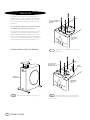
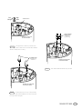
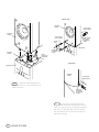
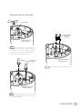
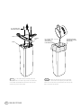
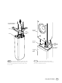
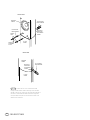
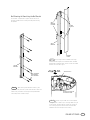
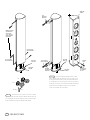
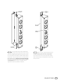
PRELUDE MTS TOWER
™
Owner’s Guide
PRELUDE MTS TOWER OWNER’S GUIDE
Table of Contents
2
PRELUDE MTS TOWER
3
Technology – Ceramic Metal Matrix Diaphragms™ (C.M.M.D.™)
3
Unpacking the Product/Included Accessories
4
Installing the Tower on Top of the Subwoofer
7
Installing the Tower onto the Floor Stand
11
Wall-Mounting the Tower Using the Wall Bracket
14
Placement
15
Specifications
Infinity Prelude MTS
Completing the Experience
This loudspeaker system represents a refinement of the
principles that have guided Infinity’s loudspeaker designs for
more than 30 years. Loudspeaker development is generally an
evolutionary process. New models usually perform slightly better
than the ones they replace. Over time, the subtle improvements
add up and, when the latest model is compared to a loudspeaker
that is ten or twelve years old, the disparity is unmistakable.
The technology and performance that make the Infinity
Prelude MTS loudspeakers ideal for music listening also make
them the perfect digital multichannel loudspeaker system.To
complete a home-theater system, Infinity has designed, to the
same precise standards as the Prelude MTS, a matching 3-way
center-channel loudspeaker. Also, additional Prelude MTS Towers
are available separately for use as full-range surround channels.
The towers can be either wall mounted or attached to matching
stands for floor placement.
Every once in a while, a loudspeaker is developed that
transcends this pattern – its performance so remarkable, its
design so stunning, its technology so advanced, it can truly be
described as revolutionary.The new Infinity Prelude MTS
loudspeaker system is an elegant case in point.
TECHNOLOGY
We hope you enjoyed this brief introduction to the technology of
the Prelude MTS system. If you would like to further explore the
technology and design of the Prelude MTS system, please ask
your Infinity dealer for the C.M.M.D. White Paper.The White
Paper can also be downloaded from Infinity’s Web site at
www.infinitysystems.com.
Unpacking the Product
As part of the Prelude MTS system, the Prelude MTS Tower
incorporates several innovative technologies that, when
implemented by exceptional engineering talent after hours upon
hours of subjective listening evaluations, result in a loudspeaker
that realistically and accurately reproduces the signal source with
minimal distortion and coloration.
Ceramic Metal Matrix Diaphragms™ (C.M.M.D.)
For decades, loudspeaker engineers have known that the ideal
transducer should be stiff, yet light, and have high internal
damping. (Damping is a material’s ability to absorb energy.)
Infinity’s C.M.M.D. transducer is a significant advance in
transducer technology. Ceramic, a class of material new to
loudspeakers, offers better performance than that of other
materials. Ceramic is stiffer than metals and lighter than plastics
and typical composite materials; it also offers improved damping.
These ceramic-based transducers take us a giant step closer to
the ever-elusive “ideal transducer.”
Unpack the speakers and check the contents. If you suspect
damage from transit, report it immediately to your dealer and/or
delivery service. Keep the shipping carton and packing materials
for future use.
Included Accessories . . .
PRELUDE MTS TOWER
Screw Caps (2)
10-32 Socket
Head Srews (4)
In tweeters, C.M.M.D. technology offers stiffness and damping
superior to that of traditional metals and soft-dome materials.
In woofer and midrange applications, it offers accurate pistonic
operation over the entire frequency range of the driver,
completely eliminating coloration due to cone breakup and
dramatically reducing distortion. And when ceramic-metal-matrix
transducers are exposed to moisture, sunlight or extreme
temperatures, their performance does not deteriorate.
Transducers
In addition to ceramic diaphragms, all the transducers
incorporate magnetic shielding and rigid cast-frames that,
through our FEA computer modeling and scanning-laservibrometer measurements, have been optimized to reduce
resonances.This ensures minimal distortion and incomparable
performance.
PRELUDE MTS TOWER
3
INSTALLATION
Please read through this owner’s guide completely before
attempting to install or connect the speakers. We understand that
you may be anxious to play your new system, so we have made
every effort to simplify the installation and connections of the
Prelude MTS.
(4) 10-32 FLAT HEAD
PHILLIPS MACHINE
SCREWS
Please see the guide included with the Prelude MTS Subwoofer
for complete placement and connection instructions.
Before proceeding, you should decide how you would like to install
the tower portion of the Prelude MTS system.The tower may be
attached to the powered subwoofer, mounted to our optional floor
stands, or mounted on the wall using the optional wall brackets. In
all cases, it is strongly recommended that two or three people help
install the tower to minimize the possibility of damage or injury.
Installing the Tower on Top of the Subwoofer
SUBWOOFER
TOP-FRONT
VIEW
STEP 2
– Remove the four machine, 10-32 Phillips flat head
screws from subwoofer cup.
CAP
(4) 10-32 BUTTON
HEAD PHILLIPS
MACHINE SCREWS
METAL
BRACKET
PRELUDE
SUBWOOFER
SUBWOOFER
TOP-FRONT
VIEW
STEP 1 – Remove cap from subwoofer by gently lifting it off.
4
PRELUDE MTS TOWER
STEP 3 – Add metal bracket, positioning as shown; replace
the four existing screws with four machine, 10-32 Phillips head
screws provided.
High
Pass
TOGGLE SWITCH
High
Full
Range Pass
Full
Range
DOUBLE-ENDED
BANANA PLUG
WITH
( INCLUDED
SUBWOOFER )
VIEWING CUP IN BOTTOM
OF SPEAKER TOWER
High
Full
Range Pass
STEP 4 – Set Toggle Switch in tower cup in bottom to the
“Full Range” position. Please consult the Prelude MTS Subwoofer
manual for exceptions to this setting.
ALIGNMENT PINS
WITH
( INCLUDED
SUBWOOFER )
VIEWING CUP IN BOTTOM
OF SPEAKER TOWER
STEP 6
– Insert double-ended Audio Banana Plug into tower
High
Full
Range Pass
as shown.
VIEWING CUP IN BOTTOM
OF SPEAKER TOWER
STEP 5 – Screw alignment pins into cup in bottom of tower,
using two per tower. Screw threaded ends into holes and tighten
until snug. DO NOT overtighten.
PRELUDE MTS TOWER
5
FRONT VIEW
SPEAKER
TOWER
10-32 SOCKET
HEAD SCREWS
SPEAKER
TOWER
10-32 SOCKET
HEAD SCREWS
REAR SLOT
IN BOTTOM
OF SPEAKER
TOWER
SCREW
CAPS
SUBWOOFER
BRACKET
GUIDES
SCREW-CAP
ALIGNMENT
SLOTS
GUIDE
HOLES FOR
ALIGNMENT
PINS
REAR VIEW
SUBWOOFER
SPEAKER
TOWER
10-32 SOCKET
HEAD SCREWS
STEP 7 – Slowly lower the tower assembly onto the
subwoofer, being careful to insert the alignment pins into
receptacle guide holes.
REAR SLOT
IN BOTTOM
OF SPEAKER
TOWER
STEP 8 – Fasten the four 10-32 Socket Head Screws
through the tower base as shown: two through the front baffle
and two in the rear slot. Press flush into place two screw caps to
hide holes in front baffle base. Make sure that the alignment
slots point toward the center to assure that the surface curve
matches that of the baffle.
6
PRELUDE MTS TOWER
Installing the Tower onto the Floor Stand
High
Pass
TOGGLE SWITCH
High
Pass
Full
Range
Full
Range
DOUBLE-ENDED
BANANA PLUG
WITH
( INCLUDED
)
STAND
VIEWING CUP IN BOTTOM
OF SPEAKER TOWER
Full
Range
High
Pass
STEP 1 – When using the tower as a surround speaker,
set Toggle Switch in tower cup to “Full Range.” When using as
a front channel, set Toggle Switch in tower cup in bottom to
the “Full Range” position. Please consult the Prelude MTS
Subwoofer manual for exceptions to this setting.
VIEWING CUP IN BOTTOM
OF SPEAKER TOWER
ALIGNMENT PINS
(
INCLUDED WITH
STAND
)
STEP 3 – Insert double-ended Audio Banana Plug into tower
Full
Range
High
Pass
as shown.
VIEWING CUP IN BOTTOM
OF SPEAKER TOWER
STEP 2 – Screw alignment pins into cup in bottom of tower.
Use two per tower. Screw threaded ends into holes and tighten
until snug. DO NOT overtighten.
PRELUDE MTS TOWER
7
(3) 1/4-20 PHILLIPS
MACHINE SCREWS
FOOT
PLASTIC
BAG
BASE
STEP 4 – To add greater stability to the tower stand, add
sand (not included) in the plastic bag provided in the tower base.
Turn the base upside-down and remove the (3) 1/4-20 Phillips
screws holding the foot onto the base.
8
PRELUDE MTS TOWER
FILL PLASTIC BAG
WITH SAND
(NOT INCLUDED)
FOR ADDED WEIGHT
FOLD PLASTIC BAG
OVER SIDES TO KEEP
BASE CLEAN
STEP 5 – Remove one foam pad, and then pull out the plastic
bag and open it. Place it back into the opening of the base, taking
care to fold it over the sides so as to keep sand from falling into the
base. Fill the plastic bag with sand.
(3) 1/4-20 PHILLIPS
MACHINE SCREWS
FOOT
SPEAKER
TOWER
BASE
SEAL
PLASTIC
BAG
BRACKET
GUIDES
GUIDE
HOLES FOR
ALIGNMENT
PINS
1/4-20 CAP
SCREWS
SPEAKER
TOWER
BASE
STEP 6 – Seal the plastic bag, making sure to tuck it back
inside the base, and place the previously removed foam pad on
top of the sealed bag. Replace the foot with the same 1/4-20
Phillips screws.
STEP 7 – Turn stand over and slowly lower the tower
assembly onto the stand, being careful to insert the alignment
pins into their receptacle guide holes.
PRELUDE MTS TOWER
9
FRONT VIEW
SPEAKER
TOWER
10-32 SOCKET
HEAD SCREWS
10-32 SOCKET
HEAD SCREWS
REAR SLOT
IN BOTTOM
OF SPEAKER
TOWER
SCREW
CAPS
SCREW-CAP
ALIGNMENT
SLOTS
FLOOR
STAND
REAR VIEW
SPEAKER
TOWER
REAR SLOT
IN BOTTOM
OF SPEAKER
TOWER
10-32 SOCKET
HEAD SCREWS
FLOOR
STAND
STEP 8 – Fasten the four 10-32 Socket Head Screws
through the tower base as shown: two through the front baffle
and two in the rear slot. Press flush into place two screw caps to
hide holes in front-baffle base. Make sure that the alignment
slots point toward the center to ensure that the surface curve
matches that of the baffle.
10
PRELUDE MTS TOWER
Wall-Mounting the Tower Using the Wall Bracket
The customer is responsible for proper selection and use of
mounting hardware and for correctly and safely wall-mounting
the speakers.
WALL
BRACKET
FLANGES
FLANGE
CUTOUTS
WALL
BRACKET
BRACKET
COVER
STEP 2 – Align Flange Cutouts in Bracket Cover flange
with Wall Bracket flanges, and slide Bracket Cover onto Wall
Bracket. Now slide Bracket Cover so that it centers on the Wall
Bracket.This should be a tight fit.
WALL
BRACKET
Full
Range
High
Pass
TOGGLE SWITCH
STEP 1 – When mounting each bracket to the wall, try and
position it so that you anchor it to wall studs. Be sure to anchor the
bracket firmly to the wall to sufficiently hold the Speaker Tower.
Use screw positions as shown in Step1.
Full High
Range Pass
WALL ANCHORS
AND SCREWS
NOT PROVIDED
VIEWING CUP IN BOTTOM
OF SPEAKER TOWER
STEP 3 – When using the tower as a surround speaker,
set Toggle Switch in tower cup to “Full Range.” When using as
a front channel, set Toggle Switch in tower cup in bottom to
the “Full Range” position. Please consult the Prelude MTS
Subwoofer manual for exceptions to this setting.
PRELUDE MTS TOWER
11
SPEAKER
TOWER
TOP
SPEAKER
BRACKET
REMOVE SHORT
AND REPLACE
WITH LONG
10-32 SOCKET
HEAD SCREWS
PROVIDED
10-32 SOCKET
HEAD SCREWS
10-32 SOCKET
HEAD SCREWS
BOTTOM
END CAP
SPEAKER
SPEAKER
CABLES
CABLES
RED =
BLACK =
–
+
STRIPE =
+
STEP 4 – Remove (2) existing screws in top and (4) in bottom
of Speaker Tower as shown. Feed your speaker cables through the
slot in the Bottom End Cap as shown and connect to the terminals.
Place the Bottom End Cap on the Speaker Tower bottom.
12
BOTTOM
SPEAKER
BRACKET
SPEAKER
SPEAKER
CABLES
CABLES
STEP 5 – Place Top and Bottom Speaker Holders in back
slots of Speaker Tower top and bottom. Insert (2) longer 10-32
Socket Head Screws provided in each and tighten. Replace the
(2) screws taken out of the front baffle. Press flush into place 2
screw caps to hide holes in front-baffle base. Make sure that the
alignment slots point toward the center to ensure that the
surface curve matches that of the baffle.
–
NO STRIPE =
BOTTOM
END CAP
10-32 SOCKET
HEAD SCREWS
PRELUDE MTS TOWER
SCREW
CAPS
SCREW-CAP
ALIGNMENT
SLOTS
5/16-24 HEX
HEAD BOLT
WALL
BRACKET
CAPS
WALL
BRACKET
TOWER
SPEAKER
5/16-24 HEX
HEAD BOLT
STEP 6 – To mount Speaker Tower assembly to Wall Bracket
assembly, lift the Speaker Tower assembly, with the help of another
person, onto the Wall Bracket assembly. Have one person continue
to hold the Speaker Tower assembly on the Wall Bracket assembly
while the other inserts and tightens one of (2) 5/16-24 Hex Head
Bolts provided into the top. Make sure you insert and finger-tighten
the top one first to keep the Speaker Tower assembly from slipping
off the Wall Bracket. After the top bolt is tightened, insert and
tighten the other 5/16-24 Hex Head Bolt in the bottom.
WALL
BRACKET
CAPS
STEP 7 – Note: If you wish to angle the Speaker Tower into
a permanent position, you will need to do so and tighten the
5/16-24 Hex Head Bolts before you attach the Wall Bracket
Caps.Tighten both bolts securely and attach the Wall Bracket
Caps to the top and bottom of the Wall Bracket.These will snap
securely into place.
PRELUDE MTS TOWER
13
PLACEMENT
FIGURE 1
RIGHT
CHANNEL
LEFT
CHANNEL
2-Channel or Front-Left and Front-Right
Speakers in a Home-Theater System
SOFA
FIGURE 2
LEFT
FRONT
RIGHT
FRONT
TV
When used as part of a home-theater system, you may find that
you achieve excellent performance with the left and right
speakers spread apart even further. Feel free to experiment with
the placement of the speakers to achieve the best possible sound
in your listening room.
Normally, it is recommended that the driver of each subwoofer
face toward the outside, and this is how the subs are packaged.
For some rooms, however, the system may perform better with the
woofers facing the inside. Feel free to experiment.
➢
➢
Generally, the system should be placed with the tower section
installed atop the subwoofer, at least three feet away from the
side walls. In 2-channel applications, the two speakers should be
equidistant from your primary listening position. We recommend
that the angle formed between the speakers and the listening
area be between 45° and 60.° For example, if the speakers are
8' apart, your listening position should be 8' to 12' from
each speaker. See Figure 1. With wider speaker separations, it
may be advantageous to slightly angle the speakers, aiming them
toward the listening area.
➢
➢
The Infinity Prelude MTS is designed to offer excellent
performance in any listening room or home-theater system.
However, the following placement guidelines and suggestions
will start you on your way to achieving optimum performance.
Remember, these are guidelines. We suggest you experiment with
positioning the loudspeakers to determine their ideal placement
in your particular listening room.
CENTER
LEFT
SURROUND
RIGHT
SURROUND
SOFA
Surround Channels in a Home-Theater System
FIGURE 3
LEFT
FRONT
RIGHT
FRONT
TV
CENTER
SOFA
➢
LEFT
SIDE
LEFT
REAR
14
PRELUDE MTS TOWER
➢
➢
When used as part of a 7-channel music or home-theater system,
place the side speakers at the sides of and directed toward the
main listening area. If there are several rows of seating, place
the speakers, as described above, perpendicular to the middle
row of seating.The rear speakers should be placed on the rear
wall facing the front of the room. Each rear speaker should be
about 1/3 of the way into the room, but never to the outside of
the listening area. See Figure 3.
RIGHT
SIDE
➢
When used as part of a Dolby* Pro Logic*,THX®, or discrete 5.1
channel home-theater system, the surround speakers should be
placed at the sides of, and directed toward, the main listening
area. See Figure 2. If there are several rows of seating, place the
speakers, as described above, perpendicular to, or slightly
behind, the last row of seating.
RIGHT
REAR
SPECIFICATIONS
Prelude MTS Tower
Optional Accessories:
Frequency Response:
80Hz – 22kHz (±3dB)
100Hz – 20kHz (±1.5dB)
Impedance:
4Ω (±1Ω)
Sensitivity:
90dB
Prelude MTS-WB: Wall Bracket for Tower
Prelude MTS-FS: Floor Stand for Tower
(2.83V @ 1 meter)
Recommended
Amplifier Power Range:
25 – 500 watts
2nd- and 3rd-Order
Harmonic Distortion:
<1%
(20Hz – 20kHz @ 95dB SPL)
Crossover Frequencies:
80Hz, 300Hz, 2kHz
24dB/Octave
Dimensions:
37" x 6-1/2" x 7-1/2"
(940mm x 165mm x 191mm)
Declaration of Conformity
We, Infinity Europe A/S
Kongevejen 194B
DK-3460 Birkerød
DENMARK
declare in own responsibility, that the product described
in this owner’s manual is in compliance with technical
standards:
EN 50081-1:1992
EN 50082-1:1992
Infinity continually strives to update and improve existing products, as well as create
new ones.The specifications and construction details in this and related Infinity
publications are therefore subject to change without notice.
Steen Michaelsen
Infinity Europe A/S
Birkerød. DENMARK. 10/99
PRELUDE MTS TOWER
15
© 1999 Infinity Systems, Inc., 250 Crossways Park Drive, Woodbury, NY 11797 USA (800) 553-3332 (USA Only) www.infinitysystems.com
*Trademarks of Dolby Laboratories.THX is a registered trademark of Lucasfilm, Ltd.
Infinity is a registered trademark of Infinity Systems, Inc. Printed in USA 10/99 Part
No. 335060-002