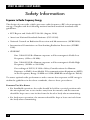
1
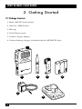
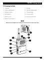
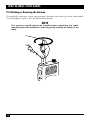
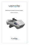
MU22CV
MU22CVS
MV11C
MV24CVS
MV24CVST
MAY 1998
HTN9025
HMN9038
HLN9897
HLN9898
Spirit M-Series 2-Way Radios
MIC
IT
SPIR
LA
ORO
MOT
CUSTOMER
SUPPORT
INFORMATION
Order toll-free in the U.S.: Call 877-877-BBOX (outside U.S. call 724-746-5500)
FREE technical support 24 hours a day, 7 days a week: Call 724-746-5500 or fax 724-746-0746
Mailing address: Black Box Corporation, 1000 Park Drive, Lawrence, PA 15055-1018
Web site: www.blackbox.com • E-mail: [email protected]
TRADEMARKS/COPYRIGHT INFORMATION
TRADEMARKS USED IN THIS MANUAL
Motorola is a registered trademark of Motorola.
Any other trademarks mentioned in this manual are acknowledged to be the
property of the trademark owners.
Copyright Information
The Motorola® products described in this manual may include copyrighted
Motorola programs stored in semiconductor memories or other media. Laws in the
United States and other countries preserve for Motorola, certain exclusive rights
for copyrighted computer programs, including the exclusive right to copy or
reproduce in any form, the copyrighted Motorola programs. Accordingly, any
copyrighted Motorola computer programs contained in the Motorola products
described in this manual may not be copied or reproduced in any manner without
the express written permission of Motorola. Furthermore, the purchase of
Motorola products shall not be deemed to grant either directly or by implication,
estoppel, or otherwise, any license under the copyrights, patents, or patent
applications of Motorola, except for the normal non-exclusive royalty-free license
to use that arises by operation of law in the sale of a product.
1
SPIRIT M-SERIES 2-WAY RADIOS
Contents
Chapter
Page
1. Specifications ............................................................................................................8
2. Getting Started ........................................................................................................10
2.1 Package Contents ........................................................................................10
2.2 Examining the Radio ..................................................................................11
2.3 Attaching or Removing the Antenna ........................................................12
2.4 Attaching or Removing the Belt Clip ........................................................13
2.5 Ni-Cad Batteries ..........................................................................................14
2.6 Low-Battery Alert ........................................................................................14
2.7 Installing and Removing Batteries ............................................................15
2.8 Charging the Battery with the Charger Adapter ......................................16
2.9 Charging the Battery with the 10-Hour Desktop Charger ......................18
3. Programming ..........................................................................................................20
3.1 Understanding Frequencies and Codes ....................................................20
3.1.1 Frequencies ....................................................................................20
3.1.2 Interference Eliminator Codes......................................................20
3.2 To Change Frequency and Code Settings ................................................21
3.2.1 1-Channel Models ..........................................................................21
3.2.2 2- and 4-Channel Models................................................................22
4. Operation ................................................................................................................24
4.1 Turning the Radio On or Off ....................................................................24
4.2 Adjust the Volume ......................................................................................24
4.3 Sending or Receiving Messages..................................................................24
4.4 Time-Out Timer ..........................................................................................24
4.5 Scan ..............................................................................................................25
4.6 Built-In VOX ................................................................................................26
5. Troubleshooting ......................................................................................................27
5.1 Radio Care ..................................................................................................28
5.2 Talk Range ..................................................................................................28
Appendix: Frequency and Code Tables ....................................................................29
2
FCC INFORMATION/NI-CAD BATTERY RECYCLING
FCC Licensing Information
Your radio operates on FM radio communication frequencies and is subject to the
Rules and Regulations of the Federal Communications Commission (FCC). The
FCC requires that all operators using Private Land Mobile frequencies obtain a
radio license before operating their equipment. Application for your FCC license is
made on FCC Form 600 and schedules D, E, and G.
To have the forms faxed to you by the FCC, call the FCC Fax-On-Demand system at
1-202-418-0177 from your fax machine and request document 000600 for all forms
and instructions.
To have the forms mailed to you, call the FCC forms hotline at 1-800-418-3676. For
questions concerning the license application, contact the FCC at 1-888-225-5322.
Before filling out your application, you must decide which frequency or
frequencies you can operate on. See the frequency tables in the Appendix.
For questions on determining your radio frequency, call Technical Support.
Recycling of Nickel-Cadmium Batteries
Nickel-cadmium (Ni-Cad) rechargeable batteries can be recycled. However,
recycling facilities may not be available in all areas. Under various U.S. state laws,
Ni-Cad batteries must be recycled or disposed of properly and cannot be disposed
of in landfills or incinerators.
Many retailers participate in the nation-wide Rechargeable Battery Recycling
Corporation (RBRC) program for nickel-cadmium battery collection and
recycling. For the name of the retailer nearest your location, call 1-800-8BATTERY. This number also provides access to other useful information for
consumers, businesses, and governmental agencies concerning recycling options.
3
SPIRIT M-SERIES 2-WAY RADIOS
Safety Information
Exposure to Radio Frequency Energy
The design of your radio, which generates radio frequency (RF) electromagnetic
energy, complies with the following national and international standards and
guidelines.
• FCC Report and Order FCC 96-326 (August, 1996)
• American National Standards Institute (C95-1-1992)
• National Council on Radiation Protection and Measurements (NCRP-1986)
• International Commission on Non-Ionizing Radiation Protection (ICNRP1986)
• CENELEC
Env. 50166-11995E—Human exposure to Electromagnetic Fields Low
Frequency (0 Hz to 10 kHz)
Env. 50166-21995E—Human exposure to Electromagnetic Fields High
Frequency (10 kHz to 300 GHz)
Proceedings of SC211/8 1996—Safety Considerations for Human
Exposure to EME’s from Mobile Telecommunications Equipment (MTE)
in the Frequency Range 30 MHz to 6 GHz (EME-Electromagnetic Fields).
To assure optimal radio performance and to ensure that exposure to RF energy is
within the guidelines in the above standards, observe these procedures:
PORTABLE TWO-WAY RADIOS
• For handheld operation, the radio should be held in a vertical position with
the microphone one to two inches away from the mouth, and the antenna
should be kept one to two inches from the head or body when transmitting.
• For body-worn operation, the antenna should be kept at least one inch from
the body when transmitting.
4
SAFETY INFORMATION
VEHICLE-INSTALLED MOBILE TWO-WAY RADIOS
• Properly install antennas externally on the vehicle, following recommended
installation procedures.
• Transmit only when people inside or outside the vehicle are at least 1 to 3 feet
away from the properly installed, externally mounted antenna; distance
guidelines for the different power levels are summarized in the table below:
Rated power of
vehicle-mounted radio
Min. distance of people
from transmitting antenna
7 to 15 watts
16 to 50 watts
more than 50 watts
1 foot
2 feet
3 feet
Electromagnetic Interference/Compatibility
Nearly every electronic device is susceptible to electromagnetic interference (EMI)
if inadequately shielded, designed, or otherwise configured for electromagnetic
compatibility.
• Turn your radio off in any facilities where posted notices instruct you to do so.
Hospitals or health-care facilities may be using equipment that could be
sensitive to external RF energy.
• Turn your radio off when on board aircraft when instructed to do so. Any use
of the radio must be in accordance with airline regulations or crew
instructions.
WARNING!
Potentially explosive atmospheres:
Turn your radio off when in any area with a potentially explosive
atmosphere. Sparks in such areas could cause an explosion or fire
resulting in bodily injury or even death.
Do not replace or charge batteries in a hazardous atmosphere. Contact
sparking may occur while installing or removing batteries and cause an
explosion.
Areas with potentially explosive atmospheres are often, but not always,
clearly marked. They include fueling areas such as below deck on boats,
fuel or chemical transfer or storage facilities; areas where the air
contains chemicals or particles, such as grain, dust, or metal powders;
and any other area where you would normally be advised to turn off
your vehicle engine.
5
SPIRIT M-SERIES 2-WAY RADIOS
Blasting caps and areas:
To avoid possible interference with blasting operations, turn your radio
off near electrical blasting caps or in a “blasting area” or in areas
posted: “Turn off two-way radio.” Obey all signs and instructions.
For vehicles with an air bag:
An air bag inflates with great force. Do not place objects, including
portable or mobile two-way radios, in the area over the air bag or in the
air bag deployment area. If improperly installed or placed wireless
equipment is in the air bag deployment area and the air bag inflates,
serious injury could result.
CAUTION
Antennas:
Do not use a radio with a damaged antenna. If a damaged antenna
comes into contact with the skin, a minor burn may result.
Batteries:
All batteries can cause property damage, injury, or burns if a conductive
material such as jewelry, keys or beaded chains touches exposed
terminals. The material may complete an electrical circuit (short circuit)
and become quite hot. Exercise care in handling any charged battery,
particularly when placing it inside a pocket, purse or other container
with metal objects.
Chargers and power cord:
To reduce the risk of damage to electric plug and cord, pull by the plug
rather than the cord when disconnecting the charger.
Make sure the cord is located so that it will not be stepped on, tripped
over, or otherwise subjected to damage or stress.
Do not operate the charger with a damaged cord or plug; replace them
immediately. Do not operate charger if it has received a sharp blow,
been dropped, or otherwise been damaged in any way.
Do not expose chargers to rain or snow.
6
SAFETY INFORMATION
An extension cord should not be used unless absolutely necessary. Use
of an improper extension cord may result in a fire or electric shock.
However, if an extension cord must be used, make sure:
• that pins and plug of extension cord are the same number, size, and
shape as those on the plug of the charger.
• that the extension cord is properly wired and in good condition.
• the cord size is 18 AWG for lengths of up to 100 feet, and 16 AWG for
lengths up to 150 feet.
• that you do not disassemble the charger. Incorrect reassembly can
result in electric shock or fire.
• to reduce the risk of injury by charging only Motorola Ni-Cad
rechargeable batteries. Other types of batteries may burst, causing
personal injury and damage.
• to unplug the charger from the outlet before cleaning. This reduces the
risk of electric shock. Turning off controls does NOT reduce this risk.
Use of attachments other than those mentioned in this guide can result
in a risk of fire, electric shock, or injury to personnel.
7
SPIRIT M-SERIES 2-WAY RADIOS
1. Specifications
Range —
MV11C: In buildings, up to 150,000 square feet
(13,935 square m) or 8 floors. Outdoors, up to
4 miles (6.4 km) in flat, open areas with no
obstructions, or up to 2 miles (3.2 km) around
residential buildings. MU22CV, MU22CVS: In
buildings, up to 250,000 square feet
(23,225 square m) or 20 floors. Outdoors, up to
5 miles (8 km) in flat, open areas with no
obstructions, or up to 2 miles (3.2 km) around
residential buildings. MV24CVS, MV24CVST: In
buildings, up to 180,000 square feet (16,722
square m) or 10 floors. Outdoors, up to 5 miles
(8 km) in flat, open areas with no obstructions,
or up to 2.5 miles (4 km) around residential
buildings. (Note: Range is reduced around hills
or dense foliage.)
Band —
MU22CV, MU22CVS: UHF; MV11C, MV24CVS,
MV24CVST: VHF
Interference Protection —
An Interference Eliminator is standard on all
radio models
Channel Spacing —
25 kHz
Channels —
MV11C: 1; MU22CV, MU22CVS: 2; MV24CVS,
MV24CVST: 4
Selectable Frequencies —
MU22CV, MU22CVS: 464.500 MHz (Brown),
464.550 MHz (Yellow), 467.7625 MHz (J),
467.8125 MHz (K), 467.850 MHz (Silver star),
467.875 MHz (Gold star), 467.900 MHz (Red
star), 467.925 MHz (Blue star); MV24CVS,
MV24CVST, and MV11C: 151.6250 (Red),
151.9550 (Purple), 154.5700 (Blue), 154.6000
(Green)
Accessory Jack —
For use with charger adapter and all audio
accessories
Power Supply —
Rechargeable Ni-Cd battery
8
CHAPTER 1: Specifications
Battery Life —
MV11C: Up to 10 hours per battery charge; All
other radio models: Up to 8 hours per battery
charge; All models: 1- to 2-year life with normal
use
Power Output —
MV11C: 1 watt; All other radio models: 2 watts
Size —
4.5"H x 2.5"W x 1.2"D (11.4 x 6.4 x 3 cm);
Height with antenna: 10" (25.4 cm) for
MV24CVS, MV24CVST, and MV11C; 8" (20.3
cm) for MU22CV, MU22CVS
Weight —
0.7 lb. (0.3 kg)
9
SPIRIT M-SERIES 2-WAY RADIOS
2. Getting Started
2.1 Package Contents
1. Radio (MV11C shown below)
2. Antenna (UHF shown)
3. Belt clip
4. Ni-Cad battery pack
5. 10-hour charger adapter
6. 10-hour desktop charger (included with the MV24CVST only)
PU
SH
TO
TAL
K
MIC
IT
SPIR
LA
ORO
MOT
1
MOTOROLA
NIT
OR
MOTOROLA
MO
2
3
4
5
G
RGIN
CHA
LA
ORO
MOT
6
10
CHAPTER 2: Getting Started
2.2 Examining the Radio
1. Antenna
7.
Speaker
2. Push-to-talk button
8.
On-Off/volume knob
3. Monitor button
9.
Transmit light
4. Microphone
10. Accessory jack
5. Battery cover
11. Accessory jack cover
6. Battery cover latches
NOTE
Multi-channel models have a channel selector knob on top of the radio.
MIC
SPI
RIT
11
MOTOROLA
10
1
9
8
2
7
PU
SH
TO
TAL
K
3
MO
NIT
OR
MIC
IT
SPIR
4
5
LA
ORO
MOT
6
6
11
SPIRIT M-SERIES 2-WAY RADIOS
2.3 Attaching or Removing the Antenna
To attach the antenna, rotate the antenna clockwise onto the top of the radio until
it’s held tightly in place. See the illustration below.
NOTE
MOTOR
The antenna should always be installed when operating the radio.
Operating the radio without an antenna greatly reduces the range of the
radio.
PU
SH
TO
TAL
K
MO
NIT
OR
12
MIC
CHAPTER 2: Getting Started
2.4 Attaching or Removing the Belt Clip
1. Align the belt clip to the mounting rails on the back of the radio (see the first
illustration below).
2. Push the belt clip down until it clicks into place.
3. To remove the belt clip, pull the tab on the belt clip away from the radio to
release (see the second illustration below).
MOTOROLA
4. Slide the belt clip up and off.
A
C
C
ROLA
MOTOROLA
A
C
C
E
S
S
13
SPIRIT M-SERIES 2-WAY RADIOS
2.5 Ni-Cad Batteries
Since the Ni-Cad battery ships uncharged, it must be fully charged for 16 hours
before use (for the first charge only). We recommend using only Motorola
batteries and chargers with the radio.
The Ni-Cad rechargeable battery pack will provide approximately 8 hours of
operation for a 2-watt radio and 10 hours of operation for a 1-watt radio with
normal use (5% sending messages, 5% receiving messages, and 90% in standby
mode).
2.6 Low-Battery Alert
When the battery is low, the radio will beep:
• 3 to 4 seconds after turning power on,
• every 10 minutes in standby mode, and
• after release of the push-to-talk button.
Recharge the battery pack immediately to avoid interrupted use.
NOTE
Remove the battery pack before storing your radio for extended periods.
Batteries may corrode over time if left in the radio and can cause
permanent damage to your radio.
14
CHAPTER 2: Getting Started
2.7 Installing and Removing Batteries
NOTE
The radio must be off before installing or removing the battery.
1. Push back both battery cover latches until you see the orange tabs.
2. Slide the battery cover down and lift to remove (see the first illustration
below). To replace or install the battery, insert the battery pack with the arrows
pointing toward the top of the radio (see the second illustration below).
15
SPIRIT M-SERIES 2-WAY RADIOS
3. Replace the battery cover and lock latches.
4. To remove the battery, first remove the cover. Turn the radio over and tap the
battery end of the radio against the palm of your hand. The battery will drop
into your hand (see the illustration below).
NOTE
Do not remove the plastic wrap from the battery pack. This will
permanently damage the battery.
2.8 Charging the Battery with the Charger Adapter
NOTES
To reduce the risk of injury, charge only Motorola nickel-cadmium
rechargeable battery packs. Other types of batteries can burst, causing
personal injury and damage.
For optimum battery life, the battery should not be left charging for
prolonged periods after reaching full charge. Charging the battery over
the weekend is acceptable.
Do not transmit while the radio is charging. Transmitting while the radio
is charging can cause the radio transmitter or the charger to operate
improperly.
Turn the radio off when it’s charging. If the radio is on while it’s
charging, at least twice as much time is required to charge the battery.
16
CHAPTER 2: Getting Started
WARNING!
Do not expose chargers to rain or snow.
Use of a non-Motorola attachment can result in a risk of fire, electric
shock, or personal injury.
To reduce the risk of damage to the electric plug and cord, pull the plug
rather than the cord when disconnecting the charger.
Make sure the cord is located so that it will not be stepped on, tripped
over, or otherwise subjected to damage or stress.
An extension cord should not be used unless absolutely necessary. Use
of an improper extension cord could result in a fire or electric shock.
However, if an extension cord must be used, make sure that a) the pins
and the plug of the extension cord are the same number, size, and
shape as those on the plug of the charger, b) the extension cord is
properly wired and in good condition, and c) the cord size is 18 AWG for
lengths up to 100 feet and 16 AWG for lengths up to 150 feet.
Do not operate the charger with a damaged cord or plug. Do not operate
the charger if it has received a sharp blow, been dropped, or otherwise
been damaged in any way.
Do not disassemble the charger. Incorrect reassembly can result in
electric shock or fire. Call Black Box if it needs to be repaired.
To reduce the risk of electric shock, unplug the charger from the outlet
before attempting any maintenance or cleaning. Turning off controls
does not reduce this risk.
1. Turn the radio off.
2. Lift the accessory cover and plug the charger adapter firmly into the small jack
(lower hole). See the illustration below.
17
MOTOROLA
SPIRIT M-SERIES 2-WAY RADIOS
MIC
SPIR
IT
3. Plug the charger into an electric outlet. The light on the charger will glow
continuously if charging properly.
4. Allow 10 hours for the battery to fully charge.
2.9 Charging the Battery with the 10-Hour Desktop Charger (included with
the MV24CVST)
WARNING!
Do not expose chargers to rain or snow.
Use of a non-Motorola attachment can result in a risk of fire, electric
shock, or personal injury.
To reduce the risk of damage to the electric plug and cord, pull the plug
rather than the cord when disconnecting the charger.
Make sure the cord is located so that it will not be stepped on, tripped
over, or otherwise subjected to damage or stress.
An extension cord should not be used unless absolutely necessary. Use
of an improper extension cord could result in a fire or electric shock.
However, if an extension cord must be used, make sure that a) the pins
and the plug of the extension cord are the same number, size, and
shape as those on the plug of the charger, b) the extension cord is
properly wired and in good condition, and c) the cord size is 18 AWG for
lengths up to 100 feet and 16 AWG for lengths up to 150 feet.
Do not operate the charger with a damaged cord or plug. Do not operate
the charger if it has received a sharp blow, been dropped, or otherwise
been damaged in any way.
18
CHAPTER 2: Getting Started
Do not disassemble the charger. Incorrect reassembly can result in
electric shock or fire. Call Black Box if it needs to be repaired.
To reduce the risk of electric shock, unplug the charger from the outlet
before attempting any maintenance or cleaning. Turning off controls
does not reduce this risk.
To reduce the risk of injury, charge only Motorola nickel-cadmium
rechargeable battery packs. Other types of batteries can burst, causing
personal injury and damage.
1. Connect the desktop charger and charger adapter (see the illustration below).
2. Charge the battery while inside the radio by placing the radio in the desktop
charger with the radio facing toward you.
You can also charge the battery by removing the battery from the radio and
placing it in the desktop charger. The silver contacts must face down, and the
arrow must point toward the front of the charger.
3. The light on top of the desktop charger will glow continuously when the radio
(or battery) is inserted. If the light does not come on, make sure the radio (or
battery) is properly inserted and check the battery/charger contacts to be sure
they are clean. The light will continue to glow until the radio (or battery) is
removed from the desktop charger.
4. Allow 10 hours for the battery to fully charge.
19
SPIRIT M-SERIES 2-WAY RADIOS
3. Programming
3.1 Understanding Frequencies and Codes
3.1.1 FREQUENCIES
Your radio operates on group of frequencies (see the Appendix for a complete
listing). You access frequency or frequencies through radio channel(s). You can
operate on any of your radio’s frequencies, but each must be licensed through the
FCC (see page 3).
To understand the difference between frequencies and channels, think of
channels as pre-set buttons on your car stereo and the frequencies as the many
radio stations available. You can select and save different stations (frequencies) to
pre-set buttons (channels) for easy access.
3.1.2 INTERFERENCE ELIMINATOR CODES
Codes filter out static, noise, and unwanted chatter on radio channels (see the
Appendix for a complete listing). When you operate on a frequency with a code
set, you block out most interference on the frequency. This allows you to
communicate with less interference than when operating without a code.
Remember, since radio frequencies can be monitored, codes will not make your
conversations private.
NOTE
For compatibility with radios that do not have codes, the radio can be
set to Code “Off” in the programming mode. See the following
instructions.
NOTE
To talk to others in your group, all radios must be set to the same
channel and code.
There are settings programmed into your radio for frequencies and codes. If it is
necessary to confirm settings or to change them for licensing purposes, the radio
will audibly guide you through a series of programming steps.
20
CHAPTER 3: Programming
3.2 To Change Frequency and Code Settings
3.2.1 1-CHANNEL MODELS
1. Hold the Push-To-Talk button down while turning the radio on (turning the
On/Off Volume knob at the top of the radio). The radio announces the
current frequency setting. For example, it might say, “Frequency one.”
2. Press the Push-To-Talk button to scroll through frequencies. The radio
announces each frequency as you scroll. For example, it might say,
“Two...three....”
3. Release the Push-To-Talk when you’ve reached the desired frequency.
4. Press the Monitor button to select and save the new frequency setting. The
radio announces the current code setting. For example, it might say, “Code two
nine.”
5. Press the Push-To-Talk button to scroll through the codes. The radio
announces each code as you scroll. For example, it might say, “three
zero...three one...”
6. Release the Push-To-Talk button when you’ve reached the desired code.
7. Press the Monitor button to select and save the new code setting. The radio
beeps to indicate that it has exited programming and is ready for use.
21
SPIRIT M-SERIES 2-WAY RADIOS
3.2.2 2- AND 4-CHANNEL MODELS
MOTOROLA
1. Turn the Channel Selector knob to Channel 1 (see the illustration below).
PU
SH
TO
TAL
K
MO
NIT
OR
MIC
IT
SPIR
2. Hold the Push-To-Talk button down while turning the radio on (turning the
On/Off Volume knob at the top of the radio). The radio announces the
current frequency setting for that channel. For example, it might say,
“Frequency one.”
3. Press the Push-To-Talk button to scroll through the frequencies. The radio
announces each frequency as you scroll. For example, it might say,
“Two...three....”
4. Release the Push-To-Talk when you’ve reached the desired frequency.
5. Turn the Channel Selector knob to channel 2 and repeat steps 3 and 4. For the
4-channel models, repeat to set channels 3 and 4.
6. Press the Monitor button to select and save the new frequency setting. The
radio announces the current code setting. For example, it might say, “Code two
nine.”
7. Press the Push-To-Talk button to scroll through the codes. The radio
announces each code as you scroll. For example, it might say, “three
zero...three one...”
22
CHAPTER 3: Programming
8. Release the Push-To-Talk button when you’ve reached the desired code.
9. Press the Monitor button to select and save the new code setting. The radio
beeps to indicate that it has exited programming and is ready for use.
NOTES
To use this radio with other Motorola radios, see the tables in the
Appendix.
Code numbers with two digits (10-38) will be announced “one zero” to
“three eight.”
You can only scroll forward when selecting frequency or code.
When you are changing frequency or code, you cannot send messages.
The code setting applies to all channels. You cannot select a different
code for each channel.
For radio models with the scan feature: The radio will sound a warning
tone if you accidentally switch to the “s” position while programming. See
Chapter 4 for more information.
23
SPIRIT M-SERIES 2-WAY RADIOS
4. Operation
4.1 Turning the Radio On or Off
Turn the On-Off/Volume knob clockwise. You’ll hear a beep and see the Transmit
Light flash momentarily to indicate the radio is on. To turn the radio off, turn the
On-Off/Volume knob counterclockwise. You will hear a click to indicate the radio
is turned off.
4.2 Adjust the Volume
Hold the Monitor button down to listen to the audio level while rotating the OnOff/Volume knob. Rotate the knob clockwise to increase and counterclockwise to
decrease volume.
4.3 Sending or Receiving Messages
Check the channel activity by pressing the Monitor button. You will hear static if
the channel is clear to use. Do not transmit if someone is talking on the channel.
1. To send messages, press the Push-To-Talk speak into the radio. (To maximize
clarity, hold the radio one to two inches from your mouth.)
2. The Transmit Light will glow continuously when sending messages.
3. To listen for messages, release the Push-To-Talk button.
4.4 Time-Out Timer
The Time-Out Timer feature prevents channel congestion and helps extend
battery life. The radio will sound a warning tone if the Push-To-Talk button is
pressed for 60 continuous seconds and will stop transmitting.
24
CHAPTER 4: Operation
4.5 Scan (Optional)
Some radio models have the Scan feature. Scan allows you to monitor the radio’s
programmed channels and code. When the radio detects someone talking, it stops
scanning and locks in on the active channel. It allows you to listen and talk back
automatically to the person transmitting without having to switch channels.
NOTE
To communicate in scan, your radio must be set to the same frequency
and code as the other radio(s) in your group.
To use the Scan feature:
1. Move the Channel Selector knob to the “s” position. The radio will scan the
radio’s programmed channels and code in sequential order.
2. When the radio detects someone talking, you will hear the message.
3. Press the Push-To-Talk button to talk back on the channel.
In Scan, you will always transmit back to the channel which last sent a message.
NOTE
In scan, after you receive a message, the radio will remain on that
channel for three seconds before returning to scan mode.
If you set the Channel Selector knob to the “s” position (scan mode) and
no activity is detected, you will transmit on channel 1 when you press
the Push-To-Talk button.
25
SPIRIT M-SERIES 2-WAY RADIOS
4.6 Built-In VOX (Optional)
Some radio models have the built-in VOX (Voice Activated Transmission). This
feature allows hands-free operation of your radio. The sound of your voice activates
transmission when the radio is used with a Headset with Swivel Boom Microphone
(part number HMN9038). The headset is sold separately.
To use the VOX feature:
1. Turn the radio off.
2. Open the Accessory jack cover and plug the headset’s connector firmly into
the jack.
3. Turn the radio on and lower the volume before wearing the headset. Press the
monitor button while rotating the Volume knob to adjust the volume to a
comfortable listening level.
4. To transmit, speak into the accessory microphone. To receive, stop talking.
There will be a one-second delay between when you start or stop talking and
radio transmission.
To exit the VOX feature:
1. Press the Push-To-Talk button once.
2. To transmit, press the Push-To-Talk button.
3. To receive messages, release the Push-To-Talk button.
4. To return to VOX mode, turn the radio off, then on again.
NOTE
The accessory jack cover is not detachable and should be closed when
not in use.
26
CHAPTER 5: Troubleshooting
5. Troubleshooting
Problem:
Radio has no power.
Solution:
Reposition or charge the battery pack.
Problem:
Battery does not charge or last long enough.
Solution:
If you’re using the charger adapter, make sure the plug is firmly
connected into the jack and the light on the adapter glows indicating
correct charging status.
If the desktop charger is used, make sure the battery is positioned
properly and the light on the tray is on.
The radio should be turned off when charging. Charge time will be
longer if it is left on.
Heavy use may require a spare battery or recharging.
Problem:
Message not transmitted.
Solution:
Make sure the Push-To-Talk button is completely pressed and the
Transmit Light is on while you talk.
Insert, reposition, or charge the battery pack.
Problem:
Message not received.
Solution:
Confirm that the radios are set on the same channel and interferenceeliminator code settings. See Chapter 3 and the Appendix.
Obstructions and operating indoors or in vehicles may interfere with
communication. Change your location.
Check to make sure the radio is on and the volume is set to a
comfortable listening level.
The code must be set to “OFF” on your radio to receive a message
from a radio without code capability.
Make sure Push-To-Talk is not inadvertently being pressed on the
receiving radio.
Problem:
Hearing other conversations or noise on the radio.
Solution:
Check that your interference eliminator code is set (active settings are
1 through 38).
Other users may be using channel–change code. If you are part of a
group, change the code on all radios.
27
SPIRIT M-SERIES 2-WAY RADIOS
Problem:
Limited talk range.
Solution:
Steel/concrete structures, heavy foliage, and use in buildings and in
vehicles will decrease range; check for clear line of sight to improve
transmission.
Wearing the radio close to the body, such as in a pocket or on a belt,
will decrease range. Change the location of the radio.
Radios are too far apart. Obstacles interfere with transmission. Talk
range is up to 5 miles in clear unobstructed conditions. (See Section
5.2 for more information on talk range.)
5.1 Radio Care
• To clean the radio housing, wipe with a soft cloth dampened with water.
• Don’t use cleaners or solvents on the radio. They can harm the body and leak
inside, causing permanent damage.
• Battery contacts may be wiped with a dry, lint-free cloth.
5.2 Talk Range
These radios can communicate at distances of up to 5 miles. But range will
decrease as the surroundings become more obstructive. Buildings and vehicles as
well as trees and heavy foliage will limit range.
Radio Range
Maximum Range
Outdoor (Flat ground
with no obstructions)
Medium Range
Outdoor (Near residential buildings)
Minimum Range
Indoor (Steel and
concrete reinforced buildings)
Indoor (Multi-level buildings)
VHF
UHF
Up to 5 miles
Up to 5 miles
Up to 2 miles
Up to 2 miles
Up to 150,000 sq. ft. Up to 250,000 sq. ft.
Up to 8 floors
Up to 20 floors
Note: The talk ranges above are averages based on field study using two-watt
radios. Actual radio range may vary.
28
APPENDIX: Frequency and Code Tables
Appendix: Frequency and Code
Tables
Radio Frequencies
UHF models
Frequency
Number
Frequency
MHz
1
2
3
4
5
6
7
8
464.5000
464.5500
467.7625
467.8125
467.8500
467.8750
467.9000
467.9250
VHF models
Frequency
Color
Brown
Yellow
J
K
Silver Star
Gold Star
Red Star
Blue Star
Your UHF radio is preset to these
frequencies:
Channel 1: Frequency 2
Channel 2: Frequency 8
Channel 3: Frequency 5
Channel 4: Frequency 6
Frequency
Number
1
2
3
4
Frequency
MHz
151.6250
151.9550
154.5700
154.6000
Frequency
Color
Red
Purple
Blue
Green
Your VHF radio is preset to these
frequencies:
Channel 1: Frequency 3
Channel 2: Frequency 4
Channel 3: Frequency 1
Channel 4: Frequency 2
New FCC licensees should not use frequencies 467.7625 MHz (J) and
467.8125 MHz (K). Call 1-888-225-5322 with your questions; that’s the toll-free
number for the FCC’s National Call Center.
29
SPIRIT M-SERIES 2-WAY RADIOS
To program other Spirit radios to the same frequency or frequencies as your radio,
use the tables below to match frequency settings.
1-Channel UHF models
Frequency
MHz
464.5000
464.5500
467.7625
467.8125
467.8500
467.8750
467.9000
467.9250
Color
Brown
Yellow
J
K
Silver Star
Gold Star
Red Star
Blue Star
S1
Off
On
On
Off
On
Off
On
Off
DIP-switch positions
S2
S3
Off
On
On
Off
On
Off
Off
On
On
Off
On
Off
On
Off
Off
On
S4
On
Off
On
Off
Off
On
Off
On
1-Channel VHF models
Frequency
MHz
Color
S1
151.6250
151.9550
154.5700
154.6000
Red
Purple
Blue
Green
On
Off
Off
On
DIP-switch positions
S2
S3
On
Off
Off
On
Off
On
Off
On
S4
Off
On
Off
On
2-Channel VHF models
Channel 1
Freq. MHz Color
Channel 2
Freq. MHz Color
S1
151.6250
151.6250
151.6250
154.6000
154.6000
154.5700
151.9550
154.5700
Off
Off
Off
Off
30
Red
Red
Red
Green
Green
Blue
Purple
Blue
DIP-switch positions
S2
S3
S4
Off
On
Off
On
Off
Off
On
On
Off
Off
Off
Off
APPENDIX: Frequency and Code Tables
2-Channel UHF models
Channel 1
Freq. MHz Color
Channel 2
Freq. MHz Color
S1
464.5500
467.7625
464.5500
467.7625
467.8500
464.5500
467.7625
467.8500
464.5000
464.5000
467.8125
467.8125
467.8125
467.9250
467.9250
467.9250
Off
Off
Off
Off
Off
Off
Off
Off
Yellow
J
Yellow
J
Silver
Yellow
J
Silver
Brown
Brown
K
K
K
Blue Star
Blue Star
Blue Star
DIP-switch positions
S2
S3
S4
Off
On
Off
On
Off
On
Off
On
Off
Off
On
On
Off
Off
On
On
Off
Off
Off
Off
On
On
On
On
Code Table
The code table is shown on the next page. Your radio is preset to code 29.
When reading the table, keep these keys in mind:
D = Down
N/A = Not Available
U = Up
X = Either Up or Down
None = Interference eliminator code is off. This lets you monitor all activity on
the channel you are using.
31
SPIRIT M-SERIES 2-WAY RADIOS
Spirit Radio
Code
No.
1
2
3
4
5
6
7
8
9
10
11
12
13
14
15
16
17
18
19
20
21
22
23
24
25
26
27
28
29
30
31
32
33
34
35
36
37
38
Off
32
Freq.
Hz
67.0
71.9
74.4
77.0
79.7
82.5
85.4
88.5
91.5
94.8
97.4
100.0
103.5
107.2
110.9
114.8
118.8
123.0
127.3
131.8
136.5
141.3
146.2
151.4
156.7
162.2
167.9
173.8
179.9
186.2
192.8
203.5
210.7
218.1
225.7
233.6
241.8
250.3
None
Other Spirit Radios
Code
No.
XZ
XA
WA
XB
WB
YZ
YA
YB
ZZ
ZA
ZB
1Z
1A
1B
2Z
2A
2B
3Z
3A
3B
4Z
4A
4B
5Z
5A
5B
6Z
6A
6B
7Z
7A
M1
M2
M3
M4
M5
M6
M7
—
Freq.
Hz
67.0
71.9
74.4
77.0
79.7
82.5
85.4
88.5
91.5
94.8
97.4
100.0
103.5
107.2
110.9
114.8
118.8
123.0
127.3
131.8
136.5
141.3
146.2
151.4
156.7
162.2
167.9
173.8
179.9
186.2
192.8
203.5
210.7
218.1
225.7
233.6
241.8
250.3
None
S1
D
U
D
U
D
U
D
U
D
U
D
U
U
U
U
U
U
U
U
U
U
U
U
U
U
U
U
U
U
U
U
U
U
U
U
U
U
U
X
S2
D
D
D
U
D
D
D
U
D
D
D
U
D
U
D
U
D
U
D
U
D
U
D
U
D
U
D
U
D
U
D
U
D
U
D
U
D
U
X
DIP-switch position
S3 S4 S5 S6
D D
D
D
D D
D
D
D D
D
U
D D
D
D
D D
U
D
D D
D
U
D D
U
U
D D
D
U
D U
D
D
D D
U
D
D U
D
U
D D
U
D
D D
U
U
D D
U
U
D U
D
D
D U
D
D
D U
D
U
D U
D
U
D U
U
D
D U
U
D
D U
U
U
D U
U
U
U D
D
D
U D
D
D
U D
D
U
U D
D
U
U D
U
D
U D
U
D
U D
U
U
U D
U
U
U U
D
D
U U
D
D
U U
D
U
U U
D
U
U U
U
D
U U
U
D
U U
U
U
U U
U
U
X X
X
X
S7
U
U
U
U
U
U
U
U
U
U
U
U
U
U
U
U
U
U
U
U
U
U
U
U
U
U
U
U
U
U
U
U
U
U
U
U
U
U
X
S8
U
U
U
U
U
U
U
U
U
U
U
U
U
U
U
U
U
U
U
U
U
U
U
U
U
U
U
U
U
U
U
U
U
U
U
U
U
U
D
© Copyright 1998. Black Box Corporation. All rights reserved.
1000 Park Drive
•
Lawrence, PA 15055-1018
•
724-746-5500
•
Fax 724-746-0746