1
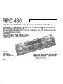
ATTACH SALES RECEIPT HERE
High-Power FM/AM/Cassette Receiver with Detachable Face
AutoradiolCassette AM/FM de Forte Puissance 2 Face Amovibie
Receptor FM/AM/Reproductor de Cassette de Alta Potencia y con
Cartitula Desmontable
‘,,
Rtidio FMIAM/Toca-Fitas de Alta
Potencia corn Face Removivel
Robert
Bosch Corporation
Sales GroupBlaupunkt Division
2800 South 25th Avenue
Broadview, Illinois 60153
288E7650
FCC WARNING
The equipment has been tested and found to comply with the limits for a Class B device, pursuant to Part 15 of the FCC Rules. These
limfts are designed to provide reasonable
protection against harmful interference in a residential installation. This equipment generates, uses, and can radiate radio frequency energy. and, if not installed and used in
accordance with instructions, may cause harmful interference with radio communications, However, there is no guarantee that radio interference will not occur in particular
installation. If this equipment does cause harmful interference to radio or television reception, which can be determined by turning the equipment off and on, the user is encouraged
to consult the dealer or an experienced radio/TV technician for help.
You are cautioned that any changes or modifications not expressly approved in this manual could void your authority to operate this equipment.
OWNER’S RECORD
The model and warranty numbers are located on the top of the unit. Record the serial number in the space provided below. Refer to these numbers whenever you Call upon your
Blaupunkt dealer regarding this product.
Warranty Number
FEATURES
Congratulations on your
purchase of this Blaupunkt FM/AM/Cassette Receiver. Its Optimum Reception Control (ORC IV) quartz FM and AM Tuner and high-quality, cassette tape
player provide the ultimate in sound reproduction.
l Audio
Features:
l General
Features:
. Cassette Features:
l Tuner Features:
- Detachable Faceplate for Securfty
- Autoreverse Cassette Mechanism
- 4 x 36 Watt Max. Integrated
- ORC IV Tuner
Amplifier
Switchable
Clock/Function LCD Display
- True Fast-Forward/Rewind
- 12 FM/6 AM Presets
- Volume/Balance/Fader Controls
- Quick-Connect Wire Harness
- Hard Pemtalloy Tape Head
Travelstore FM/AM
- Adjustable Turn-On Volume-Level
- 176 x 50 x 153.5 mm (7 x 2 x 6 in.)
- Automatic and Manual Tuning
- Separate Bass and Treble Controls
DIN Chassis
Your unit’s detachable front faceplate makes the unit useless to would-be thieves.
- Snap-In DIN Sleeve 8 Mounting Hardware
PRECAUTIONS
. If your vehicle was parked in direct sunlight resulting in a considerable rise in temperature inside the vehicle,
allOW the Unit t0 COOf
off before operating your unit.
. If no power connection is supplied to the unit, check the connections first, If everything is in order, check the fuse.
l If no sound comes from the speakers of a two-speaker system, set the fader control to the center position.
l You are cautioned that any changes or modifications not expressly approved in this manual could void your warranty.
. If you have any questions or problems concerning your unit that are not covered in this manual, please contact your Blaupunkt dealer.
DETACHABLE FACE
Detaching & Attaching the Face: The face of this unit can be detached and taken with you to prevent
It from betng stolen
Detaching the Face: Before detaching the face, be sure to press the PWR Button first. Then press the
REL (Release) Button and detach the face by gently pulling it off as Illustrated.
Note: Do not pull it straight out from the chassis. Be sure not to drop the face when detaching it from
the chassis.
I
Attaching the Face: Apply the right hand side of the face to the chassis by sliding (part B) of the face to (part A) at the front of the chassis. Gently push the left side of the face
against the front of the chassis until it snaps into place.
Note: Make sure that the face is inserted right side up. Do not press against the display window. Do not press hard against the face when attaching it to the chassis, it may be easily
attached with gentle pressure. Do not expose the face to direct sunlight, heat sources such as hot air ducts or leave it in a humid place. Never leave it on the dash board of a vehicle
parked in direct sunlight, where there may be a considerable rise in temperature inside the vehicle.
Afflxlng Faceplate For Retail Display: The faceplate can be affixed to the units chassis, which is desirable for a retail display, for example. This should only be done in situations
where the unit can be accessed from behind the mounting surface. Once the faceplate is affixed, the release keys cannot be used to remove the chassis. To affix faceplate, obtain
the small bolt (M2.6 x 10) from hardware pack and drive it into the upper hole at the front of the left side of the chassis using a Phillips screwdriver. The bolt will self-thread the hole.
(See above*)
ELECTRICAL CONNECTIONS AND INSTALLATION
@k?#&‘>@! To avoid the aggravation of costly mistakes and serious damage that could make you feel this way. please carefully read all of the instructions before you begin. You’ll
be glad you did!
GENERAL RECOMMENDATIONS
If you’re not confident that you can install the unit correctly, have it installed by a qualified Blaupunkt installation technician.
Use this unit only with negative ground 12 Volt (11-16 Volt) direct current (DC).
l Be sure to detach the faceplate before you start to connect or install the unit.
l If you use the unit’s connector with or without an adapter, make sure that function of the leads (wires) of the connector match the function of the leads in the mating connectors!
- If your vehicle’s radio wire harness is not compatible with this unit’s harness connector, you can either a. buy an adapter harness at a car audio store -or- b. cut off the units
connector and use a different type of connection.
l We recommend making and testing all electrical connections before installing the unit.
. Connect the leads (wires) according to instructions and diagram below unless the speaker’s or amplifier’s manual states that this is O.K.
l
l
ELECTRICAL CONNECTION INSTRUCTfONS
Disconnect the vehicle battery’s negative terminal before making connections.
: Before any other connections are made, you must first connect the antenna in order to avoid damage from mis,viring.
3 Connect speakers following the guidelines in the SPEAKER CONNECTION section below.
4. Connect the black (power ground) lead to a grounded metal part on the vehicle. We recommend grounding all audio system black ground leads (head unit, CD changer, etc.) to a common
grounding point, preferably a non-painted surface under the instrument panel.
Connect the yellow (constant power) input lead to a source of constant battery power, preferably a terminal to an appropriate slot in the fuse box.
Connect the red (turn-on power) input lead only after the other leads are connected. Be sure to connect the red lead to a positive (+) 12 Volt power terminal that is energized only when the
ignition key is set to the on position or accessory position.
7 Cover the ends of any unused leads with electrical tape. This will prevent them from touching the vehicle or each other and causing a short-circuit and damage to the radio or vehicle,
6 Reconnect the vehicle’s battery
9 Venfy that no fuses have blown
10 Plug the harness into the ““0
11 Attach the faceplate and test the “not
Once the connections have been successfully made, you can begin to install the unit
5.
6.
SPEAKER CONNECTfONS
You can connect a speaker (regular, co-axial or hi-axial speakers or component speaker system, all hereafter referred
to simply as “speaker’) to each of the units’ four pairs of speaker leads.
l
Connecting the Speaker Leads
To prevent short circuits or serious damage to the unit and/or speakers:
l Connect the speaker leads only as indicated in the wiring diagram.
l Only use speakers that have impedance ratings of 4 ohms or higher and have power-handling capabilities greater than
the head unit’s stated power level.
l The units internnl
amplifier is designed to handle a 4-ohm load on each pair of speaker leads.
l DON’T connect two speakers to a single pair of speaker leads (“in parallel”) unless both speakers each have at least 6
ohms impedance.
l DON’T connect the left and right speaker leads to each other or to the same speakers,
l DON’T connect the front and rear speaker leads to each other or to the same speakers.
l DON’T connect the negative speaker leads to each other.
l DON’T connect the positive speaker leads to each other.
l DON’T connect any active speakers (with built-in amplifiers) to the speaker leads.
Adding CD Changer: You can easily play compact discs through this unit by adding the Blaupunkt CDC-RF6 6-Disc
Compact Disc Changer. The space-saving CDC-RF6 easily plugs into the units antenna jack and comes complete with its
own commander control. See your Blaupunkt dealer for details!
INSTALLATION
Recommendations
* Carefully choose the mounting location so that the unit won’t interfere with normal driving.
* Avoid mounting locations where the unit would be subject to high temperatures, such as from direct sunlight or hot air from the heater, or where it would subject to dust, dirt or excessive
vibration
* The Illustration below shows a typuzal installation, however, you may need to adjust the s’tstaltatlon. depending on the unit. If you have questions or need additional installation
hardware, consult your Blaupunkt dealer.
l Make sure the uniiis firmly anchored (preferably at both front and back)
Mounting The Unit in Most Dashboards
and does not vibrate.
1 Install the Sleeve in the dashboard.
2 Select and bend the appropriate tabs to hold the sleeve firmly in place.
3 A. Attach the Mounting Strap to the underside of the dashboard, using screw.
B. Attach the back of the unit to the mounting strap using the support stem bolt and hardware.
Bend these tabs
Mounting the Unit in a Japanese Car
You may have difficulty mounting this unit in some Japanese cars.
In this case, consult your Blaupunkt dealer.
Removing the Unit
Use the Release Keys as shown below. Keep them in a safe place in case You need them
in the future.
1
f-gq
@,
MAINTENANCE
Fuse Replacement
When replaclng the fuse. be sure to use one with the correct amperage, whtch will be slated on the fuse case. Never use a fuse that has a stated amperage exceeding the one
supplied for this unit. as this could cause malfunction and serious damage to the unit.
SPECIFICATIONS
Audio Power Specifications
Power Output and Total Harmonic Distortion: 10 watts per channel minimum continuous average output into 4 ohms, 4 channels driven, from 30-15.000 Hz with no more than 1%
total harmonic dIstortIon
.
Other Specifications
Tuner
FM
Tuning Range:
87.5 - 107.9 mHz
Audio
10.7 mHz
IntermedIate Freouencv:
Speaker Impedance:
4-8 ohms
18
dBf
FM Mono Sensitiiity: ~’
Maximum imp Power:
30 Watts x 4 (at 4 ohms)
Selectivity:
75 dB at 400 kHz
iowansx4
RMS Power:
Signal-to-Noise Ratio:
85 dB (stereo), 70 dB (mono)
Bass Control:
+iO dB @ 100 Hz
Harmonic distortion at 1 kHz:
0.7% (stereo), 0.5% (mono)
*lOdB@ 10kHz
Treble Control:
Separation:
30 dB
. . Cassette
Frequency Response:
30-l 5,000 Hz f 3 dB
Signal-to-Noise Ratio:
53 dB
.bM
..
Tape Wow and Flutter:
0.10%
Tuning Range:
530 - 1,710 kHz
Tape Frequency Response:
50-l 5,000 Hz * 3 dB
Seek lo sensitivitv
55 dBpV
General
Seek sensitivity: ’
35 dBpV
Dimensions (w/o proiectinq parts/controls): 178 x 50 x 153 mm
45”
_ _kH,._
Intermediate Frequency:
7 x 2 x 6 in.
Signal-to-Noise Ratio:
45 dB
Mass:
Approx. 1.4 kg (3.0 lb.)
Design and specifications subject lo change withouf notice.
Power Requirement (neg. gmd.):
12 V DC car battery
Operating Temperature:
15°F to 12O’F. -10°C to 50°C
l Untt
l Faceolate
Supplied Accessories:
r
l Mounting
Hardware
* DIN Sleeve
l Owner’s Manual In English, French, Spanish and Portuguese
1
INSTRUCTIONS - GENERAL OPERATION
RADIO OPERATION
“Press” means momenlaly press of less than l/Z second
Band Selection
Press the BND Button as needed to access the desired band, FMI FMII or AM.
Turning Unit On
Vehicle lgnlbon must be on To turn unit on. press PWR Button.
Turning Unit Off
Press the PWR Button to turn the u”,t off
Volume
Press + or-to quickly increase or decrease the volume to the desired level. The volume
level is indicated in lhe Display Window. To make a fine adjustments to the volume level.
press the other part of the button before the volume level disappears from the display.
You can then gradually adjust the volume I” either direction, making precise adjustment
easy.
Adjustable Turn-O” Volume
First adfust the volume to the (maxtmum) volume level dewed when the unit IS turned on
Press and hold the PWR Button for more than two seconds The untt turns off and the
turn-on volume level IS memowed When the unit 8s turned cm. the volume wll be at the
mamonzed Iavel. avan II the unit was turned off while the volume was at a hlgher level
However, II the volume IS turned off when the volume level IS lower than the stored TumOn volume level. the volume wit be at the lower level when the untt IS turned back on
Setting the Clock
Turn tha unll on Press the AUD Button for four seconds until the ckxk starts bltnkmg
(The display wtll change after two seconds Ignore thls and c~nbnue to hold for two more
seconds ) Once the clock starts blmkmg. Press the A Button to set the hour, and press
the V Button to sat the mtnutes (To change the minute lndlcatot to the nearest hour ( 00),
you can press the BND Button Press the AUD Button agal” to acttvata tha clock
)
Changing the Information Displayed
* To change the display priority in the radio mode from clock lo function or funcbon to
clock. press the AU0 Button for hvo seconds The display prlonty changes
* To change the display temporarily in the radio mode from clock to funcbon or
funcbon to clock, press and release the AU0 Button After fwa seconds, the dtsplay
changes back to the pnonty tnformatlon.
’
Bass and Treble
Press and release as many times as needed AUD Button to select the Bass made. once
mare to reach the Treble mode. The level is indicated in the Display Window. Press the +
Button or - Button 10 increase or decrease the level:
BahCe
Press AU0 Button as needed to select the Balance made. The balance is indicated in the
Display Window. Press the + Button to increase the left speaker output or press the Button to increase the right speaker output to the desired level:
Fader
Press AU!3 Button as needed to select the Fader mode. The level of output for front and
back speakers is indicated in the Display Window. Press the + Button to decrease the
rear speaker output. Press the-Button to decrease the front speaker OUIDU~:
* five seconds after you complete your adfustments, the untt wll automabcally return lo
the volume mode and the display wit revert back to the pnonty dtsplay, clock or funcbon.
YOU can also press and release AUD as needed lo return to VOLUME, which appears
after FADER ,n the AUD Button cycle.
AUD Button Summary
* Pressing and ralaasmg the AUD Button accesses these modes I” this succass~on.
* Temporary Dtsplay Change(s), Bass, Treble. Balance, Fader. Volume.
* Prassmg the AUD Button for two seconds chanqas the dtsplav
.,.~nor,tv between clock
and function.
Pressing the AUD Button for four seconds accesses the time adjustment mode.
* Whtle in any AUD mode. if no button is pressed for
seconds, the unit returns to the
volume adjustment mode and priority display.
,
*
four
Automatic Stereo/Mono Reception Adjustment
When an FM stereo program with a signal strength of at least 60 dBf is tuned in, me
stereo indicator (a “) appears in the Display Window. If the FM stereo program is weak
and noisy, the unit automatically blends the signals, eliminating the noise and gradually
converts to the monaural or “mono” made. The sterao symbol will disappear from the
Display.
Automatic Seek Tuning
Select the desired band. Press and release the A or V button to seek the next receivable
station. To stop seeking and return to the previously tuned frequency, press the other of
the A or V buttons. If the frequency is already stored on a preset button on the active
band. the preset number will appear briefly.
Manual Tuning
Select the desired band. To begin manual tuning, press and hold the h or V button lor
0.5 seconds. Five seconds after you complete your adjustments. the Tuning Controls
(A V) Buttons revert to Seek Tuning. If the frequency is already stored on a preset button
on the active band, the preset number will appear briefly.
Travelstore
This feature allows you to automatically store 6 receivable FM and 6 receivable AM
stations, which is especially handy when you travel to a different reception area.
Select the desired band. The” press BND Button again for 2 seconds. The band
indkxtor begins to blink. Beginning with the last station received the unit automatically
scans the band for the six stations with strong signals. Once completed, the unit returns
to the previously-tuned frequency.
Selecting preset SIotlons
Choose the desired band using the BND Button. Press the preset button that has the
desired station.
Manually Storing Individual Presets
1. Tune in the desired station using seek or manual tuning.
2. Press the preset button on which you want to store the station for 2 seconds. To
confirm that the station is stored, the audio mutes temporarily, the frequency blinks in
the display, and the preset number appears briefly.
CASSElTE PLAYER OPERATION
Cassette Tape Play:
* lnselt cassette into Cassette Door. Note: Make sure that the side of the cassette with
the tape exposed is facing to the right side and that all slack has bee” removed lrom
the tape prior to insertion.
* The insertion of the cassette will automatically override the radio, and the cassene will
begin to play. When the cassette deck is being used, the display will indicate which
direction the tape is going.
* The tape will continue to play until ejected after which the radio will play.
Autoreverse Tape Function
* Automatic: When the end of the tape (side A or 8, program 1 or 2) is reached, the
tape will automatically reverse diraction and play the other side of the tape.
* Manual: To reverse tape direction during playback, press the PROG (Program)
Buttons. The change in direction and in tape program will be confirmed in the Display.
Fast Winding of Tape
No matter which side of the lapa that is playing:
. To fast-forward the tape. press the FF Button. The direction arrow will blink to confirm
the fast-fonvardmg.
* To fast-rewind the tape, press the FR Button. The direction arrow stays on and the
opposite arrow blinks to confirm the fast-rewinding.
Ejactlng The Tape
Press the Cassette Eject Button to eject the tape. The radio will play.
TROUBLESHOOTING GUIDE
The following check wll assist in the correction of most problems which you may ancountar with your unit. Before going lhrough the check list below, refer back to the connection and
operating procadures.
General
CauselSolutlo”
Trouble
No sound.
* Adfust the volume wth the + button.
. With a P-speaker system, set the fader control to the center postbon.
Indications do not appear on the
display window.
* Remove the front panel and clean the connectors wtth a cotton swab and isopropyl alcohol (90% or htgher) with a” in/out
mobon -- NOT a side-to-stde mobon
Radio reception - (Make sure Ihe antenna Is connected, extended. and dry Inside)
I
Trouble
Preset statlons are not receivable.
* The broadcast IS too weak.
Automatic tuning Is not possible
* The broadcast IS too weak --> Use manual tuning
Travelstore feature does not complete
storing of six stations.
. Not enough broadcast frequencies are recenable.
If the above mentioned solutions do not help to improve the situation, consult your nearest Blaupunkl dealer or in the USA call 1-600-266-2526
For dealer referral or product brochure call 1-600-950-2526.