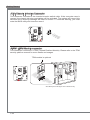
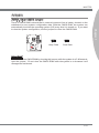
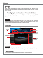
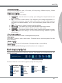
1
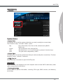
Getting Started
JFP1, JFP2: Front Panel Connectors
2
.+
8 .
6 .+
4 .
These connectors connect to the front panel switches and LEDs. The JFP1 connector is
compliant with the Intel® Front Panel I/O Connectivity Design Guide. When installing the
front panel connectors, please use the enclosed mConnectors to simplify installation.
Plug all the wires from the computer case into the mConnectors and then plug the
mConnectors into the mainboard.
r
ake
Spe
zer
Buz
D D
in E LE
P rL d
o e n
.N w e d
7 .Po sp n
5 .Su rou
3 .G
1
JFP2
P
o
w
e
r
0
in
P o 8. +
.
.N
6
.
4 +
.
2
e
ch
w
it
o
w
1
S
P
r
L
E
D
ch
it
w
d
S
e
t
rv se
D
E
se e
L
e
R
D
.R
D
9 .+
H
7 .
5 .3 .+
1
JFP1
Important
• On the connectors coming from the case, pins marked by small triangles are positive
wires. Please use the diagrams above and the writing on the mConnectors to
determine correct connector orientation and placement.
• The majority of the computer case’s front panel connectors will primarily be plugged
into JFP1.
JAUD1: Front Panel Audio Connector
This connector allows you to connect the front audio panel located on your computer
case. This connector is compliant with the Intel® Front Panel I/O Connectivity Design
Guide.
ct
te
e
D
e
n
o
n
h
io
P
ct
d
e
a
e in et
.H P D
0 o
1 .N IC
8 .M C nd
6 N ou
.
4 Gr
.
2
io
n
L
e D
n
o N
h E R
P _S ne
d
o
a E h
e NS P
.H E d
9 .S a R
7 .He IC L
5 M IC
.
3 .M
1
1-26
MS-7752
JUSB1~3: USB 2.0 Expansion Connectors
This connector is designed for connecting high-speed USB peripherals such as USB
HDDs, digital cameras, MP3 players, printers, modems, and many others.
115V
Chapter 1
d
C un +
.N o 1
0 r B 11 .G
8 US B
. S
6 .U C
4 VC
.
2
in
P nd
o u +
.N ro 0
9 .G SB 07 U B
.
S
5 .U CC
3 .V
1
* The MB layout in this figure is for reference only.
USB 2.0 Bracket (optional)
Important
Note that the VCC and GND pins must be connected correctly to avoid possible damage.
JUSB4: USB 3.0 Expansion Connector
The USB 3.0 port is backwards compatible with USB 2.0 devices. It supports data transfer rates up to 5Gbits/s (SuperSpeed).
115V
N
D
_ DP
in
N
P r X _
D
o e _R X
_ P
C D
.N w 3 R
_ _
0 o B _
2 .P S B3 nd X _C
T
9
1 8.U S ou _ X
1 7.U Gr B3 _T
1 6. S B3 nd 1 .U S u .0 +
o
5
1 .U r B2 .0
4
1 3.G S B2
1 2.U S
1 1.U
1
N
D
_ DP
N
r X _
D
e R X
_ P
w _
o B3 _R _C _D
.P S 3 d X C
1 U B n T _
.
2 .US rou 3_ TX
3 .G SB 3_ d 4 .U B n 0
5 US rou 2. 0 +
.
6 .G SB 2. nd
7 U B u
. S
8 .U ro
9 0.G
1
* The MB layout in this figure is for reference only.
USB 3.0 Bracket (optional)
Important
• Note that the VCC and GND pins must be connected correctly to avoid possible
damage.
• To use a USB 3.0 device, you must connect the device to a USB 3.0 port through an
optional USB 3.0 compliant cable.
1-27
Getting Started
JCI1: Chassis Intrusion Connector
This connector connects to the chassis intrusion switch cable. If the computer case is
opened, the chassis intrusion mechanism will be activated. The system will record this
intrusion and a warning message will flash on screen. To clear the warning, you must
enter the BIOS utility and clear the record.
d
n
u RU
ro T
.G IN
2 .C
1
JTPM1: TPM Module connector
This connector connects to a TPM (Trusted Platform Module). Please refer to the TPM
security platform manual for more details and usages.
TPM module is optional
115V
3
in
p 2
ta in
a p 1
d ta pin 0
n
e s & da ta pi
m s & da ta
a
ra re s
F d s & d
C ad dre ss &
P
re s
.L C d d s
3 P a d re
1 1.L C a dd et
1 .LP C a es k
9 .LP C R loc
7 .LP C C
5 .LP C
3 .LP
1
d
n
u d
r
ro un n r
e
.G ro Pi we Q r ow
4
1 2.G o Po IR we y p
l
1 .N
a o b
V
i
0
1 .5 er P nd
8 .S 3V ta
6 .3. S
4 .3V
2
* The MB layout in this figure is for reference only.
1-28
MS-7752
JDLED3: Voice Genie Connector (optional)
This connector is used to link to the voice control module (optional). Please refer to its
user guide for more details and usages.
in
p
d
n d
u rve
ro se d in
p
.G e n l in
u
p
3
1 .R ro tro l in
11 .G on tro l p
o
n
9
C
tr
.
7 .Co n B
o
5 C S
.
3 .5V
1
Chapter 1
in
p n
l i
o p
tr l
n o
in
o tr
p
n
n
.C o Pi ol
4
in
1 2.C o tr
p
1 .N n 3 l pin
o
0
1 .C C tro l
8 .VC n ro
t
6 Co n
.
4 .Co
2
JTURBO1: MultiConnect Panel Connector (optional)
This connector is used to connect an optional front panel for controling the OC Genie and
some additional functions. Please refer to its user guide for more details and usages.
in
lP
o
tr
n O
o RB
.C
2 .TU
1
in
P O
o RB
.N
4 .TU
3
JCOM1: Serial Port Connector
This connector is a 16550A high speed communication port that sends/receives 16
bytes FIFOs. You can attach a serial device.
in
P
o
.N S
0 T R
1 .C S
8 D R
.
6 T
.D N
4 SI
.
2
I S d
.R T n
9 . R r ou T
7 .G U
5 SO C D
.
3 .D
1
1-29
Getting Started
FV1: Voltage Checkpoints Connector (optional)
These voltage checkpoint are used to measure the current system voltages. A multimeter (not
included) will be required to check voltages. To check the voltage, please use the included
voltage checkpoint cables included in the mainboard package. Attach the positive lead of the
multimeter to the voltage checkpoint cable and the negative lead to the ground connector.
7
GND
GND
PCH_1P05
VCC_DDR
CPU_GFX
CPU_VTT
1
VCCP
Point
Description
GND (pin 6, pin 7)
Ground
PCH_1P05 (pin 5)
PCH 1.5 voltage. The PCH voltage is the voltage supplied to
the Platform Controller Hub.
VCC_DDR (pin 4)
Memory voltage. The DDR memory voltage is the voltage
supplied to the DDR memory modules on the mainboard.
Lower memory timings may require higher voltages to
maintain system stability.
CPU_GFX (pin 3)
The CPU_GFX voltage is the voltage supplied to the
integrated graphics processor located on the CPU.
CPU_VTT (pin 2)
CPU IO voltage (Uncore). The CPU IO voltage is the voltage
supplied to the Uncore on the CPU. Higher overclocks may
require a higher CPU IO voltage to maintain stability.
VCCP (pin 1)
CPU core voltage. The CPU voltage is the voltage suppoied
to the CPU core. Higher overclocks may require higher CPU
core voltages to maintain stability.
1-30
MS-7752
Jumpers
JBAT1: Clear CMOS Jumper
1
Keep Data
1
Clear Data
Important
You can clear the CMOS RAM by shorting this jumper while the system is off. Afterwards,
open the jumper . Do not clear the CMOS RAM while the system is on because it will
damage the mainboard.
1-31
Chapter 1
There is CMOS RAM onboard that is external powered from a battery located on the
mainboard to save system configuration data. With the CMOS RAM, the system can
automatically boot into the operating system (OS) every time it is turned on. If you want
to clear the system configuration, set the jumpers to clear the CMOS RAM.
Getting Started
LED Status Indicators
CPU_PHASE LEDs
CPU_PHASE LEDs
These LEDs will change according to CPU loading. The higher the power phase number, the more reliable the power flow to the processor.
1-32
Chapter 2
BIOS Setup
CLICK BIOS II is a revolutionary UEFI interface that
allows you to setup and configure your system for
optimum use. Using your mouse and keyboard, users can
change BIOS settings, monitor CPU temperature, select
the boot device priority and view system information
such as the CPU name, DRAM capacity, the OS version
and the BIOS version. Users can import and export
parameter data for backup or for sharing with friends. By
connecting to the Internet within CLICK BIOS II, users
can browse webpages, check mail and use Live Update
iyour system.
BIOS Setup
Entering
Power on the computer and the system will start the Power On Self Test (POST) process. When the message below appears on the screen, please <DEL> key to enter
CLICK BIOS II:
Press DEL key to enter Setup Menu, F11 to enter Boot Menu
If the message disappears before you respond and you still need to enter CLICK BIOS
II, restart the system by turning the computer OFF then back ON or pressing the RESET
button. You may also restart the system by simultaneously pressing <Ctrl>, <Alt>, and
<Delete> keys.
Important
The items under each BIOS category described in this chapter are under continuous
update for better system performance. Therefore, the description may be slightly different from the latest BIOS and should be held for reference only.
Overview
After entering Click BIOS II, the following screen is displayed.
Temperature
monitor
Mode
selection
System
information
Boot menu
Boot device
priority bar
BIOS menu
selection
BIOS menu
selection
Menu display
Important
The pictures in this guide are for reference only and may vary from the product you purchased. Please refer to the actual screens of your system for detailed information.
▶ Temperature monitor
This block shows the temperature of the processor and the mainboard.
2-2
MS-7752
Boot device priority bar
This bar shows the priority of the boot devices. The lighted icons indicate that the devices are available.
High priority
Low priority
Click and draw the icon to left or right to specify the boot priority.
■
Boot device icon list
USB Drive
Hard disk
drive
Optical
disk
LAN
USB hard
disk drive
USB
floppy
USB optical
drive
UEFI
BEV
Disable
2-3
Chapter 2
▶ System information
This block shows the time, date, CPU name, CPU frequency, DRAM frequency, DRAM
capacity and the BIOS version.
▶ BIOS menu selection
The following options are available:
■ SETTINGS - Use this menu to specify your settings for chipset features and
boot devices.
■ OC - This menu contains items of the frequency and voltage adjustments. Increasing the frequency can get better performance, however high frequency
and heat can cause instability, we do not recommend general users to overclock.
■ ECO - This menu is related to energy-saving settings.
■ BROWSER - This feature is used to enter the MSI Winki web browser.
■ UTILITIES - This menu contains utilities for backup and update.
■ SECURITY - The security menu is used to keep unauthorized people from making any changes to the settings. You can use these security features to protect
your system.
▶ Boot device priority bar
You can move the device icons to change the boot priority.
▶ Boot menu
This button is used to open a boot menu. Click the item to boot the system from the
device instantly.
▶ Mode selection
This feature allows you to load presets of energy saving or overclocking.
▶ Menu display
This area provides BIOS settings and information to be configured.
BIOS Setup
Operation
CLICK BIOS II allows you to control BIOS settings with the mouse and the keyboard.
The following table lists and describes the hot keys and the mouse operations.
Hot key
Mouse
<↑↓→← >
Description
Select Item
Move the cursor
Select Icon/ Field
<Enter>
Click/ Doubleclick the left
button
<Esc>
Jump to the Exit menu or return to the previous from
a submenu
Click the right
button
<+>
Increase the numeric value or make changes
<->
Decrease the numeric value or make changes
<F1>
General Help
<F4>
CPU Specifications
<F5>
Enter Memory-Z
<F6>
Load optimized defaults
<F10>
Save Change and Reset
<F12>
Save a screenshot to a FAT/FAT32 USB drive
Sub-Menu
If you find a point symbol to the left of certain fields,
that means a sub-menu can be launched for additional options. You can use the arrow keys or
mouse to highlight the field and press <Enter> or
double-click the left mouse button to enter the submenu. If you want to return to the previous menu, just press <Esc> or click the right
mouse button.
General Help
The General Help screen lists the appropriate keys to use for navigation. You can call
up this screen from any menu by simply pressing <F1>. Press <Esc> to exit the Help
screen.
2-4
MS-7752
SETTINGS
Chapter 2
System Status
▶ System Date
This allows you to set the system date that you want (usually the current date).
The format is <day> <month> <date> <year>.
day
Day of the week, from Sun to Sat, determined by BIOS. Read-only.
month
The month from Jan. through Dec.
date
The date from 1 to 31 can be keyed by numeric function keys.
year
The year can be adjusted by users.
▶ System Time
This allows you to set the system time that you want (usually the current time). The time
format is <hour> <minute> <second>.
▶ SATA Port1~6
Shows devices connected to specific SATA ports.
Important
If your device is not displayed, turn off computer and re-check SATA cable and power
cable connections to the device.
▶ System Information
Shows detailed system information, including CPU type, BIOS version, and Memory
(read only).
2-5
BIOS Setup
Advanced
▶ PCI Subsystem Settings
Press <Enter> to enter the sub-menu.
▶ PCIE GEN3
When set to [Enabled], the feature allows PCIe 3.0 slots support expansion cards
with PCIe generation 3.0 link speed. To avoid PCIe 1.0, 2.0 card compatibility
problems, you can set to [Disabled].
▶ PCI Latency Timer
Controls how long each PCI device can hold the bus before another takes over.
When set to higher values, every PCI device can conduct transactions for a longer
time and thus improve the effective PCI bandwidth.
▶ ACPI Settings
Press <Enter> to enter the sub-menu.
▶ ACPI Standby State
Specifies the power saving mode for ACPI function
[S1] Sleep Mode. Hardware remains on.
[S3] Suspend to RAM. Turns off hardware. (Recommended)
▶ Power LED
Configures how the system uses power LEDs on the case to indicate sleep/
suspend state.
[Blinking] The power LED blinks to indicate the sleep/suspend state.
[Dual Color] The power LED changes its color to indicate the sleep/suspend
state.
▶ Integrated Peripherals
Press <Enter> to enter the sub-menu.
▶ Onboard LAN Controller
This item allows you to enable/ disable the onboard LAN controller.
▶ LAN Option ROM
This item is used to decide whether to invoke the Boot ROM of the onboard LAN.
▶ SATA Mode
This item is used to specify RAID/ IDE/ AHCI mode for SATA port.
Important
You cannot switch between AHCI and IDE if you already have your operating system
installed. If you have installed your OS using AHCI and you clear your BIOS/reset to
default settings, you will need to change this function back to AHCI to ensure proper
functionality.
▶ Port 1~6 Hot Plug
These items are used to enable/ disable the SATA ports hot plug support.
2-6
MS-7752
▶ HD Audio Controller
This item allows you to enable/ disable the HD audio controller.
▶ HPET
The HPET (High Precision Event Timers) is a component that is part of the chipset.
You can enable it, and will provide you with the means to get to it via the various
ACPI methods.
▶ Integrated Graphics Configuration
Press <Enter> to enter the sub-menu.
▶ Integrated Graphics Share Memory
The system shares memory to the integrated graphics. This setting controls the
exact memory size shared to the integrated graphics.
▶ DVMT Memory
Specify the size of DVMT memory to allocate for video memory.
▶ IGD Multi-Monitor
Enables both integrated and discrete graphics at the same time. When disabled, it
will default to Initiated Graphics Adapter selection.
▶ Intel(R) Rapid Start Technology
Press <Enter> to enter the sub-menu.
▶ Intel(R) Rapid Start Technology
This feature can make your system fast start up from hibernation. This item allows
you to enable/ disable Intel Rapid Start Technology.
▶ USB Configuration
Press <Enter> to enter the sub-menu.
▶ USB Controller
This item allows you to enable/ disable the integrated USB 2.0 controller.
▶ Legacy USB Support
Enable or disable support for USB keyboards, mice and floppy drives. You will be
able to use these devices with operating systems that do not support USB.
▶ Hardware Monitor
Press <Enter> to enter the sub-menu.
▶ CPU Smart Fan Target
Controls CPU fan speed automatically depending on the current temperature and
to keep it with a specific range. If the current CPU temperature reaches the target
value, the smart fan function will be activated.
▶ SYS Fan1/ 2 Control
These items allow users to select how percentage of speed for the SYSFAN1/ 2.
2-7
Chapter 2
▶ Initiate Graphic Adapter
Choose which adapter you wish to make the primary option
[PEG] PCI-Express Graphics Device
[IGD] Integrated Graphics Display
BIOS Setup
▶ CPU/ System Temperature, CPU FAN/ SYS FAN 1/ 2 Speed
These items show the current status of all of the monitored hardware devices/ components such as CPU temperature/ system temperature and all fans’ speeds.
▶ Power Management Setup
Press <Enter> to enter the sub-menu.
▶ EuP 2013
Energy Using Products Lot 6 2013 (EUP) reduces power consumption when system
is off or in standby mode.
Note: When enabled, the system will not support RTC wake up event functions.
▶ Restore after AC Power Loss
This item specifies whether your system will reboot after a power failure or interrupt
occurs. Settings are:
[Power Off]Always leaves the computer in the power off state.
[Power On]Always leaves the computer in the power on state.
[Last State]
Restore the system to the status before power failure or interrupt
occurred.
▶ Wake Up Event Setup
Press <Enter> to enter the sub-menu.
▶ Wake Up Event By
Setting to [BIOS] activates the following fields, and use the following fields to set the
wake up events. Setting to [OS], the wake up events will be defined by OS.
▶ Resume By RTC Alarm
The field is used to enable or disable the feature of booting up the system on a
scheduled time/date.
▶ Date/ HH:MM:SS
If Resume By RTC Alarm is set to [Enabled], the system will automatically resume
(boot up) on a specific date/hour/minute/second specified in these fields (using the
<+> and <-> to select the date & time settings).
▶ Resume By PCI-E Device
When set to [Enabled], the feature allows your system to be awakened from the
power saving modes through any event on PCIe device.
▶ Resume From S3 by USB Device
The item allows the activity of the USB device to wake up the system from S3 (Suspend to RAM) sleep state.
▶ Resume From S3/S4/S5 by PS/2 Mouse/ Keyboard
These items determine whether the system will be awakened from what power saving modes when input signal of the PS/2 mouse/ keyboard is detected.
2-8
MS-7752
Boot
▶ Full Screen Logo Display
This item enables this system to show the company logo on the boot-up screen. [Enabled] Shows a still image (logo) on the full screen at boot.
[Disabled] Shows the POST messages at boot.
== Boot Option Priorities==
▶ 1st~9th Boot
These items are used to prioritize the installed boot devices.
▶ 1st~8th Boot
These items are used to prioritize the installed Hard Disk Drive/ CD/DVD ROM Drive/
USB HardDisk drives/ UEFI boot drives.
Save & Exit
▶ Discard Changes and Exit
Use this item to abandon all changes and exit setup.
▶ Save Changes and Reboot
Use this item to save changes and reset the system.
▶ Save Changes
Use this item to save changes.
▶ Discard Changes
Use this item to abandon all changes.
▶ Restore Defaults
Use this item to load the optimized default values set by the BIOS vendor.
== Boot Override ==
The installed storage devices will appear on this menu, you can select one of them be
a boot device.
▶ Built-in EFI Shell
Use this item to enter the EFI Shell.
2-9
Chapter 2
▶ Hard Disk Drive BBS Priorities/ CD/DVD ROM Drive BBS Priorities/ USB HardDisk
Drive BBS Priorities/ UEFI Boot Drive BBS Priorities
BIOS Setup
OC
Important
• Overclocking your PC manually is only recommended for advanced users.
• Overclocking is not guaranteed, and if done improperly, can void your warranty or
severely damage your hardware.
• If you are unfamiliar with overclocking, we advise you to use OC Genie for easy
overclocking.
▶ Current CPU / DRAM Frequency
These items show the current clocks of CPU and Memory speed. Read-only.
▶ CPU Base Frequency [10KHz]
Allows you to set the CPU Base clock (in 10KHz increments). You may overclock the
CPU by adjusting this value. Please note that overclocking behavior and stability is not
guaranteed.
▶ Adjust CPU Ratio
Controls the multiplier that is used to determine internal clock speed of the processor.
This feature can only be changed if the processor supports this function.
▶ Adjusted CPU Frequency
It shows the adjusted CPU frequency. Read-only.
▶ Adjust CPU Ratio in OS
Enable this item to allow CPU ratio changes in the OS by using MSI Control Center.
▶ Internal PLL Overvoltage
This item is used to adjust the PLL voltage.
2-10