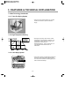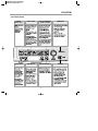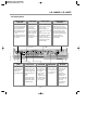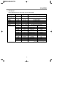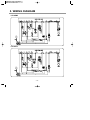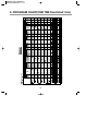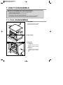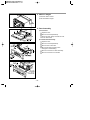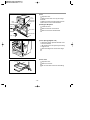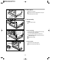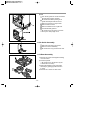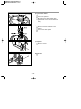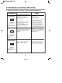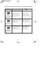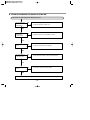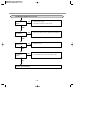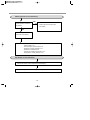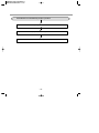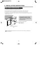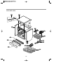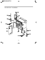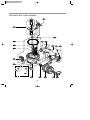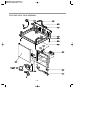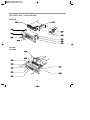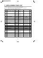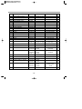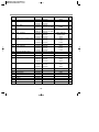
1
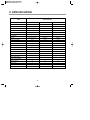
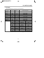
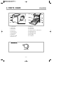
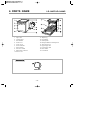
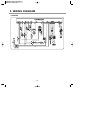
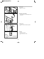
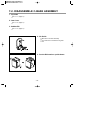
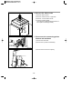
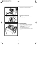
P/No. : 3828ED3001L
DISHWASHER
SERVICE MANUAL
NOTE
BEFORE SERVICING THE UNIT, PLEASE READ THIS MANUAL CAREFULLY
FOR SAFETY AND CORRECT SERVICES.
MODEL : LD-4050W
LD-14AW2, LD-14AT 2
CONTENTS
1. CAUTION .................................................................................................................................... 4
2. SPECIFICATIONS..................................................................................................................... 5
3. FEATURES & TECHNICAL EXPLANATION..................................................................... 6
4. PARTS NAME......................................................................................................................... 1 1
5.
WIRING
DIAGRAM ........................................................................................................... 1 3
6.
PROGRAM CHART (SCHEMATIC DIAGRAM) ............................................................ 1 5
7.
HOW TO DISASSEMBLE ................................................................................................... 1 7
8. TROUBLE SHOOTING METHODS ..................................................................................... 2 7
A. TROUBLE SHOOTING ACCORDING TO DISPLAYED ERROR MESSAGE ......... 2 7
B. TROUBLE DIAGNOSES AND REPAIR BY SYMPTOM .......................................... 2 9
9.
INSTALLATION INSTRUCTION ..................................................................................... 3 3
10. EXPLODED VIEW .............................................................................................................. 3 8
11. REPLACEMENT PART LIST............................................................................................ 4 4
-3-
CAUTION !
� DISCONNECT POWER CORD BEFORE SERVING
� RECONNECT ALL GROUNDING DEVICES
IMPORTANT SAFETY NOTICE !
This service information is intended for individuals
possessing adequate backgrounds of electrical,
electronic and mechanical experience.
Any attempt to repair this appliance may result in
personal injury and property damage.
The manufacturer or seller can not be responsible
for the interpretation of this information, nor can it
assume any liability in connection with its use.
-4-
2. SPECIFICATION
SPECIFICATION
ITEM
Model
Rated Voltage / Frequency
Installation
Place Settings
Product Dimension(mm)
Product Weight(Kg)
LD-4050W
LD-14AT2
LD-14AW2
AC 240V/50Hz
AC 240V/50Hz
AC 240V/50Hz
Free Standing / built-In
Free Standing / built-In
Free Standing / built-In
14
14
14
600(W)× 600(D)× 850(H) 600(W)× 600(D)× 850(H) 600(W)× 600(D)× 850(H)
52
52
52
Door Colour
White
Stainless Steel
White
Tub Material
Stainless Steel
Stainless Steel
Stainless Steel
Electronic(Fussy)
Electronic
Electronic
Rated Power(Watt)
2,210
2,210
2,210
Heater Power(Watt)
2,100
2,100
2,100
6
6
6
Upper Rack Position
Sliding Adjustable
Sliding Adjustable
Adjustable
Lower Rack
100% Fold down
100% Fold down
50% Fold down
Water Consumption(ℓ)
18 (Economy)
18 (Economy)
18 (Economy)
Power Consumption (kWh)
0.7 (Economy)
0.7 (Economy)
0.7 (Economy)
Operating Time (min)
84 (Economy)
84 (Economy)
84 (Economy)
Fan Dry System
Yes
Yes
Yes
Delay Start Function
Yes
Yes
Yes
Auto-Off Power Switch
Yes
Yes
Yes
Process Monitor
Yes
Yes
Yes
5
5
5
Nylon Coating
Nylon Coating
Nylon Coating
0.5 ~ 8
0.5 ~ 8
0.5 ~ 8
Control
Programs
Wash Level
Racks
Operating Water Pressure (Bar)
-5-
3. FEATURES & TECHNICAL EXPLANATION
3-1 New Technology Introduction
3-1-1. Turbo Fan Drying System
• Turbo fan drying system expels out hot and
humid air to enhance quick and effective
drying.
3-1-2. High Temperature Rinsing
• During the high temp. Rinse course, water
temperature in an dishwasher reaches 77°C,
considerably higher than the average rinse
temperature in conventional
dishwashers(65°C). This is how Rinse 77°C
can eliminate some bacteria such as
salmonella.
3-1-3. Turbo Spray System
• Turbo Spray System is elaborately designed to
achieve a more powerful and efficient wash.
You can see the excellent 3 rotating spray arm
with 5 directional waterjet.
-6-
LD-4050W
3-2. Display Panel
RINSE /
EXTRA HOT
HALF LOAD
DIAL (PROGRAM &
START / PAUSE)
TIME SAVE
CHILD LOCK
TIME DELAY
SPRAY INTENSITY
POWER
-7-
LD-14AW2 / LD-14AT2
3-2. Display Panel
DELAY START
BUTTON
TIME SAVE
HALF LOAD
• If you want to delay the
start of selected program,
press this button before
pressing start button.
• Pressing the delay time
will increase time by
1 hour.
• The delay start time can
be adjusted from 1 hour
to 19 hours.
• This function is
for saving time
and energy.
• With each press,
time save ON and
OFF is repeated.
• When select this
function, the
operating time will
be shorten.
• In case of small load, use
upper or lower rack only
to save energy.
• With each press, can
select upper or lower rack
only.
• In case you don’t select
this button, the machine
always works vario
washing, which operate
upper and lower spray
arm alternately.
REMAINING
TIME
• Indication of
remaining time
• Self diagnosis
and error
message display
POWER SWITCH
BUTTON
• For operating, press this
button first for power on.
• After operating, this button
automatically switches off for
safety and energy saving.
• If case of irregular surge
disturbances to the machine,
the power may be
automatically turned
off for safety.
CHILD LOCK
PROGRAM
RINSE/SANI
• Used to lock or
unlock the control
buttons to prevent
all the setting from
being changed by a
child.
• For
locking/unlocking,
press Delay Start
and T-Save button
simultaneously.
• When power is
on, program is
automatically set
to normal.
• If you want to
change the
program, press
the button and
set the program
you want to.
• With each press,
rinse+, rinse+ &
77。C sani rinse,
77。C sani rinse
is repeated.
-8-
START/PAUSE
BUTTON
• With each press,
Start and Pause
is repeated
during
operation.
• If the machine
remains in
Pause mode for
10 minutes, the
power is
automatically
turned off.
LD-4050W
3.3 TEST MODE
CHECK PROGRAM(START IN THE STATE OF THE CLOSED DOOR)
BUTTON
The number of
pushing button
DISPLAY
Load and Checking points
Half Load+Time
Delay+POWER S/W
1 TIME
n : 0H
All LEDs are lighting
Rinse
1 TIME
11 : 11
All LEDs are lighting
Half Load
1 TIME
12 : 22
All LEDs are lighting
Time Delay
1 TIME
13 : 33
All LEDs are lighting
Multi Spray
1 TIME
14 : 44
All LEDs are lighting
Time Save
1 TIME
15 : 55
All LEDs are lighting
Dial knob
1 Rotation
11 : 11 ~ 16 : 66
The LED of each course is lighting
1 TIME
n : 01
None
Intensive
2 TIME
Frequency
Water level sensor
Auto
3 TIME
n : 03
Washing motor
Economy
4 TIME
n : 04
Drain pump
Gentle
5 TIME
n : 05
Inlet valve
Quick
6 TIME
n : 06
Dispenser
Pre-wash
7 TIME
n : 07
Heater(for 10 sec.)
Time Save
8 TIME
n : 08
Fan motor
Wash
9 TIME
n : 09
None
Rinse
10 TIME
Temperature
Thermister
Dry
11 TIME
n : 11
Lower Nozzle
Lower
12 TIME
n : 12
Upper Nozzle
Upper
Start/Pause
AUTO OFF S/W
13 TIME
Micro S/W must be ON to operate HEATER
-9-
LD-14AT2/LD-14AW2
3.3 TEST MODE
CHECK PROGRAM(START IN THE STATE OF THE CLOSED DOOR)
The number of
pushing button
DISPLAY
Load and Checking points
Normal+Eco
+POWER S/W
1 TIME
n : 0H
All LEDs are lighting
Delay Start Key
1 TIME
11 : 11
All LEDs are lighting
T-Save Key
1 TIME
12 : 22
All LEDs are lighting
Intensive Key
1 TIME
13 : 33
All LEDs are lighting
Normal Key
1 TIME
14 : 44
All LEDs are lighting
Eco Key
1 TIME
15 : 55
All LEDs are lighting
Gentle Key
1 TIME
11 : 11 ~ 16 : 66
All LEDs are lighting
Quick Key
1 TIME
17 : 77
All LEDs are lighting
Pre-Wash Key
1 TIME
18 : 88
All LEDs are lighting
Half & Vario Key
1 TIME
19 : 99
All LEDs are lighting
Rinse Key
1 TIME
10 : 00
All LEDs are lighting
Start/Pause
1 TIME
n : 01
None
Time Save
2 TIME
Frequency
Water level sensor
Intensive
3 TIME
n : 03
Washing motor
Normal
4 TIME
n : 04
Drain pump
Eco
5 TIME
n : 05
Inlet valve
Quick
6 TIME
n : 06
Dispenser
Pre-wash
7 TIME
n : 07
Heater(for 10 sec.)
Wash 1
8 TIME
n : 08
Fan motor
Wash 2
9 TIME
n : 09
None
Rinse 1
10 TIME
Temperature
Thermister
Rinse 2
11 TIME
n : 11
Lower Nozzle
Dry
12 TIME
n : 12
Upper Nozzle
BUTTON
AUTO OFF S/W
13 TIME
Micro S/W must be ON to operate HEATER
- 10 -
LD-4050W
4. PARTS NAME
11. Adjust Leg
12. Upper Rack
13. Cutlery Rack
14. Detergent & Rinse Aid Dispenser
15. Vapor Vent Cover
16. Upper Spray Arm
17. Lower Spray Arm
18. Filter ASM
19. Lower Rack
1. Control Panel
2. Vapor vent
3. Door Handle
4. Front Cover
5. Lower Cover
6. Process Monitor
7. Power Switch
8. Drain hose
9. Inlet valve ASM
10. Power Cord
Inlet Hose
- 11 -
LD-14AT2/LD-14AW2
4. PARTS NAME
11. Adjust Leg
12. Upper Rack
13. Cutlery Rack
14. Detergent & Rinse Aid Dispenser
15. Vapor Vent Cover
16. Upper Spray Arm
17. Lower Spray Arm
18. Filter ASM
19. Lower Rack
1. Vapor vent
2. Control Panel
3. Door Handle
4. Front Cover
5. Lower Cover
6. Process Monitor
7. Power Switch
8. Inlet valve ASM
9. Drain Hose Connector
10. Power Cord
Inlet Hose
- 12 -
5. WIRING DIAGRAM
LD-4050W
- 13 -
5. WIRING DIAGRAM
LD-14AW2
LD-14AT2
- 14 -
6. PROGRAM CHART(SCHEMATIC DIAGRAM)
- 15 -
6. PROGRAM CHART(PGM TIME Flow-Default, Vario)
- 16 -
7. HOW TO DISASSEMBLE
BEFORE DISASSEMBLING THE DISHWASHER ;
1) Remove the plug from electric outlet to avoid electric shock.
2) Close the Water Tap(faucet).
3) Remove all dishes and items in the dishwasher.
4) Remove the Lower Rack and the Upper Rack.
5) If necessary, remove the inlet hose and drain hose to avoid the hose damages.
6) Prepare some towels to avoid floor wet by the water left in the dishwasher.
7-1. FULL DISASSEMBLE
1. Top Table
1) Remove the rear 2 screws.
2) Pull and lift the top table.
2. Low Cover
3. Cabinet-R/L
1) Cabinet-R
Remove front 4 screws.
Remove rear 3 screws.
2) Cabinet-L
Remove front 4 screws.
Remove rear 3 screws.
- 17 -
4. Balance weight
1) Remove side 4 screws.
2) Lift the balance weight.
5. Door Assembly
1) Front Cover
Open the door.
Remove 6 screws(stainless).
Close the door slowly and remove front
cover downwards.
2) Control Panel Assembly
Open the door.
LD-4050W
Remove 4 screws(stainless).
Remove wire connection.
Be sure the wiring should not be
changed in reassembling.
Remove 3 screws for Latch assembly
Remove 5 screws for Controller.
LD-14AW2
LD-14AT2
- 18 -
3) Fan
Open the door.
Out
Cover
Inner
Cover
Remove the outer cover by removing 1
screw.
Detergent
Dispenser
Remove 2 fixing screws inside and turn
the Inner Cover counterclockwise.
4) Detergent Dispenser
LD-4050W, LD-14AT2
Fan
Close the door.
Remove the wire connections.
Door Liner
Remove 6 screws with brackets.
LD-14AW2
Door Bracket
Fan
5) Door Spring (Right & Left)
Push the Spring upwards and take it off
from the Frame.
Be careful not to be injured by the sharp
edge of Tub.
Take the Hinge Link off from the Hinge.
6) Door Liner
Open the door.
Remove 4 screws.
Do not use other screws for assembling.
- 19 -
6. Base spacer
Remove 4 screws.
Lift the front side of dishwasher and pull
the base spacer forward.
7. Tub assembly
1) Nozzle
Pull up the nozzle.
2) Filter Assembly
Inner filter
Turn inner filter counterclockwise and lift
inner filter and middle filter.
Middle filter
You can disassemble inner filter and
middle filter by pulling opposite direction.
Micro filter
Lift up main filter.
Lift up micro filter.
Main filter
3) Nozzle Holder
Disconnect the water guide
Remove 4screws and lift it up
- 20 -
4) Tub
Turn the air guide nut counter-clockwise.
(Special tool might be needed.)
Be careful the rubber packing of air
guide assembly should not be lost.
Remove 4 screws for sump holder .
Remove side 8 screws.
Remove 2 Earth screw of right side.
Lift tub assembly upward.
Be careful not to be injured or scratch
floor by the sharp edge of tub.
8. Air Guide Assembly
Disconnect the wiring connection.
Remove 3 hoses assembly.
Be careful the o-ring should not be lost.
9. C-Base Assembly
1) Remove the screw which tighten washing
motor and base.
2) Lift them upward.
Be careful not to wet the floor by the
water left in the sump.
3) Detach the washing motor and heater
assembly by pulling opposite direction
to sump.
4) Remove the 3 screw for drain motor.
- 21 -
5) synchronous motor
Remove the 2 screws.
Lift the cam upward.
Be careful not to install upside down.
(part number on the cam should face the
motor.)
6) Vario valve
Remove 4 screws and lift the cover
upward.
Lift the vario valve upward.
7) Capacitor
Remove 1 screw.
8) Inlet valve
Remove 2 screws.
- 22 -
9) Noise filter
Remove 1 screw.
10) Power cord assembly
Turn the power cord assembly 90º and
take it off.
11) Drain Hose
Pull the holder forward and upward.
12) Relay
Remove 2 screws.
LD-4050W has no relay.
- 23 -
7-2. DISASSEMBLE C-BASE ASSEMBLY
1. Top Plate
See 7-1. 1. (Page 17)
2. Low Cover
See 7-1. 2. (Page 17)
3. Cabinet-R/L
See 7-1. 3. (Page 17)
4. Air Guide
Disconnect 3 hoses assembly.
You need not to unscrew the air guide
nut.
5. Put the Dishwasher upside down.
- 24 -
6. Remove the side screws
1) Remove side 8 screws.
2) Remove 2 Earth screws of right side.
3) Remove 1 motor bracket screw.
4) Lift base upward slightly.
(You can’t lift up base perfectly because of
some parts connecting to base.)
7. Disconnect the connecting points
between tub and base
1) Disconnect noise filter.
2) Disconnect of powercord assembly.
3) Disconnect wire from the capacity.
- 25 -
4) Disconnect wire from the inlet valve.
5) Disconnect wire from the relay.
Now, you can remove the base from the
tub perfectly.
8. C-Base Assembly
You can repair the parts in the C-Base like
heater case, washing pump, drain motor
etc. you may refer to 7-1. 9. 2)~11)
(Page 21~23)
Don’t disassemble sump by 7-2.
If you want to disassemble the sump, follow
7-1.
- 26 -
8.TROUBLE SHOOTING METHODS
A. TROUBLE SHOOTING ACCORDING TO DISPLAYED ERROR MESSAGE
ERROR MESSAGE
INLET ERROR
displayed
Condition
Not reached to the normal water level in spite
of 10 min. water supply
DRAIN ERROR
POSSIBLE CAUSE
FOR ERROR OCCURRENCE
REMEDY
The Water Tap is not opened.
Open the Water Tap.
The Inlet Hose is kinked.
Repair the Inlet Hose.
The Filter of inlet valve clogged
a) Close the Water Tap.
by impure water.
The Inlet Water Valve is normal ?
b) Unscrew the Inlet Hose (Inlet Valve side)
c) Clean the Filter of Inlet Valve.
Replace or repair the Inlet Valve.
The water pressure is very low.
Check the water remain on the base.
( below 0.5 kgf/
1) Check the point of damages and
repair or replace the related parts.
2) Disconnect the inlet hose to
dishwasher to unlock the safety valve.
)
Inlet valve is blocked by safety
device for leakage sensing.
The Filter clogged.
Clean the Filter.
The Drain Hose kinked or blocked.
Remove the cause of kink or block.
The Drain Pump/Motor or circuit is
Replace the Drain Pump/Motor or
troubled.
repair the Circuit.
Water leakage in Hose connections.
Replace the connections of Hose.
Water is leaked by damages.
Check the point of damages and
displayed
Condition
Not fully drained out in
spite of 5 min. drain
operation
LEAKAGE ERROR
repair or replace the related parts.
displayed
Condition
The water level in Tub
goes down during
operation
- 27 -
ERROR MESSAGE
POSSIBLE CAUSE
FOR ERROR OCCURRENCE
REMEDY
EXCESS ERROR
The Inlet Valve is troubled.
Replace the Inlet Valve.
displayed
The Air Break is troubled.
Replace the air breaker.
Condition
The Sensor Assembly is troubled.
Replace the sensor assembly.
The Controller is troubled.
Repair or replace the Controller.
The Circuit of thermistor is troubled.
Repair the Circuit of thermistor.
Thermistor is troubled.
Replace the Thermistor.
The Controller is troubled.
Repair or replace the Controller.
The Circuit of Heater is troubled.
Repair the Circuit of Heater.
The Thermistor is troubled.
Replace the Thermistor.
The Heater is shorted.
Replace the Heater.
The Relay Circuit is troubled.
Repair the Relay Circuit..
Excessive water is supplied than normal water
level.(Automatically drain
Pump operated.)
THERMAL ERROR
displayed
Condition
The resistance of thermistor not normally out
put.
HEATER ERROR
displayed
Condition
The water is not heated
or the temperature in
the Tub is overheated
to over 95¡
- 28 -
B. TROUBLE DIAGNOSES AND REPAIR BY SYMPTOM
No Power on when the power button pressed.
The plug is correctly
inserted in the
Socket-Outlet?
NO
• Insert the Plug Correctly.
• Check the electricity is failed or not.
YES
The Fuse or
Circuit Breaker
of house is O.K?
NO
• Replace the Fuse or Circuit Breaker of house.
YES
The Thermal Fuse
is O.K?
NO
• Check the Thermal Fuse and replace it.
YES
The Power Switch or
the Circuit is O.K?
NO
• Check the Power Switch or the circuit and repair it.
YES
The C-Trans Circuit
is O.K?
NO
• Check the C-Trans Circuit. and repair it.
YES
C h e c k t h e C o n t r o l l e r. ( P o w e r C i r c u i t )
- 29 -
The Wash Pump/Motor does not run.
The Door is tightly
closed?
NO
• Close the Door Tightly.
• Check the Door Switch in Latch Handle.
YES
The Pump/Motor is
not blocked?
NO
• Remove the cause of block or replace the Pump/Motor.
NO
• Repair the circuit.
YES
The circuit of Pump/
Motor is O.K?
YES
The Thermal Protector of Motor is
tripped?
YES
• Cool the Motor Until the Thermal Protector reset.
NO
Replace the Pump/Motor
- 30 -
Washing Results are not Satisfactory
After washing, are there still
White deposits or streaks on
the dishes?
YES
ㆍ Reduce the amount of Rinse-Aid
(for Streak)
NO
After washing, are there still
food soils on the dishes?
YES
Check that : - the amount of detergent Correctly used or not
- Filters clogged or not.
- the holes of spray arms blocked or not.
- Utensils are correctly arranged or not.
- Utensils are overloaded or not.
- the spray arm rotating is obstructed or not.
- the program is correctly selected or not.
Dry Results are not satisfactory
Increase the amount of Rinse-Aid.(Set the number higher)
Select the Program that the Rinse temperature is higher.
- 31 -
Power Button not automatically off after operation.
Check the button is blocked by foreign materials.
Check the Power Switch.(Replace it, if necessary.)
Check the Controller.(Replace it, if necessary.)
- 32 -
9. INSTALLATION INSTRUCTION
Step1: Prepare Cupboard opening
1. This dishwasher is designed to fit to the size shown as below.
2. Select a location as close to sink as possible for easy connections to water and drain lines.
3. The dishwasher should not be installed more than 3 meters from sink for proper drainage.
4. If dishwasher is to be installed in corner, minimum 5 cm of space is required between the washer and an
adjacent cabinet or a wall.
If bare chipboard is adjacent to or above
the dishwasher, it should be sealed with
a waterproofing paint or sealant to prevent
swelling due to steam.
Cut out for hoses and electrical
cables on either side.
( approx.. 100 X 75 )
Cupboard Opening Dimension
( mm )
Ensure the floor under the dishwasher is at the same level as the rest of the room to allow for any
service requirements.
- 33 -
Step 2 : PREPARE ELECTRICAL WIRING
CAUTION
For personal safety, remove house fuse or open circuit breaker before installation.
Do not use an extension cord or adapter plug with this appliance.
Electrical and grounding connections must comply with the national electrical code/provincial and
municipal code and/or other local codes.
1. This appliance must be supplied with correct rating voltage and hertz as shown on instruction manual,
and connected to an individual, properly grounded branch circuit, protected by minimum 15 amp circuit
breaker or time delay fuse.
Wiring must be 2 wires with ground.
2. The power point must be in a accessible location adjacent to and not behind the dishwasher and within
1.2 meters of the dishwasher side. A correctly rated, wired and earthed extension cord may be used if
necessary.
(See Fig. A)
3. The power point must be correctly earthed, if in doubt, have it checked by a qualified Electrician. No
other appliance shall be connected to the same plug outlet by a double adapter or similar plug.
Step 3 : PREPARE DISHWASHER FOR INSTALLATION
1. Lay the dishwasher on its back.
2. Adjust the legs to the needed height of cabinet as shown at below.
- 34 -
Step 4 : INSTALL THE DISHWASHER IN CUPBOARD
1. Before sliding the dishwasher into the cupboard opening, all necessary final height adjustment and
balancing adjustment should be done using the spanner.
2. Slide the dishwasher into the cabinet opening carefully. Make sure that the drain hose inside the cabinet
should not be kinked or exceeded.
CAUTION
If the height of cupboard is below 850mm,
you should remove the top table by
unscrewing the 2 screws. (Two of rear)
- 35 -
Step 5 : DRAIN LINE CONNECTION
1. If the end drain hose does not fit to the drain line, use a piece of rubber connector (not supplied)
that must be resistant to heat and detergent and may be obtained from a plumbing shop.
2. There are 2 typical connections as shown in Figure A, B
¥ The recommended methods of drain hose connection must be adhered to within the areas of Water Board
Authority. Several other options are commonly used outside this area and local council or plumbers should
be able to advise of these.
¥ The S trap spigot must be drilled out cleanly and free of obstruction to its maximum internal diameter, if
used for drainage.
¥ To prevent syphoning, one of the following instruction methods must be followed :
■ When the drainage hose is connected to a sink S trap or waste disposal unit, the hose must be looped up
to the under side of the bench top and secured.
Fig. A
■ When the drain hose is connected to a separate stand pipe, it is essential that an air tight connection is
made. Refer to Fig. B
Fig. B . Drainage connection-stand pipe
- 36 -
Drain Hose Extension
■ Drain Hose extension kits are available from through your local service centre.
Extend drain Hose as shown below.
Step 6 : WATER SUPPLY CONNECTION
1. Connect the water supply hose to the valve behind dishwasher
and the water tap as shown in figure.
This dishwasher may be fed with either hot or cold water. If the
water can not be maintained below 65°C, the dishwasher must
be connected to cold water.
2. When connecting, the sealing tape or sealing compound should
be used to avoid water leaks.
Make sure that the line is not kinked or sharply bent.
Step 7 : FINAL CHECK AND ASSEMBLING
1. Securely hand tighten supply hose to water supply.
Plug power cord into an earthed power point and switch on.
2. Operate the dishwasher through one cycle (Quick cycle is recommended) to check for water leak
and operating conditions.
- 37 -
10. EXPLODED VIEW
LD-4050W
LD-14AT2
LD-14AW2
- 38 -
EXPLODED VIEW
- 39 -
EXPLODED VIEW - TUB ASSEMBLY
- 40 -
EXPLODED VIEW - SUMP ASSEMBLY
- 41 -
EXPLODED VIEW - BASE ASSEMBLY
- 42 -
EXPLODED VIEW - DOOR ASSEMBLY
LD-4050W
LD-14AT2
LD-14AW2
- 43 -
11. REPLACEMENT PART LIST
CAUTION : BEFORE REPLACING ANY OFTHESE COMPONENTS.
READ CAREFULLY THE SAFETY PRECAUTIONS IN THIS MANUAL
�NOTE : S(SAFETY PARTS), AL(ALTERNATIVE PARTS)
No.
*001
PART NAME
MANUAL ASSEMBLY, OWNERS
PART No.
APPLIED MODEL
SPEC&COLOR
Q'ty
3829ED3001Z LD-4050W
3829ED3003H LD-14AT2
3929ED3003A LD-14AW2
*002
BOX, CARTON
3890EZ3314A LD-4050W
3890EZ3314A LD-14AT2
3890EZ3314A LD-14AW2
*003
MANUAL, SERVICE
A001 TOP PLATE ASSEMBLY
3828ED3001L
English
3301ER1001F LD-4050W, LD-14AW2
WHITE
3301ER1001C LD-14AT2
A002 BLANCE WEIGHT
4866ED2003A
A010 CABINET
3112FD1079R LD-4050W, LD-14AW2
3112FD1079U LD-14AT2
A020 CABINET
3112FD1025R LD-4050W, LD-14AW2
3112FD1025U LD-14AT2
A030 BASE, CABINET
3040ED1001A
A040 COVER, LOWER
3550ED1001A LD-4050W, LD-14AW2
3550ED1001C LD-14AT2
1
WARM SILVER
1
WHITE
1
PURPLE GRAY
WHITE
1
PURPLE GRAY
1
WHITE
1
PURPLE SILVER
A050 NOZZLE ASSEMBLY(LOWER)
5249FD1168C
STAINLESS
1
A060 NOZZLE ASSEMBLY(UPPER)
5249ED1003A
DARK GRAY
1
A070 GUIDE ASSEMBLY(UPPER)
4975ED2003A
DARK GRAY
1
A080 RACK(CUP RACK)
3750FD2036C
DARK GRAY
2
A090 RACK(KNIFE RACK)
3750ED2002C
DARK GRAY
1
A110 BASKET ASSEMBLY, SPOON
5005ED2003B
DARK GRAY
1
A120 HARNESS, PWB
6877ED1011B LD-4050W
1
6877ED1011D LD-14AT2
6877ED1011C LD-14AW2
1
A130 HOSE ASSEMBLY, DRAIN
5215ED3001B
A140 RACK ASSEMBLY(LOWER)
3751ED1001J LD-4050W, LD-14AT2
DARK GRAY
3751ED1001H LD-14AW2
DARK GRAY
3751ED1002D LD-4050W, LD-14AT2
DARK GRAY
3751ED1002E LD-14AW2
DARK GRAY
A150 RACK ASSEMBLY(UPPER)
- 44 -
1
1
No.
PART NAME
PART No.
APPLIED MODEL
SPEC&COLOR
Q'ty
A155 GUIDE ASSEMBLY(RIGHT)
4975ED2002C LD-4050W, LD-14AT2
1
A156 GUIDE ASSEMBLY(LEFT)
4975ED2002D LD-4050W, LD-14AT2
1
A160 FILTER ASSEMBLY(CIRC)
6201EC1004F
A276 HOSE ASSEMBLY, INLET
3W40102H
1
F011 SPRING, HINGE
4970ED4004C
2
F013 CONNECTOR ASSEMBLY(MECH) 4933ED3002A
NOISE FILTER
HINGE ROPE
1
2
1
F021 RELAY
6921ED3001A LD-14AT2, LD-14AW2
F022 SENSOR ASSEMBLY
6501ED4001B
F040 GUIDE ASSEMBLY
4975ED1003C
AIR GUIDE
1
F050 NUT, DRAWING
4020ED3641C
AIR GUIDE NUT
1
F060 GASKET
4986FD3643A
AIR GUIDE GASKET
1
F113 ROLLER
4580FD3087C
8
F132 TUB GASKET
3920FD3079C
1
F174 BRACKET ASSEMBLY
4811FD3667A
1
F181 ROLLER
4580ED3001A
HINGE ROLLER
2
F191 GUIDE ASSEMBLY
4975ED1002A
WATER GUIDE
1
K001 DISPENSER
4924FD2123D LD-4050W
DARK GRAY
1
4924FD2123C LD-14AT2, LD-14AW2
DARK GRAY
K002 BRACKET ASSEMBLY
4810FD3805A
2
K003 PACKING
3940FD4149A
2
K010 COVER, FRONT
3122FD1049K LD-4050W, LD-14AW2
K110 BLOWER ASSEMBLY
WHITE
3122FD1049N LD-14AT2
STAINLESS
5835ED2001B LD-4050W
AIR MIXING
5835ED2001A LD-14AT2
AIR MIXING
1
1
5835FD2111C LD-14AW2
K121 BLOWER, IMPELLER(GASKET)
5834FD3095A
RUBBER, BLACK
1
K122 BLOWER, IMPELLER(PLASTIC)
5834FD3101A
INNER COVER
1
OUT COVER
1
K123 BLOWER, IMPELLER(STAINLESS) 5834FD3100A
K124 CONNECTOR(MECH), BLOWER
1
4932ED3002B LD-4050W
4932ED3001B LD-14AT2
K201 BUTTON, CONTROL
K202 DECO, PANEL
5020ED3002A LD-4050W
WHITE
5020ED1001B LD-14AT2
WARM SILVER
5020ED1001A LD-14AW2
WHITE
3806ED1001D LD-14AT2
WARM SILVER
- 45 -
1
1
No.
PART NAME
PART No.
APPLIED MODEL
3806ED1001C LD-14AW2
K203 WINDOW
SPEC&COLOR
Q'ty
WHITE
1
3790ED1001B LD-14AT2
3790ED1001A LD-14AW2
K204 DECO, KNOB
3806ED2001B LD-14AT2, LD-14AW2
K205 SPONGE
1
3806ED3002A LD-4050W
SILVER
1
3940FD4174D LD-4050W
3940FD4174C LD-14AT2, LD-14AW2
1
3720ED1002L LD-4050W
WHITE, ENGLISH
3720ED1001F LD-14AT2
WARM SILVER
3720ED1001B LD-14AW2
WHITE
K209 POWER SWITCH KNOB(BUTTON) 5020ED3003A LD-4050W
WHITE
4940ED2002B LD-14AT2
SILVER
4940ED2002B LD-14AW2
SILVER
K211 KNOB ASSEMBLY
4941ED3001A LD-4050W
ROTARY KNOB
1
K230 PLATE, CONTROL
3300ED3004N LD-4050W
WHITE
1
3300ED3001V LD-14AT2
BLACK
3300ED3001U LD-14AW2
SILVER
K208 PANEL, CONTROL
1
K250 PEB(PCB) ASSEMBLY, MAIN
6871EC1095A LD-14AT2, LD-14AW2
1
K251 PEB(PCB) ASSEMBLY, MAIN
6871EC1100B LD-4050W
1
K252 PEB(PCB) ASSEMBLY, DISPLAY
6871EC2031A LD-4050W
1
K260 LATCH ASSEMBLY
4027FD3621K LD-4050W
WHITE
4027FD3621H LD-14AT2
GRAY
4027FD3621F LD-14AW2
WHITE
4026ED3002A LD-4050W
WHITE
4026ED3001B LD-14AT2
GRAY
4026ED3001A LD-14AW2
WHITE
K262 LATCH, HANDLE
DARK GRAY
1
1
1
M001 HOLDER(NOZZLE HOLDER)
4930ED2003A
M002 DAMPER(W, PUMP)
4900ED4003A
M005 SUMP GASKET
4986ED3005A
M006 SUMP ASSEMBLY
3485ED1001E
1
M008 DAMPER
4900ED3001A
1
M018 GASKET
4986ED3001A
1
M023 DAMPER
4900ED4002A
1
M024 COVER, GUIDE
3550ED3009A
1
- 46 -
1
SUMP
1
No.
PART NAME
PART No.
APPLIED MODEL
SPEC&COLOR
Q'ty
1
M025 VALVE, CHECK
5220ED3001A
M026 MOTOR ASSEMBLY, WM
4681ED3001A
M027 SWITCH, MICRO
3W40025C
1
M028 CAM, SWITCH
4430ED4001A
1
M029 SUMP HOLDER
4930ED3011A
4
M051 MOTOR ASSEMBLY, PUMP
4681EA2001A
1
M060 PUMP ASSEMBLY, WASHING
5859ED1001A
1
M062 BRACKET, MOTOR
4810ED3003A
1
M070 FILTER ASSEMBLY, STAINLESS
5231ED2001A
1
M080 CASE ASSEMBLY
3111ED2002C LD-4050W
1
SYNCHRONOUS MOTOR
1
3111ED2002F LD-14AT2, LD-14AW2
M083 THERMISTOR ASSEMBLY
6322FD3671A
1
M086 SWITCH, MICRO
3W40025B
1
M087 SENSOR ASSEMBLY
6501ED2002A LD-4050W
1
M210 VALVE ASSEMBLY, INLET
5221ED1002A
1
M230 POWER CORD
6410FA3406X
1
M260 BASE, CABINET
3040ED1002A
1
M270 LEG
4778ED3001A
4
- 47 -