1
Micro-Portable Projector
LT150Z
English
User’s Manual
Deutsch
Français
Italiano
Español
Svenska
LIMITED WARRANTY
GARANZIA LIMITATA
Except as specified below, the warranty that may be provided by the
dealer covers all defects in material or workmanship in this product.
The following are not covered by the warranty:
A parte la specificazione seguente, la graanzia che potrebbe essere
fornita dal rivenditore copre tutti i difetti di materiali o nella lavorazione
in questo prodotto. I seguenti non sono coperti dalla garanzia :
1. Any product on which the serial number has been defaced, modified or removed.
2. Damage, deterioration or malfunction resulting from;
a. Accident, misuse, abuse, neglect, fire, water, dust, smoke, lightning or
other acts of nature, unauthorized product modification, or failure to
follow instructions supplied with the product.
b. Repair or attempted repair by non-authorized persons.
c. Any shipment of product (claim must be presented to the carrier).
d. Removal or installation of the product.
e. Any other causes which do not relate to a product defect.
3. Cartons, carrying cases, batteries, external cabinets, CDROM, or
any accessories used in connection with the product.
4. Removal or installation charges.
5. Cost of initial technical adjustments (set-up), including adjustment
of user controls. These costs are the responsibility of the dealer
from whom the product was purchased.
6. Payment of shipping charges.
1. Ogni prodotto che ha il numero seriale difettoso, modificato o
rimosso.
2. Danni, deterioramento o malfunzionamento risultanti da;
a. Incidenti, abuso, cattivo uso, negligenza, fuoco,
acqua,polvere,fumo,fulmini o altri atti naturali di tipo naturale, modifiche
inautorizzate del prodotto, o errori nel seguire le istruzioni fornite con
il prodotto.
b. Riparazioni o tentativi di riparazioni effettuati da persono non autorizzate.
c. Qualsiasi trasporto del prodotto (i reclami devono essere presentati
dal corriere).
d. Rimozione o installazione del prodotto.
e. ogni altra causa non relativa ad un deficit del prodotto.
3. Cartoni, scatole di trasporto, batterie, armadietti esterni, CDROM,
o qualsiasi altro accessorio annesso al prodotto.
4. Carichi di rimozione o installazione.
5. Costi di aggiustamenti tecnici iniziali (set-up), includendo i comandi
di regolazione. Il rivenditore dal quale avete acquistato il prodotto
è responsabile di ciò.
6. Pagamento delle spese di consegna.
GARANTIE LIMITEE
Mis à part les point indiqués ci-dessous, la garantie pouvant être
couverte par le revendeur comporte l'ensemble des défauts se
rapportant au matériel ou aux travaux d'assemblage sur ce produit.
Les points suivants ne sont pas couverts par la garantie:
1. Les produits dont les numéro de série a été effacé, modifié ou
retiré.
2. Dommages, dégâts ou dysfonctionnement suite à;
a. Un accident, mauvaise utilisation, abus, négligences, incendies, dégats
dûs aux eaux, à la poussière, à la fumée, aux éclairs ou autres
phénomènes naturels, à une modification non autorisée du produit, ou
à la non-conformité aux instructions fournies avec le produit.
b. Réparation ou tentative de réparation par des personnes non autorisées.
c. Toute expédition du produit (les plaintes doivent être adressées à la
société de frêt).
d. Démontage ou installation du produit.
e. Toute autre cause ne se rapportant pas à un défaut du produit.
3. Les cartons, boîtes, piles, caissons externes, CDROM, ou tout
autre accessoire utilisé avec ce poduit.
4. Prix de démontage ou d'installation.
5. Coût des réglages techniques de base (mise au point), incluant
les réglages des commandes utilisateurs. Ces coûts sont placés
sous la responsabilité du revendeur auprès duquel le produit a
été acheté.
6. Paiement des frais de transport.
BESCHRÄNKTE GARANTIE
Außer in den unten beschriebenen Fällen deckt die vom Händler
unter Umständen gewährte Garantie alle Material- oder
Herstellungsfehler dieses Produktes ab. In den folgenden Fällen wird
keine Garantie gewährt:
1. Wenn die Seriennummer des Produktes unleserlich gemacht,
geändert oder entfernt worden ist.
2. Bei einer Beschädigung, Beeinträchtigung oder Funktionsstörung,
die aus folgenden Fällen resultiert:
a. Unfall, falscher Gebrauch, Missbrauch, Fahrlässigkeit, Feuer, Wasser,
Staub, Rauch, Blitzeinschlag oder andere Naturereignisse, nicht
autorisierte Veränderungen des Produktes oder die Missachtung der
dem Produkt beigefügten Anleitung.
b. Reparatur oder der Versuch einer Reparatur durch nicht autorisierte
Personen.
c. Jeglicher Transport des Produktes (die Haftung liegt in diesem Fall bei
der den Transport durchführenden Person).
d. Entfernung oder Installation des Produktes.
e. Jegliche andere Ursachen, die nicht mit einem Defekt dieses Produktes
zusammenhängen.
3. Verwendung von Kar tons, Transpor tkisten, Batterien,
Außengehäusen, CD-ROMs oder anderem Zubehör zusammen
mit diesem Produkt.
4. Entfernungs- oder Installationsforderungen und –kosten.
5. Kosten der technischen Anfangseinstellungen (Setup),
einschließlich der Einstellungen der Benutzersteuerungen. Diese
Kosten sind vom Händler zu tragen, von dem das Produkt
erworben wurde.
6. Bezahlung von Transportkosten.
GARANTÍA LIMITADA
A excepción de lo que se especifica abajo, la garantía que puede
ser suministrada por el distribuidor cubre todos los defectos en material o elaboración en este producto. Lo siguiente no es cubierto
por la garantía:
1. Cualquier producto en el cual el número serial haya sido
desfigurado, modificado o removido.
2. Daños, deterioro o malfuncionamiento resultado de;
a. Accidente, mal manejo, abuso, negligencia, fuego, agua, polvo, humo,
relámpagos u otros fenómenos naturales, modificaciones del producto
sin autorización, fallas en el seguimiento de las instrucciones
suministradas con el producto.
b. Reparación o intentos de reparación por personas no autorizadas.
c. Cualquier envío del producto (el reclamo debe presentarse al
transportador).
d. Remoción o instalación del producto.
e. Cualquier otra causa que no este relacionada con un defecto del
producto.
3. Cartones, estuches de transporte, pilas, gabinetes externos,
CDROM, o cualquier accesorio utilizado en conexión con el
producto.
4. Costos por instalación o remoción.
5. Costo de los ajustes técnicos iniciales (configuración), incluyendo
el ajuste de los controles de usuario. Estos costos son
responsabilidad del distribuidor donde se adquirió el producto.
6. Pago de los costos de envío.
BEGRÄNSAD GARANTI
Garantin som ges av återförsäljaren täcker alla brister i material och
utförande med undantag av vad som anges nedan. Följande täcks
inte av garantin:
1. Produkter vars serienummer har blivit oläsligt, modifierats eller
tagits bort.
2. Skador, försämring eller felfunktion som beror på:
a. Olyckor, fel bruk, missbruk, vanskötsel, brand, vatten, rök, stoft, åska
eller annan orsak som beror på naturen, icke auktoriserad modifikation
av produkten samt underlåtenhet att följa anvisningarna som lämnas
med produkten.
b. Reparationer eller försök på reparation av icke auktoriserade personer.
c. Transportskador (dessa bör riktas till transportföretaget).
d. Avmontering eller installation av produkten.
e. Övriga orsaker som inte har något samband med produktens fel.
3. Förpackningslådor, bärväskor, batterier, externa höljen, CD-ROMskivor samt andra tillbehör som används tillsammans med
produkten.
4. Avmonterings- och installationskostnader.
5. Kostnader för tekniska justeringar (inställning), inklusive justering
av användarreglagen. Dessa kostnader är återförsäljarens ansvar
där produkten köpts.
6. Betalning för transportkostnader.
NEC Technologies
Projectors
Product Registration Card
USA and Canada Only
PLACE
CORRECT
POSTAGE
HERE
ATTN: CUSTOMER SERVICE & SUPPORT
NEC TECHNOLOGIES, INC.
VISUAL SYSTEMS DIVISION
1250 N. ARLINGTON HEIGHTS RD.
ITASCA, IL
60143-1248
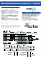
REGISTRATION CARD FOR NEC TECHNOLOGIES PROJECTORS
THANK YOU
Thank you for your purchase of an NEC Technologies
projector. By purchasing an NEC projector, you are
able to access the best limited warranty and service
programs available in the industry today.
InstaCare® service provides for the repair and return of
your projector within three business days. For the ultimate
in hassle free service, NEC pays for the round-trip
shipping.
Register your projector!!
In order to qualify for the One Business Day
replacement coverage portion of InstaCare :
Visit our website at www.nectech.com, click on
product registration, then on presentation products and
submit your completed form online, or return this
completed registration card.
When time matters most and overnight replacement is
SM
not fast enough, InstaCare Xpress, available for a
nominal fee, provides for a “next available flight”
replacement option*.
SM
TravelCare allows projector customers to receive
service on their projector when traveling internationally,
regardless of where the projector was originally
purchased.
Upon receipt, we’ll send a confirmation letter
with all the details you'll need to take advantage
of fast, reliable warranty and service programs from the
company that provides:
Solutions with Vision, NEC Technologies.
With a full compliment of warranty and service
programs from NEC, you’ll never be stranded at
work or on the road!
NEC Technologies, the NEC Technologies Spirit icon and InstaCare are registered trademarks, and InstaCare Xpress and
TravelCare are service marks of NEC Technologies Inc. NEC is a registered trademark of NEC Corporation. SMARTer
Kids is a trademark of the SMARTer Kids Foundation. DLP is a trademark of Texas Instruments Inc. GT Series projectors
are covered by InstaCare three-day repair/return service only. InstaCare and InstaCare Xpress service is available only
in the U.S. and Canada. *Airline restrictions and flight availability may apply for InstaCare Xpress service.
Mr.
Ms.
First Name
Mrs.
Initial
Last Name
Title
Company Name
Street Address
Apt. #
City
St./Prv. Zip+4/Postal Code
Day Phone
E-Mail
-
AREA CODE
Please indicate which product was purchased
Model #
Date of Purchase
MONTH
DAY
Serial #
YEAR
Which segment most closely identifies the market that you will use the product in
Corporate
Government
State
Federal
Education
Local
K-12
Other
Higher Ed
Fill in Blank
TM
If your market segment is Education, did you purchase through the SMARTer Kids Foundation?
Yes
No
Please indicate the # of employees at your company
Yes
E-Mail
No
Mail
<100
100-999
>1000
Can we contact you about new
product offerings in the future? via
What types of products do you currently use and what products are you interested in within the next 12 months?
Currently Use Interested
LCD Projectors
DLP Projectors
High Light Output Projectors
CRT Projectors
Home Theatre
TM
Currently Use Interested
Plasma Monitors
CRT Monitors
Check this
Handheld Computers
box if you do not
want
to receive
Notebook Computers
special offers
Desktop Computers
from carefully
Single/Multi CPU Servers
selected vendors.
LIMITED WARRANTY (USA and Canada only)
NEC SOLUTIONS’ PROJECTOR PRODUCTS
HOW YOU CAN GET WARRANTY SERVICE
NEC Solutions (America), Inc. (hereafter NEC Solutions) warrants
this product to be free from defects in material and workmanship
under the following terms.
1. To obtain service on your product, consult the dealer from whom
you purchased the product.
2. Whenever warranty service is required, the original dated invoice
(or a copy) must be presented as proof of warranty coverage. In
order to obtain warranty service, you may be required to describe
and demonstrate the problem to your dealer or to NEC Solutions.
3. All products returned to NEC Solutions for service MUST have
prior approval. To receive approval or for the name of the
nearest NEC Solutions authorized service center, call NEC
Solutions at 800-836-0655.
4. It shall be your obligation and expense to ship the product,
freight prepaid, or to deliver it to a NEC Solutions authorized
service center, in either the original package or a similar package affording an equal degree of protection.
5. In the event a product is returned to NEC Solutions for warranty
service, and it is determined that there is no product defect or that
the product condition is not covered by this limited warranty, a
diagnostic service fee may be charged to the customer.
HOW LONG IS THE WARRANTY
NEC Solutions’ LT150Z projectors are covered by a three (3)
year limited parts and labor warranty from the date of the first
customer purchase. The lamp when used under normal operating conditions is warranted for 1000 hours or six months,
whichever comes first.
WHO IS PROTECTED
This warranty may be enforced only by the first purchaser, and is
not transferable.
WHAT IS COVERED AND WHAT IS NOT COVERED
Except as specified below, this warranty covers all defects in
material or workmanship in this product.
NEC SOLUTIONS’ LIABILITY FOR ANY DEFECTIVE PRODUCT IS
LIMITED TO THE REPAIR OR REPLACEMENT OF THE PRODUCT
AT NEC SOLUTIONS’ OPTION. REPLACEMENT PRODUCTS MAY
BE NEW OR ‘LIKE NEW’. The following are not covered by the
limited warranty and NEC Solutions shall not be liable for:
1. Any product which is not distributed in the U.S.A. or Canada
by NEC Solutions or which is not purchased, installed, and
operated in the U.S.A or Canada.
2. Any product on which the serial number has been defaced,
modified or removed.
3. Normal decrease in lamp light output over time.
4. Damage, deterioration or malfunction resulting from:
a. Accident, misuse, abuse, neglect, improper ventilation, fire,
dust, smoke, water, lightning or other acts of nature, unauthorized product modification, or failure to follow instructions supplied with the product.
b. Repair or attempted repair by anyone other than a NEC
Solutions authorized service center.
c. Any shipment of the product (claims must be presented to
the carrier).
d. Removal or installation of the product.
e. Any other cause which does not relate to a product defect.
f. Use of the product beyond normal operating conditions.
Normal operating conditions are defined as product use
not in excess of 5 hours per day and 260 days per year.
5. Cartons, carrying cases, shipping cases, batteries, external
cabinets, magnetic tapes, or any accessories used in connection with the product.
6. Service required as a result of third party components.
WHAT NEC SOLUTIONS WILL PAY FOR
NEC Solutions will pay labor and material expenses for covered
items, but NEC Solutions will not pay for the following:
1. Removal or installation charges.
2. Costs of technical adjustments, set-up, maintenance, or adjustment of user controls.
3. Payment of shipping and related charges incurred in returning
the product for warranty repair.
LIMITATION OF IMPLIED WARRANTIES
EXCEPT AS EXPRESSLY SET FORTH IN THIS LIMITED WARRANTY,
NEC SOLUTIONS MAKES NO OTHER WARRANTIES, EXPRESS
OR IMPLIED, INCLUDING BUT NOT LIMITED TO ANY IMPLIED
WARRANTIES OR CONDITIONS OF MERCHANTABILITY AND
FITNESS FOR A PARTICULAR PURPOSE. ANY IMPLIED WARRANTIES THAT MAY BE IMPOSED BY LAW ARE LIMITED TO THE TERMS
AND DURATION OF THIS LIMITED WARRANTY.
EXCLUSION OF DAMAGES
NEC SOLUTIONS’ LIABILITY FOR ANY DEFECTIVE PRODUCT IS
LIMITED TO THE REPAIR OR REPLACEMENT OF THE PRODUCT
AT NEC SOLUTIONS’ OPTION. NEC SOLUTIONS SHALL NOT
BE LIABLE FOR:
1. DAMAGE TO OTHER PROPERTY CAUSED BY ANY DEFECTS
IN THIS PRODUCT, DAMAGES BASED UPON INCONVENIENCE, LOSS OF USE OF THE PRODUCT, LOSS OF TIME,
COMMERCIAL LOSS; OR
2. ANY OTHER DAMAGES, WHETHER INCIDENTAL, CONSEQUENTIAL OR OTHERWISE.
HOW STATE LAW RELATES TO THE WARRANTY
SOME STATES DO NOT ALLOW LIMITATIONS ON HOW LONG
AN IMPLIED WARRANTY LASTS AND/OR DO NOT ALLOW THE
EXCLUSION OR LIMITATION OF INCIDENTAL OR CONSEQUENTIAL DAMAGES, SO THE ABOVE LIMITATIONS AND EXCLUSIONS MAY NOT APPLY TO YOU. THIS LIMITED WARRANTY
GIVES YOU SPECIFIC LEGAL RIGHTS, AND YOU MAY HAVE
OTHER RIGHTS WHICH VARY FROM STATE TO STATE.
FOR MORE INFORMATION, CONTACT:
NEC SOLUTIONS (AMERICA), INC.
1250 N. Arlington Heights Road, Suite 500
Itasca, Illinois 60143-1248
TELEPHONE 800-836-0655
www.necvisualsystems.com
Customers are cautioned that product performance is affected by
system configuration, software, the application, customer data,
and operator control, among other factors. While NEC Solutions’
products are considered to be compatible with many systems, the
specific functional implementation by the customers of the product may vary. Therefore, the suitability of a product for a specific
purpose or application must be determined by the customer and
is not warranted by NEC Solutions.
Printed in Japan
'
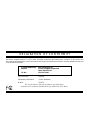
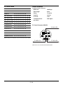
DECLARATION OF CONFORMITY
This device complies with Part 15 of FCC Rules. Operation is subject to the following two conditions. (1) This device may
not cause harmful interference, and (2) this device must accept any interference received, including interference that may
cause undesired operation.
U.S. Responsible Party:
Address:
Tel. No.:
NEC Technologies, Inc.
1250 N. Arlington Heights Road
Itasca, Illinois 60143
(630) 467-5000
Type of Product:
Projector
Equipment Classification:
Class B Peripheral
Models:
LT150Z
We hereby declare that the equipment specified above
conforms to the technical standards as specified in the FCC Rules.
Micro-Portable Projector
LT150Z
English
User’s Manual
Deutsch
Français
Italiano
Español
Svenska
IMPORTANT INFORMATION
Precautions
CAUTION
Please read this manual carefully before using your NEC
LT150Z Projector and keep the manual handy for future reference.
Your serial number is located on the bottom of your
LT150Z. Record it here:
This label is on the side of the remote control.
RF Interference
CAUTION
To turn off main power, be sure to remove
the plug from power outlet.
The power outlet socket should be installed
as near to the equipment as possible, and
should be easily accessible.
WARNING
The Federal Communications Commission does not
allow any modifications or changes to the unit EXCEPT those specified by NEC Technologies in this
manual. Failure to comply with this government regulation could void your right to operate this equipment.
This equipment has been tested and found to comply with the limits for a Class B digital device, pursuant to Part 15 of the FCC Rules. These limits are
designed to provide reasonable protection against
harmful interference in a residential installation. This
equipment generates, uses, and can radiate radio
frequency energy and, if not installed and used in
accordance with the instructions, may cause harmful interference to radio communications. However,
there is no guarantee that interference will not occur
in a particular installation. If this equipment does
cause harmful interference to radio or television reception, which can be determined by turning the
equipment off and on, the user is encouraged to try
to correct the interference by one or more of the following measures:
CAUTION
TO PREVENT SHOCK, DO NOT OPEN
THE CABINET.
NO USER-SERVICEABLE PARTS INSIDE.
REFER SERVICING TO QUALIFIED NEC
SERVICE PERSONNEL.
This symbol warns the user that uninsulated
voltage within the unit may be sufficient to
cause electrical shock. Therefore, it is dangerous to make any kind of contact with any
part inside of the unit.
This symbol alerts the user that important
information concerning the operation and
maintenance of this unit has been provided.
The information should be read carefully to
avoid problems.
• Reorient or relocate the receiving antenna.
• Increase the separation between the equipment and
receiver.
• Connect the equipment into an outlet on a circuit
different from that to which the receiver is connected.
• Consult the dealer or an experienced radio / TV
technician for help.
WARNING
TO PREVENT FIRE OR SHOCK, DO NOT EXPOSE
THIS UNIT TO RAIN OR MOISTURE.
DO NOT USE THIS UNIT’S GROUNDED PLUG
WITH AN EXTENSION CORD OR IN AN OUTLET
UNLESS ALL THREE PRONGS CAN BE FULLY
INSERTED.
DO NOT OPEN THE CABINET. THERE ARE HIGHVOLTAGE COMPONENTS INSIDE. ALL SERVICING MUST BE DONE BY QUALIFIED NEC SERVICE PERSONNEL.
In UK, a BS approved power cable with moulded plug
has a Black (five Amps) fuse installed for use with this
equipment. If a power cable is not supplied with this
equipment please contact your supplier.
DOC Compliance Notice
This Class B digital apparatus meets all requirements
of the Canadian Interference-Causing Equipment Regulations.
3. GSGV Acoustic Noise Information Ordinance:
The sound pressure level is less than 70 dB (A) according to ISO 3744 or ISO 7779.
•
•
•
E–2
IBM is a registered trademark of International Business Machines
Corporation.
Macintosh and PowerBook are registered trademarks of Apple Computer, Inc.
Other product and company names mentioned in this user's manual
may be the trademarks of their respective holders.
Important Safeguards
CAUTION
These safety instructions are to ensure the long life of
your projector and to prevent fire and shock. Please
read them carefully and heed all warnings.
Do not unplug the power cable from the wall outlet under any
one of the following circumstances. Doing so can cause damage
to the projector:
Installation
* While the Hour Glass icon appears.
* While the message "Please wait a moment." appears. This
message will be displayed after the projector is turned off.
* Immediately after the power cable is plugged into the wall
outlet (the POWER indicator has not changed to a steady orange glow).
* Immediately after the cooling fan stops working (The cooling fan continues to work for 90 seconds after the projector is
turned off with the POWER button).
* While the POWER and the STATUS indicators are alternately
flashing.
1. For best results, use your projector in a darkened room.
2. Place the projector on a flat, level surface in a dry area
away from dust and moisture.
3. Do not place your projector in direct sunlight, near heaters
or heat radiating appliances.
4. Exposure to direct sunlight, smoke or steam can harm internal components.
5. Handle your projector carefully. Dropping or jarring can damage internal components.
6. Do not place heavy objects on top of the projector.
7. If you wish to have the projector installed on the ceiling:
a. Do not attempt to install the projector yourself.
b. The projector must be installed by qualified technicians
in order to ensure proper operation and reduce the risk
of bodily injury.
c. In addition, the ceiling must be strong enough to support the projector and the installation must be in accordance with any local building codes.
d. Please consult your dealer for more information.
Power Supply
1. The projector is designed to operate on a power supply of
100-120 or 200-240 V 50/60 Hz AC. Ensure that your power
supply fits this requirement before attempting to use your
projector.
2. Handle the power cable carefully and avoid excessive bending. A damaged cord can cause electric shock or fire.
3. If the projector is not to be used for an extended period of
time, disconnect the plug from the power outlet.
E–3
Cleaning
1. Unplug the projector before cleaning.
2. Clean the cabinet periodically with a damp cloth. If heavily
soiled, use a mild detergent. Never use strong detergents
or solvents such as alcohol or thinner.
3. Use a blower or lens paper to clean the lens, and be careful not to scratch or mar the lens.
Lamp Replacement
•
To replace the lamp, follow all instructions provided on page
E-49.
•
Be sure to replace the lamp when the message "The lamp
has reached the end of its usable life. Please replace
the lamp.!!" appears. If you continue to use the lamp after
the lamp has reached the end of its usable life, the lamp
bulb may shatter, and pieces of glass may be scattered in
the lamp case. Do not touch them as the pieces of glass
may cause injury. If this happens, contact your NEC dealer
for lamp replacement.
•
Allow a minimum of 90 seconds to elapse after turning off
the projector. Then disconnect the power cable and allow
60 minutes to cool the projector before replacing the lamp.
Fire and Shock Precautions
1. Ensure that there is sufficient ventilation and that vents are
unobstructed to prevent the build-up of heat inside your
projector. Allow at least 3 inches (10 cm) of space between
your projector and a wall.
2. Prevent foreign objects such as paper clips and bits of paper from falling into your projector. Do not attempt to retrieve any objects that might fall into your projector. Do not
insert any metal objects such as a wire or screwdriver into
your projector. If something should fall into your projector,
disconnect it immediately and have the object removed by
a qualified NEC service personnel.
3. Do not place any liquids on top of your projector.
•
Do not look into the lens while the projector is on. Serious
damage to your eyes could result.
•
Keep any items such as magnifying glass out of the light
path of the projector. The light being projected from the
lens is extensive, therefore any kind of abnormal objects
that can redirect light coming out of the lens, can cause
unpredictable outcome such as fire or injury to the eyes.
•
Do not cover the lens with the supplied lens cap or equivalent while the projector is on. Doing so can lead to melting
of the cap and possibly burning your hands due to the heat
emitted from the light output.
•
Do not look into the laser pointer while it is on and do not
point the laser beam at another person.Serious injury could
result.
E–4
TABLE OF CONTENTS
1. INTRODUCTION
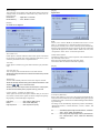
Setup ......................................................................... E-37
Orientation ........................................................... E-37
Cinema Position ................................................... E-37
Background .......................................................... E-37
Mouse Settings .................................................... E-38
PC Card Viewer Options ...................................... E-38
Show Folder List ............................................. E-38
Auto Play ......................................................... E-38
Auto Play Interval ............................................ E-38
Manual Play .................................................... E-38
Capture Options ................................................... E-38
Signal Select ........................................................ E-38
RGB ................................................................ E-38
Video and S-Video .......................................... E-38
Auto Adjust (RGB only) ........................................ E-38
Auto Start ............................................................. E-39
Power Management ............................................. E-39
Power Off Confirmation ........................................ E-39
Keystone Save ..................................................... E-39
White Segment .................................................... E-39
Clear Lamp Hour Meter ....................................... E-39
Communication Speed ........................................ E-39
Default Source Select .......................................... E-39
Control Panel Key Lock ........................................ E-39
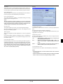
Introduction to the LT150Z Projector ........................... E-6
Getting Started ............................................................ E-6
What’s in the Box ........................................................ E-7
Getting to Know Your LT150Z Projector ...................... E-8
Front / Side Features ............................................. E-8
Attaching the lens cap ........................................... E-8
Rear / Side Features .............................................. E-9
Top Features ........................................................ E-10
Terminal Panel Features ...................................... E-11
Remote Control Features ..................................... E-12
Operating Range ............................................ E-14
Remote Control Battery Installation ................ E-14
Setting the function switch .............................. E-14
Remote Control Precautions ........................... E-14
Using Remote Mouse Receiver ...................... E-15
Switching Operation mode between
computer and projector ............................... E-16
2. INSTALLATION
Setting Up Your Projector .......................................... E-17
Selecting a Location .................................................. E-17
Screen and Projection Distance ................................ E-17
Distance Chart .......................................................... E-18
Reflecting the Image ................................................. E-18
Wiring Diagram ......................................................... E-19
Connecting Your PC or Macintosh Computer ...... E-20
Connecting Your DVD Player ............................... E-21
Connecting Your VCR or Laser Disc Player ......... E-22
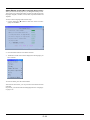
About Startup screen
(Menu Language Select screen) ........................... E-23
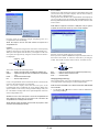
Tools .......................................................................... E-40
Capture ................................................................ E-40
PC Card Files ...................................................... E-40
Changing Background Logo ........................... E-40
Chalk Board ......................................................... E-41
Help ........................................................................... E-41
Contents .............................................................. E-41
Information ........................................................... E-41
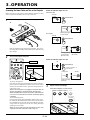
3. OPERATION
Connecting the Power Cable, Turn on the Projector
and Adjust Projected image .................................... E-24
Basic Operation ........................................................ E-27
Using the Menus ....................................................... E-29
Using a USB Mouse .................................................. E-30
Menu Tree ................................................................. E-31
Menu Elements ......................................................... E-32
Menu Descriptions & Functions ................................ E-33
Source Select ............................................................ E-33
RGB/Video/S-Video/PC Card Viewer
Picture ....................................................................... E-33
Brightness/Contrast/Color/Hue/Sharpness
Volume ...................................................................... E-33
Image Options ........................................................... E-34
Keystone .............................................................. E-34
Lamp Mode .......................................................... E-34
Aspect Ratio ........................................................ E-34
Noise Reduction .................................................. E-35
Position/Clock ...................................................... E-35
Resolution ............................................................ E-35
Video Filter ........................................................... E-35
Factory Default ..................................................... E-35
Color Management ................................................... E-36
Gamma Correction .............................................. E-36
Color Matrix ......................................................... E-36
White Balance ...................................................... E-36
Projector Options ...................................................... E-36
Menu .................................................................... E-36
Menu Mode ..................................................... E-36
Advanced Menu, Basic/Custom Menu
Language ............................................................. E-36
Projector Pointer .................................................. E-37
Menu Display Time .............................................. E-37
Message (Source Display, No Input) .................... E-37
Direct Button (Volume Bar, Keystone Bar) ........... E-37
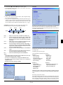
Using the PC Card Viewer Function ......................... E-42
Features ............................................................... E-42
Inserting and Ejecting a CompactFlash™ Card .. E-42
Installing the PC Card Viewer Software ............... E-43
Starting Up the PC Card Viewer Software on
your PC (PC Card Viewer Utility 1.0) ............... E-43
Operating the PC Card Viewer Function
from the Projector (playback) ........................... E-44
Capturing Images Displayed on the Projector ..... E-46
Viewing Digital Images ......................................... E-47
Uninstalling the PC Card Viewer Software ........... E-47
Terminology ......................................................... E-48
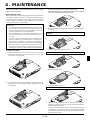
4. MAINTENANCE
Replacing the Lamp .................................................. E-49
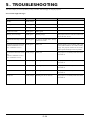
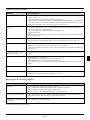
5. TROUBLESHOOTING
Power / Status Light Messages ................................. E-50
Common Problems & Solutions ................................ E-51
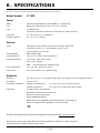
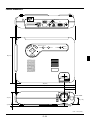
6. SPECIFICATIONS
Optical/Electrical/Mechanical .................................... E-52
Cabinet Dimensions .................................................. E-53
D-Sub Pin Assignments ............................................ E-54
Compatible Input Signal List ..................................... E-55
PC Control Codes ..................................................... E-56
Cable Connection ..................................................... E-56
CompactFlash is a trademark of San Disk Corporation.
E–5
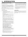
1. INTRODUCTION
Introduction to the LT150Z Projector
This section introduces you to your new LT150Z Projector and describes the features and controls.
Congratulations on Your Purchase of The LT150Z Projector
The LT150Z is one of the very best projectors available today. The
LT150Z enables you to project precise images up to 200 inches across
(measured diagonally) from your PC or Macintosh computer (desktop or notebook), VCR, DVD player, document camera, a laser disc
player or PC Card Viewer.
You can use the projector on a tabletop or cart, you can use the projector to project images from behind the screen, and the projector
can be permanently mounted on a ceiling*1. The remote control can
be used wirelessly.
*1 Do not attempt to mount the projector on a ceiling yourself.
The projector must be installed by qualified technicians in order
to ensure proper operation and reduce the risk of bodily injury.
In addition, the ceiling must be strong enough to support the
projector and the installation must be in accordance with any
local building codes. Please consult your dealer for more information.
*2 An UXGA (16001200) and SXGA image (12801024) are
displayed with NEC Technologies Advanced AccuBlend.
*3 The PC Control Utility 1.0 is required. This program is included
on the supplied CD-ROM.
*4 The USB terminal meets the USB1.1 specification and accepts
a USB mouse only.
Getting Started
Features you’ll enjoy:
• Simple set up and operation.
• A high-performance 135 watt NSH lamp.
• The supplied wireless remote control that operates the projector from the front or rear.
• The image can be projected between 30 and 200 inches (measured diagonally).
• Keystone correction allows you to correct trapezoidal distortion so that the image is square.
• You can choose between video modes depending on your source:
"normal" for a typical picture, "natural" for true color reproduction.
• The built-in PC Card Viewer allows you to start your presentation even when a PC is not available at the site.
• The "Capture" enables you to capture the current projected image.
• An image can be projected from in front or behind a screen,
and the projector can even be installed on the ceiling.
• NEC Technologies’ exclusive Advanced AccuBlend intelligent
pixel blending technology - an extremely accurate image compression technology - offers a crisp image with UXGA (1600
1200) resolution*2.
• Supports most IBM VGA, SVGA, XGA , SXGA/UXGA(with
Advanced AccuBlend)*2, Macintosh, component signal (YCbCr
/ YPbPr) or any other RGB signals within a horizontal frequency
range of 15 to 100 kHz and a vertical frequency range of 50 to
120 Hz. This includes NTSC, PAL, PAL-N, PAL-M, PAL60,
SECAM and NTSC4.43 standard video signals.
The fastest way to get started is to take your time and do everything
right the first time. Take a few minutes now to review the user’s
manual. This may save you time later on. At the beginning of each
section of the manual you’ll find an overview. If the section doesn’t
apply, you can skip it.
NOTE: Composite video standards are as follows:
NTSC: U.S. TV standard for video in U.S. and Canada.
PAL: TV standard used in Western Europe.
PAL-N: TV standard used in Argentine, Paraguay and Uruguay.
PAL-M: TV standard used in Brazil.
PAL60: TV standard used for NTSC playback on PAL TVs.
SECAM: TV standard used in France and Eastern Europe.
NTSC4.43: TV standard used in Middle East countries.
• The supplied remote control can be used without a cable, and
you can even use the remote control and mouse adapter to operate your PC or Macintosh mouse wirelessly from across the
room with the built-in remote mouse receiver.
• You can control the projector with a PC using the PC Control
port*3.
• USB terminal allows USB mouse operation *4.
• The contemporary cabinet design is light, compact, easy to carry,
and complements any office, boardroom or auditorium.
• Eight pointers are available for your presentation.
E–6
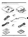
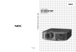
What's in the Box?
Make sure your box contains everything listed. If any pieces are missing, contact your dealer.
Please save the original box and packing materials if you ever need to ship your LT150Z Projector.
EN T ER
CAN
CEL
LE
CT
SE
N
U
PC
CA
A
RD
AD UTO
JU
AC
ST
CE
SS
ME
SO
UR
CE
O
ST N /
AN
DB
Y
ST
AT
PO
US
WE
R
Projector
Lens cap
Soft carrying case
FF
O
EO
VID
ER
W
PO
J.
EO
AD
ID
TO
AU
S-V
N
B1
G
O
R
Batteries
B2
G
R
R
SE
LA
SE
LE
CT
PJ
FO
HEL
KEYS
FREE
PIC-
MUT
TONE
P
MAG
CU
S
POIN
ZO
OM
SH
TER
NIFY
PC
IFT
CARD
SLID
E
ZE
VO
L.
E
FOLD
SLID
String and rivet
ER
E
LIST
Remote control
Remote mouse receiver
Power cable
PS/2 adapter
RGB signal cable
ck t
ui ec
Q nn de
o i
C Gu
r's l
se a
U anu
M
CD-ROM
E–7
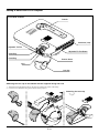
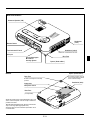
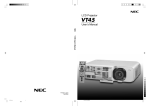
Getting to Know Your LT150Z Projector
Front/ Side Features
Controls
ENTER
PC
A
AD UTO
JU
ST
CT
LE
SE
U
S
ES
CC
DA
CA
R
NCEL
N
CA
ME
CE
UR
SO
Y
O
ST N /
AN
DB
ST
AT
US
WE
R
PO
Ventilation (inlet)
Adjustable Tilt Foot
Adjustable Tilt Foot Button
Zoom Ring
Focus Ring
Remote Sensor
Lens
Lens Cap
Attaching the lens cap to the bottom with the supplied string and rivet
○ ○ ○ ○ ○ ○ ○ ○ ○ ○ ○ ○ ○ ○ ○ ○ ○ ○ ○ ○ ○ ○ ○ ○
○ ○ ○ ○ ○ ○ ○ ○ ○ ○ ○ ○ ○ ○ ○ ○ ○ ○ ○ ○ ○ ○ ○ ○
1. Thread the string through the hole on the lens cap and then tie a knot in the string.
2. Use the rivet to attach the string to the bottom of the projector.
E–8
Attaching the lens cap
Rear/ Side Features
Monaural Speaker (1W)
S
P
TU
TA
S
O
W
E
R
/ D
N N
O TA
S
B
Y
S
O
U
R
C
E
AU
C
P
DIO
A
ME
N
R
T
TO S
U U
A DJ
A
S
S
E
C
C
A
D
C
U
S
RG
T
O
C
IDE
CO
LE
S-V
PC
E
ENTER
B
CA
NT
RO
L
Ventilation
(inlet)
NCEL
VID
EO
Remote Sensor
US
B
PC
CA
RD
AC
IN
Ventilation (outlet)
Terminals and PC card
Heated air is exhausted from here
AC Input
Rear Foot
Slot for Kensington
MicroSaver
Security System
Spacer (black rubber)
Bottom
Spacer (black rubber)
Rear Foot
To fine-adjust the height of the rear
foot, remove the spacer and rotate the
rear foot to the desired height.
Rotate to fine-adjust horizontally
position
Ventilation (inlet)
Lamp cover
Lamp cover screw
Rear Foot
(not adjustable)
NOTE: The projector has an internal temperature sensor. The
sensor controls the speed of the fan to keep constant temperature in the inside.
When the internal temperature rises, the built-in fan automatically runs at a high speed (high-speed mode).
During this time, the sound of exhaust may be heard. This is
not a malfunction.
E–9
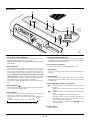
Top Features
2
S
TA
TU
P
S
O
W
E
R
/ D
N N
O TA
S
4
B
Y
S
O
U
R
C
9
E
3
10
5
1
P
AU
DIO
C
A
A
U
D
N
R
T
TO S
U U
A J
D
A
S
S
E
C
C
C
ME
T
C
S-V
IDE
O
PC
CO
NT
RO
L
LE
ENTER
E
S
RG
B
CA
7
US
B
PC
CA
RD
1. Power Button (ON / STAND BY)
Use this button to turn the power on and off when the power is
supplied and the projector is in standby mode.
NOTE: To turn off the projector, press and hold this button for a minimum
of two seconds.
2. Status Indicator
When this is lit red continually, it's warning you that the projection lamp has exceeded 1000 hours (1500 hours in Eco mode) of
service. After this light appears, it is advisable to replace the projection lamp as soon as possible. (See page E-49). In addition the
message "The lamp has reached the end of its usable life. Please
replace the lamp!!." appears continually until the lamp is replaced.
If this light blinks red rapidly, it indicates that the lamp cover is
not attached properly or the projector is overheated.
See the Power/Status Light Messages on page E-50 for more details.
3. Power Indicator ( )
When this indicator is green, the projector is on; when the indicator is orange, it is in standby mode.
4. Source Button
Use this button to select a video source such as a PC, VCR, DVD
player or PC Card Viewer (CompactFlash card).
Each time this button is pressed, the input source will change as
follows:
→ RGB → Video → S-Video → PC Card Viewer
If no input signal is present, the input will be skipped.
NCEL
6
VID
EO
8
5. Auto Adjust Button (RGB only)
Use this button to adjust Position-H/V and Pixel Clock/Phase for
an optimal picture. Some signals may not be displayed correctly
or take time to switch between sources.
6. PC Card Access Indicator
Lights while accessing a CompactFlash memory card.
7. Enter Button
Executes your menu selection and activates items selected from
the menu.
8. Cancel Button
Press this button to exit "Menus". Press this button to return the
adjustments to the last condition while you are in the adjustment
or setting menu.
9. Select (▲▼ ) / Volume (+) (–) Buttons
▲▼: Use these buttons to select the menu of the item you wish
to adjust.
When no menus appear, these buttons work as a volume
control.
: Use these buttons to change the level of a selected menu
item.
A press of the button executes the selection.
When the menus or the Viewer tool bar is not displayed,
these buttons can be used to select a slide, or to move the
cursor in Folder List or Slide List.
When the pointer is displayed, these ▲▼ buttons
move the pointer.
10. Menu Button
Displays the menu.
E–10
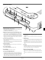
Terminal Panel Features
TU
P
S
O
W
1
E
R
/ D
N N
O TA
S
2
B
Y
S
3
O
U
R
C
E
4
P
AU
DIO
C
A
A
U
D
N
R
T
TO S
U U
A DJ
A
S
S
E
C
C
C
ME
ENTER
5
S-V
IDE
O
PC
CO
NT
RO
L
T
C
LE
E
S
RG
B
CA
6
VID
EO
US
B
7
NCEL
PC
CA
RD
AC
8
1. Audio Input Mini Jack (3.5 mm ∅)
This is where you connect audio output from your computer, VCR,
DVD player or laser disc player.
A commercially available audio cable is required.
9
10
2. RGB Input/ Component Input Connector (Mini D-Sub 15 pin)
Connect your PC or other RGB equipment such as IBM or compatible computers. Use the supplied RGB cable to connect to a
PC. Or connect a Macintosh computer here using the supplied
RGB cable. This also serves as a component input connector that
allows you to connect a component video output of component
equipment such as a DVD player.
3. S-Video Input (Mini DIN 4 Pin)
Here is where you connect the S-Video input from an external
source like a VCR.
NOTE: S-Video provides more vivid color and higher resolution than the
traditional composite video format.
4. Video Input (RCA)
Connect a VCR, DVD player, laser disc player, or document camera here to project video.
5. PC Card Eject Button
Press to eject a CompactFlash memory card.
6. PC Card Slot
Insert a CompactFlash memory card here.
7. PC Control Port (Mini DIN 8 Pin)
Use this port to connect your PC to control your projector via a
serial cable. This enables you to use your PC and serial communication protocol to control the projector. The NEC optional serial
cable is required to use this port. Also PC Control Utility 1.0 included in the supplied CD-ROM must be installed on your PC.
IN
If you are writing your own program, typical PC control codes are
on page E-56.
A cap is put on the port at the factory. Remove the cap when using
the port.
8. USB Terminal
Connect a commercially available mouse that supports USB. You
can operate the menu or PC Card Viewer with the USB mouse via
this terminal.
Note that this terminal is not used with a computer and that there
may be some brands of USB mouse that the projector does not
support.
9 AC Input
Connect the supplied power cable's three-pin plug here. When you
plug the other end into an active wall outlet, the POWER indicator turns orange and the projector is in standby mode.
10 Built-in Security Slot ( )
This security slot supports the MicroSaver® Security System.
MicroSaver® is a registered trademark of Kensington Microware
Inc.
The logo is trademarked and owned by Kensington Microware
Inc.
E–11
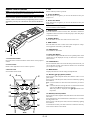
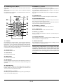
Remote Control Features
NOTE: If you are using a Macintosh computer, you can click either the
right-click or left-click button to activate the mouse.
5. Power ON Button
If the main power is applied, you can use this button to turn your
projector on.
6. Power OFF Button
If the main power is applied, you can use this button to turn your
projector off.
NOTE: To turn off the projector, press and hold the POWER OFF button for a minimum of two seconds.
PI
C
-M
U
TE
ZE
EE
M
NE
TE
P
J
KE
S
U
C
FO
LP
E
H
YS
TO
PO
IN
M
O
ZO
7. VIDEO Button
Press this button to select an NTSC, PAL, SECAM or NTSC4.43
compatible video source from a VCR, DVD player, laser disc player
or document camera.
FR
AG
N
R
T
IF
H
S
PC
IF
C
Y
AR
D
E
D
LI
S
L.
O
V
FO
LD
ER
SL
ID
E
T
S
LI
NOTE: If any one of the buttons is pressed and held for 60 seconds or
more, the button operations will cease to operate. This is not a malfunction, rather it is a feature used to prolong battery power. To cancel
this feature, press any one of the buttons other than the SELECT button.
4. LED
Flashes when any button is pressed.
CT
LE
SE
8. S-VIDEO Button
Press this button to select an S-Video source from a VCR.
LAS
ER
RG
B2
AUT
O
9. RGB 1 Button
Press this button to select a video source from computer or component equipment connected to your RGB port.
RG
B1
ADJ.
VID
EO
S-V
IDE
O
PO
WE
R
ON
OF
F
10. RGB 2 Button
Not available on this model.
3
1
2
1. Infrared Transmitter
Direct the remote control toward the remote sensor on the projector
cabinet.
11. AUTO ADJ Button
Use this button to adjust an RGB source for an optimal picture. Some
signals may not be displayed correctly or take time to switch between sources.
2. Laser Pointer
Beams a laser light when "Laser" button is pressed.
12. LASER Button
Press and hold this button to activate the laser pointer. When lit, you
can use the laser to draw your audience's attention to a red dot that
you can place on any object.
3. Remote Jack
Not available on this model.
13. MENU Button
Displays the menu for various settings and adjustments.
6
4
5
ON
OFF
8
7
POWER
VIDEO
S-VIDEO
RGB1
AUTO ADJ.
RGB2
9
10
LASER
11
12
MENU
13
14
15
EN
L
SELECT
TE
N
CA
R
CE
16
14. SELECT (▲▼ ) (Mouse) Button
When you are in the Computer mode, these buttons work as a computer mouse.
When you are in the Projector mode, which is indicated by lighting
the PJ button:
▲▼: Use these buttons to select the menu of the item you wish to
adjust.
: Use these buttons to change the level of a selected menu item.
A press of the button executes the selection.
When the pointer is displayed, these ▲▼ buttons move
the pointer.
15. ENTER (Left Click) Button
When you are in the Computer mode, this button works as the mouse
left button.
When this button is pressed and held for a minimum of 1.5 seconds,
the drag mode is set.
When you are in the Projector mode, which is indicated by lighting
the PJ button:
Use this button to enter your menu selection. It works the same way
as the "Enter" button on the cabinet.
PJ
E–12
16. CANCEL (Right Click) Button
When you are in the Computer mode, this button works as the mouse
right button.
When you are in the Projector mode, which is indicated by lighting
the PJ button:
Press this button to exit "Menus". It works the same way as the “Cancel” button on the cabinet.
22
FOCUS
18
21
23
24
25
26
27
ZOOM
25. FREEZE Button
This button will freeze a picture. Press again to resume motion.
17
19
PJ
26. PICTURE MUTE Button
This button turns off the image and sound for a short period of time.
Press again to restore the image and sound.
NOTE: When the menu is displayed, a press of this button mutes an
image and sound without turning off the menu.
SHIFT
20
HELP
POINTER PC CARD
KEYSTONE MAGNIFY
FREEZE
PIC-MUTE
24. MAGNIFY (+) (–) Button
Use this button to adjust the image size up to 400%.
When the pointer is displayed, the image is magnified about the center of the pointer. When the pointer is not displayed, the image is
magnified about the center of the screen.
When the image is magnified, the pointer is changed to the magnifying icon.
VOLUME
SLIDE
28
27. VOLUME (+) (–) Button
Press (+) to increase the volume and (–) to decrease it.
29
28. PC CARD Button
Press this button to select the PC Card Viewer source.
30
29. SLIDE (+) (–) Button
Press (+) to select the next folder or slide and (–) to select the previous folder or slide.
FOLDER
SLIDE
31
LIST
30. FOLDER LIST Button
Press this button to select PC Card Viewer source to display a list of
folders included in a CompactFlash card.
17. PJ Button
Press this button to switch the Select, Cancel, and Enter buttons between the Projector mode (lit red) and the Computer mode. Press
this button or any one of the Power ON/OFF, Menu, Help, Pointer,
Magnify, PC Card, Folder List or Slide List buttons to switch to the
Projector mode and the PJ button lights red. To switch back to the
Computer mode, press the PJ button again.
18. FOCUS Button
Not available on this model.
31. SLIDE LIST Button
Press this button to select PC Card Viewer source to display a list of
slides included in a CompactFlash card.
*NOTE: The default is the Computer mode, which allows you to use
the Select, Cancel, and Enter buttons as your computer mouse. When
the POWER ON/OFF, MENU, HELP, POINTER, MAGNIFY, PC CARD,
FOLDER LIST, or SLIDE LIST button is pressed, the PJ button lights
red to indicate that you are in the Projector mode. If no buttons are
pressed within 10 seconds, the light goes out and the Projector mode
is canceled.
19. ZOOM Button
Not available on this model.
20. SHIFT Button
Not available on this model.
21. HELP Button
Provides information about operation and adjustment procedures or
the set information for the current menu or adjustment during menu
operation.
22. POINTER Button
Press this button to display one of the eight pointers; press again to
hide the pointer. You can move your pointer icon to the area you
want on the screen using the Select button.
23. KEYSTONE (+) (–) Button
Press the (+) or (–) button to correct the keystone (trapezoidal) distortion, and make the image square.
E–13
Operating Range
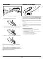
Setting the function switch
7m
7m
30˚
30˚
30˚
30˚
OFF ON
Remote Control Battery Installation
There are two switches on the bottom of the battery case: an applicable projector selector switch (1) and laser enable/disable switch
(2). Check the projector being used and decide whether to enable or
disable laser, then set these switches as necessary using the tip of a
thin ball-point pen.
On this model, an applicable projector selector switch (1) is not used.
1. Press firmly and slide the battery cover off.
2. Remove both old batteries and install new ones (AA). Ensure
that you have the batteries' polarity (+/–) aligned correctly.
Switch (2)
On: Enabled (the laser lights when the LASER button is pressed)
[Factory default]
Off: Disabled (the laser does not light even when the LASER button
is pressed)
Disable the laser when using in an environment in which the unit is
accessible to children.
Remote Control Precautions
• Handle the remote control carefully.
• If the remote control gets wet, wipe it dry immediately.
• Avoid excessive heat and humidity.
• If you will not be using the remote control for a long time, remove the batteries.
• Do not place the batteries upside down.
• Do not look into the laser pointer while it is on.
• Do not point the laser beam at a person.
3. Slip the cover back over the batteries until it snaps into place.
Do not mix different types of batteries or new and old batteries.
Note on Remote Control Operation:
Pressing and holding the Select (▲, ▼, , )/ Mouse button while
installing new batteries may cause malfunction or no operation.
Should this happen, remove the batteries and then install them again
without touching the Select/Mouse button.
E–14
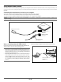
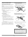
Using Remote Mouse Receiver
The remote mouse receiver enables you to operate your computer’s mouse functions from the remote control (Computer mode). It is
a great convenience for clicking through your computer-generated presentations.To return to the Projector mode, press the PJ button
(lit red).
Connecting the remote mouse receiver to your computer
If you wish to use the remote mouse function, connect the mouse receiver and computer.
The mouse receiver can be connected directly to the computer using the USB terminal.
To connect it to the computer using the mouse (PS/2) terminal, do so using the PS/2 adapter.
NOTE: Depending on the type of connection or OS installed on your computer, you may have to restart your computer or change your
computer settings.
Computer
Remote mouse receiver
To USB port of PC or
Macintosh
To Mouse (PS/2)
port of PC
Atach the supplied
PS/2 Adapter
When connecting using the USB terminal
When operating a computer via the remote mouse receiver
For PC, the mouse receiver can only be used with a Windows 98,
Windows ME or Windows 2000 operating system.
NOTE:
• Wait at least 5 seconds after disconnecting the mouse receiver
before reconnecting it and vice versa. The computer may not
identify the mouse receiver if it is repeatedly connected and
disconnected in rapid intervals.
• When using the PS/2 adapter, be sure to attach the PS/2 adapter
to the remote mouse receiver first. Do not connect or disconnect the USB connector of the remote mouse receiver with
the PS/2 adapter on the mouse (PS/2) port of your PC. Doing
so can result in your PC failing to detect the remote mouse
receiver.
E–15
7m
30˚
30˚
Remote sensor on the
remote mouse
receiver
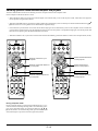
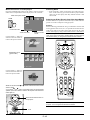
Switching operation mode between computer and projector
The three shaded buttons shown on the drawing work as a computer mouse in the Computer mode.
In the Computer mode the PJ button is not lit.
• When the MENU button is pressed, the PJ button lights red to indicate that you are in the Projector mode, which allows the projector
menu operation using the three buttons.
• When the POINTER button is pressed, the PJ button lights red to indicate that you are in the Projector mode and that the SELECT ▲▼
button works as a moving button for the POINTER or magnified image.
• If no buttons are pressed within 10 seconds, the PJ button's light goes out to indicate that you are in the Computer mode. To enable the
projector menu operation again, press the PJ button to light red. To move the pointer or a magnified image again, turn off the pointer and
then turn on the pointer (press the POINTER button two times).
• When the PJ button is lit, if you want to use the mouse function immediately, press the PJ button to return to the Computer mode (not lit).
OFF
ON
OFF
ON
POWER
VIDEO
S-VIDEO
POWER
RGB1
AUTO ADJ.
RGB2
VIDEO
LASER
AUTO ADJ.
S-VIDEO
MENU
Works as a mouse for your
computer.
R
CA
NC
E
Works as the Select button
on the projector.
SELECT
Works as a right-click button for
your computer.
EN
L
L
SELECT
TE
RGB2
LASER
MENU
EN
RGB1
TE
R
PJ
CA
NC
E
PJ
Lit red
Not lit
FOCUS
HELP
ZOOM
FREEZE
PIC-MUTE
SHIFT
Works as a left-click button for
your computer.
POINTER PC CARD
KEYSTONE MAGNIFY
VOLUME
Works as the Cancel
button on the projector.
FOCUS
HELP
SLIDE
ZOOM
POINTER PC CARD
KEYSTONE MAGNIFY
FOLDER
FREEZE
SLIDE
PIC-MUTE
SHIFT
VOLUME
SLIDE
FOLDER
SLIDE
LIST
LIST
During Computer mode:
During Computer mode by pressing the ENTER button for 1.5 seconds or more then releasing, the drag mode is set and the drag operation can be performed simply by pressing the SELECT (▲, ▼, ,
) (mouse) button. To cancel the drag mode, press the ENTER (left
click) button again or press the CANCEL (right click) button.
E–16
Works as the Enter button
on the projector.
2. INSTALLATION
This section describes how to set up your LT150Z projector and how to connect video and audio sources.
Setting up Your Projector
Your LT150Z Projector is simple to set up and use. But before you get started, you must first:
1. Determine the image size.
2. Set up a screen or select a non-glossy white wall onto which you can project your image.
Ensure that the power cable and any other cables connecting to video sources are disconnected before moving the projector.
When moving the projector or when it is not in use, cover the lens with the lens cap.
Selecting a Location
The further your projector is from the screen or wall, the larger the image. The minimum size the image can be is approximately 30" (0.8 m)
measured diagonally when the projector is roughly 4 feet (1.3 m) from the wall or screen. The largest the image can be is 200" (5.1 m) when
the projector is about 29 feet (8.8 m) from the wall or screen.
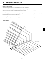
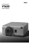
Screen and Projection Distance
The following shows the proper relative positions of the projector and screen. Refer to the table to determine the position of installation.
Throw distance
Scr
ee
406 n size
.4(W
(Un
it:
)X
304 cm /
inc
.8(H
365
) / 1 h)
.8(W
60(
W)
)X
X1
274
20(
.3(H
H)
)/1
44(
W
304
)
X1
.8(W
08(
)X
H)
228
.6(H
)/1
20(
W)
243
X9
.8(W
0(H
)X
)
182
.9(H
203
)/9
.2(W
6(W
)X
)X
150
72(
152
H)
"
.4(H
)/8
162
0(W
.6(W
)X
)X
60(
H)
121
.9(H
120
)/6
"
121
4(W
.9(W
)X
)X
4
8(H
91.
100
)
4(H
"
)/4
81.
3(W
8(W
)X
)X
61.
36(
61.0
80"
0(H
H)
(W)
)/3
X4
2
(
5.7(
W)
H) /
X2
4(H
24(
60"
W)
)
X1
8(H
)
30"
een
200
"
180
"
Unit: m / inch
40"
3
E–17
8.8
/ 34
6
1
/ 31
7.9
0
/ 26
6.6
5.3
/ 20
9
/ 17
4.4
3.5
/ 13
8
2
/ 10
/ 67
/ 51
er
2.6
ent
1.3
sc
1.7
Len
Scr
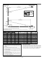
Distance Chart
Lens Center
D
C
Throw Distance
Screen Top
α
B
Lens Offset from Center of Projector
Screen Center
2.97” (75.5mm)
C
Throw Distance
Screen Center
B
Screen Bottom
Lens Center
D
α
1.5”(38mm)
Projector feet
B=Vertical distance between lens center and screen center
D=Vertical distance between lens center and top of screen (bottom of screen for desktop)
NOTE: Distances may vary +/-5%.
Screen Size
Diagonal
Width
inch mm inch mm
30
762
24
610
40 1016 32
813
60 1524 48 1219
67 1702 54 1361
72 1829 58 1463
80 2032 64 1626
84 2134 67 1707
90 2286 72 1829
100 2540 80 2032
120 3048 96 2438
150 3810 120 3048
180 4572 144 3658
200 5080 160 4064
C
B
Height
Wide
inch mm inch mm inch mm –
18
457
12
307
46 1160 –
24
610
16
409
61 1560 –
36
914
24
613
93 2360 –
40 1021 27
685 104 2640 –
43 1097 29
736 112 2850 –
48 1219 32
818 125 3170 –
50 1280 34
859 131 3330 –
54 1372 36
920 141 3570 –
60 1524 40 1022 156 3970 –
72 1829 48 1227 188 4770 –
90 2286 60 1533 235 5980 –
108 2743 72 1840 283 7190 –
120 3048 80 2045 315 7990 –
WARNING
* Installing your projector on the ceiling must be done by a
qualified technician. Contact your NEC dealer for more information.
* Do not attempt to install the projector yourself.
• Only use your projector on a solid, level surface. If the projector falls to the ground, you can be injured and the projector severely damaged.
• Do not use the projector where temperatures vary greatly.
The projector must be used at temperatures between 41˚F
(5˚C) and 95˚F (35˚C).
• Do not expose the projector to moisture, dust, or smoke. This
will harm the screen image.
• Ensure that you have adequate ventilation around your projector so heat can dissipate. Do not cover the vents on the
side or the front of the projector.
Tele
inch mm inch
56 1410
3
75 1900
4
113 2870
6
126 3210
7
136 3450
7
151 3840
8
159 4040
9
170 4330
9
189 4810 10
228 5790 12
285 7240 15
343 8700 18
381 9670 20
C=Throw distance
α=Throw angle
α
D
mm
78
104
156
174
187
208
219
234
260
312
390
469
521
Wide
degree
14.8
14.7
14.6
14.5
14.5
14.5
14.5
14.5
14.4
14.4
14.4
14.4
14.4
–
–
–
–
–
–
–
–
–
–
–
–
–
–
Tele
degree
12.3
12.1
12.1
12.0
12.0
12.0
12.0
12.0
12.0
12.0
12.0
11.9
11.9
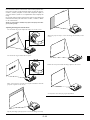
Reflecting the Image
Using a mirror to reflect your projector’s image enables you to enjoy
a much larger image. Contact your NEC dealer if you need a mirror.
If you’re using a mirror and your image is inverted, use the “Menu”
and “Select” buttons on your projector cabinet or ▲▼ buttons on
your remote control to correct the orientation. (See page E-37.)
E–18
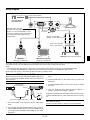
Wiring Diagram
To video, S-video, and audio
inputs on the projector.
VCR, DVD Player or
LaserDisc Player
AUDIO
RGB Signal cable (supplied)
To mini D-Sub 15-pin connector on the
projector. It is recommended that you use a
commercially available distribution amplifier if
connecting a signal cable longer than the
supplied cable.
Document Camera
RGB
S-VIDEO
VIDEO
PC CONTROL
Optional 15-pin-to-RCA
(female)3 cable (ADP-CV1)
Component video cable
RCA3 (not supplied)
DVD Player (with component output)
IBM VGA or Compatibles
(Desktop type or notebook type)
Macintosh
(Desktop type or notebook type)
NOTE: When using with a notebook PC, be sure to connect between the projector and the notebook PC before turning on the power to the notebook PC. In most
cases signal cannot be output from RGB output unless the notebook PC is turned on after connecting with the projector.
NOTE:
* If the screen goes blank while using your remote control, it may be the result of the computer’s screen-saver or power management software.
* If you accidentally hit the POWER button on the remote control, wait 90 seconds and then press the POWER button again to resume.
NOTE: If using video, S-video, or audio cables, the cables should be 3 m (9.8 feet) or shorter.
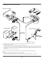
To connect SCART output (RGB)
Before connections: An exclusive SCART adapter (ADP-SC1)
and a commercially available SCART cable are required for
this connection.
NOTE: Audio signal is not available for this connection.
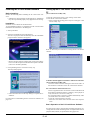
3. Turn on the power to the projector and your video equipment.
4. Use the RGB button on the remote control to select the
RGB input.
5. Press the MENU button on the remote control to display
the menu.
Video equipment
such as DVD player
Projector
6. From the Advanced menu, select [Projector Options] →
[Setup] → [Signal Select RGB] → [Scart].
SCART is a standard European audio-visual connector for TVs,
VCRs and DVD players. It is also referred to as Euro-connector.
ADP-SC1
Commercially available SCART cable
Female
1. Turn off the power to the projector and your video equipment.
NOTE: The ADP-SC1 SCART adapter is obtainable from your
NEC dealer in Europe.
Contact your NEC dealer in Europe for more information.
2. Use the NEC ADP-SC1 SCART adapter and a commercially available SCART cable to connect the RGB input of
your projector and a SCART output (RGB) of your video
equipment.
E–19
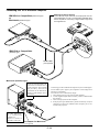
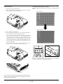
Connecting Your PC or Macintosh Computer
RGB signal cable (supplied)
To mini D-Sub 15-pin connector on the projector. It is recommended that you use a commercially available distribution amplifier if connecting a signal cable longer than
the supplied one.
IBM VGA or Compatibles (Notebook type)
or
Macintosh (Notebook type)
S
TU
R
TA
S WE
O
P
/ D
N N
O TA
S
Y
B
E
C
R
U
O
S
DIO
C
P
AU
ME
N
T
TO S
U
A DJU
A
S
S
E
C
C
A
U
D
R
A
C
S
NT
RO
T
IDE
O
CO
C
S-V
PC
LE
EN T ER
B
E
RG
CAN
L
VID
CEL
EO
US
B
PC
CA
RD
AC
IN
AU
DIO
RG
BI
NP
AU
DIO
UT
RG
B
S-V
IDE
O
PC
CO
NT
RO
IBM VGA or Compatibles
L
VID
EO
(Desktop type)
Audio cable
(not supplied)
Macintosh (Desktop type)
NOTE: The new Macintosh computer such as G3 will have the 15
pin HD connector. The LT150Z's
"Plug and Play" data will be
downloaded to the Macintosh.
Therefore, a Mac adapter will not
be necessary.
DIP
ON
1
For older Macintosh,
use a commercially
available pin
adapter to connect to
your Mac's video port.
2
3
4
5
Connecting your PC or Macintosh computer to your LT150Z projector will enable you to project your computer’s screen image for an
impressive presentation.
To connect to a PC or Macintosh, simply:
1. Turn off the power to your projector and computer.
2. Use the supplied signal cable to connect your PC or Macintosh to
the projector.
3. Turn on the projector and the computer.
4. If the projector goes blank after a period of inactivity, it may be
caused by a screen saver installed on the computer you’ve connected to the projector.
6
Pin adapter for Macintosh
(not supplied)
E–20
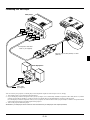
Connecting Your DVD Player
DVD player
S
TU
R
TA
S WE
O
P
/ D
N N
O TA
S
Y
B
S
O
U
R
C
E
AU
AU
DIO
ME
N
U
PC
EN T ER
Y
RG
B
S-V
IDE
O
CO
NT
RO
L
T
C
LE
E
S
Red
T
TO S
U
A DJU
A
S
S
E
C
C
A
D
R
A
C
DIO
L
White
C
P
R
CAN
CEL
VID
EO
Co
m
Y pon
Cb ent
Cr
US
B
PC
CA
RD
AC
IN
RG
BI
AU
Cb
Cr
NP
DIO
RG
UT
B
S-V
PC
CO
IDE
NT
O
RO
L
VID
EO
Component video cable
RCA3 (not supplied)
Optional 15-pin-to-RCA (female)3 cable
(ADP-CV1)
Audio Equipment
AU
R
DIO
L
Red
White
Audio cable
(not supplied)
You can connect your projector to a DVD player with component outputs or Video output. To do so, simply:
1. Turn off the power to your projector and DVD player.
2. If your DVD player has the component video (Y,Cb,Cr) output, use a commercially available component video cable (RCA3) and the
optional 15-pin-to-RCA (female)3 cable to connect your DVD player to the RGB INPUT connector on the projector.
For a DVD player without component video (Y,Cb,Cr) outputs, use common RCA cables (not provided) to connect a composite VIDEO
output of the DVD player to the Video Input of the projector.
3. Turn on the projector and DVD player.
NOTE: Refer to your DVD player’s owner’s manual for more information about your DVD player’s video output requirements,
E–21
Connecting Your VCR or Laser Disc Player
VCR/ Laser disc player
S
TA
P
E
W
O
S
TU
R
/ D
N N
O TA
S
B
Y
O
S
U
C
R
E
DIO
P
AU
C
A
A
U
D
N
R
ME
C
T
TO S
U
A DJU
A
S
S
E
C
C
S-V
PC
CO
IDE
NT
EN T ER
B
O
RO
T
C
LE
E
S
RG
CAN
L
VID
CEL
EO
US
B
PC
CA
RD
AC
IN
S-V
IDE
O
L
S-video cable
(not supplied)
R
AU
DIO
RG
VID
EO
B
S-V
IDE
White
PC
CO
NT
O
RO
L
VID
EO
Red
Audio equipment
Document camera
Audio cable
(not supplied)
VID
L
EO
R
White
Red
Video cable (not supplied)
Use common RCA cables (not provided) to connect your VCR, laser disc player or document camera to your projector.
To make these connections, simply:
1. Turn off the power to the projector and VCR, laser disc player or document camera.
2. Connect one end of your RCA cable to the video output connector on the back of your VCR or laser disc player, connect the other end to
the Video input on your projector. Use an audio cable (not supplied) to connect the audio from your VCR or laser disc player to your audio
equipment (if your VCR or laser disc player has this capability). Be careful to keep your right and left channel connections correct for
stereo sound.
3. Turn on the projector and the VCR or laser disc player.
NOTE: Refer to your VCR or laser disc player owner’s manual for more information about your equipment’s video output requirements.
NOTE:
• The LT150Z is not compatible with video decoded outputs of ISS-6020 and ISS-6010.
• An image may not be displayed correctly when a Video or S-Video source is played back in fast-forward or fast-rewind via a scan converter.
E–22
About Startup screen (Menu Language Select screen)
When you first turn on the projector, you will get the Startup screen.
This screen gives you the opportunity to select one of the seven menu
languages: English, German, French, Itilan, Spanish,Swedish and
Japanese.
To select a menu language, follow these steps:
1. Use the Select ▲ or ▼ button to select one of the seven languages for the menu.
2. Press the Enter button to execute the selection.
3. The Basic/Custom menu will be displayed in the language you
have selected.
To close the menu, press the Cancel button.
After this has been done, you can proceed to the advanced menu
operation.
If you want, you can select the menu language later. See “Language”
on page E-36.
E–23
3.OPERATION
Connecting the Power Cable and Turn on the Projector
Status of indicator light: turn on
Before you turn on your projector, ensure that the computer or video
source is turned on and that your lens cap is removed.
Normal mode:
stand by
STATUS
1
ON/STAND BY
POWER
Connect the supplied power cable to the projector.
EN
U
STATUS
STATUS
POWER
POWER
CA
S
E
LE
C
N C EL
T
M
steady orange light
S
O
U
R
C
E
P
C
C
A
R
D
A
A UT
D O
JU
A
C
S
C
T
E
S
S
E NTE R
O
S N/
TA
N
D
B
Y
AC
S
TA
TU
P
O
S
W
E
R
PC
CA
flashing green light
for one minute.
IN
Eco modo:
RD
steady green light
stand by
VID
S
RG
B
PC
A
E
-VID
CO
EO
US
B
STATUS
O
NTR
OL
ON/STAND BY
POWER
IO
UD
steady orange light
Plug the supplied power cable in the wall outlet. The projector will go into its standby mode and the power indicator will
glow orange.
STATUS
POWER
POWER
flashing green light steady green light
(Eco mode)
for one minute.
(Normal mode)
Turn on and off the Projector
Status of indicator light: turn off
ON
OFF
Power button
POWER
VIDEO
S-VIDEO
RGB1
AUTO ADJ.
ON
RGB2
LASER
ON/STAND BY
POWER
POWER ON/STAND BY button
press a minimum of
two seconds
MENU
steady green light
S
cooling down
S
R
E
W
O
P
TU
TA
SELECT
/ D
N N
O TA
S
R
N
CA
CE
POWER
E
C
R
U
O
S
TE
stand by
POWER
Y
B
EN
L
2
STATUS
Indicator
change to flashing
green light
3
Adjust a Projected Image
Select the Computer or Video Source
VIDEO
S-VIDEO
RGB1
RGB2
PC CARD
B
Y
S
O
U
R
C
E
P
C
A
R
T
TO S
U U
A J
D
A
S
S
E
C
C
A
D
C
B
S-V
IDE
O
P
ENTER
RG
E–24
steady orange light
D
To turn on the projector:
Only after you press the "ON/STAND BY" button on the projector cabinet or "POWER ON" button on the remote control
will the power indicator turn to green and the projector become ready to use.
NOTE: To turn the projector on by plugging in the power cable, use
the menu and enable the “Auto Start” feature. (See page E-39.)
NOTE: Immediately after turning on the projector, screen flicker may
occur. This is not a fault. Wait 3 to 5 minutes until the lamp lighting
is stabilized.
To turn off the projector:
First press the Power (ON/STAND BY) button on the projector cabinet or the POWER OFF button on the remote control
for a minimum of two seconds. The power indicator will glow
orange. After the projector turns off, the cooling fans keep
operating for 90 seconds.
NOTE: Do not disconnect the power cable during this time. Then,
unplug the power cable. The power indicator will go out.
Press the Source button on the remote control or the projector cabinet to select “Video” (VCR, document camera, or laser disc player),
S-Video”, “RGB” (computer or DVD with component output) or
“PC Card Viewer” (slides on a CompactFlash card) to display the
image.
Or press the “Menu” button on the remote control or the cabinet and
use the menu to select your video source: “Video”, “S-Video”, “RGB”
or “PC Card Viewer”.
NOTE: If no input signal is available, the projector will display a blue background (factory preset).
Adjusting the Image Size and the Focus
Use the Zoom ring to fine adjust the image size on the screen
Move the projector left to center the image horizontally on the
screen.
Use the Focus ring to obtain the best focus.
Rotate the rear foot to make the image square to the screen.
Place your projector on a flat level surface and Ensure that the
projector is square to the screen.
Use keystone correction for proper adjustment.
Lift the front edge of the projector to center the image vertically.
E–25
Adjust the Tilt Foot
1) Lift the front edge of the projector.
2) Press the Tilt button on the top of the projector to extend the
adjustable tilt foot (maximum height).
[Poor picture]
EN T ER
CAN
PC
SO
ON
ST
AT
/STA
UR
LE
CT
U
AU
AD TO
JU
ST
ME
CE
BY
US
PO
CEL
SE
S
N
CES
2
ND
CAR
D AC
1
Adjusting the Image Using Auto Adjust
The Auto Adjust function automatically optimizes the image in RGB
mode.
WER
1
[Normal picture]
3) Press and hold the Tilt button.
4) Lower the front of the projector to the desired height and release the button to lock the Adjustable tilt foot.
There is approximately 5 degrees of up and down adjustment
for the front of the projector. The rear foot height can be
changed, but the vertical distance from the bottom to the desk
or floor should be 0.14 ” (3.5mm) to make the projector horizontal on the flat surface. To fine-adjust the height of the rear
foot, remove the spacer (black rubber) and rotate the rear foot
to the desired height.
* If the projected image does not appear square to the screen
then use keystone correction for proper adjustment.
S
ON
OFF
O
U
R
C
E
U
S-VIDEO
RGB1
RGB2
P
PC
CEL
SE
LE
CT
N
EN T ER
CAN
VIDEO
CAR
AU
AD TO
D AC
JU
ST
CES
S
ME
4
POWER
C
A
LASER
S
E
LE
ENTER
SO
UR
CE
ON
MENU
R
AUTO ADJ.
T
TO S
U U
A DJ
A
S
S
E
C
C
A
D
C
/STA
ND
BY
3
PO
WER
ST
AT
US
CA
4
NCE
SELECT
Press the Auto Adjust button to adjust Position-H/V and Pixel Clock/
Phase for an optimal picture. Some signals may not be displayed
correctly or take time to switch between sources.
up
down
Do not use the tilt-foot for purposes other than originally intended.
Misuses such as gripping the tilt-foot or hanging on the wall can
cause damage to the projector.
E–26
Basic Operation
Volume control
Sound level from the speaker on the projector can be adjusted.
Selecting the computer or video source
D
VOLUME
Y
B
E
C
R
U
O
S
increase volume
Volume bar
C
P
T
TO S
U U
A J
D
A
S
S
E
C
C
A
D
R
A
C
RG
ENTER
B
S-V
IDE
O
P
Each time the Source button is pressed, the input source will change
as follows:
→ RGB → Video → S-Video → PC Card Viewer
decrease volume
If no input signal is present, the input will be skipped.
VIDEO
S-VIDEO
RGB1
Turning off picture and sound
RGB2
Press the Picture Mute button to turn off the image and sound for a
short period of time. Press again to restore the image and sound.
PIC-MUTE
PC CARD
Source display
Getting Help about how to operate the projector
You get the contents about Help.
HELP
Display Help
SELECT
Optimizing RGB image automatically
Press the Auto Adjust button to optimize an RGB image automatically.
E
C
R
U
C
P
U
N
T
TO S
U U
A J
D
A
S
S
E
C
C
A
D
R
A
C
ME
T
C
LE
E
S
ENTER
CA
NC
Press the Auto Adjust button to fine-tune the computer image or to
remove any vertical banding that might appear and to reduce video
noise, dot interference or cross talk (this is evident when part of your
image appears to be shimmering). This function adjusts the clock
frequencies that eliminate the horizontal banding in the image. This
function also adjusts the clock phase to reduce video noise, dot interference or cross talk. (This is evident when part of your image appears to be shimmering.)
This adjustment may be necessary when you connect your computer
for the first time.
NOTE: The Auto Adjust function does not work for component signal.
E–27
Exit Help
Using Pointer
4. Return the image to the original size.
You can use one of eight pointers to draw your audience's attention
to the portion of a projected image you want.
MAGNIFY
POINTER
Press the Pointer button to
display the pointer.
Correcting Keystone distortion
Press (+) or (-) to correct keystone (trapezoidal) distortion to make
the top or bottom of the screen longer or shorter so that the projected
image is rectangular.
SELECT
KEYSTONE
Use the Select button to move
the pointer.
Enlarging and Moving a Picture
You can enlarge the area you want up to 400 percent.
To do so:
1. Press the Pointer button to display the pointer.
Keystone distortion
Normal
POINTER
NOTE: The keystone angle can be corrected between 30 degrees upward and
30 degrees downward at a 0 degree-projection angle.
Depending on the type of graphics being used, the picture may get blurred or
keystone correction may not be possible when excessive keystone correction
is used.
The idea is, the closer you are to native resolution, the better image you will
see.
2. Move the pointer to the area you want to enlarge.
Freezing a picture
Press the Freeze button to freeze a picture. Press again to resume
motion.
SELECT
FREEZE
3. Enlarge the selected area.
When the Magnify (+) button is pressed, the pointer is changed
to a magnifying glass. To move the magnifying glass, use the
Select button.
MAGNIFY
E–28
Using the Menus
NOTE: The on-screen menu may not be displayed correctly while interlaced
motion video image is projected.
2. Use the Select buttons ▲ or ▼ to highlight your selection and
press the Enter button to place a check mark next to an option.
This action enables that feature.
Press the Enter button again to clear the check box.
1. Press the "Menu" button on the remote control or projector cabinet to display the Advanced Menu or Basic/Custom Menu.
NOTE: When using a USB mouse, click the mouse button to display the
menu. For other operations, do the same way as you use your PC mouse.
2. Press the ▲▼ buttons on the remote control or the projector cabinet to highlight the menu for the item you want to adjust or set.
3. Press the button or the "Enter" button on the remote control or
the projector cabinet to select a submenu or item.
4. Adjust the level or turn the selected item on or off by using "Select" or buttons on the remote control or the projector cabinet. The on-screen slide bar will show you the amount of increase or decrease.
5. Changes are stored until you adjust it again.
ENTER ......... Stores the setting or adjustments.
CANCEL ...... Return to the previous screen without storing settings or adjustments.
NOTE: You can close the main and sub menus simultaneously by pressing the PJ button on the remote control to cancel the Projector mode.
6. Repeat steps 2-5 to adjust an additional item, or press "Cancel"
on the projector cabinet or the remote control to quit the menu
display.
Customizing Basic/Custom Menu
The Basic/Custom menu can be customized to meet your requirements. Selecting a menu item from the “Basic/Custom Menu Edit”
list, allows you to custom tailor the menu items to your needs.
If you select an item with a solid triangle and press the Enter
button on the remote control or the projector cabinet, you can
enable all the items within that submenu.
Also you can turn on an item within the submenu without placing a check mark on the main menu item.
NOTE: Up to 12 main menu items (within Basic/Custom Menu Edit, not
including submenu items) can be selected.
3. In order for the changes to take effect, use the or button on
the remote control or the projector cabinet to highlight “OK”,
then press the Enter button. To cancel the changes, use the Select
▲ or ▼ buttons to highlight “Cancel” and press the “Enter” button. To return to the factory default, select “Reset” then press the
“Enter” button.
The default Basic/Custom Menu items are:
Source Select (RGB, Video, S-Video and PC Card Viewer), Picture, Volume,
Image Options (Keystone), Projector Options (Menu and Setup), Tools (Capture, PC Card Files and ChalkBoard) and Help (Contents and Information)
1. Select “Basic/Custom Menu Edit” to display the “Basic/Custom
Menu Edit” screen.
NOTE: Once you have selected OK on the Basic/Custom Menu Edit screen,
you cannot cancel the changes on the Menu screen. However, you can re-edit
the menu items over again as described in the steps above.
E–29
NOTE: If the “Advanced Menu” item has been selected on the Menu mode, you
get the “Confirmation Change Menu” upon completion of “Basic/Custom Menu”
editing. In this case, selecting “Yes” then “Enter” will close all the menus and
apply the changes from the Advanced menu to the Basic/Custom Menu.
If you select “No” then “Enter” functions, then all menu items will return to
the Advanced menu, but your changes will still be available within the “Basic/Custom Menu” selection. To display the previously tailored Basic/Custom Menu, select “Basic/Custom Menu” from the “Menu Mode”.
An item “To Advanced Menu” will be
added to the bottom of the Basic/Custom Menu.
Selecting this item and pressing the “Enter” button will display the “Advanced
Menu” features.
Using a USB Mouse
Using a USB mouse gives you a smooth operation. A commercially
available USB mouse is required.
NOTE:There may be some brands of USB mouse that the projector does not
support.
Operate the Menus using the USB mouse
Mouse Cursor
When connecting a USB mouse to the projector, you get a mouse
cursor on the screen.
Unless you use your USB mouse within 10 seconds, the mouse
cursor disappears.
Menu Display
Clicking with a mouse button displays the menu.
displays the pull-down menu.
Clicking
To close the menu, click anywhere in the background.
Adjusting and Setting Display
You can select a menu item and click with a mouse button to
make adjustments and setting.
Examples
Click (or press and hold) the mouse button or to adjust the
brightness.
Or click and drag the mouse button on the slide bar horizontally
to adjust it.
To save the adjustments, click
. The display is closed.
If you click anywhere in the background while displaying adjustment and setting menu or dialog box, you will get the main
menu at the clicking point.
E–30
Menu Tree
Advanced Menu
Source Select
Picture
Volume
Image Options
Color Management
Projector Options
Tools
Help
RGB
Video
S-Video
PC Card Viewer
Brightness/Contrast/Color/Hue/Sharpness
Volume
Keystone
Lamp Mode
Advanced Options
Factory Default
Normal/Eco
Aspect Ratio
Noise Reduction
Position/Clock
Resolution
Video Filter
Normal/Zoom/Wide Zoom/Cinema
Off/Low/Medium/High
Horizontal/Vertical/Clock/Phase
Auto/Native
On / Off
All Data/Current Signal
Gamma Correction
Color Matrix
White Balance
Menu
Setup
Normal/Natural 1/Natural 2
Select Color Matrix HDTV/SDTV
Select Color Matrix Type B-Y/R-Y,Cb/Cr,Pb/Pr
Brightness R/G/B, Contrast R/G/B
Page 1 Menu Mode(Advanced Menu, Basic/Custom Menu)
Basic/Custom Menu Edit
Language (English/German/French/Italian/Spanish/Swedish/Japanese)
Projector Pointer (Pointer 1-8)
Menu Display Time (Manual/Auto 5 sec/Auto 15 sec/Auto 45 sec)
Page 2 Message Source Display (On/Off)
No input (On/Off)
Direct Button Volume Bar (On/Off)
Keystone Bar (On/Off)
Capture
PC Card Files
ChalkBoard
Contents
Information
Page 1 Orientation (Desktop Front/Ceiling Rear/Desktop Rear/Ceiling Front)
Cinema Position (Top/Center/Bottom)
Background (Blue/Black/Logo)
Mouse Button(Right Hand/Left Hand)
Sensitivity(Fast/Medium/Slow)
Page 2 PC Card Viewer Options Show Folder List
(Auto Play/Manual Play)
Interval (5-300 sec)
Capture Options (High Quality/Normal/High Compression)
Page 3 Signal Select RGB (Auto/RGB/Component/Scart)
Video (Auto/NTSC3.58/NTSC4.43/PAL/PAL-M/PAL-N/PAL60/SECAM)
S-Video (Auto/NTSC3.58/NTSC4.43/PAL/PAL-M/PAL-N/PAL60/SECAM)
Page 4 Auto Adjust (RGB Only)
Auto Start
Power Management
Power Off Confirmation
Keystone Save
White Segment
Clear Lamp Hour Meter
Page 5 Communication Speed(4800/9600/19200/38400)
Default Source Select(Last/Auto/Select)
(RGB/Video/S-Video/PC Card Viewer)
Control Panel Key Lock (Enable/Disable)
Contents
Page1
Page2
Page3
Page4
Source Name/Input Terminal/Horizontal Frequency/Vertical Frequency/Sync Polarity
Signal Type/Video Type/Sync Type/Interlace/Resolution
Aspect Ratio/Gamma Correction/Noise Reduction/Color Matrix/Matrix Type
Remaining Lamp Time/Lamp Hour Meter/Projector Usage
E–31
Menu Elements
Tab
Title bar
Help Button
Close Button
Highlight
Radio button
Cancel Button
OK Button
Solid triangle
Check box
Grip icon
Tool bar
Slide bar
○ ○ ○ ○ ○ ○ ○ ○ ○ ○ ○ ○ ○ ○ ○ ○ ○ ○ ○ ○ ○ ○ ○ ○ ○ ○ ○ ○ ○ ○ ○ ○ ○ ○ ○ ○ ○ ○ ○ ○ ○ ○ ○ ○ ○ ○ ○ ○ ○ ○ ○ ○ ○ ○ ○ ○ ○
Menu windows or dialog boxes typically have the following elements:
Title bar:
Indicates the menu title.
Highlight:
Indicates the selected menu or item.
Solid triangle:
Indicates further choices are available. A highlighted triangle indicates the item is active.
Tab:
Indicates a group of features in a dialog box. Selecting on any tab brings its page to the front.
Radio button:
Use this round button to select an option in a dialog box.
Check box:
Place a checkmark in the square box to turn the option On.
Slide bar:
Indicates settings or the direction of adjustment.
OK button:
Press to confirm your setting. You will return to the previous menu.
Cancel button:
Press to cancel your setting. You will return to the previous menu.
Close button:
Click to close the window with saving changes. (USB mouse only)
Help button:
Indicates that help about that feature is available (USB mouse only). Press the Help button on the remote control to
display help.
Toolbar:
Contains several icons for specific tasks. It is also referred to as "launcher".
Grip icon:
Point the mouse here, and click and drag to move a toolbar.
E–32
Menu Descriptions & Functions
A press of the MENU button displays the toolbar; a press of the
MENU button again displays the Menu and hereafter each press of
the MENU button switches displaying between the Menu and the
toolbar.
Source Select
Enables you to select a video source such as a VCR, DVD player, laser
disc player, computer or document camera depending on what is connected to your inputs.
Press the "Select" button on the projector cabinet or ▲▼ buttons on
your remote control to highlight the menu for the item you want to adjust.
RGB
Selects the computer connected to your RGB or component signal.
NOTE: An optional component cable (Component V or ADP-CV1 cable) is
needed for a component signal.
Video
Selects what is connected to your Video input-VCR, laser disc player,
DVD player or document camera.
The launcher is a tool bar including the following buttons:
Drag .............. Drags to move the tool bar. (for USB mouse operation only)
Prev ............... Returns to the previous slide or folder.
Next ............... Advances to the next slide or folder.
Play ............... Plays back automatically or manually depending on the setting
on PC Card Viewer Options of the menu. This allows you to
move on to the next slide when "Manual Play" is selected.
Stop ............... Stops Auto Play while you are playing back and to resume playing from the selected slide or folder when "Auto Play" is selected.
Jump ............. Displays a list of slides while you are playing back.
Select ............ Displays a list of folders while you are playing back.
Setup ............. Displays the PC Card Viewer Options dialog box on Page 2 of
the Setup dialog box.
Delete ............ Deletes a captured slide(s) or all the captured slides in the selected folder.
View .............. Hides the tool bar while you are playing back. Clicking with the
right button of a mouse shows it again.
Provides access to controls for your image. Use the "Select" button
on the projector cabinet or the remote control to highlight the menu
for the item you want to adjust.
Picture (not available for PC Card Viewer)
S-Video
Selects what is connected to your S-Video input-VCR, DVD player,
or laser disc player.
NOTE: A frame may freeze for a brief period of time when a video is played
back in fast-forward or fast-rewind with a Video or S-Video source.
PC Card Viewer
This feature enables you to make presentations using a CompactFlash
card that contains captured images and slides created with the exclusive PC Card Viewer Utility contained in the CD-ROM. See page E43 for installing the PC Card Viewer Utility. The starting screen for
the PC Card Viewer varies depending on the settings of the Setup's
Page 2. See Setup on page E-38.
NOTE: Even if you switch the current PC Card Viewer source to another source,
the current slide is retained. When you return back to the PC Card Viewer,
you will get the slide that has been retained.
A launcher will appear when you press the MENU button.
Brightness ..... Adjusts the brightness level or the back raster intensity.
Contrast ......... Adjusts the intensity of the image according to the incoming
signal.
Color ............. Increases or decreases the color saturation level (not valid for
RGB).
Hue ................ Varies the color level from +/- green to +/-blue. The red level is
used as reference. This adjustment is only valid for Video and
Component inputs (not valid for RGB).
Sharpness ..... Controls the detail of the image for Video (Not valid for RGB
and Component).
Volume (not available for PC Card Viewer)
Adjusts the sound level of the projector.
NOTE: You can also display the volume bar without opening the menu. See
"Volume Bar (Direct Button)"on page E-37 for more details.
Prev
Play
Jump
Setup
View
Drag
Next
Stop
Select
Delete
E–33
Image Options
Aspect Ratio (not available for RGB and PC Card Viewer)
Aspect Ratio allows you to select the best Aspect mode to display
your source image.
When 4:3 is selected from the source (i.e. DVD player), the following selections will display:
Normal
Zoom
Wide Zoom
Cinema
Standard
4:3 Aspect
All 4 sides stretched
Left & Right
stretched
Left and right
stretched
Keystone
This feature corrects the keystone (trapezoidal) distortion to make
the top of the screen longer or shorter to be the same as the bottom.
Use the or buttons on the slide bar to correct the keystone
(trapezoidal) distortion.
Keystone distortion
When 16:9 is selected from the source (i.e. DVD player), the following selections will display:
Normal
Zoom
Wide Zoom
Cinema
16:9 image displayed All 4 sides stretched Left & right stretched stretched to display
Left and right
the true aspect
in 4:3 mode
Normal
NOTE: You can select three image positions for Cinema: Top, center, and
bottom.
See page E-37 for setting image positions.
NOTE: The keystone angle can be corrected between 30 degrees upward and
30 degrees downward at a 0 degree-projection angle.
Depending on the type of graphics being used, the picture may get
blurred or keystone correction may not be possible when excessive
keystone correction is used.
The idea is, the closer you are to native resolution, the better image
you will see.
Lamp Mode
This feature enables you to select two brightness mode of the lamp:
Normal and Eco modes. The lamp life can be extended up to 1500
hours by using the Eco mode.
Normal Mode ............... This is the default setting.
Eco Mode ..................... Select this mode to increase the lamp life.
NOTE: If you have selected the Eco mode, the lamp lights in Normal mode for
one minute after the projector is turned on. After one minute the lamp will
change to Eco mode.
E–34
Noise Reduction (not available for RGB and PC Card Viewer)
Resolution (when Auto Adjust is off)
You can select three levels video noise reduction.
NOTE: The lower the Noise Reduction level, the better the image quality by
way of higher video bandwidth.
This allows you to activate or deactivate the Advanced AccuBlend
feature.
Auto ............... Turns on the Advanced AccuBlend feature. The projector automatically reduces or enlarges the current image to fit the full
screen.
Native ............ Turns off the Advanced AccuBlend feature. The projector displays the current image in its true resolution.
See “Auto Adjust (RGB Only)” on page E-38 for turning on or
off the Auto Adjust feature.
NOTE: While you are displaying an image with higher resolution than the
projector's native resolution, even when you are in the Native mode, the image is displayed full screen using the Advanced AccuBlend feature.
Position/ Clock (when Auto Adjust is off)
Video Filter (when Auto Adjust is off)
This allows you to manually adjust the image horizontally and vertically, and adjust Clock and Phase.
This function reduces video noise.
Horizontal/Vertical Position:
Adjusts the image location horizontally and vertically using the
and buttons.
This adjustment is made automatically when the Auto Adjust is
turned on. See “Auto Adjust (RGB Only)” on page E-38 for turning on or off the Auto Adjust feature.
On ................. The low-pass filter is applied.
Off ................. The filter is removed.
Screen adjustments are possible even when the filter is On.
Factory Default
Clock ............. Use this item to fine tune the computer image or to remove any
vertical banding that might appear. This function adjusts the
clock frequencies that eliminate the horizontal banding in the
image.
Press the and buttons until the banding disappears.
This adjustment may be necessary when you connect your computer for the first time. This adjustment is made automatically
when the Auto Adjust is turned on.
Phase ............ Use this item to adjust the clock phase or to reduce video noise,
dot interference or cross talk. (This is evident when part of your
image appears to be shimmering.) Use the and buttons to
adjust the image.
Use "Phase" only after the "Clock" is complete.
This adjustment is made automatically when the Auto Adjust is
turned on.
Changes all adjustments and setting to the factory preset.
All Data .......... Reset all the adjustments and settings for all the signals to the
factory preset.
The items can be reset except Language, Communication Speed,
Remaining Lamp Time, Lamp Hour Meter and Projector Usage.
(To reset the lamp usage time, see “Clear Lamp Hour Meter” on
page E-39.)
Current Signal ..... Resets the adjustments for the current signal to the factory preset levels.
The items that can be reset for the currently projected image
are:
Picture (Brightness, Contrast, Color, Hue and Sharpness), Image Options (Aspect Ratio, Noise Reduction, Position/Clock,
Resolution and Video Filter) and Color Management (Gamma
Correction, Color Matrix and White Balance).
NOTE: The Volume, Keystone and all the items in the Projector Options can
be reset only when "All Data" is selected.
E–35
Color Management
Projector Options
Gamma Correction (not available for PC Card Viewer)
Use the or button to choose "Normal" when in a lighted room
and "Natural 1&2" when in a darkened room. "Natural 1" for better
flesh tone; "Natural 2" for true reproduction of middle tones.
Each mode is recommended for :
Normal .......... For the regular picture
Natural 1 ........ For true color reproduction of natural tones
Natural 2 ........ For dark portions of a picture
Menu
Color Matrix (available for component video signal only)
First select an appropriate color matrix to fit your component signal
for HDTV or SDTV. Then select an appropriate matrix type from BY/R-Y, Cb/Cr or Pb/Pr.
Allows you to set preferences for the on-screen menu.
Press “OK” to save your changes for all the features of Page 1 and
Page 2.
White Balance (not available for PC Card Viewer)
[Page1]
Menu Mode:
This feature allows you to select two menu modes: Advanced Menu
and Basic/Custom Menu.
Advanced Menu ............. This is the menu that contains all the available menus
and commands.
Basic/Custom Menu ...... This is the menu that you can customize using the
Basic/Custom Menu Edit to fit your needs.
The factory default Basic/Custom menu includes:
Source Select (RGB, Video, S-Video and PC Card Viewer), Picture, Volume,
Image Options (Keystone), Projector Options (Menu and Setup), Tools (Capture, PC Card Files and ChalkBoad) and Help (Contents and Information).
See page E-29 for instructions about how to customize the Basic/Custom Menu.
This allows you to adjust the white balance. Brightness for each color
(RGB)is used to adjust the black level of the screen;
Contrast for each color (RGB)to adjust the white level of the screen.
First use the ▲ or ▼ buttons to select R, G, or B for the brightness
and the contrast. Next use the or buttons to adjust the level.
Language:
You can choose one of seven languages for on-screen instructions.
The options are: English, German, French, Italian, Spanish, Swedish
and Japanese.
E–36
Projector Pointer:
This enables you to select from eight different Pointer icons for the
"Pointer" button on your remote control.
After moving your Pointer icon to the area you want on the screen,
press the Magnify button on the remote control to enlarge the selected area on the screen. See page E-28 for more details.
NOTE: There may be cases where the Pointer function is not available (ex. a
non-interlace signal at 15kHz such as video game.)
Menu Display Time :
This option allows you to select how long the projector waits after
the last touch of a button to turn off the menu.
The preset choices are "Manual", "Auto 5 sec", "Auto 15 sec", and
"Auto 45 sec". The "Auto 45 sec" is the factory preset.
Manual .......... The menu can be turned off manually.
Auto 5 sec ..... The menu will automatically be turned off in 5 seconds if no
buttons are pressed within 5 seconds.
Auto 15 sec ..... The menu will automatically be turned off in 15 seconds if no
buttons are pressed within 15 seconds.
Auto 45 sec ..... The menu will automatically be turned off in 45 seconds if no
buttons are pressed within 45 seconds.
Direct Button:
Volume Bar:
This option turns on or off the volume bar when you adjust the sound
volume using VOL+/–(up and down) button.
On ................. You can increase or decrease the sound volume with the volume bar on screen.
Off ................. You can increase or decrease the sound volume without having
to use the volume bar.
Keystone Bar:
This option turns on or off the keystone bar when you adjust the
keystone using KEYSTONE +/– button on the remote control.
On ................. You can increase or decrease the level with the keystone bar on
screen.
Off ................. You can increase or decrease the level without having to use the
keystone bar.
Setup
Enables you to set operating options.
Press "OK" to save your changes for all the features of Page1, Page2,
Page3, Page 4 and Page 5.
[Page1]
[Page2]
Orientation:
This reorients your image for your type of projection.
The options are: desktop front projection, ceiling rear projection,
desktop rear projection, and ceiling front projection.
Message:
You can choose the desired information to be displayed on the screen.
On ................. The message will be displayed.
Off ................. The message will not be displayed.
Source Display: You can turn on and off the information for input
name such as VIDEO and RGB.
When this option is on, the current input will be displayed each time
you switch sources or turn on the projector.
No Input: This option turns on or off the "No Input" message to be
displayed in the top right corner on the screen.
Cinema Position:
This feature selects the vertical position of the image when viewing
video with Cinema aspect ratio selected.
When Cinema aspect ratio is selected on earlier models, the image is
displayed with black borders on the top and bottom.
You can select the vertical position among three options:
Top ................ Image position is at the top with a black border on bottom.
Center ............ Image position is at the center with black borders on top and
bottom.
Bottom ........... Image position is at the bottom with a black border on top.
Background:
Use this feature to display a blue/ black screen or logo when no signal is available. The default background is blue. You can change the
logo screen using the PC Card Files feature. See page E-40.
E–37
Mouse Settings:
This option lets you to change your USB mouse settings. The mouse
settings feature is available for USB mouse only. Choose the settings you want:
Mouse Button ................ "Right Hand" or "Left Hand"
Mouse Sensitivity .......... "Fast", "Medium" or "Slow"
[Page3]
Signal Select
[Page2]
PC Card Viewer Options
RGB:
Allows you to choose "RGB" for an RGB source such as a computer, or "Component" for a component video source such as a
DVD player. Normally select "Auto" and the projector automatically
detects a component signal. However there may be some component
signals that the projector is unable to detect. If this is the case, select
"Component". Select “Scart ” for the European Scart.
Show Folder List:
If this option is checked, when PC Card Viewer input is selected on
the projector, the folder lists will be displayed and allows you to
select the presentation from a CompactFlash card.
Auto Play:
If this option is checked, any given slide will start to play automatically.
VIDEO and S-VIDEO:
This feature enables you to select composite video standards manually. Normally select "Auto".
Select the video standard from the pull-down menu.
This must be done for Video and S-Video separately.
[Page4]
Auto Play Interval:
You can specify interval time between 5 and 300 seconds.
NOTE: The Auto Play Interval time set on the PC Card Viewer Utility overrides
the one set here.
Manual Play:
Views a slide manually when PC Card Viewer input is selected.
NOTE: The Auto Play and Manual Play options determine the behavior of the
/
] icon on the Viewer toolbar.
Play/Stop [
NOTE: If you check "Auto Play" and select "PC Card Viewer" on the projector,
the slides will automatically start to play back from any given slide.
Capture Options: (available for JPEG only)
These options are used for the Capture function that you can select
from Tools. You have three options for JPEG compression quality:
High quality, Normal and High Compression.
High Quality .......................... Gives quality of JPEG a priority.
Normal .................................. Gives normal JPEG quality.
High Compression ................ Gives compression a priority.
Auto Adjust (RGB Only):
When "Auto Adjust" is set to "On", the projector automatically determines the best resolution for the current RGB input signal to project
an image using NEC's Advanced AccuBlend Intelligent Pixel Blending Technology.
The image can be automatically adjusted for position and stability;
"Horizontal Position", "Vertical Position", "Clock", "Phase", and
"Resolution."
On ................. Automatically adjusts image "Horizontal Position", "Vertical Position", "Clock", "Phase" and "Resolution".
Off ................. User can adjust the image display functions ("Horizontal Position", "Vertical Position", "Clock", "Phase" and "Resolution")
manually.
E–38
Auto Start:
Turns the projector on automatically when the power cable is inserted into an active power outlet. This eliminates the need to always
use the "Power" button on the remote control or projector cabinet.
[Page5]
Power Management:
When this option is on and there is no RGB input for five minutes or
more, the projector will automatically turn itself off.
Power Off Confirmation:
This option determines whether a confirmation dialog for turning
off the projector will appear or not.
NOTE:
When the confirmation message is displayed, you must be in the Projector
mode to operate your projector using the remote control. If not, press the PJ
button on the remote control to change your projector to the Projector mode.
The button lights to indicate that you are in the Projector mode.
Keystone Save:
This option enables you to save your current keystone settings.
Saving your change once affects all sources. The changes are saved
when you turn off the projector.
White Segment:
You can put emphasis on either brightness or color for a projected
image.
If you prefer putting emphasis on brightness, place a checkmark in
the box to turn the option on. If you prefer an image in truer color,
turn off this option.
Clear Lamp Hour Meter:
Resets the lamp clock back to zero. Pressing this button appears a
confirmation dialog box. To reset the lamp usage hour, press "OK".
NOTE: The projector will turn off and go into standby mode after 1100 hours
(up to 1600 hours in Eco mode) of service. If this happens, press the "Help"
button on the remote control for ten seconds to reset the lamp clock back to
zero. Do this only after replacing the lamp.
Communication Speed:
This feature sets the baud rate of the PC Control port (Mini DIN 8
Pin).
It supports data rates from 4800 to 38400 bps.
The default is 38400 bps. Select the appropriate baud rate for your
equipment to be connected.
Default Source Select:
You can set the projector to default to any one of its inputs each time
the projector is turned on.
Last ............... Sets the projector to default to the previous or last active input
each time the projector is turned on.
Auto ............... Searches for an active source in order of RGB → Video → SVideo → PC Card Viewer → RGB and displays the first found
source.
Select ............ Displays the selected source input every time the projector is
started up. Select an input from the pull-down menu.
Control Panel Key Lock:
This option turns on or off the Control Panel Key Lock function.
NOTE:
* This Control Panel Key Lock does not affect the remote control and the PC
Control functions.
* When the cabinet buttons are disabled, pressing and holding the CANCEL
button for about 10 seconds will change the setting to enabled.
E–39
PC Card Files:
Displays a list of all the files stored in the CompactFlash card so that
you can select a file you want to display. You can also sort files by
file name or date, or display the file.
Although a list of all the files in the CompactFlash card is displayed,
you can view files in idx, text, HTML, JPEG and BMP format only.
Selecting BMP and JPEG files automatically switches to the PC Card
Viewer source.
Tools
NOTE: When an image with a resolution of XGA(1024768) or higher is
projected, the PC Card Files screen may not be correctly displayed.
Provides tools for capturing images, displaying files in a
CompactFlash Card and drawing.
NOTE: The "Capture" and "PC Card Files" features are required for a
CompactFlash card.
Capture:
Allows you to capture an image from a source that is currently being
displayed. The image is saved as JPEG in the CompactFlash card.
When you select Capture from the menu, you will get a tool bar. You
can capture an image directly using the tool bar when the menu is
not displayed.
Capture
Exit
Selecting "Execute" displays the file you selected.
When you select a JPEG or BMP file and press the Enter button on
the remote or the cabinet, or “Execute” on the above, you will get a
toolbar. This toolbar is used to return to the PC Card Files screen.
Drag
Return
Freeze
Drag
The tool bar includes the following buttons:
Drag .............. Drags to move the tool bar. (for USB mouse operation only)
Capture .......... Captures an image and save it as a JPEG file in a CompactFlash
card.
Freeze ............ Freezes and unfreezes images.
Exit ................ Exits the Capture function.
Unless a CompactFlash card is inserted into the PC Card slot of the
projector, the Capture feature is not available.
The "Card Error" display means that the free space of the
CompactFlash card is insufficient for saving images. Make more
space available on the card by erasing unwanted images with your
PC. The number of images that can be captured depends on the size
of the CompactFlash card.
Close
Drag .............. Drags to move the tool bar. (for USB mouse operation only)
Return ............ Returns to the PC Card Files screen.
Close ............. Close the toolbar.
Changing Background Logo
The Logo button allows you to select a background logo from graphic files
on a CompactFlash card and change to it as the background logo.
NOTE: File size must be 64KB or less. Other file formats than JPEG and BMP
are not available.
1. Use the Select ▲ or ▼ button to select a JPEG or BMP file for
your background logo.
NOTE: Be sure not to turn off the power or remove the CompactFlash card
while capturing an image. Doing so could cause a loss of the data in the
CompactFlash card or damage to the card itself.
NOTE: Captured images with higher resolution than the projector's native
resolution cannot be displayed correctly.
E–40
2. Use the Select and then ▼ button to select “Logo”.
3. Press the Enter on the remote control or the cabinet. You will get
the confirmation dialog box.
Contents:
4. Select “OK” and press the Enter button. This completes changing a logo for the background.
* Once you have changed the background from the NEC logo to
another, you cannot return the logo to background even by using
Factory Default. To do so, repeat the above steps. The NEC logo
file is included on the supplied CD-ROM (/logo/nec_b_x.jpg).
ChalkBoard: (available only when using with USB mouse)
Provides the tool bar for producing freehand drawings.
Pen
Eraser
Provides an online help about how to use the menus. An underlined
link means that you can move to an adjustment item directly.
Selecting the underlined link and pressing ENTER moves to the corresponding adjustment item.
View
Drag
Exit
Color
Information:
Clear
Drag .............. Drags to move the tool bar. (for USB mouse operation only)
Pen ................ Left-click and drag to draw. Left-click [ ▲ ] or right-click the
pen icon to display the pen palette containing four lines of different thickness from which you can select a line you prefer by
left-clicking.
Color ............. Selects a color. Left-click to display the color palette from which
you can select a color you prefer by left-clicking.
Eraser ............ Left-click and drag to erase part of a drawing. Left-click [▲ ] or
right-click the eraser icon to display the eraser palette containing four eraser of different thickness from which you can select
an eraser you prefer by left-clicking.
Clear .............. Left-click to clear the drawing completely from the ChalkBoard
screen.
View .............. Hides the tool bar by left-clicking. Right-clicking anywhere on
the screen displays the ChalkBoard tool bar again.
Exit ................ Clears the complete drawing and exits the ChalkBoard.
NOTE:
* The ChalkBoard feature is available only when a USB mouse is used. Freehand drawings cannot be saved or captured.
* The menu is not available while you display the ChalkBoard screen.
* The Capture and the Source Display function are not available on
ChalkBoard screen.
* Switching slides clears a drawing completely.
Help
Displays the status of the current signal, and the lamp and the projector usage hours.
This dialog box has four pages.
The information included are as follows:
[Page 1]
Source Name
Input Terminal
Horizontal Frequency
Vertical Frequency
Sync Polarity
[Page 2]
Signal Type
Video Type
Sync Type
Interlace
Resolution
[Page 3]
Aspect Ratio
Gamma Correction
Noise Reduction
Color Matrix
Matrix Type
[Page 4]
Remaining Lamp Time (%)
Lamp Hour Meter (H)
Projector Usage (H)
NOTE:The progress indicator shows the percentage of remaining bulb life.
The value informs you of the amount of lamp and projector usage respectively.
Remaining Lamp Time Display:
When the remaining lamp time reaches 0, the Remaining Lamp Time
bar indicator changes from 0% to 100 Hours and starts counting down.
If the remaining lamp time reaches 0 hours, the projector will not
turn on regardless of whether the lamp mode is set to Normal or Eco.
E–41
Using the PC Card Viewer function
Inserting the CompactFlash Card
NOTE: When using the supplied software (CD-ROM)
The software is designed to use with a personal computer only. Do not play
the software on CD player. Doing so could cause damage to speakers.
• Hold the CompactFlash card horizontally and insert it slowly
into card slot with its top facing up.
• The eject button pops out once the CompactFlash card is fully
inserted.
Check that the CompactFlash card is fully inserted.
NOTE: Do not try to force the CompactFlash card into the slot.
Features
The Viewer feature allows slides stored on a CompactFlash memory
card (referred to as CompactFlash card in this manual) to be displayed on the projector. Even if no computer is available, presentations can be conducted simply with the projector. This feature is
convenient for holding presentations at meetings and in offices, as
well as for playing images taken on digital cameras.
PC
EO
CO
NT
RO
CA
L
VID
NCEL
EO
US
PC
B
CA
RD
AC
IN
Easy to use
• Presentations can be started immediately simply by inserting a
CompactFlash card (not supplied)
• Easy slide switching
• Remote control operation
• Jumping to list of slides or any specific slide
Ejecting the CompactFlash Card
High quality images
Press the eject button. The CompactFlash card pops out a little. Grasp
the edges of the CompactFlash card and pull it out. Do not eject the
CompactFlash card while its data is being accessed.
• High resolution up to 1024768 dots
• 24-bit full color playback
• Viewing of digital camera images
Eject button
Simple utility software (for computer)
• PC Card Viewer Utility operable on Windows 95/98 / Me /NT4.0
(SP3 or later)/2000
• Slides can be created by capturing the currently displayed image
• Control screen for displaying lists of slides and editing
• PC Card Viewer PPT Converter 1.0 [Add-In Version] converts
files created with Microsoft PowerPoint 95/97/2000 (hereafter
referred to as PowerPoint) into indexes playable with PC Card
Viewer
* Microsoft, Windows and PowerPoint are registered trademarks
of Microsoft Corporation.
Inserting and Ejecting a CompactFlash Card
RO
L
VID
EO
US
B
PC
CA
RD
AC
IN
Install the CompactFlash card on a PC card adapter when using on
your PC.
• Set the CompactFlash card in the direction shown in the diagram and insert it into the card adapter.
A CompactFlash card is used to view presentation data prepared on
the computer and to capture and play images projected with the projector.
P
A Cd Ca
ap r
te d
r
Card adapter (not supplied)
8M
B
CompactFlash card
(not supplied)
Direction for Inserting the CompactFlash Card
The CompactFlash card has a top and bottom and must be inserted into the PC card slot in a specific direction. It cannot be
inserted backwards or upside-down. Attempting to force it into
the slot in the wrong direction may break the internal pin and
damage the card slot. Refer to the CompactFlash card's operating instructions for the proper direction of insertion.
CompactFlash Card Type
The PC Card slot accepts CompactFlash only.
E–42
Installing the PC Card Viewer Software
Starting Up the PC Card Viewer Software on your
PC
Before Installing
Perform the following before installing the PC Card Viewer software:
• If Windows is already started, exit all applications. Installation
may not be performed properly if any applications are running.
Installation
(PC Card Viewer Utility 1.0)
Use the PC Card Viewer Utility 1.0 for creating viewer slides.
To start the PC Card Viewer software:
* Select [Start]-[Programs]-[NEC Projector Tools]-[PC Card
Viewer Utility 1.0].
Install the viewer software as described below.
To quit installation before it is completed, press the "Cancel" button
then follow the instructions in the dialog box.
1. Start up Windows.
2. Insert the CD-ROM into the CD-ROM drive.
The auto CD play function automatically starts the CD-ROM's
program and the contents screen appears.
Refer to online help for instructions on using the PC Card Viewer
software.
* The auto CD play function operates if the "Auto insert notification" box in the computer's CD-ROM control panel is checked.
(The box is checked by default.)
3. Click [Installing the PC Card Viewer Utility 1.0]
The setup dialog appears.
Contents of the English version PC Card Viewer software
(PC Card Viewer Utility 1.0)
This is the software used for creating PC Card Viewer slides. In
this manual it is referred to as the "PC Card Viewer software".
PC Card Viewer PPT Converter 1.0
This is an application that converts files created with Microsoft
PowerPoint 97/2000 into indexes so that they can be played directly with the PC Card Viewer Utility 1.0.
PC Card Viewer PPT Converter is installed automatically when
you install the PC Card Viewer Utility.
To start PC Card Viewer PPT Converter:
* Select PC Card Viewer PPT Converter from NEC Projector
Tools.
* Follow the instructions in the setup dialog to complete the installation.
For instructions on uninstalling the PC Card Viewer software, see
page E-47.
Basic Operation of the PC Card Viewer Software
PC Card Viewer Utility is an application for editing documents, converting them into slides and storing them on CompactFlash cards as
playback data (indexes) for presentations using projectors.
E–43
Operating the PC Card Viewer Function from
the Projector (playback)
This section describes the operation for showing slides of presentation documents created using the PC Card Viewer function with the
projector.
It is also possible to make slides directly from the images projected
with the projector.
Drag:
Drags to move the tool bar. This is available for
USB mouse operation only.
Prev:
Returns to the previous slide or folder. Or this lets
you play slides back in reverse.
Next:
Advances to the next slide or folder. Or this lets
you play slides back.
Play:
Plays back automatically or manually depending
on the setting on PC Card Viewer Options of the
menu. This allows you to move on to the next slide
when “Manual Play” is selected.
Stop:
This allows you to stop Auto Play while you are
playing back and to resume playing from the selected slide or folder when “Auto Play” is selected.
Jump:
Displays a list of slides while you are playing back.
Select:
Displays a list of folders while you are playing
back.
Setup:
Displays the PC Card Viewer Options dialog box
on Page 2 of the Setup dialog box.
Delete:
Deletes a captured slide(s) or all the captured slides
in the Capture – specific folder.
View:
Hides the tool bar while you are playing back.
Pressing the MENU button or clicking with the
right button of a mouse shows it again.
Projecting slides
1. Insert a CompactFlash card into the card slot.
Insert the CompactFlash card with the side with the insertion direction arrow on the top.
* Press the eject button to eject the card.
2. Select the “PC Card Viewer” from the Source Select menu.
3. Project slides.
Checking “Show Folder List”, means that selecting PC Card
NOTE: If no memory card is inserted in the PC CARD slot, there is no signal,
and a black, blue or logo background is displayed, depending on the setting.
Viewer input displays a list of the folders in the CompactFlash
card and if “Auto Play” is checked the projector automatically
starts to play slides at the first slide of the folder you have
selected.
A tool bar will appear when you press the MENU button on the remote control or the projector cabinet or clicking with the right button of a mouse.
Prev
Play
Jump
Setup
View
Playback is stopped when SLIDE +/- button on the remote control or
button on the cabinet is pressed in Auto Play mode.
NOTE: Up to 12 indexes can be displayed on the list of folders. The folder in
the right bottom is always a folder exclusively for captured images, but is
only displayed when images have been captured. To display the list of folders
when there are 13 or more indexes stored on the CompactFlash card, select
"Edit index" from the PC Card Viewer software's "File" menu and move the
index you want to display to within 12 indexes from the top of the folder
index. For details on indexes, refer to the PC Card Viewer software's help
folder.
Drag
Next
Stop
Select
Delete
The tool bar includes the following buttons:
E–44
When the tool bar is not displayed:
Auto Play Mode
Press the FOLDER LIST button on the remote control to display
folders from a CompactFlash card in the projector’s PC Card slot.
• If the “Auto Play” option is selected in “PC Card Viewer Options” of the menu, any given slide will start to play automatically. You can also specify Auto Play Interval between 5 and
300 seconds.
Multi cursor (blue marks)
Folder
SLIDE
Folder
Folder
Folder
Switching to Slides Directly from Other Input Modes
With this function it is possible to switch directly to a slide when the
picture of a VCR or computer is being projected.
Folder
Example:
Current folder number
02 : 0001 / 0008
Number of all slides
in folder
Current slide number
Use the SLIDE +/- button to
advance to the next folder or
return to the previous folder.
When conducting presentations using a combination of slides and
moving pictures from a VCR, etc., it is possible to switch from a PC
Card Viewer slide to the video picture then back to the PC Card
Viewer slide simply by using a source button and PC CARD button.
NOTE: Even if you switch the current PC Card Viewer source to another source, the current slide is retained. When you return back to
the PC Card Viewer, you will get the slide that has been retained.
Folder
ON
OFF
POWER
VIDEO
S-VIDEO
RGB1
RGB2
LASER
AUTO ADJ.
Slide(Table) cursor
(green marks)
MENU
Slide
Slide
Slide
Slide
Slide
Slide
Slide
Slide
EN
02 : 0004 / 0008
L
SELECT
TE
R
CA
NC
E
PJ
Use the SLIDE +/- button to
advance to the next slide or return to the previous slide.
Slide
FOCUS
HELP
ZOOM
POINTER PC CARD
KEYSTONE MAGNIFY
NOTE: You can also use the and button on the remote control to select
folders or slides.
If you use the and button on the remote control for PC Card Viewer
operation, press the PJ button to switch to the Projector mode and the PJ
button lights red.
FREEZE
PIC-MUTE
SHIFT
VOLUME
SLIDE
FOLDER
SLIDE
LIST
SELECT
L
EN
Works as the Select button on
the projector.
TE
R
CA
NC
E
NOTE: The PC card editing operation cannot be performed from the
projector. Do so using the PC Card Viewer software.
PJ
Lit red
FOCUS
ZOOM
SHIFT
E–45
Capturing Images Displayed on the Projector
Storing images displayed on the projector on the
CompactFlash card
Preparations:
Insert the CompactFlash card into the card slot.
Insert the CompactFlash card with the side with the insertion
direction arrow on the top.
* Press the eject button to eject the card.
1. Project the image you wish to store on the projector.
2. Select the “Capture” from the Tools menu.
NOTE:
• File size of the captured image varies depending on the resolution of an
input signal.
• Since an image data is compressed with the JPEG format, the image is
slightly degraded.
NOTE: An hourglass indicating that an image is being captured appears on
the projector's display. Do not eject the CompactFlash card or turn off the
projector's power while this icon is displayed. Doing so will damage the
CompactFlash card data.
If the CompactFlash card data is damaged, use a computer to repair the data.
NOTE: The folder in the right bottom is always a folder exclusively for captured images. To display the list of folders when there are 13 or more indexes
stored on the CompactFlash card, select "Edit index" from the PC Card Viewer
software's "File" menu and move the index you want to display to within 12
indexes from the top of the folder index. For details on indexes, refer to the
PC Card Viewer software's help file.
Freeze
Drag
Capture Exit
3. A tool bar will appear.
The tool bar includes the following buttons:
Drag:
Drags to move the tool bar (for USB mouse operation only).
Capture: Captures an image and save it as a JPEG file in a
CompactFlash card.
Freeze: Freezes and unfreezes images.
Exit:
Exits the Capture function. Another option to exit
the Capture function is to press MENU or CANCEL
button on the remote control or projector cabinet.
NOTE: You can compress a captured file (JPEG) using the Capture Options in
the Setup dialog. See page E-38.
NOTE: Captured images with higher resolution than the projector's native
resolution cannot be displayed correctly.
E–46
Uninstalling the PC Card Viewer Software
Deleting Captured Images
Prev
Play
Jump
Setup
View
Even if you do now know the PC Card Viewer software's file names
or where they are stored, the PC Card Viewer software files can be
easily removed from the system using the "Install/Uninstall Applications" control panel in Windows. (Normally there is no need to
perform this operation.)
Drag
Next
Stop
Select
Delete
Uninstalling the software
Using the Delete button on the tool bar for PC Card Viewer can delete captured images.
To delete captured images:
1) Select PC Card Viewer.
2) Use button to select the Capture folder in the right bottom of
the screen.
3) Press the MENU button to display the tool bar.
4) Use the or button to select the Delete icon and press the
ENTER button or click with a mouse button.
Use the procedure described below to uninstall the PC Card Viewer
software files.
1. From the "Start" menu, select "Settings" then "Control Panels".
Viewing Digital Images
Digital images can be played with the PC Card Viewer if the following conditions are met:
• If the image can be stored on an MS-DOS format CompactFlash
card
• If the image can be stored in a format supported by the PC Card
Viewer.
With the PC Card Viewer, images on the card are searched for
in directories and images in JPEG or BMP format are recognized as slides.
Searchable directories are directories within two steps from the
root directory, and searchable images are images within the first
12 files in the directory. Only file and slide switching are possible.
NOTE: The maximum number of images recognized as slides within one directory is 128.
2. In the "Control Panels" dialog box, double-click on "Add/Remove Programs".
3. In the "Add/Remove Programs Properties" dialog box, click the
"Setup/Remove" tab, then select "PC Card Viewer Utility 1.0"
from the list of applications and click on "Add/Remove".
4. In the "Confirm File Deletion" dialog box, click "Yes".
5. Once the application is uninstalled, click on "OK" in the "Remove Program From Your Computer" dialog box.
E–47
Terminology
PC card
This is the name of a card currently being standardized by the Japan Electronic Industry Association (JEIDA) and
PCMCIA (Personal Computer Memory Card Interface Association) of the United States.
ATA card
A type of PC card. ATA was originally a type of interface between computers and fixed disk devices. The ATA
card is a standard card-type recording medium.
CompactFlash
CompactFlash card is a small removable card conforming to ATA specifications. It is one-fourth the volume of a
PCMCIA card.
TYPE (I, II and III)
PCMCIA 2.1 PC cards are divided into three types according to their thickness: Type I (3.3 mm), Type II (5.0 mm)
and Type III (10.5 mm).
BMP
A type of image format. The standard Windows Bit Map format used for MS-DOS/Windows-compatible computers.
JPEG
A type of image format. "JPEG" is the abbreviation of Joint Photographic Experts Group. JPEG compression
offers efficient data storage. The data not required for displaying the image is identified and deleted. Since the
data is deleted, JPEG algorithms are said to be irreversible. This means that once the image is compressed, the
decompressed image it is not the same as the original image.
E–48
4. MAINTENANCE
This section describes the simple maintenance procedures you should
follow to replace the lamp.
3 Remove the lamp housing by pulling out the handle.
NOTE: There is an interlock on this case to prevent the risk of electrical
shock. Do not attempt to circumvent this interlock.
Replacing the Lamp
After your lamp has been operating for 1000 hours (up to 1500 hours
: Eco mode) or longer, the “Status” indicator in the cabinet will go
on and the message will appear. Even though the lamp may still be
working, replace it at 1000 hours (up to 1500 hours : Eco mode) to
maintain optimal projector performance.
DIO
PC
CO
NT
RG
RO
Interlock
AU
CAUTION
• DO NOT TOUCH THE LAMP immediately after it has been
used. It will be extremely hot. Turn the projector off, wait 90
seconds, and then disconnect the power cable. Allow at least
one hour for the lamp to cool before handling.
• DO NOT REMOVE ANY SCREWS except the lamp cover
screw and three lamp case screws. You could receive an electric shock.
• The projector will turn off and go into stand by mode after 1100
hours (up to 1600 hours : Eco mode) of service. If this happens,
be sure to replace the lamp. If you continue to use the lamp after
1000 hours (up to 1500 hours : Eco mode) of use, the lamp bulb
may shatter, and pieces of glass may be scattered in the lamp
case. Do not touch them as the pieces of glass may cause injury.
If this happens, contact your NEC dealer for lamp replacement.
L
4 Insert a new lamp housing until the lamp housing is plugged into
the socket.
CAUTION: Do not use a lamp other than the NEC replacement lamp
(LT51LP).
AU
DIO
PC
RG
CO
NT
RO
B
L
5 Secure it in place with the three screws.
Be sure to tighten the screws.
1 Loosen the lamp cover screw until the screwdriver goes into a
freewheeling condition and remove the lamp cover. The lamp
cover screw is not removable.
AU
To replace the lamp:
DIO
PC
CO
NT
RG
RO
L
B
S-VI
O
DE
AU
6 Reattach the lamp cover.
DIO
PC
RG
CO
NT
RO
B
S-VI
DE
L
O
VIDE
US
O
B
PC
CA
RD
AC
AU
IN
DIO
PC
RG
CO
NT
RO
B
S-VI
DE
L
O
2 Loosen the three screws securing the lamp housing until the screwdriver goes into a freewheeling condition. The three screws are
not removable.
7 Tighten the lamp cover screw.
Be sure to tighten the screw.
AU
DIO
PC
CO
NT
RO
RG
DIO
AU
L
B
PC
B
RG
S-VI
DE
L
RO
NT
CO
O
8 After you install a new lamp, select the Main menu → [Projector
Options] → [Setup] → [Page 4] → [Clear Lamp Hour Meter] to
reset the lamp usage hours.
If the projector will not be turned on after using 1100 hours (up
to 1600 hours : Eco mode) of service, press and hold the [Help]
button on the remote control for ten seconds or longer to reset the
lamp time clock to zero.
E–49
VIDE
O
US
B
PC
CA
RD
AC
IN
5. TROUBLESHOOTING
This section helps you resolve problems you may encounter while setting up or using the projector.
Power/Status Light Messages
Condition
Power Indicator
Status Indicator
Standby
Steady orange
–
–
Cooling down
Blinking green
–
Blinks green for 90 seconds
Lamp in Normal mode
Steady green
–
–
Lamp in Eco mode
Steady green
Steady green
–
Retrying to turn on lamp
Steady green
Blinking orange
The projector retries 3 times at an interval of
15 sec for max. 45 sec)
One minute after lamp is turned
on
Blinking green
No light in Normal mode / Steady
green in Eco mode
–
Lamp has reached its end of life
(Normal: 1000 hours or over)
(Eco: 1500 hours or over)
Steady green
Steady red
Message appears on screen during 1000-1100
hours (1500-1600 hours: Eco mode) of lamp
usage. The projector reaches its end of life.
Please replace the lamp as soon as possible
Lamp life has reached its end of
life
(Normal: 1100 hours or over)
(Eco: 1600 hours or over)
Steady orange
Steady red
The projector is in standby mode and cannot
be turned on.
Lamp cover error
Steady orange
Blinking red (1 sec interval)
The projector is in standby mode and cannot
be turned on.
Temperature error
Steady orange
Blinking red (4 sec interval)
The projector is in standby mode and cannot
be turned on.
Fan error
Steady orange
Blinking red (8 sec interval)
The projector is in standby mode and cannot
be turned on.
Lamp error
Steady orange
Blinking red (12 sec interval)
The projector is in standby mode and cannot
be turned on.
E–50
Note
Common Problems & Solutions
Problem
Check These Items
Does not turn on
• Check that the power cable is plugged in and that the power button on the projector cabinet or the
remote control is on.
• Ensure that the lamp cover is installed correctly. See page E-49.
• Check to see if the projector has overheated or the lamp usage exceeds 1100 hours (up to 1600 hours
: Eco mode). If there is insufficient ventilation around the projector or if the room where you’re
presenting is particularly warm, move the projector to a cooler location.
No picture
•
•
•
•
•
Image isn’t square to the screen
• Reposition the projector to improve its angle to the screen. See page E-25
• Use the Keystone in the Adjustment Menu to correct the trapezoid distortion. See page E-34
Picture is blurred
• Adjust the focus. See page E-25
• Reposition the projector to improve its angle to the screen. See page E-25
• Ensure that the distance between the projector and screen is within the adjustment range of the lens.
See page E-17
Image is scrolling vertically,
horizontally or both
• Use menus or Source button on the remote control or the cabinet to select the source you want to
input.
Remote control does not work
•
•
•
•
Status indicator is lit or blinking
• See the Status Light messages above.
Cross color in RGB mode
• If Auto Adjust is off, turn it on. If Auto Adjust is on, turn it off and balance the image with the
Position/Clock in the Image Options. See page E-35 or E-38
Use the menu to select your source (Video, S-Video, RGB or PC Card Viewer). See page E-33.
Ensure your cables are connected properly.
Use menus to adjust the brightness and contrast. See page E-33
Remove the lens cap.
Reset the settings or adjustments to factory preset levels using the Factory Default in the Adjustment
Menu. See page E-35
Install new batteries. See page E-14.
Make sure there are no obstacles between you and the projector.
Stand within 22 feet (7 m) of the projector. See page E-14
Make sure that you are in the Projector mode and the PJ button lights in red. If not, press the PJ
button.
When using the PC Card Viewer function
Problem
Check These Items
No picture
•
•
•
•
Part of a slide is not displayed
• While an image with over 1024768 dots is projected, several lines of information will be lost. Use
the supplied software change the image to 1024768 dots in size.
Contents of CompactFlash Card
are damaged
• Use a computer, etc., to repair the data.
Is “PC Card Viewer” selected from the Source menu?
Is the CompactFlash memory card seated in the PC CARD slot completely?
Are slide data stored in the CompactFlash memory card?
Have the contents of the CompactFlash memory card been destroyed?
For more information contact your dealer.
E–51
6. SPECIFICATIONS
This section provides technical information about the LT150Z Projector's performance
Model Number
LT150Z
Optical
DMD™
Single Chip Digital Micromirror Device(DMD™), 1024x768 dots
Lens
Manual zoom, Manual focus: F2.6 – 2.8 f= 28.3 – 34.0mm
Lamp
135 W NSH lamp
(The lamp is warranted for 1000 hours of operation time within 6 months.)
Image Size
30 - 200 inches (0.8 - 5.1 m) diagonal
Projection Distance
3.8 – 31.7ft (1.16 – 9.67m)
Electrical
Inputs
Video (NTSC / PAL / PAL-N / PAL-M / PAL60 / SECAM / NTSC4.43)
Horizontal Frequency : 15 -100 kHz (RGB : 24 kHz or over)
Vertical Frequency : 50 -120 Hz
Video Bandwidth
RGB: 80 MHz (-3dB)
Color Reproduction
Full color, 16.7 million colors simultaneously.
Horizontal Resolution
550 TV lines : NTSC / PAL / YCbCr
300 TV lines : SECAM
RGB
1024 dots horizontal, 768 dots vertical
Power Requirement
100 - 120 / 200 - 240 VAC, 50 / 60 Hz
Input Current
2.2 A (100 -120 VAC) / 1.1A (200 -240 VAC)
Mechanical
Dimensions
9.6" (W) x 2.1" (H) x 7.7" (D) / 243mm (W) x 53mm (H) x 196mm (D) (not including protrusions)
Net Weight
3.3 lbs / 1.5 kg
Environmental Considerations
Operational Temperatures
: 41˚ to 95˚F (5˚ to 35˚C), 20 to 80% humidity
Storage Temperatures
:14˚ to 122˚F (-10˚ to 50˚C), 20 to 80% humidity
Regulations
UL Approved (UL 1950, CSA 950)
Meets DOC Canada Class B requirements
Meets FCC Class B requirements
Meets AS/NZS3548 Class B
Meets EMC Directive (EN55022, EN55024, EN61000-3-2, EN61000-3-3)
Meets Low Voltage Directive (EN60950, TUV GS Approved)
We provide information about our projectors through the World Wide Web at http://www.nec-pj.com/
Digital Light Processing, DLP, Digital Micromirror Device and DMD are trademarks of Texas Instruments.
The specifications are subject to change without notice.
E–52
Cabinet Dimensions
PC CONTROL
AUDIO
RGB
S-VIDEO
USB
AC IN ∼
VIDEO
PC CARD
PC CARD ACCESS
STATUS
ON/
STAND BY
AUTO
ADJUST
SOURCE
NT
CA
ER
E
POWER
NC
EL
SELECT
MENU
196 (7.7”)
238 (9.4”)
243 (9.6”)
43.5 (1.71”)
Lens center
Lens center
53 (2.1”)
29.5 (1.16”)
8 (0.31”)
Unit = mm (inch)
E–53
D-Sub Pin Assignments
Mini D-Sub 15 Pin Connector
5
4 3 2 1
10 9 8 7 6
15 14 13 12 11
Pin No.
Signal Level
Video signal : 0.7Vp-p (Analog)
Sync signal : TTL level
RGB Signal (Analog)
YCbCr Signal
1
Red
Cr
2
Green or Sync on Green
Y
3
Blue
Cb
4
Ground
5
Ground
6
Red Ground
Cr Ground
7
Green Ground
Y Ground
8
Blue Ground
Cb Ground
9
No Connection
10
Sync Signal Ground
11
12
Bi-directional DATA (SDA)
13
Horizontal Sync or Composite Sync
14
Vertical Sync
15
Data Clock
E–54
Compatible Input Signal List
Signal
#
#
#
#
#
#
#
#
#
#
#
#
#
#
#
#
#
#
#
#
NTSC
PAL
SECAM
VESA
IBM
MAC
MAC
MAC
VESA
VESA
IBM
VESA
IBM
VESA
IBM
IBM
VESA
VESA
VESA
VESA
VESA
MAC
VESA
VESA
VESA
MAC
VESA
VESA
VESA
MAC
SUN
SGI
VESA
VESA
MAC
HP
SUN
VESA
VESA
HDTV (1080i)(1125i)
HDTV (1080i)(1125i)
HDTV (720p)(750p)
SDTV (480p)(525p)
SDTV (480i)(525i)
VESA
VESA
VESA
VESA
Resolution
( Dots )
640
640
640
640
640
640
640
640
640
720
720
720
720
800
800
800
800
800
832
1024
1024
1024
1024
1024
1024
1152
1152
1152
1152
1280
1280
1280
1280
1280
1280
1280
1920
1920
1280
1600
1600
1600
1600
–
–
–
–
–
Frequency H.
( kHz )
480
480
480
480
480
480
480
480
480
350
400
350
400
600
600
600
600
600
624
768
768
768
768
768
768
864
870
900
900
960
1024
1024
1024
1024
1024
1024
1080
1080
720
1200
1200
1200
1200
15.734
15.625
15.625
31.47
31.47
31.47
34.97
35
37.86
37.5
39.375
43.269
31.469
37.927
39.44
39.44
35.16
37.879
48.077
46.88
53.674
49.725
35.5
48.363
57.476
60.241
60.023
68.677
67.5
68.681
61.796
71.736
60
64.286
65.2
78.125
81.13
79.976
91.146
33.75
28.13
45
31.47
15.73
75.0
81.3
87.5
93.75
Refresh Rate
( Hz )
60
50
50
59.94
60
60
66.67
66.67
72.81
75
75
85.01
70.09
85.04
87.85
87.85
56.25
60.32
72.19
75
85.06
74.55
43 Interlaced
60
70.07
74.93
75.03
85
75
75.6
65.95
76.05
60
60.02
69.89
72.01
76.11
75.03
85.02
60 Interlace
50 Interlace
60 Progressive
59.94 Progressive
59.9 Interlace
60
65
70
75
Dot Clock
( MHz )
25.175
25.175
25.175
31.334
30.24
31.5
31.5
31.49
36
28.322
40
35.5
35.5
36
40
50
49.5
56.25
57.283
44.9
65
75
80
78.75
94.5
108
100
92.94
105.6
108
108
118.5
135
135
135
157.5
74.25
74.25
74.25
27
–
162
175.5
189
202.5
#:Images in above flagged with # are compressed with Advanced AccuBlend.
NOTE1: Some composite sync signals may not be displayed correctly.
NOTE2: Signals other than those specified in the table above may not be displayed correctly. If this should happen, change the refresh rate or resolution on your PC. Refer
to Display Properties help section of your PC for procedures.
NOTE3: UXGA (16001200) is supported for separate sync signal only.
E–55
PC Control Codes
Cable Connection
Communication Protocol
Function
Code Data
Baud rate:
38400 bps
POWER ON
02H 00H 00H 00H 00H 02H
Data length:
8 bits
POWER OFF
02H 01H 00H 00H 00H 03H
Parity:
No parity
INPUT SELECT RGB
02H 03H 00H 00H 02H 01H 01H 09H
Stop bit:
One bit
X on/off:
None
Full duplex
INPUT SELECT VIDEO
02H 03H 00H 00H 02H 01H 06H 0EH
Communications
procedure:
INPUT SELECT S-VIDEO 02H 03H 00H 00H 02H 01H 0BH 13H
INPUT SELECT PC CARD VIEWER 02H 03H 00H 00H 02H 01H 1FH 27H
PICTURE MUTE ON
02H 10H 00H 00H 00H 12H
PICTURE MUTE OFF
02H 11H 00H 00H 00H 13H
SOUND MUTE ON
02H 12H 00H 00H 00H 14H
SOUND MUTE OFF
02H 13H 00H 00H 00H 15H
ON SCREEN MUTE ON
02H 14H 00H 00H 00H 16H
ON SCREEN MUTE OFF
02H 15H 00H 00H 00H 17H
PC Control Connector (DIN-8P)
To RxD of PC
8
6
7
5
4
2
3
1
NOTE: Contact your local dealer for a full list of PC Control Codes if needed.
To GND of PC
To TxD of PC
NOTE: Pins 2, 3, 5, 6 and 8 are used inside the projector.
E–56