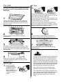
1
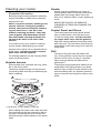
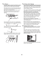
Gas
Users Guide
Installation & Service Instructions
U102220-07
Be safe
Warning
Accessible parts will become hot in use. To avoid burns
and scalds children should be kept away.
You need clean fresh air - so does your cooker. Burner flames
produce exhaust gases, heat and moisture. Make sure that the
kitchen is well ventilated: keep natural ventilation holes open or
install a powered cooker hood that vents outside. If you have
several burners on or use the cooker for a long time, open a
window or turn on an extractor fan. For more detail see the
Installation Instructions.
We recommend you read the ‘General Safety Instructions’
section if you have not used a gas cooker before. We describe
some basic guidelines on how to use a gas cooker safely.
Gas and Electricity on
Make sure that the gas supply is turned on and that the cooker
pluged in to the electricity supply and switched on. The cooker
needs electricity.
Peculiar smells
When you first use your cooker it may give off a slight odour.
This should stop after a little use.
Before using for the first time, make sure that all
packing materials have been removed and then to dispel
manufacturing odours, turn the ovens to Mark 7 and run for
an hour.
Make sure the room is well ventilated to the outside air, by
opening windows or turning on a cooker hood for example.
We recommend that people with respiratory or allergy
problems should vacate the area for this brief period.
Before using the grill for the first time you should also
turn on the grill and run for 30 minutes with the grill pan in
position, pushed fully back, and the grill door open.
Installation
In the UK the cooker must be installed by a CORGI registered
engineer. Failure to install the appliance correctly could
invalidate any warranty or liability claims and lead to prosecution
This appliance shall be installed in accordance with the
regulations in force and only in a well ventilated space. Read the
instructions before installing or using this appliance.
This appliance should not be installed in a boat or caravan.
2
Contents
Hotplate burners
Page 4
The Griddle
Page 5
Warmer
Page 5
The Grill
Page 6
The Ovens
Page 7
The Clock
Page 7
Cooking using the timer
Page 9
Oven cooking
Page 10
‘S’ (Slow) cooking
Page 10
Oven shelves
Page 11
The Handyrack
Page 12
Oven light
Page 12
Storage
Page 12
Oven cooking guide
Page 13
Cleaning your cooker
Page 14
Moving your cooker
Page 17
Troubleshooting
Page 18
General Safety Instructions
Page 20
Installation
Page 22
Servicing Notes
Page 29
Circuit Diagram
Page 34
Technical Data
Page 35
3
Hotplate burners
Simmering aids, such as asbestos or mesh
5
mats, are NOT recommended. They will reduce
burner performance and could damage the pan
1
supports.
Some models have a glass lid over the hotplate.
If it is not open, lift it up at the front.
There is a safety device which cuts off the gas to the
hotplate burners if the lid is accidentally closed with
a burner on. The gas supply is restored when the lid
is raised.
The toughened glass lid is not intended as a
work surface and should not be used for this
purpose.
Avoid using unstable and misshapen pans that
6
may tilt easily and pans with a very small base
diameter e.g. milk pans, single egg poachers. The
Before closing the lid remove all pans from the
hotplate and ensure that all hotplate control knobs
are in the off position.
minimum pan diameter recommended is 120mm.
Pans and kettles with down turned base rims should
not be used.
The drawing by each
2
knob indicates which
burner that knob controls.
Note.
If you leave the gas taps in the ‘On’ position
when the lid has been closed, unburnt gas will
escape when the lid is raised.
Press the igniter button,
and push in and turn a knob
to the large flame symbol
( ). Alternatively light with a
match.
When the spark button (IGN) is pressed, sparks
will be made at every burner, this is normal.
If a burner flame goes out, turn the control knob off
and leave it for one minute before relighting it.
You can remove the burner parts for
cleaning, see the ‘Cleaning your cooker’
section of these instructions.
the flame height to
3 Adjust
suit by turning the knob.
You should wipe the enamel top surface of the
cooker around the hotplate burners as soon as
possible after spills occur. Try to wipe them off
while the enamel is still warm.
On this cooker the low
position is beyond high, not
between high and off. The
small flame marks the ‘low
position’.
Turn the knob towards it after the contents of a pan
have boiled.
sure flames are under the pans. Using a
4 Make
lid will help the contents boil more quickly.
Pans and kettles with concave bases or down turned
base rims should not be used.
4
The Griddle
5
Always leave space around the griddle for the
gases to escape. Never fit two griddles side by side.
Large pans should also be spaced well apart. The
maximum pan base diameter is 250mm.
1
The griddle fits a single pan support, front to back.
It is designed for cooking food on directly. Don’t use
pans of any kind on it. The griddle surface is nonstick and metal cooking utensils (e.g. spatulas) will
damage the surface. Use heat resistant plastic or
wooden utensils.
Use the following heat settings as a guide for
griddle cooking.
High/medium:
Drop scones, Bacon, Chops, Steak, Burgers.
Medium/low:
Potato cakes, Eggs, Fish cakes.
2
Don’t put it crossways - it will not fit properly and will
be unstable.
Experience will soon familiarise you with the
correct setting to use for cooking.
Don’t put it on the High burner - it is not designed to
fit the Wok burner pan support.
After cooking allow the griddle to cool before
cleaning.
Warmer
3
Position the griddle over the hotplate burners
resting on the pan support. The griddle can be
lightly brushed with cooking oil before use. Light the
hotplate burners. Adjust the flame heights to suit.
Use the warmer for keeping food warm while the
final touches are put to a meal. Turn the control
knob anti-clockwise to the on position. The ‘HOT’
indicator lights up. For best results, pre-heat
a covered serving dish for 10 minutes before
adding food to it.
CAUTION:- If a crack in the Warmer surface
becomes visible, due to accidental damage etc.,
isolate the appliance from the electricity supply
immediately by turning it off at the wall and
arrange for its repair.
4
Preheat the griddle for a maximum of 5 minutes
before adding food. Leaving it longer may cause
damage. You can reduce the heat by turning the
control knobs towards the lower position (marked
with the small flame symbol).
DO NOT RECONNECT THE COOKER TO THE
ELECTRICITY SUPPLY UNTIL AFTER REPAIR!
5
LP Gas
The Grill
5
CAUTION: Accessible parts may be hot when
the grill is in use. Young children should be
kept away.
The grill has a special safety device with stops the
flow of gas to the grill if the flame goes out. Turn the
knob to the large flame symbol ( ).
Press the igniter button. Press in the grill knob - this
lets gas through to the burner. Keep holding the grill
knob pressed for about 10 seconds.
1
The burner does not glow red - food cooks from
the heat of the flame. The first time you light the
grill there may be a little smoke given off - this is
perfectly normal.
If when you let go of the control knob the burner
goes out, the safety device has not held in. Turn off
the grill and wait one minute then try again this time
holding in the button for slightly longer.
2
6
Remove the pan from the bottom of the grill
compartment.
The low position, marked with the small flame
symbol, is beyond high, not between high and off.
3
7
After placing your food on the grill tray pan, slide
the grill pan onto the side supports just below the
burners. Make sure it is pushed right in and touches
the back stop.
The grill pan grid can be turned over to give two
grilling positions.
4
For best results, especially on toast, preheat the
grill with the grill pan in the cooking position for
two minutes before use. The grill trivet can be
removed and the food placed on it while you are
waiting for the grill to preheat. After placing your
food on the grill pan grid, slide the grill pan onto
the side supports just below the burners. Adjust
the flame height to suit by turning the knob.
Make sure the grill pan is pushed right in and
touches the back stop. Never close the grill door
while the grill is on.
Natural gas
5
Press the igniter
button and press
in and turn the grill
knob to the large
flame symbol ( ).
When the flame lights
release the igniter
button.
Don’t leave the grill on for more than a few
moments, without the grill pan underneath it.
You can brown the top of dishes cooked in the
oven, under the grill. Remove the grill trivet and
place the dish onto the base of the grill pan.
Slide the grill pan along the floor of the grill
cavity.
6
The Ovens
The clock must be set to the time of day before
the ovens will work. See ‘The Clock’ section of
these instructions for how to set the clock.
Before using for the first time, to dispel
manufacturing odours turn the ovens to
Mark 7 and run for an hour. Make sure the
room is well ventilated to the outside air, by
opening windows or turning on a cooker
hood for example. We recommend that
people with respiratory or allergy problems
should vacate the area for this brief period.
4
Dishes cooking on the central shelf will cook at the
gas mark indicated on the knob.
5
Dishes placed above the central position will be
cooked at approx. one gas Mark higher, dishes
cooked below approx. one gas Mark lower. You can
therefore cook dishes requiring different gas Marks
at the same time.
1
Push in and turn the knob controlling the oven to
Gas Mark 9. The oven will light automatically.
6
The ‘S’ setting is a very low temperature for slow
cooking, overnight or while you are out or at work.
The ‘S’ setting can also be used for keeping food
warm.
2
Turn the control knob back to the Mark you wish to
cook on and for best results pre-heat for 15 minutes
before placing your dishes in the oven.
The Clock
You can use the timer to turn the ovens on and
off. The clock must be set to the time of day
before the ovens will work.
To set the time of day
3
Press and hold as shown.
At the same time, press
(-) or (+) until the correct
time shows.
The ovens use our special ‘Heatflow’ system.
Because the oven burner is not hidden under the
oven base you will see the burner flames at the back
of the oven - this is perfectly normal.
Don’t forget it’s a 24 hour
clock.
The oven is protected by a safety cut off, which
reduces the supply of gas to the oven if the flames
go out, e.g. an interruption to the mains supply.
Initially the gas will burn with a small flame but after
approximately one minute the flame will become
larger indicating that the oven is full on.
If you make a mistake or press the wrong button,
turn off the power supply for a minute or two and
start again.
7
If the key symbol ( ) appears on the left of the
display you have accidentally turned on the
key lock feature. See the section ‘Clock Special
Features’.
To time something that’s cooking
(minute minder)
To start and stop the oven
automatically
Before you set the clock, you must have two
numbers clearly in mind.
The ‘cook period’, which is the period of time
you want the oven to cook.
Press and hold the
Minute Minder ( ).
The ‘stop time’, which is the time of day you
want the oven to stop cooking.
You cannot set a start time directly - this is set
automatically by setting the cooking period and
stop time.
At the same time
press (-) or (+) until
the time you want to
cook for is shown.
Press and hold the
Cook Time ( )
button. At the same
time press (-) or (+)
until your required
‘cook period’ shows.
You can check time remaining by pressing
and cancel the beeper by pressing
To stop automatically
Press and hold the
Stop Time ( )
button.
Use when you have started the oven manually.
At the same time
press (-) or (+) until
your required ‘stop
time’ shows.
Press and hold the
Stop Time ( )
button.
AUTO will show in the
display.
At the same time press (-) or (+) until your
required ‘Stop Time’ shows. AUTO will show in
the display. When your cooking is finished the
beeper sounds. TURN THE OVEN KNOB TO
0 FIRST, then press once to stop the beep,
press again to return to manual cooking.
Set the oven to the required temperature. When
your cooking is finished the beeper sounds.
TURN THE OVEN KNOB TO 0 FIRST, then
press once to stop the beep, press again to
return to manual cooking.
If you are out, don’t worry about the beeper
going off, it stops after a while. When you return,
TURN THE OVEN KNOB TO 0 FIRST, then
press twice, to return to manual cooking.
AUTO is showing, you want to
reset to manual cooking.
When cancelling an automatic setting, any
cooking time already set must be returned
to 0.00 before you can return to manual, by
pressing the button.
8
Clock Special Features
Cooking using the timer
Key Lock
When the key lock is activated, the clock can be
operated as usual but the oven is locked and will
not come on. This means that your child could
select a cook program but the program will not
be activated and oven will not be switched on.
The timer can be used to turn just one oven
or both on and off automatically. The start and
stop time must be the same for both ovens but
different cooking temperatures can be set.
If you want to turn one of the ovens on
at the same time as the timer is set for
automatic cooking, you must wait until
the timer has turned on the oven/ ovens
first. Then you can adjust either of them
manually in the normal way.
To activate the key lock
Make sure that the clock is in manual mode and
cancel any active programs.
Hold the
Minute Minder ( )
and Cooktime ( )
buttons for about 8
seconds.
You can set the oven to turn on any time over
the following 24 hour period
If you want to cook more than one dish,
choose dishes that require approximately
the same time. However, dishes can be
‘slowed down’ slightly by using small
containers and covering them with
aluminium foil, or ‘speeded up’ slightly by
cooking smaller quantities or placing in
larger containers.
‘On’ will appear on the
display.
Press the ‘+’ button
once.
‘Of’ will appear on the
display.
Very perishable foods such as pork or fish
should be avoided if a long delay period is
planned, especially in hot weather.
The clock oven
control functions are
now locked.
Don’t place warm food in the oven.
Don’t use an oven already warm.
Don’t use if an adjoining oven is warm.
After a few seconds
the display will revert
to show the time
of day and the key
symbol ( ).
Avoid using wine or beer if there is a delay
period, as fermentation may take place.
To avoid curdling, cream should be added to
dishes just before serving.
Fresh vegetables, which may discolour during a
delay period, should be coated in melted fat or
immersed in a water and lemon juice solution.
To turn off the key lock
Hold the
Minute Minder ( )
and Cooktime ( )
buttons for about 8
seconds.
Many frozen foods are ideal for delayed
cooking and can be placed in the oven while
still frozen.
‘Of’ will appear on the
display.
Fruit pies, custard tarts or similar wet mixtures
on top of uncooked pastry are only satisfactory if
there is a short delay period. Dishes containing
leftover cooked meat or poultry should not be
cooked automatically if there is a delay period.
Press the ‘+’ button
once. ‘On’ will appear
on the display.
Whole poultry must be thoroughly defrosted
before placing in the oven.
Check that meat and poultry are fully
cooked before serving.
After a few seconds the display will revert to
show the time of day.
The oven and the clock oven control functions
can now be used normally.
9
Oven cooking
‘S’ (Slow) cooking
The wire shelves should always be pushed
firmly to the back of the oven.
Baking trays with food cooking on them should
be placed level with the front edge of the oven’s
wire shelves. Other containers should be placed
centrally. Keep all trays and containers away
from the back of the oven, as overbrowning of
the food may occur.
The ‘S’ setting is a very low temperature for
slow cooking, overnight or while you are out
or at work. The ‘S’ setting can also be used for
keeping food warm.
For even browning, the maximum recommended
size of a baking tray is 325mm (123/4”) by
305mm (12”).
You can cook on ‘S’ throughout, or use a 30
minute ‘boost’ period at gas Mark 6 and then ‘S’
cook.
When the oven is on, don’t leave the door open
for longer than necessary, otherwise the knobs
may get very hot.
When roasting joints, poultry or pot
roasting, always cook at Mark 6 for 30
minutes at the beginning of the cooking
period.
• Always leave a ‘fingers width’ between dishes
on the same shelf. This allows the heat to
circulate freely around them.
• To reduce fat splashing when you add
vegetables to hot fat around a roast, dry them
thoroughly or brush lightly with cooking oil.
• Where dishes may boil and spill over during
cooking, place them on a baking tray.
The oven is protected by a safety cut off, which
reduces the supply of gas to the oven if the
flames go out, e.g. an interruption to the mains
supply.
You can ‘S’ cook for periods of 6 to 12 hours.
This technique is particularly useful if you want
to cook a dish overnight or while you are out at
work during the day.
• Plates can be warmed in the oven on the ‘S’
setting. The ‘S’ setting can be used to keep
foods hot for 3-4 hours after ‘normal’ cooking,
without drying out or overbrowning.
• The Cook & Clean oven liners (see Cleaning
your cooker) work better when fat splashes
are avoided. Cover meat when cooking.
• Sufficient heat rises out of the oven
while cooking to warm plates in the grill
compartment.
• If you want to brown the base of a pastry dish,
preheat the baking tray for 15 minutes before
placing the dish in the centre of the tray.
Poultry and rolled joints should not be stuffed
before cooking. The stuffing should be cooked
separately. Poultry and pork should be cooked
in the top half of the oven, and other meats not
lower than shelf position 4.
Frozen foods must be thoroughly
thawed out before ‘S’ cooking.
Whole poultry should not be cooked on ‘S’.
Chicken casseroles are fine.
Casseroles must be brought to boiling
point on the hotplate immediately before
‘S’ cooking.
A roasting joint should be covered with
cooking foil, or with a roasting bag to
reduce shrinkage and retain juices.
Should further browning be necessary, uncover
the meat and increase the temperature to Mark
4 for a short period.
Cut root vegetables into small pieces
unless cooking whole, e.g. jacket
potatoes.
Cover dishes tightly with a lid or foil to prevent
evaporation and transfer of flavour.
10
Once the oven has been loaded and
the ‘S’ setting is in operation resist
the temptation to open the oven door.
Heat will be lost and the cooking time
extended.
Oven shelves
A meat thermometer is recommended for
checking that a joint or poultry is sufficiently
cooked. Insert the probe through the thickest
part of the meat. The temperatures to be
expected are as follows.Beef rare
60°C / 140°F
medium
71°C / 160°F
well done
77°C / 170°F
Lamb
82°C / 180°F
Pork fresh
88°C / 190°F
cured
77°C / 170°F
Poultry
90°C / 195°F
Veal
77°C / 170°F
the shelf guard should be at the back pointing upwards
The oven shelves can be easily removed and
refitted.
Pull the shelf forward
until the back of the
shelf is stopped by the
shelf stop bumps in the
oven sides.
Lift up the front of the
shelf so the back of the
shelf will pass under the
shelf stop and then pull
the shelf forward.
To refit the shelf, line up the shelf with a groove
in the oven side and push the shelf back until
the ends hit the shelf stop. Lift up the front so the
shelf ends clear the shelf stops, and then lower
the front so that the shelf is level and push it fully
back.
11
The Handyrack
Oven light
The maximum weight that can be held by the
Handyrack is 5.5kg (12lb). It should only be used
with the supplied meat tin, which is designed
to fit the Handyrack. Any other vessel could be
unstable.
Press the appropriate button to turn on one of
the oven lights.
If one of the oven lights fail, turn off the
power supply before you change the bulb.
See the ‘Troubleshooting’ section for details
on how to change an oven light bulb.
The Handyrack fits to the left hand oven door
only. Food cooking on it is easy to attend to,
because it’s accessible when the door is open. It
can be fitted at two different heights. One of the
oven shelves must be removed and the other
positioned to suit.
Storage
When the Handyrack is used in its highest
position, other dishes can be cooked on the
bottom shelf position of the oven or standing on
the base of the oven
When the Handyrack is used in its lowest
position, other dishes can be cooked on the
second shelf position of the oven.
The bottom drawer is for storing oven trays and
other cooking utensils. It can get very warm,
don’t store anything in it that may melt or catch
fire. The drawer can be removed completely by
pulling it right out and up.
To fit the Handyrack,
locate one side of it on
the door bracket.
Then spring the other
side out to clip it onto
the other bracket.
The oven control settings and
cooking times given opposite
are intended to be used only as a
guide. Individual tastes may require
the temperature to be altered to
provide a preferred result.
Always leave at least one runner space
between shelves when 2 tier cooking.
Place baking trays, individual cake
tins or baking dishes centrally on the
oven shelf. For best results pre-heat
the oven for 15 minutes.
12
Oven cooking guide
Gas Shelf Position
Mark from Top Approximate Cooking Time
Meat
Beef (no bone)
Thoroughly thaw frozen joints
before cooking. Meat may be
roasted at Mk. 7 and the cooking
time adjusted accordingly. For
stuffed and rolled meats, add
approx. 10 min. per 500g. or
cook at Mk. 6 or 20min, then
Mk. 3 for the remainder.
3
3-4
30-35mins. per 500g.+30-35 mins.
6
3-4
20-25mins. per 500g.+20-25 mins.
3
3-4
30-35mins. per 500g.+30-35 mins.
6
3-4
25-30mins. per 500g.+25-30 mins.
3
2-3
35-40mins. per 500g.+35-40 mins.
6
3-4
25-30mins. per 500g.+25-30 mins.
3
3-4
20-25mins. per 500g.+20-25 mins.
6
3-4
15-20mins. per 500g.+15-20 mins.
3
3-4
25-30mins. per 500g.+25-30 mins.
6
3-4
20mins. per 500g.+20 mins.
3
4
20mins. per 500g.+20 mins.
6
4
15mins. per 500g.+15 mins.
3
4
25-30mins. per 500g.
6
4
20mins. per 500g.
1-2
3-4
7
2
Large tin 30-35 mins. Individual, 10-20 mins.
5
2
Fillets 15-20 mins. Whole 15-20mins. per 500g.
5
2
Steaks according to thickness.
Very rich fruit - Christmas
/ wedding etc.
1
4
45-50mins. per 500g. of mixture.
Fruit 180mm tin
2
4
2 to 21/2 hours.
Fruit 230mm tin
2
4
Up to 31/2 hours.
Madeira 180mm
3
4
80-90 mins.
Queen cakes
5
2 & 4 or 3
15-25 mins.
Scones
7
2 & 4 or 3
10-15 mins.
180mm tin
4
2 & 4 or 3
20-30mins.
230mm tin
4
2 & 4 or 3
30-40 mins.
Shortcrust tarts
6
2&4
Fruit pies
6
2-3
35-45 mins.
Tartlets
6
2-3
10-20 mins. according to size.
Flaky/rough puff
7
2-3-4
20-40 mins. according to size.
Puff pastry
8
2-3-4
20-40 mins. according to size.
Meringues
‘S’
3
11/2 to 2 hrs.
Baked egg custard
3
3
45-60 mins.
Baked sponge pudding
5
3
40-45 mins.
1-2
3
2-3 hrs.
Lamb
Pork and Veal
Poultry
Chicken (2.3kg)
Turkey (4.5kg)
Turkey (over 4.5kg)
Duck/ duckling
Casseroles
Yorkshire Pudding
Fish
For stuffed poultry, you could
cook at Mk. 6 for 20mins. and
then Mk.3 for remainder. Don’t
forget to include the weight
of the stuffing. For fresh or
frozen prepacked poultry,
follow instructions on the pack.
Thoroughly thaw frozen poultry
before cooking.
2-4 hours according to recipe.
Cakes
Victoria sandwich
Desserts
Milk pudding
40-60 mins. on pre-heated tray.
13
When two tier cooking leave at
least one runner space between
shelves. Position the baking tray
with the front edge along the
front of the oven shelf.
Rich fruit cakes made with selfraising flour should be cooked
on Mk.4 for the first half hour at
least and then finished at the
setting shown.
If cooking more than one tart at
the same time, swap them over
at approx. 25 mins. For even
browning the maximum size of
baking tray recommended is
325mm x 305mm. This ensures
free heat circulation.
If cooking a two tier load, when
the top tray is removed, the tray
in the lower position should be
raised to the higher shelf, or
the trays interchanged, for the
remaining cooking time.
Cleaning your cooker
Griddle
Always clean the griddle after use. Allow to
cool completely before removing. Immerse the
griddle plate in hot soapy water. Use a soft
cloth or, for stubborn stains, a nylon washing up
brush.
Essential information
Before thorough cleaning isolate the electricity
supply. Remember to switch on the electricity
supply before use.
Never use paint solvents, washing soda,
caustic cleaners, biological powders,
bleach, chlorine based bleach cleaners,
coarse abrasives or salt. Don’t mix
different cleaning products - they may
react together with hazardous results.
Recommended cleaning materials are
shown in the table at the end of this
section.
NEVER USE CAUSTIC OR ABRASIVE
CLEANERS AS THESE WILL DAMAGE THE
SURFACE.
Control Panel and Doors
The control panel and control knobs should
only be cleaned with a soft cloth wrung out
in clean hot soapy water - but take care that
no surplus water seeps into the appliance.
Wipe with a clean dampened cloth then polish
with a dry cloth. The oven doors should only be
cleaned with a soft cloth wrung out in clean hot
soapy water.
If you want to move your cooker for cleaning,
see the section called ‘Moving your cooker’.
All parts of the cooker can be cleaned with hot
soapy water - but take care that no surplus
water seeps into the appliance.
Grill
The face of the grill burner will darken with
use - this is perfectly normal. Any fat or grease
will burn off. Do not try to clean it - the small
holes could get blocked and affect burner
performance.
For cleaning materials see the ‘Cleaning Table’
at the end of this section.
Hotplate burners
Some models have a separate trim ring, which
fits on the burner head.
The grill pan and grid should be washed in hot
soapy water. After grilling meats or any foods
that soil, leave to soak for a few minutes in the
sink immediately after use. Stubborn particles
may be removed from the grid by using a nylon
brush.
The burner heads and caps can be removed
for cleaning. Make sure they are absolutely dry
before replacing.
A cap, B head, C notch, D base, E electrode
When refitting the burner head, make sure that
the notch lines up with the electrode or hole in
the base. Check that the burner head is level
and that the cap is fitted centrally on the burner
head.
14
The Ovens
The Oven side linings
Cleaning is easier if carried out while the oven is
still warm. Before cleaning, cover the burner to
prevent the burner holes becoming blocked.
The oven has removable oven side lining panels
that have been coated with special enamel that
partly cleans itself. This does not stop all marks
on the lining, but helps to reduce the amount of
manual cleaning needed.
The inside of the oven and inner door panel can
be cleaned using an approved cleaner see the
table at the end of this section.
The Cook & Clean panels work better above
gas Mark 6. If you do most of your cooking
below this temperature, occasionally
remove the panels and wipe with a lint
free cloth and hot soapy water. The panels
should then be dried and replaced and the
oven heated at Gas Mark 7 for about one
hour. This will ensure the Cook & Clean
panels are working effectively.
Take care not to disturb the oven thermostat
temperature sensor at the top of the oven
opening.
Don’t use steel wool (Brillo) or any other
materials that will scratch the surface. Don’t use
oven cleaning pads.
Before cleaning the oven, cover the burner at
the rear to stop the holes getting blocked as you
clean. If they are accidentally blocked, clean
them out with thin wire, such as fuse wire.
The enamelled oven burner trim (supplied with
some models only) can be removed for cleaning.
The oven burner trim hooks onto the front of the
oven burner bracket.
Removing the Oven Linings
The lining panels can be removed for cleaning
and for cleaning behind. Remove the shelves
first.
Each side of the oven is fixed with four fixing
screws. You don’t have to remove the screws
to remove the oven linings. Lift each side panel
upwards and they will slide off the screws. Then
pull them forwards.
When refitting make sure that the trim is in the
middle of the front of the oven burner bracket.
Once the linings are removed, the oven enamel
interior can be cleaned.
15
Cleaning Table
Hotplate
Part
Hotplate Top
Pan Supports, Wok Cradle
(some models only)
Warming Zone (some models
only)
Burner Caps
Burner Trim Rings (some
models only) and Burner Head
Griddle Plate (some models
only)
Finish
Enamel or
Stainless Steel
Enamel coated
Cast Iron or
Recommended Cleaning Method
Hot soapy water, soft cloth. Any stubborn stains
remove gently with a nylon scourer.
Cif Cream Cleaner- Faberge Lever and a nylon
scourer.
Stainless Steel
Toughened
Glass
Enamel
Aluminium
Dishwasher.
Hot soapy water, cream cleaner/scourer if necessary.
Non-Stick
Surface
Cream cleaner, nylon scourer. Dishwasher
Cif or other cream cleaner with a soft cloth. Be careful
not to be over vigorous.
Allow to cool. Wash in hot soapy water. Do not use
abrasive cleaners/scourers. Dishwasher.
Outside of cooker
Part
Door, Door surround and
Storage Drawer exterior.
Finish
Enamel or paint
Stainless Steel
Sides and Plinth
Splashback/Rear Grille
Control panel
Control Knobs/Handles
Oven Door Glass/Glass Lid
Painted surface
Enamel or
Stainless Steel
Paint, Enamel or
Stainless Steel
Plastic/ Chrome
Toughened glass
Recommended Cleaning Method
Hot soapy water, soft cloth.
Any stubborn stains, remove gently with a liquid
detergent.
E Cloth (Comet) or Vileda Microfibre Plus All
Purpose Cloth Freudenberg Household Products LP
(supermarket)
Hot soapy water, soft cloth
Hot soapy water, soft cloth. Cream cleaner, with care, if
necessary.
Warm soapy water. Do not use abrasive cleaners on
lettering.
Warm soapy water, soft cloth.
Hot soapy water, cream cleaner/scourer if necessary.
Oven and Grill
Part
Sides, floor & roof of oven -
Finish
Enamel
NOT COOK & CLEAN OVEN
PANELS (see below)
Recommended Cleaning Method
Any proprietary oven cleaner that is suitable for enamel.
CAUTION: CORROSIVE/CAUSTIC OVEN CLEANERS
- FOLLOW MANUFACTURERS INSTRUCTIONS.
Protect the burner in gas ovens with foil whilst cleaning
the oven interior. Make sure you remove the foil
before using the oven.
Cook & Clean Oven Panels
Special enamel This surface cleans itself at Mk. 7 and above, or the
(some models only)
that partly
panels can be removed and washed with hot soapy
cleans itself
water and a nylon brush. (see ‘The Ovens’ in ‘Cleaning
your cooker’)
Oven Shelves, Handyrack,
Chrome
An oven interior cleaner that is suitable for chrome.
Grill Trivet.
Soap filled pad. Dishwasher.
Grill Pan, Meat Tin.
Enamel
Hot soapy water. Soap filled pad (Brillo). Dishwasher.
Regular cleaning is recommended. For easier
Cleaners listed are available from
cleaning, wipe up any spillages immediately.
Supermarkets or electrical retailers as stated.
Cleaner manufacturer in Italics
To help keep your oven clean, cover meat when
roasting, with foil or use a roasting bag. Brush
vegetables with fat before placing around the
meat.
For enamelled surfaces use a cleaner that
is approved for use on vitreous enamel. The
vitreous enamel association has a list of
approved cleaners. Contact them via their
website www.ive.org.uk or telephone: 01527
893031.
16
Moving your cooker
Switch off the electricity supply.
The cooker is heavy, two people may be
required to move it. The cooker is fitted with
one roller at the front and two at the back.
There are also two screw down levelling feet
at the front.
The front roller, designed for moving the cooker
can be wound down. The levelling tool that
controls this roller is in the storage drawer
compartment.
Move the oven a bit at a time, checking behind
it to make sure the gas hose is not caught.
Make sure both electricity and gas cables have
sufficient slack to move the cooker forward as
you go along.
If a stability chain is fitted, release it as
you ease the cooker out.
Remove the storage drawer (by pulling it
right out and lifting it up slightly) and you
should see the levelling tool.
When you replace the cooker, wind it down
off the rollers by turning the levelling tool anticlockwise. This is important. It will stop the
cooker moving accidentally, while in use.
When you replace the cooker, wind it down
off the rollers by turning the levelling tool anticlockwise. This is important. It will stop the
cooker moving accidentally, while in use.
Your installer may not have left the levelling tool
in place. If not, locate it as shown. If you cannot
find the levelling tool, contact your installer. See
the Installation section of these instructions
where your installer should have written their
contact details.
Turn the levelling tool clockwise, two full
(180°) turns. It will be stiff. The front of the
oven will rise slightly as the roller drops
down.
Open the grill door and right hand oven door so
that you can get a good grip on the bottom of
the fascia panel as you move the oven.
Do not move the oven by pulling the hand
rail, door handles or knobs.
17
Troubleshooting
Hotplate ignition or hotplate
burners faulty
Oven ignition faulty
Is the power on? Is the clock running? - if not
there may be something wrong with the power
supply.
See the section on ‘Checking the power supply’.
Check that the electrode and burner slots are
not blocked by debris.
Has the Timer been set to auto by mistake, or
after power cut?
Has the Timer been set correctly but oven tap
not left OFF by mistake?
Is the power on? Is the clock illuminated? If not
there maybe something wrong with the power
supply.
See ‘power supply’ section further on.
Are the sparker (ignition electrode) or burner
slots blocked by debris?
Is the burner trim correctly located?
Are the burner caps correctly located?
See the section entitled ‘Cleaning your cooker’
Is the key symbol ( ) showing in the display?
See the Clock section of the instructions for
more information on the key lock feature of the
clock.
Hotplate burners will not light
If only one or all the hotplate burners will not
light, make sure that the parts have been
replaced correctly after wiping or removing for
cleaning.
Check that there is not a problem with your gas
supply. You can do this by making sure that other
gas appliances you may have are working.
Do the burners spark when you push the
button? If not check the power is on - is the clock
illuminated?
Oven not coming on when turned
on manually
Is the power on? Is the clock illuminated? If not
there may be something wrong with the power
supply. Is the cooker supply on at the isolator
switch? Is the clock flashing 0.00? If so set it to
the correct time of day. Has the Timer been set
to AUTO by mistake. If AUTO is showing on the
clock display, press the ‘cook period’ button and
reduce any set cooking time showing to 0.00,
with the (+) and (-) buttons. Press the button
twice.
A crack has appeared in the
Warmer plate’s surface
Disconnect the cooker immediately from the
power supply and arrange for its repair. Don’t
use the cooker until after the repair. See the
HELP leaflet for how to contact a service person.
Is the key symbol ( ) showing in the display?
See the Clock section of the instructions for
more information on the key lock feature of the
clock.
The knobs get hot when I use the
oven or the grill, can I avoid this?
Yes, this is caused by heat rising from the oven
or the grill, and heating them up. Don’t leave
the oven door open. Make sure that the grill pan
is pushed right back to the ‘back stop’ when
grilling.
Oven not coming on when
automatic cooking
Timer set correctly but oven knob left OFF by
mistake?
Is the key symbol ( ) showing in the display?
See the Clock section of the instructions for
more information on the key lock feature of the
clock.
Grill Ignition faulty
Is the power on? Is the clock illuminated? If not
there maybe something wrong with the power
supply. See ‘power supply’ section further on.
Grill not cooking properly
Are you using the pan and trivet supplied with
the cooker? Is the pan being used on the
runners, not the floor of the compartment? Is the
grill tray pushed fully back to stop?
18
The oven is not cooking evenly
Do not use a tin or tray larger than 340mm x
305mm.
If you are cooking a large item, be prepared to
turn it round during cooking.
If two shelves are used, check that space has
been left for the heat to circulate. When the
baking tray is put into the oven, make sure it is
placed centrally on the shelf.
Check that the door seal is not damaged and
that the door catch adjusted so that the door is
held firmly against the seal.
NB the seal is intended to have a gap at the
bottom of the door
A dish of water when placed on the shelf should
be the same depth all over. (For example, if it is
deeper at the back, then the back of the cooker
should be raised up or the front lowered). If the
cooker is not level arrange for your supplier to
level it for you.
The oven light is not working
The bulb has probably blown. You can buy a
replacement bulb (which is not covered under
the guarantee) from a good electrical shop. Ask
for an Edison screw fitting 15w 230v lamp, FOR
OVENS. It must be a special bulb, heat resistant
to 300°C.
Open the oven door and remove the Handyrack
(if fitted) and oven shelves.
Turn off the power supply.
Unscrew the bulb cover by turning anticlockwise.
Unscrew the old bulb. Screw in the new bulb,
screw back the bulb cover. Turn on the electricity
supply and check that the bulb now lights.
Power supply - You think there
may be a problem with it
First check the socket by trying out another
piece of electrical equipment in it.
If that works, replace the fuse in the cooker plug.
Use a 3 amp fuse.
Food is cooking too slowly, too
quickly, or burning
Cooking times may differ from your previous
oven. The oven control settings and cooking
times are intended to be used only as a guide.
Individual tastes may require the gas mark to
be altered one gas Mark either way, to get the
results you want. Try cooking at a higher shelf
position and/or higher Mark. Oven cooking times
and temperatures may need to be increased
when other burners are in use. Are the oven
burner ports blocked with spilt food?
Power failure
In the event of a failure in the electrical supply
the hotplate may be lit using a match.
If there is an installation problem
and I don’t get my original
installer to come back to fix it who
pays?
You do. Service organisations will charge for
their call outs if they are correcting work carried
out by your original installer. It’s in your interest
to track down your original installer.
Oven temperature getting hotter as
the cooker gets older
If turning the knob down has not worked or only
worked for a short time then you may need
a new thermostat. This should be fitted by a
service person.
What cleaning materials are
recommended for the cooker?
See the ‘Cleaning your cooker’ section for
recommended cleaning materials. We do not
recommend Mr. Muscle, as it contains chemicals
that may damage the surfaces of your cooker.
19
General Safety Instructions
In the UK the cooker must be installed by a
CORGI registered engineer.
Have the installer show you the location of the
cooker control switch. Mark it for easy reference.
Always allow the cooker to cool and then switch
off at the mains and before cleaning or carrying
out any maintenance work, unless specified
otherwise in this guide.
The installation must be in accordance with the
installation instructions and comply with the
relevant regulations and also the local gas and
electricity supply companies’ requirements.
All parts of the cooker become hot with use
and will retain heat even after you have
stopped cooking.
If you smell gas
Don’t turn electric switches on or off.
Don’t smoke
Don’t use naked flames
Do turn off the gas at the meter or cylinder
Do open doors and windows to get rid of the gas
Call your gas supplier.
If you are using natural gas in the UK ring British
Gas - Trans Co on
0800 111 999
Take care when touching cooker, to minimize
the possibility of burns, always be certain that
the controls are in the OFF position and that it is
cool before attempting to clean the cooker. Avoid
touching heating elements.
Use dry oven gloves when applicable using damp gloves might result in steam
burns when you touch a hot surface. Never
operate the cooker with wet hands.
Do not use a towel or other bulky cloth in place
of a glove. They might catch fire if they touch a
hot surface.
DO NOT SPRAY AEROSOLS IN THE VICINITY
OF THIS APPLIANCE WHILE IT IS IN
OPERATION.
WHERE THIS APPLIANCE IS INSTALLED IN
MARINE CRAFT OR IN CARAVANS, IT SHALL
NOT BE USED AS A SPACE HEATER.
Clean with caution. If a wet sponge or cloth
is used to wipe spills on a hot surface,
be careful to avoid steam burns. Some
cleansers can produce noxious fumes if
applied to a hot surface.
This appliance is designed for domestic
cooking only. Use for any other purpose
could invalidate any warranty or liability
claim.
Do not use unstable saucepans and position the
handles away from the edge of the hotplate.
The appliance is not intended for unsupervised
use by young children or infirm persons.
Babies, toddlers and young children should not
be allowed near the cooker at any time. They
should never be allowed to sit or stand on any
part of the appliance. Teach them not to play
with controls or any other part of the cooker.
The use of a gas cooking appliance results in
the production of heat and moisture in the room
in which it is installed. Ensure that the kitchen
is well ventilated: keep natural ventilation holes
open or install a mechanical ventilation device,
(mechanical extractor hood).
Prolonged intensive use of the appliance
may call for additional ventilation, for example
opening a window, or more effective ventilation,
for example increasing the level of mechanical
ventilation where present.
Never store anything of interest to children in
cabinets above a cooker - children climbing on
the cooker to reach them could be seriously
injured.
The cooker should be serviced by an Authorised
Person and only approved spare parts used.
In the interests of hygiene and safety the cooker
should be kept clean at all times as a build up in
fats and other food stuff could result in a fire.
Clean only parts listed in this guide.
Always keep combustible wall coverings or
curtains etc. a safe distance away from your
20
cooker. For more detail see the Installation
section of these instructions.
cooker) for warming plates, dishes, drying
tea towels or softening butter.
Do not store or use flammable liquids or
materials in the vicinity of this appliance.
This includes some cleaning solvents and
chemicals used in dry cleaning.
When using an electrical appliance near the
hotplate, be sure that the cord of the appliance
does not come into contact with the hotplate.
If you find a crack in the Warmer surface
immediately disconnect the appliance from
the supply and arrange for its repair.
Do not use water on grease fires. Never pick up
a flaming pan. Turn the controls off. Smother a
flaming pan on a surface unit by covering the
pan completely with a well fitting lid or baking
tray. If available use a multipurpose dry chemical
or foam-type fire extinguisher.
Take care that no water seeps into the appliance
Never leave the hotplate unattended at high
heat settings. Pans boiling over can cause
smoking and greasy spills may catch on fire.
Never wear loose-fitting or hanging clothes while
using the appliance. Be careful when reaching
for items stored in cabinets over the hotplate.
Flammable material could be ignited if brought
in contact with a hot surface unit and may cause
severe burns.
Take great care when heating fats and oils,
as they will ignite if they get too hot.
Only certain types of glass, glass-ceramic,
earthenware or other glazed containers are
suitable for hotplate cooking; others may
break because of the sudden change in
temperature.
Do not allow anyone to climb, stand or hang
on any part of the cooker.
Do not use aluminium foil to cover shelves,
linings or the oven roof.
Make sure that your kitchen is well
ventilated at all times. Use extractor fans or
hoods when fitted.
Never heat unopened food containers. Pressure
build up may make container burst and cause
injury.
Use a deep fat thermometer whenever possible
to prevent overheating fat beyond the smoking
point.
Never leave a chip pan unattended. Always
heat fat slowly, and watch as it heats. Deep
fry pans should be only one third full of
fat. Filling the pan too full of fat can cause
spill over when food is added. If you use a
combination of oils or fats in frying, stir them
together before heating, or as the fats melt.
Foods for frying should be as dry as possible.
Frost on frozen foods or moisture on fresh
foods can cause hot fat to bubble up and over
the sides of the pan. Carefully watch for spills
or overheating of foods when frying at high or
medium high temperatures. Never try to move
a pan of hot fat, especially a deep fat fryer. Wait
until the fat is cool.
The cooker is designed for cooking foods
only and must not be used for any other
purpose.
The oven should NOT be used for heating the
kitchen, not only does this waste fuel but the
control knobs may become overheated.
When the oven is on DO NOT leave the
oven door open for longer than necessary.
The specification of this cooker should not be
altered.
This appliance is heavy, take care when
moving it.
When the cooker is not in use ensure that the
control knobs are in the off position.
When the grill is on, do not use the top
of the flue (the slot along the back of the
21
Installation
Provision of Ventilation
You must be aware of the
following safety requirements &
regulations
In the UK
Prior to installation, ensure that the local distribution
conditions (nature of the gas and gas pressure) and the
adjustment of the appliance are compatible.
This appliance shall be installed in accordance with the
regulations in force and only in a well ventilated space.
Read the instructions before installing or using this
appliance.
In the UK the regulations and standards are as
follows:In your own interest and that of safety, it is law that all
gas appliances be installed by competent persons.
CORGI registered installers undertake to work to
safe and satisfactory standards. Failure to install the
appliance correctly could invalidate any warranty or
liability claims and lead to prosecution.
This appliance should not be installed in a
boat or caravan.
The cooker must be installed in accordance with:-
All relevant British Standards / Codes of
Practice, in particular BS 5440 Part 2 2000,
or Natural Gas - BS 6172 : 1990 and BS
6891 : 1998
For LP Gas - BS 5482-1:1994 (when the
installation is in a permanent dwelling).
The Gas Safety (Installation and Use)
regulations 1998.
The relevant Building / IEE regulations.
This appliance is not connected to a combustion
products evacuation device. Particular attention shall be
given to the relevant requirements regarding ventilation.
The room containing the cooker should have an air
supply in accordance with BS 5440 Part 2 : 2000. All
rooms require an openable window or equivalent, while
some rooms require a permanent vent in addition to the
openable window. The cooker should not be installed
in a bedsitting room with volume less than 20m3. If it is
installed in a room of volume less than 5m3 an air vent
of effective area 100cm2 is required; if it is installed in
a room of volume between 5m3 and 10m3, an air vent
of effective area 50cm2 is required; while if the volume
exceeds 11m3, no air vent is required.
If there are other fuel burning appliances in the same
room, BS 5440 Part 2 : 2000 should be consulted to
determine the requisite air vent requirements.
Location of Cooker
The cooker may be installed in a kitchen/kitchen diner
but NOT in a room containing a bath or shower.
NOTE:
An appliance for use on LPG shall not be installed in
a room or internal space below ground level. e.g. in
a basement.
All models are supplied set for use on either group H natural gas or for use on LP gas.
They cannot be converted from one gas to the other.
This appliance is designed for domestic cooking only. Use for any other purpose could invalidate any
warranty or liability claim.
22
Dear Installer
Before you start your installation, please complete the details BELOW.
If your customer has a problem relating to your installation they will be able to contact you easily.
Thank you
Installer’s Name
Installer’s Company
Installer’s Telephone number
You will need the following equipment to complete the cooker
installation satisfactorily
STABILITY BRACKET
If the cooker is to be
supplied with gas
through a flexible hose,
a stability bracket or
chain must be fitted.
GAS PRESSURE TESTER FLEXIBLE GAS HOSE
It is important the gas
Must be in accordance
pressure is set correctly
with the relevant
standards. For LP Gas
it should be suitable
for LPG, capable of
50mbar pressure, 70°C
These are not supplied
temperature rise and
by with the cooker but are
carry a red stripe, band
available at most builders
merchants.
or label.
MULTIMETER
(for electrical checks)
Make sure the
installation is electrically
safe.
A hose is not supplied by
with the cooker.
You will also need the following tools:
1.
2.
Electric drill
Masonry drill bit & Rawlplugs
(only required if fitting the cooker on a
stone or concrete floor)
3.
4.
Steel tape measure
Cross head screwdriver
5.
6.
7.
8.
9.
Flat head screwdriver
Spirit level
Pencil
Adjustable spanner
Screws for fitting stability bracket
23
Checking the parts
Positioning the Cooker
The diagrams below show the minimum recommended
distance from the cooker to nearby surfaces.
The hotplate surround should be level with, or above,
any adjacent work surface. Above hotplate level a
gap of 75mm should be left between each side of the
cooker and any adjacent vertical surface.
For non-combustible surfaces (such as unpainted
metal or ceramic tiles) this can be reduced to 25mm.
A minimum space of 650mm is required between
the top of the hotplate and a horizontal combustible
surface.
3 pan supports
Griddle plate
Grill pan and trivet
Levelling tool
Handyrack &
4 main oven shelves
Meat tin
Plinth
*Any cooker hood should be installed in accordance
with the hood manufacturer’s instructions.
Surfaces of furniture and walls at the sides and rear
of the appliance should be heat, splash and steam
resistant. Certain types of vinyl or laminate kitchen
furniture are particularly prone to heat damage and
discolouration. We cannot accept responsibility
for damage caused by normal use of the cooker
to any material that de-laminates or discolours at
temperatures less than 65°C above room temperature.
For safety reasons curtains must not be fitted
immediately behind the cooker.
We recommend a gap of 1110mm between units to
allow for moving the cooker. If a flush fit is required, fit
the cooker up to the unit at one side then fit the unit
the other side. Do not box the cooker in; it must still
be possible to move the cooker in and out for cleaning
and servicing. The cooker should not be placed on a
base.
A clearance of 130mm is required if the cooker is near
a corner of the kitchen to allow the oven doors to open.
Unpacking the Cooker
Do not take any packaging off the cooker until it is
directly in front of the place it is to be installed (unless
it will not fit through a door in its outer packaging).
See the loose unpacking sheet.
24
Moving the Cooker
The cooker is very heavy. Take great care.
We recommend two people manoeuvre the cooker.
Ensure that the floor covering is firmly fixed, or
removed to prevent it being disturbed when moving the
cooker around. You will need the levelling tool.
From the back tilt the cooker forward and remove the
rear half of the polystyrene base pack.
Make sure you lower BOTH REAR ROLLERS. There
are two adjusting nuts, one for each roller, at both the
front bottom corners of the cooker.
Unfold the rear edge of pack base tray. Carefully push
the cooker backwards off the pack base and into
position. Take care not to damage the power cable.
Push the cooker close to its final position, leaving just
enough space to get behind it.
Repeat from the front and remove the front half of the
poly base. Pull the drawer out to its furthest point. Lift it
up and out.
Fit the levelling tool on the rectangular adjuster as
shown below.
Levelling
LOWER THE FRONT ROLLER by doing 14 complete
(360º) turns clockwise. (This means turning and
removing the levelling tool 56 times).
Now LOWER THE TWO REAR ROLLERS.
First fit the levelling tool on the hexagonal adjusting nut
as shown below.
Make 10 complete (360º) turns clockwise. (This means
turning and removing the levelling tool 20 times).
25
You are recommended to use a spirit level on a shelf in
one of the ovens to check for level.
Place the cooker in its intended position taking care
not to twist it within the gap between the kitchen units
as damage may occur to the cooker or the units.
The rollers can be adjusted to level the cooker. To
adjust the height of the rear of the cooker use the
levelling tool supplied to turn the adjusting nuts at the
front bottom corners of the cooker.
Adjust the height of the front roller to level the cooker.
Turn clockwise to raise the cooker and anticlockwise to
lower.
When you are satisfied with the height and level
raise the front of the cooker by one turn of the front
roller adjuster. Screw down the front feet to meet the
floor. Screw the front roller adjuster anticlockwise to
raise the front roller so that the front of the cooker is
supported on the feet, not the front roller, to prevent
accidental movement of the cooker.
Leave the levelling tool on the adjuster with the
handle of the tool facing the rear of the cooker, so
that the customer can use it if they wish to move
the cooker.
Replace the drawer by locating on side runners and
push in.
Fitting a stability bracket
Gas Connection
A stability bracket or chain (not supplied by with the
cooker) should be fitted when the cooker is connected
to a flexible gas supply.
When fitting a stability bracket read these instructions
together with the leaflet supplied with the bracket.
1. Place the cooker in its intended position and level the
cooker.
2. Draw a pencil line 100mm from the front edge of the
levelling feet.
3. Mark the centre line for the bracket by measuring
550mm from the left hand side of the cooker.
view from the rear
A position for gas supply connector
B appliance gas inlet
The Gas supply needs to terminate with a down facing
bayonet. The rear cover boxes limit the position of the
supply point.
Because the height of the cooker can be adjusted and
each connection is different it is difficult to give precise
dimensions. Ideally the house supply bayonet should
be in the shaded area shown in the diagram. Although
a 3ft hose can be used, a 3ft6” or 4ft hose will allow
slightly more flexibility in the positioning of the bayonet
and make moving the cooker easier. The hose should
be fitted so that both inlet and outlet connections are
vertical so that the hose hangs downwards.
The connector is located just below the hotplate level
at the rear of the cooker.
For Natural Gas the flexible hose must be in
accordance with B.S.669.
For LP Gas it should be capable of 50mbar
pressure, 70°C temperature rise and carry a red
stripe, band or label.
If in doubt contact, your supplier.
Screw connect the threaded end of the hose into the
gas inlet in the underside of the connector block on the
back of the cooker.
After completing the gas connection, check the cooker
is gas sound with a pressure test. When checking
for gas leaks do not use washing up liquid - this can
corrode. Use a product specifically manufactured for
leak detection.
4. Lower the front roller and move the cooker forward.
5. Measure back from the pencil line 550mm to locate
the front edge of the bracket. Fix the bracket to the
floor.
6. Measure the height from floor level to engagement
edge in back of cooker. Add 3mm to this dimension
and assemble the stability bracket to this height. (i.e.
from floor level to underside of the top member) and
ensure the bracket does not foul the oven burner
assembly.
26
Pressure testing
The gas pressure can be measured at the injector
of one of the LH hotplate burners. Remove the pan
support, burner head and caps. The injector is now
accessible.
For Natural Gas cookers the pressure should be
20mbar.
For LP Gas cookers the pressure should be
29mbar for Butane
37mbar for Propane.
Reassemble burner top, making sure it is reassembled
in the correct way on the burner body.
Electrical Connection
WARNING: THIS COOKER MUST BE EARTHED.
All external wiring must comply with the IEE
Regulations for the Electrical Equipment of Buildings.
Connection to the electrical supply can be made with
either a plug and socket or be permanently wired via
a double pole switch. The cooker is supplied with a 3
core cable 2m long. If a replacement cable is fitted it
must be 250v high temperature PVC (85°C), 1mm2.
Should the plug not fit the socket in your home, it
should be removed and replaced with a suitable plug.
Note: If a plug is fitted which is not suitable, it must be
cut off and disposed of properly. To avoid the risk of
electrocution, the plug must not be left where children
might find it and plug it into a supply socket.
Three pin plugs to BS1363 with a capacity of not less
than 13A must be used and fitted with a 3 amp fuse
‘ASTA’ approved to BS 1362.
After replacing the fuse the cover must be refitted.
If the cover is lost, the plug must not be used until
a replacement cover has been obtained from your
supplier. The colour of the correct fuse carrier is that of
the coloured insert in the base of the fuse recess, or
stated elsewhere on the plug. Always state this colour
when ordering a replacement fuse carrier.
IMPORTANT The wires in the mains lead are coloured
in accordance with the following code:GREEN AND YELLOW: EARTH
BLUE: NEUTRAL
BROWN: LIVE
The wires should be connected into the terminal of
your plug as shown:
Electrical checks
EARTH CONTINUITY CHECK
The cooker must be disconnected from the power
supply. Set your meter to (ohm) on the X1 scale and
adjust to zero if necessary.
Test the leads from any of the cooker’s earth points
(e.g. inside electric box cover) - to the earth pin on
the cooker’s plug - resistance should be less than
1 (ohm). If it is not, check all the earth wires for
continuity. Check that all contacts are clean and
tight. Re-check. If the resistance is still greater than
1 (ohm) there may be a problem, consult a qualified
electrical engineer.
POLARITY CHECK
The cooker must be connected to the power supply.
Your meter should be set on 300V ac scale.
Test at the cooker terminal block:
1. Test leads from L to N. Your meter should read approx.
220-240V ac.
2. Test leads from L to E. Your meter should read approx.
220-240V ac.
3. Test leads from N to E. Your meter should read approx.
0-15V ac.
If the readings are different from these values there
is an electrical fault. Rectify any fault and repeat the
test. If necessary repeat the test at the supply system
socket/spur - if the fault also occurs at this stage then
there is a house system fault which requires attention
by the Electrical Authority.
The customer should be warned NOT to use the
appliance until this examination has been carried out.
Hotplate check
Check each burner in turn. Push in each knob and turn
it to the large flame symbol. Press the ignition button,
release the button when the burner lights.
Grill check
Open the grill compartment door.
Natural gas models
Press in the grill knob, turn to the large flame symbol
( ) and press the igniter button or light with a match.
LP gas models
LP gas models have an FSD with stops the flow of gas
to the grill if the flame goes out. Turn the knob to the
large flame symbol ( ). Press in the grill knob. This
lets gas through to the burner. Keep holding the knob
pressed in and press the igniter button or light with a
match. Keep holding the button for about 10 seconds
If when you let go of the control knob the burner goes
out, the safety device has not held in. Turn off the grill
and wait one minute then try again this time holding in
the button for slightly longer.
27
the oven solenoid will open and the burner will light
automatically. The cooking symbol ( ) will show. At
the end of the ‘cooking period’ the solenoid will close,
the oven burner will go out and the beeper will sound
(the beeper may be stopped by pressing the timer (
) button). The flashing (AUTO) symbol is a reminder to
reset to manual operation. Pressing the reset’ button (
) once to stop the beep and a second time to return
to manual, turn off the oven knob.
CONTROL KNOB (THERMOSTAT) CHECK
Set timer to manual. Check each oven in turn. Push
in and turn the control knob to Mark 9. A series of
sparks will occur at the oven electrode and when the
oven burner lights the sparking will stop. A small flame
will appear on the oven burner, but as this flame is
‘sensed’ by the flame supervision device, the gas flow
will come on full after a short delay. Heat each oven for
10 minutes at Mark 9 then turn to Mark 1 and check
that the flame size has reduced. Turn off each oven
and check that the oven burner goes out.
Fitting the oven burner trim
(supplied with some models only)
The loose oven burner trim hooks onto the front of the
oven burner bracket.
Oven check
The clock must be set to the time of day before the
ovens will work.
Fitting the plinth
Loosen the 3 screws along the front bottom edge of
the cooker. Hook the central keyhole over the central
screw. Twist and fit each end keyhole over their
respective screws. Tighten the fixing screws.
Press and hold as above.
At the same time, press - or + until the correct time
shows.
Don’t forget it’s a 24 hour clock.
If you make a mistake or press the wrong button, turn
off the power supply for a minute or two and start
again.
CONTROL KNOB (THERMOSTAT) CHECK
If (AUTO) is flashing, press and release the manual (
) button. Check each oven in turn. Push in and turn the
control knob to Mark 9. A series of sparks will occur
at the oven electrode and when the oven burner lights
the sparking will stop. A small flame will appear on the
oven burner, but as this flame is ‘sensed’ by the flame
supervision device, the gas flow will come on full after
a short delay. Heat each oven for 10 minutes at Mark 9
then turn to Mark 1 and check that the flame size has
reduced. Turn off each oven and check that the oven
burner goes out.
TIMER AND SOLENOID CHECK
Automatic Operation of Timer: The gas supply to
each oven can be controlled by the timer. Set a
‘cooking period’ time by pressing and releasing the (
) button and using the + button to give a time of
2 minutes. By pressing and releasing the ‘stop time’
button (
) the stop time is displayed. Add 3 minutes
to this time by using the + button. The display will
automatically change to show the time of day, the
cooking symbol ( ) will go out and (AUTO) will show.
Push in and turn one of the oven knobs to Mark 9,
the timer will run until the ‘cook period’ starts, when
Customer care
Please complete your details in this Guide, inform the
user how to operate the cooker and hand over the
Instructions.
Thank you.
28
WARNING - SERVICING TO BE CARRIED OUT ONLY BY AN AUTHORISED PERSON
Disconnect from electricity and gas before servicing. Check appliance is safe when you have finished.
washers holding the RH tray to the frame.
Press the High burner down slightly and,
taking care not to damage the High burner
electrode, slide the tray about 30mm to right
to clear the locating brackets on the R H
side. Lift tray slightly at the front and taking
care not to stress the Warmer/lead junction,
disconnect the leads to the Warmer neon
and separate the leads at the piggybacks.
Withdraw the hotplate.
Reassemble in reverse order ensuring that the leads
are reconnected. When replacing the RH hotplate take
care not to damage the ignition electrode of the High
burner.
It is important that the rear fixing screws are refitted as
they from part of the cooker earthing.
On some models there is a separate plate.
Servicing Notes
When servicing or replacing gas carrying components
disconnect from gas before commencing operation
and check appliance is gas sound after completion.
When checking for gas leaks use a liquid leak detector
at all joints and connections to check for leaks in the
system. Use a product specifically manufactured for
leak detection. Leak testing of the appliance shall
be conducted in accordance to the manufacturer’s
instructions.
CAUTION: DO NOT USE A FLAME TO CHECK
FOR GAS LEAKS.
Do not use re-conditioned or unauthorised gas
controls.
Disconnect from electricity supply before commencing
servicing, particularly before removing any of the
following: control panel, side panels, cooktop tray,
or any of the electrical components or cover boxes.
Before electrical reconnection check that the appliance
is electrically safe.
1 To Remove the Control Panel
Disconnect from electricity supply.
Pull off all the control knobs.
Open the grill door and R H oven door and remove the
fixing screws underneath the control panel. NB some
models have a plate under the facia held in place by
the bottom fixing screws.
A flue grill, B cooker backsheet, C earthing/fixing screws
On others it is a tag on the cooker backsheet.
It is important that the tag is on the outside and that
both fixing screws are fitted.
Slide the facia panel to the right and then pull forward.
Disconnect leads from back of switches and timer. Lift
facia panel clear of cooker.
Reassemble in reverse order. When replacing leads
refer to the wiring diagram. Check operation of timer,
ignition, and oven light switches
2. To Remove Hotplate Trays
A flue grill, B cooker backsheet, C earthing/fixing screws
Check for correct burner operation.
Disconnect from electricity supply.
Pull the cooker forward to gain access to the rear
Left hand tray
From the rear remove the screws securing
the flue grille to the hotplate tray. Remove
pan supports, burner heads and caps.
Remove the 4 screws and washers holding
the hotplate tray to the frame. Raise the front
of the hotplate then withdraw.
3. To Remove Side Panels
Disconnect from electricity supply.
Remove the Control Panel - see 1. Pull the cooker
forward. Remove the 4 retaining screws for each panel
(1 at the front base, 1 on the top and 2 at the rear).
Reassemble in reverse order.
Right hand tray
From the rear remove the screws securing
the flue grille to the hotplate tray. If the LH
hotplate has not been removed, slacken the
screws holding the L H tray. Remove pan
support, burner head, caps and trim rings.
Remove the screws holding the High burner
to the hotplate. Remove the two screws and
29
WARNING - SERVICING TO BE CARRIED OUT ONLY BY AN AUTHORISED PERSON
Disconnect from electricity and gas before servicing. Check appliance is safe when you have finished.
4. To Remove Ignition/light Switch
8. To Change Warmer Switch
Remove the Control Panel - see 1.
NB. The old switch may be destroyed during removal.
Remove the old switch from its bezel by griping the
switch body behind the control panel and twisting
sharply. The switch bezel can then be removed by
folding back its locking wings and pushing forward. Fit
the new bezel to the control panel by first lining up the
raised key on its body with the cutout in the control
panel and pushing it in from the front. Assemble the
new switch to the bezel by lining up the key sections
and pushing home. Fit the new button by pushing in
from the front.
Replace Control Panel in reverse order and test for
ignition.
Remove RH hotplate tray. (see 4). Disconnect wiring
from Warmer switch. Remove 2 screws holding switch
to mounting panel, taking care not to lose the switch
rotation limiter. Fit new switch and reassemble in
reverse order. Check for correct operation.
BEFORE SERVICING ANY GAS CARRYING
COMPONENTS TURN OFF GAS SUPPLY.
9. To Change Hotplate Control Tap
Remove the facia panel, see 2. Lift up the LH hotplate
tray front (see 2). Remove the heat shield (2 screws).
Undo the nut at rear of the tap and remove the
screw(s) securing tap to gas rail. Remove old tap,
discard old gasket/seal. Fit new gasket/seal to new tap.
Reassemble in reverse order. Check tap is adjusted for
correct gas. Check appliance is gas sound.
5. To Remove Clock
Disconnect from electricity supply.
Remove the Control Panel (See 2). Pull off the timer
control button(s).
Remove the timer/mounting bracket assembly from the
control panel by removing the fixing screws.
Remove the timer from its mounting bracket by
depressing the plastic lugs on the timer case, at the
same time pulling the unit forward.
Reassemble in reverse order. When replacing leads
refer to the wiring diagram. Check operation of timer.
BEFORE SERVICING ANY GAS CARRYING
COMPONENTS TURN OFF GAS SUPPLY.
10. To Change Hotplate Burner Injector
Remove burner cap and head. Remove old jet. Fit new
injector. Reassemble in reverse order. Check appliance
is gas sound.
11. To Change Hotplate Burner Electrode
Lift off pan supports, remove burner cap. Remove the
screw holding the electrode. Pull electrode vertically
up sufficiently to grip the lead between thumb and
forefinger. Pull off the electrode, but keep hold of the
lead. Fit new electrode to the lead. Fix electrode in
burner with screw. Replace burner cap. Check the
burner ignition. Replace pan supports.
6. To Remove a Thermostat
Remove RH hotplate tray. (For L H oven remove L H
side panel - see 2.) Open appropriate oven door.
Unclip the thermostat phial from the clips at the front
of the oven roof. Disconnect tubing nut at rear of
thermostat and remove the screw(s) securing the
thermostat to the gas rail. Remove thermostat and
gasket/seal. When fitting replacement thermostat use
the new gasket/seal supplied.
Ensure that the capillary is clipped to the bracket at
the front of the oven roof.
Reassemble in reverse order. Check appliance is gas
sound. Check operation of thermostat.
12. To Remove or Change a Hotplate Burner.
Remove the hotplate tray (see 2).
LH hotplate burners
Remove heat shield (2 screws). The burners are
mounted in 2’s on cross supports. Disconnect the
burner feed pipes at the burners. Remove the screw
on the right holding the cross support. Slide the
support to the right to release in from the left hand
location. Lift the cross support and burners clear. The
burners are fixed to the cross supports with 2 screws
Remove the appropriate burner and fit the new one.
Reassemble in reverse order. Check burner operation
is satisfactory.
7. To Change Grill Control Tap
Remove the facia panel, see 2. Lift up the RH hotplate
tray front (see 2). For LP cookers, unplug the FSD lead
from the rear of the tap. Undo the gas connection to
rear of valve and remove the screw(s) securing tap to
gas rail. Remove old tap, discard old gasket/seal. Fit
new gasket/seal to new tap.
Reassemble in reverse order. Check tap is adjusted for
correct gas. Check appliance is gas sound.
RH Wok burner
30
Disconnect the burner feed pipes at the burner. Fit
the new one and reassemble in reverse order. Check
burner operation is satisfactory.
WARNING - SERVICING TO BE CARRIED OUT ONLY BY AN AUTHORISED PERSON
Disconnect from electricity and gas before servicing. Check appliance is safe when you have finished.
13. To Change Grill Injector
15. To Change Grill Electrode
Remove the hotplate control panel, see 2.
spring clip
Remove the grill burner see 14. Withdraw electrode
and pull off electrode lead. Fit lead to new electrode.
Reassemble in reverse order and check ignition is
satisfactory.
16. To Remove an Oven Burner
Open oven door and remove oven furniture. Remove
securing screw at the right hand end. The burner is
held in place by dimples in the mounting bracket. Slide
the burner to the left and lift up taking care not to
disturb the flame supervision device probe position .
Reassemble in reverse order. Check the flame
supervision device probe has not been disturbed.
grill injector holder
Lift up the spring clip retaining the grill injector holder
and slide the injector holder out of the burner venturi.
Remove grill jet from adaptor and fit new jet (see table
below for correct jet). Put the injector holder back in
the burner venturi.
14. To Change Grill Burner
A
B
C
D
Remove grill injector see 13.
grill electrode plate fixing screw
position of grill burner fixing screws
front shield fixing screws
grill venturi
17. To Change Oven Burner Assembly
Open oven door. Disconnect the tube nut and tubing.
Remove screw holding the oven burner assembly and
withdraw complete assembly. Remove oven burner
Fit oven burner to new assembly. Replace complete
assembly in the oven. Reconnect tube nut.
Check appliance is gas sound. Check correct flame
supervision device operation
18. To Change Oven Burner Injector
The jet is fixed to the oven burner. Change the oven
burner assembly - see 17.
Remove the 2 screws holding the front shield and
remove the shield. Turn the grill venturi clockwise to
clear the front cross-member, lift up and remove. For
models with ignition disconnect the electrode lead
and remove the screw holding the plate around the
grill electrode. Support the grill burner from below and
remove the two screws (under the foil wrap) securing
grill burner the top of grill chamber. Remove grill
burner.
Reassemble in reverse order taking care not to
damage the grill electrode (where fitted).
31
WARNING - SERVICING TO BE CARRIED OUT ONLY BY AN AUTHORISED PERSON
Disconnect from electricity and gas before servicing. Check appliance is safe when you have finished.
19. To Change an Oven FSD/Solenoid
22. To Change Oven Door Outer Panel
Move the cooker forward to gain access to the rear.
See ‘Moving the Cooker’ in installation section.
Remove the screws securing the cover box to the
backsheet. Disconnect solenoid leads at generator (or
generator and inline connector) and remove earth lead
from earth screw. Unclip wires from cable ties. Open
oven door, remove oven furniture.
Remove the FSD probe from the probe bracket. Pull
probe clear from the bracket. From the rear of cooker
carefully withdraw capillary. Disconnect the tubes from
the FSD inlet and outlet. Remove FSD adaptor locknut
and remove assembly from bracket. Fit new assembly
and secure to bracket with FSD adaptor locknut.
Ensure that the capillary passes through clearance
hole in the backsheet. Fit probe into bracket by
inserting end into bracket hole. Locating small ferule
in spring clip by positioning it below the clip and lifting
upwards at the same time as prising the spring clip
open until it clips into position.
Move the cooker forward to gain access to the sides.
Open the oven door slightly and remove the front
panel fixing screws from the door top and bottom (A).
Carefully lift off the outer door panel.
Remove door handle from panel by unscrewing 2
retaining nuts. Fit door handle to new panel
Fit panel to door. Reassemble in reverse order.
23. To Change Oven Door Latch
Remove outer door panel (see 22). Remove screws
‘B’ holding latch assembly to inner door panel. Fit new
catch and reassemble in reverse order.
Check correct door operation.
Replace leads (refer to wiring diagram). Replace wires
in cable ties. Check appliance is gas sound. Refit cover
box. Check for correct operation of solenoid/FSD.
20. To Change Oven Electrode
Remove oven burner (see 16). Remove screw and nut
securing the electrode to the burner. Pull lead from
back of electrode and fit to new electrode. Fit new
electrode to burner.
Reassemble in reverse order. Check ignition.
24. To Adjust an Oven Door Catch Keep
Open oven door, slacken off locknut at base of keep,
and screw in or out as required until required fit is
obtained. Retighten locking nut.
21. To Remove Grill Door
Remove L H side panel (see 3). Remove the plinth
(4 screws) and the central vertical cover (5 screws).
Remove the two countersunk screws (1 each side)
securing the grill hinge arms to the front of the grill
chamber.
NOTE: The arms are spring tensioned. Carefully
remove the grill door. Retain the gaskets.
Reassemble in reverse order ensuring that the gasket
is fitted between the hinge arm and the front of the grill
chamber.
32
WARNING - SERVICING TO BE CARRIED OUT ONLY BY AN AUTHORISED PERSON
Disconnect from electricity and gas before servicing. Check appliance is safe when you have finished.
25. To Change Oven Door Seal
29. To change oven light bulb.
Open oven door. The seal is held in place by small
hooks on the rear face. At the corner pull seal
diagonally away from the door centre until that hook is
released. Proceed to the next hook and release it in a
similar way, and so on. Use force if the hooks are stiff,
as the old seal will be discarded.
Disconnect from electricity supply.
Open the oven door and remove the Handyrack (if
fitted) and oven shelves.
Unscrew the bulb cover by turning anticlockwise.
Unscrew the old bulb. Screw in the new bulb, screw
back the bulb cover. Turn on the electricity supply and
check that the bulb now lights.
When fitting new seal, position the seal join at the
bottom. Hook the new seal in one of the corner holes
of the door, and proceed round the door snapping in
each hook in turn.
26. To Change Warmer Neon
Remove RH hotplate (see 2). Carefully place hotplate
upside down on a suitable flat surface. Remove 2
screws holding neon bracket to Warmer frame. Fit new
neon and bracket assembly.
Reassemble in reverse order and check for correct
operation.
27. To Change Warmer
Remove RH hotplate, see 2. Fit new RH hotplate and
reassemble in reverse order.
Check High burner and Warmer operation is
satisfactory.
28. To Change Ignition Generator
Disconnect from electricity supply.
Pull cooker forward to gain access to the cover
box at the rear of the cooker. Remove the screws
securing the cover and lift clear. Pull off all the leads
to the generator noting their positions. Slacken the
two screws holding generator to cooker and remove
generator.
Fit new generator to cooker and replace leads.
Reassemble in reverse order. Refer to wiring diagram.
Check ignition performance.
33
Circuit Diagram
34
Technical Data
This cooker is designed for use on either :NATURAL GAS (Cat I2H ) at 20mbar or LP GAS (Cat I3+ ) Butane 29mbar / Propane 37mbar.
NB: THE NATURAL GAS AND LP GAS VERSIONS OF THESE COOKERS ARE DIFFERENT MODELS
AND CANNOT BE CONVERTED FROM ONE GAS FAMILY TO THE OTHER
INSTALLER: Please leave these instructions with the User.
DATA BADGE LOCATION :
LOWER RIGHT HAND COOKER UPRIGHT (Remove storage drawer)
Country of Destination: GB
Gas
Electric
Natural Gas
20mbar
220 - 240V 50Hz
Butane
29mbar
Propane
37mbar
(See appliance data badge for test pressures)
Dimensions
Overall height minimum 893mm
maximum 920mm
Overall width 1100mm See ‘Positioning of Cooker’
Overall depth 648mm
Space for fixing See ‘Positioning of Cooker’
Minimum space above hotplate 650mm
Connections
Gas:
Electric
Rp 1/2 at rear right-hand side
220 - 240V 50Hz
Ratings
Natural Gas
Injector
Hotplate
Right hand High burner
Large Burner
Medium Burners
Small Burner
Ovens
Grill
L.P. Gas
3.0kW
3.0kW
1.7kW
1.0kW
3.2kW
128
134
109
75
237
3.0kW (210g/h)
3.0kW (210g/h)
1.7kW (119g/h)
1.0kW (70g/h)
2.9kW (224g/h)
87
87
68
51
85
2.73kW
190
2.73kW (192g/h)
85
Gas burner inputs based on Gross Calorific Value
Warmer
Injector
160W
35