1
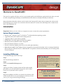
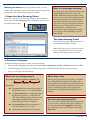
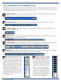
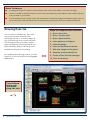
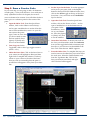
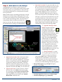
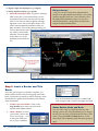
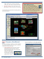
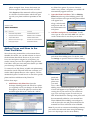
In This Guide: Installing DynaSCAPE 2 Getting Help 3 Getting Acquainted 4 Drawing Exercise: Fence Patio Plant Bed Inserting Figures Labeling Title Block & Border Plant Images Plant Material List Plant Picture Catalogue Printing 8 9 10 11 12 15 16 17 18 20 21 Quick Reference 22 Frequently Asked Questions 26 The Learning Centre 27 DynaSCAPE Products 28 Quick Start Welcome to DynaSCAPE! This Quick Start guide will show you how to get started quickly with DS|Design, perform the basic tasks you need to create a simple design and help you understand how this software can help you build your business. More information about the software can be found in the Training DVD videos that accompany the software and the DS|Design User’s Guide. You can also download an electronic version of the DS|Design User’s Guide from a link on the installation CD. Installation Important: Before you start, check you computer to ensure it meets the system requirements: System Requirements: Windows XP® , Windows Vista® or Windows 7® (32-bit and 64-bit) operating systems 1 gigahertz (GHz) 32-bit (x86) or 64-bit (x64) processor 1 gigabyte (GB) of system memory (RAM) 512MB video card with support for DirectX 9 graphics Minimum screen resolution of 1024 x 768 pixels Microsoft Internet Explorer® 8 or later Internet connection (updates and access to the online plant database) Note: Microsoft Office Suite® 2000 (or later) is required for advanced functionality such as creating material lists (Microsoft Excel® Microsoft Excel®). Adobe Reader® is required for advanced functionality such as creating Plant Picture Catalogues. Installing DS|Design To install DS|Design follow these steps: Step 1: Insert the DS|Design Install CD Step 2: Click on the Install DS|Design option Step 3: Type in your Name, Company Name and the serial number provided to you with the install CD (type the serial number exactly as it is presented with no spaces) Step 4: Begin the installation and allow it to finish. Once finished, click on the DynaSCAPE icon on your desktop to activate your software so you can get started using DS|Design. 2 DynaSCAPE Software Did You Know? The Windows Setup (installation) program automatically creates a program group and appropriate program icons for the application. The installation routine will also create shortcut icons for DS| Design on your Desktop. If you need help... If you experience any difficulties during installation please call us at 1.800.710.1900 Let DynaSCAPE Assist You 1. Online Help 5. The DynaSCAPE User’s Guide Website address: www.dynascape.com If a User's Guide did not come with your software purchase, you can acquire the DS|Design User’s Guide as a hard copy by calling (1-800-710-1900). You can also download an electronic copy for free. Visit our website and click on ‘Support’ for all the online help available to you including Discussion Forums, FAQ’s and downloads. The Discussion Forums are an excellent resource for asking questions and finding answers. 2. Email Email address: [email protected] 3. Phone 1.800.710.1900 Ext 278 (Monday—Friday 9:00am—5:00pm Eastern Standard Time, excluding Canadian Holidays) 4. Training Videos How to download the User’s Guide: From the Help menu in DS|Design you can download an electronic version of the DynaSCAPE User’s Guide by clicking on ‘Online User Manual’. Clicking on this option will open a browser in which you can choose a DynaSCAPE Product Manual. Click on the ‘Open’ option to download and view the User’s Guide . The User’s Guide opens in a separate browser window as a PDF. Once opened, you can use the bookmarks to find the topic you are looking for or use the ‘Search’ option to find help for specific subjects. To save the User’s Guide on your hard drive, click on the ‘Save a Copy’ option. Your software trial includes a DynaSCAPE Training DVD. Take some time to view these detailed instructional videos which show you how to use many more of the DS|Design tools. Learn how to use the various Drawing and Editing tool, the Plant List Editor and much more! Software Activation To use DS|Design you must activate your software license. Activation protects you by ensuring that you have licensed a genuine DynaSCAPE product rather than a counterfeit. Activation protects DynaSCAPE by ensuring that our software is used in accordance with a purchased license. You need an internet connection for activation, so it is important that your computer is connected to the internet when you start DS|Design for the first time. To activate, follow the instructions on the screen when prompted. If your software fails to activate, either because it cannot connect to DynaSCAPE over the Internet or because its use is found not to be permitted, you need to call DynaSCAPE for a Manual Activation Code. DynaSCAPE will not operate until activation has been successfully completed. If you have DS|Design installed on another computer, you can ‘deactivate’ the license on that computer by going to Help > Deactivate... If you need help activating your software call DynaSCAPE Support at 1.800.710.1900 Ext 278. Quick Start 3 Starting DS|Design To start DS|Design in Windows XP or Vista: Double-click on the DS|Design icon on your Desktop. Or if the icon cannot be found: 1. Select the Windows Start button located at the bottom-left of your screen 2. Choose (All) Programs | DynaSCAPE | Design 3. Click on DynaSCAPE Design When DS|Design Runs for the First Time When DS|Design opens for the first time, the drawing screen will have a white background along with some graphics and text (see image below). This drawing contains instructions for opening a new drawing (prototype). Once opened, all new DynaSCAPE prototype will have a black background and have all the available layers, figures and default settings pre-loaded. In the future, when you start DS|Design, the last drawing(s) that you had open will be opened (with a black background). When there are no drawings open in the Drawing Window, many menus and features of the program are not accessible (and will be grayed-out). In order to access all of the features examined in the pages that follow, you need to open a new prototype drawing (see next page). The DynaSCAPE Program Window The DynaSCAPE program window (interface), pictured , contains all the functions of the software. These main components will be referred to throughout this guide: 4 DynaSCAPE Software Before you start: Before you get started with your first design, take a moment to open a blank drawing (prototype) and get familiar with the DS|Design program window: 1: Open the New Drawing Panel Select the “Activate a new drawing” button on the Top Button Bar to open the New Drawing panel to display the list of available prototype drawings. What is a Prototype Drawing? Prototype drawings are blank drawings (also called ‘templates’) that have many preloaded settings that other programs would require you to set up. These settings include, but are not limited to, line weights, layers and dimension styles for many scales and paper sizes. They are designed to make the startup phase of creating a new drawing quick and easy. Choosing one of DynaSCAPE’s many prototypes will allow you to begin work on drafting your plan immediately. The New Drawing Panel The New Drawing panel displays the list of all available prototype drawings. Note: The names given to the various prototypes are designed to help you choose the drawing scale and page size you need. 2: Select a Prototype Complete the following steps to create your first drawing: 1. Select the following prototype from the list: v5.0 : Imp (Landscape) A- 08.5x11—SCALE 1”=8’ and click OK. 2. The drawing page will open with a black background (as with all DynaSCAPE prototype drawings). 3. Now you can begin your first design. What is in a prototype name? About Paper Size V5.0 : Imp (Landscape) A-8.5x11—SCALE 1”=8’ When a prototype drawing first opens, you should see a dashed line that represents the limits of the drawing, based on the paper size you selected. This means that if you print your drawing to that size of paper, your drawing will be at the proper scale (remember to leave appropriate margins for your printer). Orientation Paper Size Scale Description: The paper size shows that this prototype is designed for an 8-1/2” x 11” sheet of paper. The page orientation is ‘Landscape’ (page is displayed lengthwise, or wider then it is tall); other prototypes have ‘Portrait’ orientation (page is displayed like in a book, where the page is narrow and tall). The drawing scale of this prototype is 1” = 8’ (1 inch = 8 feet or 1/8” = 1’-0”). v5.0 indicates the DynaSCAPE version #. Can’t see the drawing limits? If you can’t see the dashed line of the drawing limits on your screen, try turning them on by clicking on the ‘Limit’ button on the Toggle Bar or select the Zoom Drawing Limits control button on the Top Button Bar. Quick Start 5 3: Get Acquainted with the DS|Design Screen Note: Before you begin to draw, it is important to familiarize yourself with the DS|Design program window. This will help you find the tools and functions you are looking for as you create your first drawing. You will be referring to the DS|Design program window pictured on page 4 of this guide: Program Titlebar: the Program Titlebar displays the name of the drawing currently open (if it displays ‘Untitled Drawing…’, the drawing has not been saved to a file) Pull-Down Menus: Many of the settings and controls are accessed through the Pull-down Menus. Visibility Toggles: the Visibility Toggles control the visibility of the Button and Toggle Bars, and the DynaSCAPE Sidebar folder Prompt Line: the Prompt Line displays messages from the program about what type of action or input is required from you to perform a command. Top Button Bar: the Top Button Bar activates the New, Existing, Save and Print Drawing commands, the Copy, Cut and Paste commands, the Delete and Repaint tools and all the Zoom commands. Toggle Bar: the Toggle Bar activates the various Toolboxes, toggles the Constraints and Copy commands, the line Fill and Ends tools, as well as toggle the drawing Limit and Origin. 6 DynaSCAPE Sidebar Folder: Figures Sidebar Folder: this is the heart of the DynaSCAPE program and is the folder which will be displayed most often as you draw. The DynaSCAPE folder is divided into four different areas (in yellow on the screen): Commands (command icons), Labeling (labeling controls), Related Tasks (material list, schedules) and the fourth area called Controls, which changes its name depending on which icon is active beneath it (for example, between Layers/ Styles/Weights, etc.) the Figures Sidebar Folder controls all of the currently active predrafted symbols (called figures) in DynaSCAPE. Figures automatically assume their proper layer and size relative to the drawing scale when they are inserted into a drawing. Although using the default settings assigned to a figure makes drafting quicker, you can change any of the default settings of a figure while you insert it into a drawing (i.e. Scale, Rotation, Width and Height). DynaSCAPE Software Favorites Sidebar Folder: the Favorites Imaging Sidebar Folder: the Imaging Sidebar Folder is home to all the controls related to adding images to your drawing. Images can be photographs of landscapes you have in your collection, images of plants from our online plant encyclopedia, property surveys, logos, etc.: almost any image file format (JPG, BMP) can be brought into DynaSCAPE. Sidebar Folder is a place for all the symbols you have chosen as favorites (accomplished by rightclicking on a library figure in the Figures Sidebar Folder and selecting ‘Add to Favorites’). CLI: the Command Line Interpreter (CLI) is a textbased interface, or communication channel. It provides a textual record of any command you enter in creating a drawing, including information you were required to enter, as well as DynaSCAPE command prompts. All tasks that you perform are recorded by the CLI, even if you use panels, buttons, or the mouse to initiate them. Advanced users can use the CLI to instruct DynaSCAPE to perform tasks by entering commands and data via the keyboard. Understanding the CLI operation simplifies your overall drawing operations, and enables you to use some more advanced DynaSCAPE features. Tables/Modes Settings: the Tables/Modes List displays the lists of Layers, Line Styles, Line Thicknesses, Fonts, Colors and Modes as the buttons for each is selected. 4: Discover the Drawing Tools In order to draw you need tools. DS|Design has conveniently grouped all the basic required drawing tools into two main toolboxes: Drw and Edit. However, for the purpose of this exercise, you can use an even more basic toolbox called Qk St (Quick Start). The Quick Start toolbox contains the nine basic tools that you are going to learn to use while creating your first drawing. To open the Quick Start toolbox, click on the Qk St button: The Quick Start Toolbox Note: If you wish, you can also open the Draw and Edit toolboxes instead and ignore any references to the Quick Start toolbox. Quick Start 7 About Toolboxes To change the shape of a toolbox, click and drag on the corner of the toolbox you wish to re-shape. To move a toolbox to another location on your screen, click and drag on the title bar of the toolbox and move to any location on your screen. You can find more tools ‘nested’ under each tool that has a small, blue triangle in the bottom right corner. To access these tools, click and hold on the tool while moving your mouse down to reveal the nested tools. Drawing Exercise Now it is time to start drawing. The easiest way to learn the basic elements of the DS|Design software, is to create a simple design. The following set of exercises will walk you through the steps of creating a simple patio with plantings. The design will be complete with labels, pictures and end up with a material list and a plant care package. Steps to complete this exercise: 1. Draw a fence line 2. Draw a circular patio 3. Draw a plant bed line 4. Insert patterns and figures 5. Label the design 6. Insert a title block and border 7. Add color images of the plants 8. Generate a plant material list By completing the following exercise, you will learn how to use each of the tools in the Quick Start toolbox: Your finished design will look something like this: 8 DynaSCAPE Software 9. Create a Plant Picture Catalogue 10. Print the drawing Step 1. Draw a Fence Line About Layers The first step in creating your design is to draw a base plan. In this case the base plan consists of a 30’ section of fence: Layers are an important aspect of CAD drawings. Layers control the screen color, line style and line thickness of elements placed in your drawing. Layers can be turned ‘on’ or ‘off’ to isolate specific aspects of your drawing. 1. 2. 3. Set the Proper Layer: Before you draw your line, you must first set the proper layer for that line to be on. This will set the appropriate line weight and line type for the object you are drawing. To set the layer for your fence, click on the Layers button in the DynaSCAPE Sidebar Folder. Next, click on the Select toggle at the top of the layer list and click on the Fence_A layer in the list. Set the drawing Constraints: In order to have your line ‘snap’ to a vertical or horizontal position on your drawing, you must set the constraints. To do this, click on the Constraints button on the Toggle Bar and select Ortho from the list that appears. Open the Line drawing tool: To draw your line click on the ‘Draw a Line’ tool from the Quick Start toolbox. A modifier panel will appear. About Constraints To temporarily turn your constraints on while performing a command in DS|Design, hold the [Ctrl] + [Shift] keys on your keyboard. 4. Set the Line Length: In the modifier panel, type in 30’ for the length of our fence section. You do not need to set the Angle since the constraints were set to Ortho. 5. Insert your fence into the drawing: Next, click on the drawing page for first point of the line. For your drawing click on the left side of centre (see diagram below). Next, move your mouse to the right and the 30’ line will snap horizontal on the drawing. Click to place the second point of the line. To end the process, right-click anywhere on the drawing page. The Importance of Saving Your Work It is important to save your drawing after each step. If you have a power failure or a computer crash, you may lose any unsaved work. DS|Design has a drawing recovery option, but it is not wise to work for long periods of time without saving your work. Quick Start 9 Step 2. Draw a Circular Patio 4. In your next step you are going to add a 10’ diameter circular patio, 3’ away from the fence. You could just as easily eyeball the location of the patio, but in most cases it is better to be accurate. You will offset the fence line to give us a reference point for the centre of the patio: Set the Layer for the Patio: To set the appropriate layer for your patio, click on the Layers button in the DynaSCAPE Sidebar Folder. Next, click on the Select toggle at the top of the layer list (white = ‘On’) and click on the Walk/Patio layer in the list. 5. Open the Circle Tool: From the Quick Start toolbox, click on the ‘Draw a Circle…’ tool to open a modifier box to set the dimensions of your patio. In the modifier box, enter 10’ as your Diameter. Press the [Space] or [Enter] only once to set the number. 6. Insert the Circle Patio: To insert your circle on the line you offset earlier, make sure Inference is on (on the toggle bar beside constraints) and then move your mouse over the middle of the line. Click when the text ‘MidPt’ appears. 7. Erase the Offset Line: To complete this step you need to remove the offset line you used to insert the circle onto. Select the ‘Delete Entities’ tool from the Top Button Bar. Click on the line you offset (it turns blue) and rightclick. The line will disappear. 1. 10 Open the Offset Tool: From the Quick Start toolbox, click on the ‘Offset or move line(s)…’ tool to open a modifier box to set the offset distance. In the modifier box, enter 8’ as your distance (since this prototype’s units are set to feet, you do not need to enter the foot symbol). Press [Space] or [Enter] only once to set the number. 2. Turn Copy on: On the Toggle Bar, click on the Copy toggle to turn it (white = ‘On’) 3. Offset the Fence Line: Click on the fence line on your screen (it will highlight in blue) and then right-click to complete the selection. Click anywhere on your screen on the side of the fence that you wish to eventually place the patio. A second line will appear 8’ away from your fence line. DynaSCAPE Software Step 3. Draw a Plant Bed Line 5. Drawing your plant bed line will give you the chance to use the curved polyline tools. But first you are going to offset the fence line again and use that line as a starting point and a reference for your plant bed line. Reference lines are not always necessary, but can be helpful: Turn the Constraints off: On the Toggle Bar click on the Constraints button and select None from the pull-down list. 6. Open the Polyline Tool: In the Quick Start toolbox, click on the ‘Draw a straight or curved Polyline…‘ tool to open a modifier box. In the modifier box select the Smooth polyline and Auto bulge options. 7. Insert the Bed Line: To insert your bed line polyline, make sure Inference is on and move your mouse over the line near the end on the left hand side. Click when the text ‘End’ appears. Move your mouse down and to the right and click to make a second point (see diagram below). Move your mouse right and click to make a third point. Continue moving your mouse across to the far right end of your offset line and click when the text ‘End’ appears. Right-click to finish. 8. Erase the Offset Line: To complete this step you need to remove the offset line you used to insert the plant bed line onto. Select the ‘Delete Entities’ tool from the Top Button Bar. Click on the line you offset (it turns blue) and right-click. The line will disappear. 1. Open the Offset Tool: From the Quick Start toolbox, click on the ‘Offset or moves line(s)…’ tool to open a modifier box to set the offset distance. In the modifier box, enter 5’ as your distance . Press [Spacebar] or [Enter] only once to set the number. 2. Turn Copy on: On the Toggle Bar, click on the Copy toggle to turn it (white = ‘On’) 3. Offset the Fence Line: Click on the fence line on your screen (it will highlight in blue) and then right-click to complete the selection. Click anywhere on your screen on the same side of the fence as the patio. A second line will appear 5’ away from your fence line. 4. Set the Layer for the Plant Bed: As usual, the first step before drawing an object in DynaSCAPE is to set the layer for your plant bed line. Click on the Plantbed layer in the Layer list in the DynaSCAPE Sidebar Folder. Quick Start 11 9. Trim the Plant Bed Line: The last step to finish the plant bed line is to trim the section of line that overlaps the patio. Click on the ‘Trim (clip) lines…’ tool in the Quick Start toolbox. Next click on the section of the plant bed line that overlaps the patio. Right-click and the section will be re- Step 4. Insert Patterns and Figures Now it is time to insert your pattern into your patio and place symbols of your rocks, trees and shrubs (figures): 1. Set the Layer for the Pattern: Click on the Patten_A layer in the Layer list in the DynaSCAPE Sidebar Folder. 2. Open the Hatch Pattern Tool: From the Quick Start toolbox, click on the ‘Insert a hatch pattern…’ tool to open a modifier box (the one with the blue dot). Although you can choose any pattern and adjust the scale and rotation, you will use the default pattern: ‘TUMBLED_A’ with the default scale of 0.325. 3. Insert a Pattern into the Patio: To insert the pattern, click anywhere inside the circle patio and right-click. The pattern will fill the circle completely. Next you will learn how to insert the shrub, 12 DynaSCAPE Software tree and rock symbols: 4. Open the Figures Sidebar Folder: All the figures provided with DynaSCAPE can be found by clicking on the Figures sidebar folder. By clicking on the arrow beside the name that appears at the top of the list of figures , you can select any Figure Library from the list to find the symbols you wish to use. All the figures are drawn to the appropriate scale, allowing you to insert them directly into your drawing. 5. Choose a Symbol to Insert: For the purpose of this exercise you are going to use specific symbols to create your design. Use the scroll bar to sort through all the symbols in each library. 6. How to Insert a Symbol: Click on the figure you wish to insert and move your mouse over the drawing page. A ghost image of the symbol will be attached to your crosshairs. Click on the location you wish to place your symbol and right-click to finish insertion. The ghost image will remain attached to your crosshairs, allowing you to insert the symbol as many times as you wish. 7. How to Rotate a Symbol: If you wish to rotate the symbol during insertion, move your mouse away from the insertion point and pull in the direction you wish to rotate the symbol, click once more and then right-click to end. 8. Insert Symbol #1: The first symbol to insert is the conifer. In the TREES-6 library, scroll down to find and click on the SPEC_CONIFER symbol. In- sert it into the drawing as shown in Figure 1. You do not need to rotate this figure. 9. Insert Symbol #2: The second symbol to insert is the ornamental grasses. In the GRASSES-6 library, scroll Figure 2 down to find and click on the 3FT_SPEC_GRASS symbol and insert three times as shown in Figure 2. 10. Insert Symbol #3: The third symbol to insert is the daylily. Figure 3 Need to move a Symbol? There is more than one way to move a symbol in DynaSCAPE. The easiest way is by using the ‘Move or Copy Objects…’ tool in the Quick Start toolbox. Click on the tool and then click on the object you wish to move. Rightclick to end the selection and click on the middle of the object . This will create an insertion point and the object will be attached to your crosshairs. Click on a new location for the object. If the Copy toggle is on, a copy of the object will be created . Figure 1 Quick Start 13 11. Insert Symbol #4: The fourth symbol to insert is the rock. In the ROCKS-6 library, scroll down to find and click on the 36IN_NATURAL symbol and insert it as shown in Figure 4. Since this one will need to be rotated, follow the instructions in Step 7. Figure 4 12. Insert Symbol #5: The fifth figure to insert is the spreading evergreen. In the SHRUBS-A-6 library, scroll down to find and click on the 3FT8_SPR_EVG symbol and insert four times as shown in Figure 5. 13. Insert Symbol # 6: The last symbol to insert in this exercise is the flowering shrub. In the SHRUBS-A-6-library, scroll down to find and click on the 3FT6_FL_SHRUB symbol and insert three times as shown in Figure 6. Figure 6 14. Group (Cluster) the Symbols: Once you are satisfied with location of your symbols, you are ready to cluster them into tidy groups. In the DynaSCAPE Sidebar Folder, click on the ‘Blend and Group Figures’ tool and select Erase all inner segments in the modifier box that appears (it may be on already) . Click on the three flowering shrubs and then right-click. The overlapping segments of the symbols will be removed as a result. Repeat the same process for each group of identical plants. Figure 5 Did you Know... ...that you can right click on a symbol in the figures list and select ‘Toggle figure view’ to get a close-up view? About Clustering Symbols Cluster Results You will notice that some plant symbols like the ornamental grass and the daylily will not change visually after clustering. However, the benefit of clustering these types of symbols will become apparent when using the AutoCount feature during Softscape Labeling. 14 DynaSCAPE Software Step 5. Add Labels to the Design Adding labels to the design is quick and easy in DynaSCAPE. First you are going to label using a plain text leader where you type in the text. Then you will use Softscape labels that you will generate a material list or quote from. Note: Another option for labeling hardscape or design elements is to use the Design Label panel. This is not covered in this Guide but you can learn about it in the User’s Guide and Training Videos. The advantage of using Design Labels is efficiency and the fact that you can also add units and prices that will be included when creating your material lists. 3. Insert the Text Label: To place the label on your plan, you must first set the layer you wish to put the text on and you must set the constraints so your leader lines are snapped straight on the drawing. For plain text labels you will set your layer to Text_Labels and your constraints to Polar. To insert the label, first click on the location for the first point of your leader (the arrow) and move your mouse in the direction you wish to pull the leader line. Click where you wish to put an elbow in the leader line and pull and click where you wish to add an extension to the leader. Right-click to finish the label. Next you will label your plants with Softscape labels. 4. Open the Softscape Label Panel: Using the Softscape Labeling Panel to label your plants will enable you to generate a material list and Plant Picture Catalogue. Open the softscape labeling panel by clicking on the ‘Place a softscape label’ tool in the DynaSCAPE sidebar folder. For this exercise you are going to search for your plant names on the On-Line Plant Database. This gives you access to over 9,000 plant records from across North America. To do this click on the pull-down arrow beside the Find button and select the ‘at dynascape.com’ option. 1. 2. Open the Text Leader Tool: In the Quick Start Toolbox click on the ‘Insert text attached to a leader’ tool to open the modifier box. The modifier box contains three tabs: The Attributes tab contains the settings for the leader, while the Text tab contains the settings for the text. Both are set correctly by default and do not need to be adjusted. In the last tab, Edit, you can insert text. Type in your Text: To enter your text, click on the white box in the Edit tab and start typing. For your patio, type PAVING STONE PATIO and click Apply. After adding the label to the plan, replace the text in the box with MOSS BOULDER to label the rock. 5. Search for Plants: To search for any plant type the name in the search box and press [Enter] or click on the Find button. The results will be displayed in the panel below. If your result comes up empty, you may need to shorten the search name or check your spelling. For this exercise you will be labeling with specific plants: Hoopsii Blue Spruce (type hoopsii and press [Enter] or click Find) Autumn Light Silver Grass (type autumn light) Annabelle Hydrangea (type annabelle) Quick Start 15 Calgary Carpet Savin Juniper (type calgary) Chicago Apache Daylily (type apache) 6. Insert the Softscape Labels: To place a softscape label on the plan, you must first find your desired plant name in the search results list and click on it to select it. Selected plants will highlight blue. Next, click on the Go>> button. The panel will automatically minimize while you place the label. Click on the plant grouping you wish to label and the quantity will be counted automatically. Insert the label in the same way as the leadered text inserted earlier. Did you know... ...that you can click on the Show Selected Plant Details to see plant details and a link to ’view plant profile at DynaSCAPE.com’? This will take you to the Online Plant Database where you can view cultural information , design ideas and full-color images of that particular plant. Step 6. Insert a Border and Title Block Now that your design is essentially complete, you need to add a border to the drawing page and a title block. The border is basically a drawn rectangle, while the title block is pulled from the library and contains some automation: 1. 2. 16 Set the Layer for a Border: Click on the Page_Border layer in the Layer list in the DynaSCAPE Sidebar Folder. Draw a Border: To insert your border, click on the ‘Draw a rectangle…’ tool in the Quick Start tool box to open a modifier DynaSCAPE Software box. In the modifier box type in a width of 82’ and a height of 62’. Click on the upper left-hand About Delete, Undo and Redo You can undo a step you performed at any time during a process by using the [Delete] key as long as the tool you are using to perform the function is still active. Using the Undo and Redo buttons, on the other hand, will completely undo the entire group of steps. corner of the drawing page, approximately 3/8” from the drawing limits. Click on the lower right hand corner of drawing page to complete the insertion. 3. Find a Title Block: DynaSCAPE contains two figure libraries with title blocks for most common drawing scales and sheet sizes. Click on the Figures sidebar folder and look in the T-BLOCK HORIZ-6 library for the title block named 8.5X11_1to8. 4. Insert the Title Block: Select the 8.5X11_1to8 title block and insert it in the bottom right hand corner of your drawing page, just inside your border. Click to place it and right-click to finish. 5. Insert Title Block Information: To fill out all the needed information in the title block, click on the ‘Title text editor’ button in the DynaSCAPE sidebar fold- er. The Titleblock Editor panel will open. Fill in the title by selecting the tag from the Property Tag list (e.g. Client_Name), then clicking in the Property Text field and entering your text. After the text is entered for an item, select another category (or Tag) on the left, then click into the Property Text field again and type in the data for that category. You will see the text appear automatically in the title block on your drawing after you select the next tag. (Only the tags marked with a ‘T’ will be shown in the titleblock). When you are finished, click OK. Titleblock information can be changed at any time by clicking on the ‘Title text editor’ button. Step 7. Add Plant Images Adding full color images to your design is quick and easy in DynaSCAPE. There are two tools that can be used to search for plant images that are found in the Imaging sidebar folder. The first requires you to type the plant name in yourself. The tool you will use in this exercise only requires you to click on a plant label. 1. Search for a Plant Image: In the Imaging sidebar folder, click on the ‘Search for a plant image based on a Softscape label' tool. Next, click on one of the softscape labels in your design and then rightclick. The Online Plant Database Search panel will appear, showing the image that is available for that particular plant. 2. Insert the Image: To insert the image, click on the Insert Image button. The Image Search panel will disappear. On the drawing page, click where you wish to place the top-left corner. Next, move your mouse diagonally across the screen (down and to the right) and click where you want the bottom-right corner. This will determine the size of the window in which the image will be placed. DynaSCAPE will then place the image at the location you specified, with the text beneath the image. If you are not Quick Start 17 happy with the size or location of the image, click on the ‘Undo’ button and repeat the steps. 3. Insert More Images: Follow these steps for each plant image you wish to include in your drawing. Your finished drawing should look something like the one illustrated below: Step 8. Generate a Plant Material List Now that your design is complete, it is time to produce an accurate material list from your design. To generate a material list, follow these steps: 1. 18 Export a Material List: Click on the ‘Export a material list from this drawing’ tool in the DynaSCAPE sidebar folder. This will open the Export Plant Material List wizard. You may change the name that is automatically inserted in the Client Name text box. You can DynaSCAPE Software About Adding Images You can also add your own images (photos) by using the Insert a Raster Image… tool. Clicking on this tool will enable you to locate an image file on your computer that you wish to insert (JPG or BMP). You can also use this tool to insert a scanned lot plan that can be traced for your next design's base plan. choose the columns you wish to have appear in the list as well as how you would like to see the plants arranged. Next, choose the format you wish to export to: Microsoft Word® or Excel®. Click Export and the materials will be exported to a Word or Excel document which will open up with your plants and their quantities in the list. my Plant List’ option. If you now choose to search ‘in my Plants’, the plants you added will automatically appear in the list. 2. Open the Plant List Editor: Click on Edit My Plant List at the top of the labeling panel. The Plant List Editor will open and the plants added will appear here along with a thumbnail picture and cultural information for each plant. 3. Add Sizes and prices to Your Plants: To add sizes, type in a size and click Add. You can also create a master list of sizes that you can then Adding Prices and Sizes to the Plant List Editor Since the ensuing material list is a document that is editable, this means you can add columns or sizes to the document afterwards. However, if you wish to have sizes and prices assigned to your plants, you need to create your own list of plants using the Plant List Editor. Add your sizes and prices before you label your drawings with these plants. To create a list of ‘My Plants’ to label with (eliminating the need to search at DynaSCAPE.com each time you need to label a plant) there are a few options. The recommended option covered here is to search for specific plants and then add them to My Plant List. Follow these steps: 1. Add Plants to My Plant List: Open the Softscape Labeling panel and search for a plant you regularly use in your designs. In the results that appear, click on the plant you wish to add and then right-click on it. Choose the ‘Add to pick from when adding sizes. To do this, click on Settings to open the Plant List Editor Settings panel and add all the plant sizes you need. Now, when adding sizes to individual plants, the master list of sizes will appear as you begin to type, narrowing down your search as you continue to type. You can assign a price to each size you add. When labeled on a design, these prices will be automatically added to your material lists. Plants labeled before adding sizes and prices will not have the size and price included in the material list. These will need to be re-labeled. Note: If you wish to create more detailed quotations, you can do this and much more using DS|Manage (see www.dynascape.com for more details). Quick Start 19 9. Create a Plant Picture Catalogue DynaSCAPE also has the ability to quickly generate a Plant Picture Catalogue, complete with color photos. It requires that your computer be connected to the internet. Your drawing must be labeled with plants using the Softscape Labeling Panel in order to use this feature. Follow these steps: 1. Export Plant Picture Catalogue: Click on the File menu and select the Export > Plant Picture Catalogue (PDF) option. This will open the Ex- About Matching Images If you have a plant that is not matched to the Online Plant Database you can only do that through the Plant List Editor. Open the Plant List Editor, find the plant that is not matched and click on Match Plant under ‘No Image Available’. DynaSCAPE will find an exact match or any close matches for you to choose from. 5. Click Next. Edit the title (if needed) and select the label options you would like to have shown beneath each plant picture. 6. Click Finish. You will be prompted to give the PDF file a name and a location to save it. 7. Click Save and DynaSCAPE will download the pictures from the Online Plant Database and then open the finished Plant Picture Catalogue as a PDF (you need to have Adobe Reader installed). You can print it out or email it to your clients port Plant Catalogue wizard. The list of plants will be displayed on the left. 2. 20 Click on a plant in the list and a thumbnail of the plant will be displayed on the right side of the panel. 3. You can use your own photo if you wish by clicking on Custom Picture and browsing your computer to the picture you wish to use. 4. Deselect any plants you do not want to show in the Plant Picture Catalogue. DynaSCAPE Software 10. Print the Drawing The very last step in the drawing process is to print your design. It is preferred to use a color printer to print the color images you have added to your drawing. Since your drawing was completed on an 8-1/2”x 11” you do not need a special printer to do this. 1. Open the Print Drawing Window: On the Top Button Bar, select the Print the active drawing button. In the Print Drawing window that appears, first click on the Printer setup… button to open the printer settings window. 2. Set the Printer Settings: In the printer settings window, first select the printer you wish to print to. Next, select the paper size (for this drawing choose Letter) and the orientation (choose Landscape). Next, click on the Properties button and set your print quality to Normal and your color to Color. Click Ok. 3. Choose the Color Settings: In the Print Drawing window, click on the Color tab and make sure it is set to Print using a single color. 4. About Printing and Color When using these settings, the CAD portion of your drawing will print in B&W and your settings will over-ride the printer Color settings. Since plant images are not embedded into the drawing, the images will still print in color as determined by the printer settings. 5. Choose the Print Scale: In the Print Drawing window, click on the Scale tab and make sure the scale is set to Print using the active drawing scale. 6. Set the Drawing Preview: In order to see if the drawing will print correctly, click on the Preview printable area option at the bottom of the Print Drawing window. When this setting is on you will see a red box on the drawing window, just inside your drawing limits (zoom out if you cannot see the drawing limits). If part of your drawing appears to be outside the red box, it will get cut off during printing and you may need to exit the printing process and adjust your drawing. If it appears correct, click Print. Choose the Print Bounds: In the Print Drawing window, click on the Bounds tab and make sure the bounds set to Print the area defined by the drawing limits. Note: If your drawing does not print as expected, follow these steps again to ensure nothing was missed. Congratulations! You have just completed your first DynaSCAPE design. Quick Start 21 Keyboard Short Cuts CTRL + A Select everything on your screen CTRL + C Copy to the clipboard CTRL + X Cut to the clipboard CTRL + V Paste from the clipboard CTRL + H Opens the Drawing Page panel CTRL + K Opens the Overview Panel SHIFT Turns on your Inference Settings temporarily until SHIFT is released. CTRL + SHIFT Temporarily turns on the Constraints to ‘Polar’. CTRL + Left Click Holding CTRL while left-clicking on an object opens up an Entity Attributes panel. Keyboard Commands ( t o use: type in command followed by [Space] or [Enter key] ) Z Activates on the Zoom the Drawing using a Window tool ZZ Activates the Zoom to the Drawing Limits tool ZD Activates the Zoom to the Drawing Extents tool PAN Activates the Scroll (pan) drawing tool CO Activates the Move or Copy tool with the ‘Copy’ toggle turned on CF Activates the Move or Copy tool with the ‘Copy’ toggle turned off D Activates the Delete Entity tool (erase) L Activates the Insert Line tool LL Activates the Insert Line tool and allows you to enter a length C Activates the Circle tool CC Activates the Circle tool and allows you to enter a radius P Activates the Polyline tool PC Activates the Polyline tool with Smooth polyline selected and Constraints turned off PCA Activates the Polyline tool with Smooth polyline selected, Constraints turned off and the Define Angle option ready RFO Allows you to revise the Fill off of selected lines or curves RFN Allows you to revise the Fill on of selected lines or curves R Repaints the drawing page ROB Activates the Revise Entity tool and sets the output color to black for selected items 22 DynaSCAPE Software The Top Button Bar Zoom Tools Start a New Drawing Zoom Drawing Limits Open a Existing Drawing Zoom Previous Save the Current Drawing Zoom Drawing Extents Print the Current Drawing Zoom In/Zoom Out Undo/Redo Scroll (Pan) Cut to the Clipboard Zoom to a Window Toggle Bar Buttons Copy to the Clipboard Paste from the Clipboard Inference—for snapping accurately to objects Delete or Erase Tool Constraints—guides for drawing lines and moving Copy—position determines if objects move or copy Repaint the screen Mouse Wheel Zoom & Pan Mouse Wheel Zoom—to zoom in and out of your drawing using the mouse wheel, press the [Shift] key while rotating the mouse wheel forward or backward. Mouse Wheel Pan—to pan using the mouse wheel, press the [Shift] key and push the mouse wheel down while moving the cursor around on the drawing page. DynaSCAPE Sidebar Folder Group (cluster) Figures—Groups tree and shrub figures together Softscape Label— For labeling plants and accessing the Plant List Editor Group Labels—Group labels into work areas or phases (for integration with DS|Manage) Title Block Editor—Use with automated titleblocks Design Label—For labeling design elements and for takeoffs Create Material List— Creates a Word or Excel list from the labels Quick Text Tool—To Text Leader Tool— insert text using prompt line For inserting text attached to a leader. Plant Schedule— Inserts a plant list based on labels Quick Start 23 Draw Tools Building Outline Tool—For drawing walls, windows and doors (V4.3) Line Tool—For drawing lines Fillet Tool—For rounding corners. Polygon Tool—For drawing N-sided polygons Rectangle Tool—For drawing squares and rectangles Circle Tool—For drawing circles Pattern Tool - for inserting basic patterns Hatch Tool—For inserting landscape patterns Text Tool—For inserting text into the drawing Polyline Tool—For drawing straight or curved lines. Text Leader Tool—For inserting text attached to a leader. Arc Tool—For inserting arcs where a radius is specified 24 DynaSCAPE Software Edit Tools Move/Copy Tool— Depends on position of Copy toggle Mirror Tool—Depends on position of Copy toggle Offset/Move Tool— Depends on position of Copy toggle Break Tool—Break a line at or between intersections of other lines (no scissors) Scale Tool— Depends on position of Copy toggle Generate Points Tool—For placing points along a line Trim Tool—Clip to the intersection of another line (scissors) Offset Figures Tool— For offsetting figures along an existing line Trim /Extend Tool— Clip or extend to the intersection of another line (scissors) Rotate around an Origin - Depends on position of Copy toggle Trim /Extend Tool— Clip or extend a line to a location (scissors) Rotate by Angle - For rotating by a set angle and any number of copies Trim /Extend Tool— Clip or extend 2 lines to a corner (scissors) Measure Area Tool— Measure by creating a polygon Join Tool— Joins contiguous lines & arcs to form a polyline Measure Area Tool — Measure by selecting a contained location Align Tool—Aligns objects square on your page or to other objects Measure Length Tool—Measure length by selecting 2 points Explode Tool— Breaks down polylines, hatches and figures Measure Length Tool—Measure length or circumference DynaSCAPE Sidebar Folder (continued) Layer List—Choose or revise your object layer Line Width List— Choose or revise width Color List—Choose or revise your screen colors Line Style List—Choose or revise your line style Font List—Choose or revise your fonts Modes List—Turns groups of layers on/off Imaging Sidebar Folder Figures Sidebar Folder The Figures sidebar folder displays the list of available Figure Libraries and their corresponding figures. Click on the arrow beside the library name to find another library from the list that appears. Image Search— Find a plant image at DynaSCAPE.com To insert a figure into a drawing: Image Search—Find a plant image by clicking on a label Step 1: Left-click and release on a figure Step 2: Move your mouse to your drawing page and left-click on your selected location. Right-click to finish To add a figure to the Favorites tab: Insert Raster —Insert lot plan or photo (.jpg) Move Raster — Move image on drawing page Step 1: Right-click on a figure in a library Step 2: Left-click on the ‘Add to favorites’ option Re-size Raster — Resize image on drawing Advanced Tools Define a New Figure —For adding a figure to the libraries Edit Text Tool — For editing existing text Define a New Library —For adding a new figure library Insert Arc Tool—For drawing arcs Cartesian Array Tool— For offsetting figures vert. or hor. Offset Figures Tool— For offsetting figures Edit Text Leader Tool—For editing leader text and the text leader/arrow Insert Titleblock Text Node—For creating text nodes for automated titleblocks. Edit Dimensions Tool—For editing dimensions and dimension lines Cumulative Linear Measure Tool—For taking cumulative linear measurements Revise Entity Attributes Tool —For editing entity settings Cumulative Area Measure Tool—For cumulative area measurements Raster List —Display list of raster images Dimension Tools Linear Dimension — Insert dim. at any angle Horizontal Dimension — Insert horizontal dim. Vertical Dimension — Insert vertical dim. Horizontal Baseline Dimension — Multi dim. Vertical Baseline Dimension — Multi dim. Radius Dimension — Insert radius dimensions Quick Start 25 Common Questions about DynaSCAPE: 1. Can I change my scale or sheet after I start my design? Yes you can. To change sheet size or scale go to Environment > Drawing Page… and change the page settings there. When changing scale, the existing and new geometry will adjust to the new scale. 2. My text is too big or too small—how can I change the settings? To change the default text settings for the current drawing, you need to do it in two places. For text without a leader, go to Entity > Text… For text with a leader go to Entity > Dimension… and select Text… in the Global Dimension Settings panel. This will not change already existing text on a drawing. 3. Can I bring a lot plan into DS|Design? Yes, you can bring a lot plan into DynaSCAPE after it has been scanned as an image file. These images are called ‘rasters’ in DynaSCAPE and they can be traced and then deleted to save time preparing a base plan. JPG images are recommended and smaller file sizes (under 2MB are best). 4. Can I open an AutoCAD drawing in DS|Design? Yes. DS|Design’s AutoCAD® Import feature allows you to bring a DWG or DXF file into Design to use as a base plan or drawing. AutoCAD®’s geometry is converted to DynaSCAPE geometry and can be deleted or edited using DynaSCAPE’s drawing or editing tools. Click on File > Import > AutoCAD® dwg/dxf… to import them into a drawing. DynaSCAPE can import files from AutoCAD® versions 12 up to 21 (up to AutoCAD® 2008). For detailed instructions please see Chapter 17 in the DS|Design User’s Guide. 5. I don’t have a large printer—how do I send a drawing to a Print Shop? Since your print shop will not likely have a copy of DynaSCAPE, you cannot send them a DynaSCAPE drawing file (DPD). Instead, you can send them an Adobe PDF file of the drawing. It is recommended that you send an Adobe PDF, since this is the type that provides the best quality output and one that most print shops prefer. 6. Can I use my own pictures in my design? Yes, you can use any picture you like as long as it is a JPEG or Bitmap. Keep original image sizes small, especially if you plan to use a lot of them on the same design. You can print the design with black an white lines ,while the pictures will print in full color. Keep image files small and do not use PNG or TIF files. 7. Can I copy parts of my design into another drawing? You can copy and paste any part of a drawing except an image (raster). You can also save details and custom figures to the libraries to reuse them at any time. Note: If you have any other questions that may be relevant for other DynaSCAPE users, feel free to add them to the DynaSCAPE Discussion Forums. 26 DynaSCAPE Software Want to Learn More? To learn more and become efficient with DynaSCAPE, we encourage you to consider one of the many options available to you: 1. Instructor-Led Classroom Training DynaSCAPE Software offers instructor-led training courses for beginner and advanced level users of DS|Design within North America. Increase your productivity and workflow efficiencies through hands-on learning. Check our website to find course schedules, locations, outlines and pricing (currently by request only). DS|Design Introductory Training (3-Day course) - This is an introductory course and is designed for those who have some or no experience with DS|Design. Here you will learn the basics in order to get you up and running quickly. DS|Design Advanced Training (1-Day Course) - This is an advanced course and is intended for anyone who is comfortable with the basic operation of DS|Design and wishes to improve his or her drafting speed and the presentation quality of his or her drawings. 2. Instructor-Led Web-Based Training These are on-line training sessions where you connect with an instructor through the web and via telephone. From the comfort of your home or office you can follow an instructor through a specific topic and ask questions. Check our website to see scheduled times and pricing. Introduction to DS|Design (10.5 hours) - this course is divided into three sessions of 3-1/2 hours each. This is also an introductory course to be taken in place of the 3-Day class and is designed for those who have little or no experience with Design. Here you will learn the basics in order to get you up and running quickly. DS|Design Intermediate Training (3.5hrs) - This course is for users who have a good understanding of the basic concepts of DS|Design and wish to get to the next level of proficiency. DS|Design Advanced Drawing & Editing (3.5hrs) - This course is for users who are comfortable with the basic and intermediate topics and want to upgrade their drawing and editing skills. DS|Design Advanced Customizing (3.5hrs) - This course is for the user who wishes to customize and personalize DS|Design to make it fit their workflow and style. Introduction to DynaSCAPE Color (1.0 hr) - learn how to use all the coloring tools, techniques and best practices. 3. Other Training Options On-site Training - contact DynaSCAPE to inquire about creating a custom training session at your office with a qualified DynaSCAPE instructor. Custom Web Training - contact DynaSCAPE to inquire about creating a custom on-line training session specific to your or your company’s needs. Training Information To register, please contact us by: Email: [email protected] Phone: 1.800.710.1900 You can also register online at: www.dynascape.com/learningcentre Quick Start 27 Thank you for choosing a DynaSCAPE software product. You have joined thousands of businesses that rely on DynaSCAPE every day to help them run their business in a professional way. We are committed to helping you spend less time with old-fashioned and inefficient systems and spend more time on your business. Products: This CAD software is perfect for the Landscape Designer or the Design/Build Contractor looking for professional software . It includes a full-featured 2-D CAD functionality with a built in customizable plant list that connects to DynaSCAPE’s Online Plant Database. Design also integrates with DS|Manage360, a powerful estimating and business management tool. Check our website for more details. This is the ultimate presentation tool that adds full color to your DS|Design drawings. DS|Color is a separate module that provides all the tools needed to turn a DynaSCAPE drawing into a colored masterpiece that looks like it was colored by hand. Check our website for more details. DynaSCAPE Sketch3D helps you transform your 2D DynaSCAPE or AutoCAD drawings into full 3D models. It’s a convenient, easy to use add-on for Google SketchUp, the worlds most popular and readily available 3D modeling tool. DS|Sketch3D expands Google SketchUp’s capabilities by adding landscape-specific tools and content. Introduce your business to the most powerful estimating, business management and job costing software for the green industry. Built specifically for the landscape professional, DS|Manage360 consolidates your entire business into one software package. This is a web-based solution for your convenience. Check our website for more details. The leading source of horticultural information software for the Green Industry since 1991. Horticopia Professional software contains detailed cultural data and full color images for thousands of plants. It allows you to view plant pictures and information for a single plant or a group of plants and find, organize, and manage plant information and lists. Check our website for more details. For our full line of products visit our website at www.dynascape.com To speak to a DynaSCAPE Sales Representative call us 28 DynaSCAPE Software 1.800.710.1900 Version: 6.0 Date: 11/25/2011