1
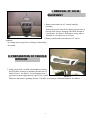
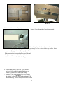
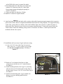
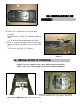
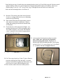
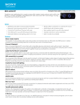
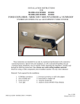
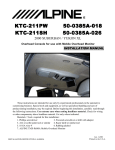
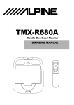
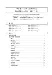
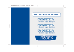
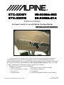
KTC-222GY
KTC-222TN
50-0388A-002
50-0388A-014
FORD EXCURSION
Overhead Console for use with Mobile Overhead Monitor
INSTALLATION MANUAL
These instructions are intended for use only by experienced professionals in the automotive
customizing business. Special tools and equipment, as well as specialized handling and care of
product during installation, may be required. Before beginning this installation, carefully read through
the following instructions. Use extreme care when cutting headliner material. Check for wiring
or other componentry above headliner material. Cut only where indicated.
Materials / Tools required for this installation:
1. Phillips screwdriver
2. Powered screwdriver or drill with adapter
3. Awl or scribe point tool or similar
4. Razor knife or similar tool
5. 18 GA wire 4'
6. 1/8" Drill Bit
7. Rubbing alcohol
8. ALPINE TMX-R680A Mobile Overhead Monitor
INSTALLATION INSTRUCTION # 44-0088A
Dec. 31,2000
Printed in the U.S.A.
MATERIALS PROVIDED FOR
INSTALLATION:
ITEM
1
2
3
4
5
6
7
8
9
10
11
12
Description
QTY
7
3
1
4
1
1
1
1
1
1
1
SCREW, # 6 x 3/8" PPH
SCREW, #8 X 9/16" PWH
SCREW, #8 X 1" PWH
SCREW, 8-32 X 1 1/2" PPH
CONVOLUTED TUBE, 1/2" I.D. X 3"
VELCRO TAPE, 1" X 6"
TEMPLATE
REAR MOUNTING BRACKET
FRONT MOUNTING BRACKET
A/C BLOCK-OFF COVER
CONSOLE
SWITCH, SPDT
1
2
3
4
Dec. 31, 2000
Printed in the U.S.A.
INSTALLATION INSTRUCTION # 44-0088A
2
I. REMOVAL OF O.E.M.
EQUIPMENT
PHOTO 1
.
1. Remove and retain rear A/C control assembly.
Assembly
housing is secured with (2) two spring clips on front of
housing. Pull down to disengage, then slide forward to
clear bracket. See Photo 1. Disconnect wiring and set
assembly in a safe place for re-use later.
2. Remove and discard center and rear A/C vent in
headliner
by rotating outer ring on louver 90 degrees then pulling
downward.
II. PREPARATION OF VEHICLE
INTERIOR
.
3. Using a razor knife, carefully trim headliner as shown,
this will allow clearance for mounting bracket and A/C
block off cover. See Photo 2. Locate template (item 7
pg2) between dome lights and rear edge of O.E. console.
PHOTO 2
Make sure that arrow is pointing forward. Carefully cut and remove indicated headliner. See Photo2.
3
PHOTO 4
4. Trim insulation at rear of opening as shown in
Photo 3. Leave front side of insulation attached.
5. Use rubbing alcohol to clean sheet metal in area
previously cut. Use a clean cloth to dry surface. Insert
rear mounting bracket (item 8 pg 2) into opening and
position tab 24 1/8” from rear edge of O.E. cut out.
Make sure bracket is centered between roof ribs and
firmly press against roof. See Photo 4. Position
insulation between roof and bracket flange.
6. Remove and retain (1) one O.E. screw in front
pocket of O.E. overhead console. Pull down on
console to gain access to dome light wiring.
7. Construct a 2ft. jumper harness that will connect
PHOTO
the vehicle’s dome light
wires3 to the lights in LCD
monitor housing. Refer to wiring/connections section
4
of the TMX-680A owner’s manual for details.
8. Route dome light wire under brace on console and
connect O.E. connector to the O.E. dome light.
Route jumper harness through pod opening on
console. See Photo 5.
9. Using a test light, test function of lights.
10. Install O.E. console in original manner.
PHOTO 7
11. Install and route all video and audio cables, and any other added component requirements to their respective
places in the vehicle. Refer to component installation instructions for wiring diagrams. The suggested routing
of the video system cable is as follows: Above the headliner from video system to C-pillar. Down the Cpillar to the floor. Route the power lead to an accessory controlled source. Connect the ground lead to the
vehicle chassis. Route the remaining wiring to the VCP location. See Photo 6. Connect per instructions
included with the video system.
12. Install block-off cover (item 10 pg 2) and secure using
(1) one # 8 x 9/16" screw (item 2 pg 2) at rear area
and (1) one # 8 x 1 " Screw (item 3 pg 2) at front
area. Do not overtighten screws. See Photo 7.
PHOTO 5
13. Detach A/C wire harness from brace to allow
connectors to reach the new A/C control location.
See Photo 8.
14. Install mounting bracket (item 9 pg 2 ) by inserting
tabs into slots in O.E. bracket and securing front of
bracket using (2) two # 8 x 9/16" screws (item 2 pg 2)
See Photo 8.
15. Install convoluted tube (item 5 pg 2) around wire
harness to prevent chaffing against bracket.
See Photo 10.
5
PHOTO 6
III. PREPARATION OF
CONSOLE
16. Remove A/C control from rear bezel assembly
previously
removed in step 1. Modify A/C control by drilling (3)
three
1/8" dia. holes in front mounting tabs. See Photo 9.
17. Place A/C control in opening in console (item 11 pg 2).
Make sure control is centered and secure using (5) five
#6
X 3/8" screws (item 1 pg 2). See Photo 9.
PHOTO 10
PHOTO 8
IV. INSTALLATION OF CONSOLE
.
Caution: Use extra support for the console until secured to the vehicle.
Failure to do so may cause damage to console or installed components.
18. Install dome light switch (item 12 pg 2) into opening
on front of console (item 11 pg.2).Raise console into
PHOTO
9 connect A/C control wires.
approximate position
and
6
.
Insert bracket on rear of console into rear mounting bracket (item 8 pg 2) and slide rearward. Position console
against headliner. Make sure console alignment is straight and matches contours in headliner, then secure
console using (2) two # 6 x 3/8" screws (item 1 pg. 2) through the slots in bracket on console into
holes on front mounting bracket. See Photo 10.
19. Release LCD monitor panel from locked position.
Lower to viewing position for access to mounting
location in top of housing.
20. Raise monitor housing into approximate position
and connect all wiring to components. Connect
wiring and cabling per instructions included with
LCD monitor.
21. Check function of all component and lights. See
operating instructions for video operations check.
For further assistance, refer to the TMX-R680A
owner’s manual for the technical support phone
number listed for your area.
22. Insert monitor housing into opening in console.
Note : Make sure wires do not get pinched
between housing and console. Align holes in
housing with clips in mounting bracket. Secure using
(4) four 8-32x 1 1/4" screws (item 4 pg.2). See Photo
11. Caution : Do not overtighten screws.
PHOTO
11 into locked position.
23. Raise LCD monitor
panel
24. Cut Velcro tape (item 6 pg 2) into 2" pieces. Remove
protective backing from tape and apply to remote
controls. Position them against the console door and
press firmly on remote while holding the door.
25. Raise remote control door into locked position.
PHOTO 12
7