1
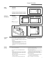
GE Monogram® Installation Instructions Under Cabinet Installation and JX827WN Built-In Kit Microwave Oven Model ZEM200WV Before you begin—Read these instructions completely and carefully. IMPORTANT: Save these instructions for local inspector’s use. IMPORTANT: OBSERVE ALL GOVERNING CODES AND ORDINANCES. NOTE TO INSTALLER: Be sure to leave these instructions with the Consumer. NOTE TO CONSUMER: Keep these instructions with your Use and Care Book for future reference. CAUTION WARNING This appliance must be properly grounded. See “Electrical Supply”, page 6. If you have questions concerning the installation of this product, call the GE Answer Center® Consumer Information Service at 800.626.2000, 24 hours a day, 7 days a week. Proper installation is the responsibility of the installer. Product failure due to improper installation is not covered under the GE Appliance Warranty. See the Use & Care Guide for warranty information. If you received a damaged microwave oven, you should contact your dealer. Contents Design Information Model Available ............................................................................................................................................................... 3 Dimensions and Clearances ........................................................................................................................................... 3 Installation Options ........................................................................................................................................................ 3 Advance Planning ........................................................................................................................................................... 3 Cabinetry ZEM200WV In-Wall Installation .................................................................................................................................... 4 ZEM200WV with Single Oven ........................................................................................................................................ 5 ZEM200WV Under-Cabinet Mounting ......................................................................................................................... 5 Installation Preparation Electrical Supply ............................................................................................................................................................. 6 ZEM200WV In-Wall Installation ................................................................................................................................ 6, 7 ZEM200WV Under-Cabinet Mounting .......................................................................................................................... 7 Installation JX827WN Installation ............................................................................................................................................ 8, 9, 10 Assemble Trim Kit Frame ............................................................................................................................................. 11 Install Trim Kit Frame ................................................................................................................................................... 11 ZEM200WV Under-Cabinet Mounting ........................................................................................................................ 12 To Drill from Inside ................................................................................................................................................ 12, 13 To Drill from Bottom .................................................................................................................................................... 13 If Cabinet Has a Partition ............................................................................................................................................. 13 Finalize Under-Cabinet Installation ............................................................................................................................. 14 Questions & Answers Inside Back Cover 2 Design Information Micr owa v e Oven Model available ZEM200WV White electronic microwave oven Designed for versatility, this Monogram microwave oven adapts to virtually any installation. Accessory kit JX827WN is required for custom in-wall installation. Dimensions and clearances ZEM200WV A - 12 -5/16" (284 mm) B - 23-13/16" (605 mm) C - 11-3/16" (284 mm) (includes feet) Note: When installed, trim kit will require wall space 26-1/8" W x 16-1/4" H for clearance. Wall Cutout ZEM200WN Installation options This microwave oven can be used on the countertop, built into a wall or suspended beneath a cabinet. Accessory kit JX827WN is necessary for custom in-wall installation. • Do not install this microwave oven above a cooktop, range or other heating surface. • Using the accessory kit, this microwave oven can be installed alone or over any Monogram single electric wall oven. Advance planning Refer to “Cabinetry” for complete details on preparation for in-wall installation. If you wish to mount the ZEM200WV beneath a cabinet: • Cabinet must be wood or metal, in good condition. • Cabinet bottom must be capable of supporting an additional 90 pounds. • Wood cabinet bottom must be at least 3/16" thick masonite or plywood. • Underside of cabinet must be at least 24" wide. All necessary hardware for under cabinet installation comes packed with the product. • 12" deep cabinet is preferred, though oven may be mounted on shallower cabinetry. • A 3-prong grounding wall receptacle must be within reach of the 57" power cord: – Receptacle should not be directly behind oven, but should be out of view when oven is installed. • Check that cabinet is securely installed, using more than two screws at top: – If not, add two screws at cabinet bottom, making sure they enter wall studs at least 1/2". • Refer to “Installation” for further details. 3 Installation Preparation Microwave Oven ZEM200WV In-wall installation Tools and materials required: •3/8" thick plywood (min.) •2" x 4" lumber •Saw •Screws and screwdriver or other hardware for construction of plywood base. Opening for model ZEM200WV must be: • 24 -7/8" ± 1/16" wide. • 15" ± 1/16" high. • With approximately 1-1/4" for oven trim overlap around all edges of opening. • Deep enough to accommodate electrical receptacle and permit adequate air circulation for proper venting: – Minimum 18" deep with receptacle inside cutout. – Minimum 16" deep with receptacle outside cutout. • Height from floor may vary according to preference of user. Note: When installed, trim kit will require wall space 26-1/8" W x 16-1/4" H for clearance. Within opening of appropriate dimensions: • Install a level base of plywood: – Flush with lower edge of opening. – Entirely covering floor of opening. • 3/8" thick (min.) plywood must be supported by 2" x 4" or 1" x 2" equivalent runners on all sides. • Finished floor must support a minimum of 100 pounds. • JX827WN accessory kit may be assembled and installed at this time. Refer to “Installation” for instructions. The JX827WN accessory kit provides trim strips to conceal all raw edges of cabinets. 4 Installation Preparation Micr owav e Oven ZEM200WV With single oven Refer to diagram at right for dimensions when installing ZEM200WV above a Monogram single oven. Note: Trim kit JX827WN is required for installation above a single oven. Within opening of appropriate dimensions: • Install a level base of plywood: – Flush with lower edge of opening. – Entirely covering floor of opening. • 3/8" thick (min.) plywood must be supported by 2" x 4" or 1" x 2" equivalent runners on all four sides. • Finished floor must support a minimum of 100 pounds. • Assemble JX827WN accessory kit, refer to “Installation” for details. ZEM200WV Under-cabinet mounting The ZEM200WV may be installed under virtually any cabinetry and is supplied with all hardware necessary for under-cabinet installation. Cabinet bottom must be capable of supporting an additional 90 pounds. Refer to “Advance Planning” for more details. 5 Installation Preparation Micr owav e Oven Electrical supply Tools and materials required: •3-prong grounded electrical receptacle. •Electrical cable, 2-wire with ground, No. 14 minimum, as required. Monogram microwave ovens require a 120 volt, 60 Hz power supply, protected by a time delay fuse or circuit breaker. ZEM200WV oven is supplied with a power cord 57" long for which a properly grounded 3-prong electrical receptacle is required. • 800 watt* oven ZEM200WV draws 1360 watts, with a 13 amp load. Note: Do not use an extension *IEC-705 test procedure ZEM200WV In-wall installation cord with these appliances. • Install a 3-prong grounded receptacle. • Receptacle may be within opening (shaded area in diagram): – If using this installation, be sure opening is sufficiently deep to accommodate power cord and plug (18" min.). • Receptacle may also be placed outside shaded area, within reach of oven’s 57" power cord. In this case, opening need only be 16" deep. 6 Installation Preparation Micr owav e Oven ZEM200WV In-wall installation (continued) • When cabinet depth is a critical factor, receptacle should be installed in a side wall at rear of opening: – 14 -5/8" minimum cabinet depth is required. Receptacle installed in side wall. • If receptacle is located behind oven, install receptacle flush with wall to minimize depth: – 16" minimum depth is required. Receptacle installed behind oven, flush with wall. • If receptacle is located behind oven and extended into cabinet: – 18" minimum cabinet depth is required. Receptacle installed behind oven, extended into cabinet. ZEM200WV Under-cabinet mounting • A 3-prong grounded receptacle must be within reach of the oven’s 57" power cord, but located out of view when oven is installed. • Allow access for plugging and unplugging; do not place receptacle directly behind oven. 7 Installation Micr owav e Oven JX827WN installation Tools and materials required: •Accessory kit JX827WN for in-wall installation of ZEM200WV •2 Phillips head screwdrivers (#1 & #2) •Drill and 3/32" drill bit •Centerpunch or nail •Pencil and ruler JX827WN Parts List 1. Base Pan 2. Rear Duct 3. Side Covers (2) 4. Top Trim 5. Bottom Trim 6. Side Trims 7. Rear Holddown Brackets Screws A (9 required 1 extra) B (4 required 1 extra) C (10 required 2 extra) D (4 required 1 extra) E (4 required 1 extra) 7 4 5 6 D B A 1 E C 2 Parts Inventory 3 Screw A Screw B Screw C Screw D 3 Screw E Screw B Screw C • Set the base pan into cabinet cutout and center left and right. Front flange should be pushed back against front wall, flush with opening. • Mark the opening precisely at the center line. • Drill two 3/32" diameter holes into the base supporting structure, using the two holes in the base pan front flange as a guide. • Drive two screws into the base pan front flange to temporarily hold in place. • Slide two rear holddown brackets into slots in the rear of base pan. Tongues should be sticking into the base pan and centered in the slot. • Mark and drill four 3/32" holes. • Mount both brackets. • Remove two screws in the base pan front flange and slide the base pan straight out. 8 Installation Micr owav e Oven JX827WN installation • Remove the four top plug buttons from the top of the microwave oven cabinet. • Place the microwave oven on the base pan centered left to right. Note: Do not tighten screws until all screws are started. • Install side cover by inserting between oven and base pan. • Start two screws A, through side cover and two screws E, through the cover on top into holes where buttons were removed. • Install other side cover with screws A. • Install other top screws E. • Tighten all screws. • Remove screw located on the top left of the back of the oven. Retain screw. Screw A Screw E 9 Installation Micr owav e Oven JX827WN installation Screw A • Install rear duct by inserting into bottom flange between the oven and back of base pan. – The rear duct should be as far to the left as possible, between the base pan back flange and the partition on the right side. • Locate and use screws A. • Drive one screw through the rear duct into the partition in the base pan. • Drive one screw into the rear duct side flange near the lamp cover. • Drive three screws through the base pan into the rear duct bottom. • Replace the screw removed from the top left to complete the rear duct. • The kit should be completely sealed to the microwave oven in the back. Screw C Caution: Do not pinch power cord. • Plug the power cord into the wall receptacle. • Gently slide the microwave oven assembly into the cabinet opening, keeping it centered. • Push to the back, allowing tongues of rear brackets to slide through rear slots. • Check to be sure oven is centered. • Locate and use screws C. • Drive two screws through the base pan front flange through the holes drilled initially. 10 Installation Micr owav e Oven Assemble trim kit frame • Assemble top, bottom and side trims with four screws D, as illustrated. Screw D When assembled, top, bottom and side strips must be flush. Note: Bottom trim has a hinge notch and is not interchangable with top trim. Install trim kit frame Caution: Do not overtighten screws; doing so could cause misalignment of top and side strips. Screw C • Use the assembled frame as a template. Insert the frame into the cut-out and locate the attaching holes. • Temporarily hold the frame in place by starting the four screws that attach the frame to the base pan and side covers. • Push frame as far left as possible, drive the four screws. • Check to be sure door clears the trim when open. • Mark the four holes on the side of the trim. • Remove the frame. • Center punch and drill 3/32" pilot holes. • Position the assembled frame around the oven and secure with 8 screws C, using the smaller Phillips head screwdriver to prevent burring the Phillips head. 11 Installation Micr owa v e Oven ZEM200WV Under-cabinet mounting Tools and materials required: •Flat-blade screwdriver •Phillips screwdriver •Drill and 1/4" bit •Nail or center punch •Pencil and ruler •Scissors •Hammer •Tape •Line cord holder (supplied) •Two brackets (supplied) 15 13/32" Template 1 3 /4 1 /2 1 /4 Template 2 • Carefully remove the four plastic plug buttons from oven top and the two screws at top rear flange of case. • Remove the two top case screws on the back of oven. Retain screws. • Secure the two rear brackets to back of the oven, left and right, using screws removed earlier. – Make sure brackets are level and flush with top surface of case. • Cut Template 1 along dotted lines. To drill from inside Mounting holes for the oven should be drilled from the inside, if cabinet shelves are removable to allow enough space. Holes may be drilled from bottom, if necessar y. • Place Template 2 inside the cabinet: – If cabinet is less than 12" deep, cut off front edge of template to fit, using template cut lines as a guide. – If cabinet has a recessed shelf, measure the thickness of the front rail and cut that amount off the front edge of template. This will allow template 2 to lie flat. 12 Installation Microwave Oven To drill from inside (continued) – Position remaining piece of Template 2 inside cabinet • With template secured in place, check again that and align hole center line with arrows on Template 1. hole center lines on Template 2 are straight, and – Cut excess paper from center of Template 2 so it will that distance from right to left hole center measures lie flat. distance shown on template. – Distance from right hole center to left hole center should measure distance indicated on template. – Tape remaining portion of Template 2 in place. To drill from bottom • Position Template 2 flat against underside of cabinet: – If cabinet is less than 12" deep, cut that amount off front edge of template. – If cabinet has a front rail, cut front edge of template to fit; place cut edge against back of front rail. – Cut template to fit around corner brackets or glue blocks underneath cabinet. If cabinet has a partition If cabinet has partition: – Cut Template 2 into two pieces to fit on either side of partition. – Align front edge of one template piece with front edge of cabinet or back of front rail; tape in place. – Tape Template 1 to rear of cabinet, aligning arrow with hole center line on Template 2. – Position remaining piece of Template 2 under cabinet and align hole center line with arrows on Template 1. – Cut excess paper from center of Template 2 so it will lie flat. – Distance from right hole center to left hole center should measure distance indicated on template. – Tape remaining portion of Template 2 in place. 13 Installation Micr owav e Oven Finalize under-cabinet installation 13/16" • With template secured in place, check again that hole center lines on Template 2 are straight, and that distance from right to left hole center measures distance shown on template. • Drill mounting holes: – Use of safety glasses is recommended to protect the eyes. – Empty cabinet and remove delicate items from adjacent cabinets. – Use center punch or nail to make an indentation for centering the drill bit. – Holding drill straight, drill through Template 2 at the four black drilling holes indicated on template. – Remove template and clean drill holes. • Select four bolts—one of each size—from parts package. • Hold each bolt against cabinet front rail. • Select bolt that extends beyond top of bottom shelf by 3/16" to 13/16". – Correct bolt length is important. If bolt is too short, it won’t reach oven; if bolt is too long, oven will not be drawn up tight to cabinet. • From inside cabinet, insert four bolts, all same length, through mounting straps and then into drilled holes of cabinet shelf. • Place solid support, such as a stack of books, under oven to raise it close to cabinet bottom. • Align mounting holes on oven with bolts. • Lift oven, and insert bolts into mounting holes. • Tighten bolts alternately to draw oven up evenly and secure it to cabinet bottom. • Remove oven’s rubber feet and save for future use. • Plug power cord into receptacle. 14 Notes Microwav e Ovens 15 NOTE: While performing installations described in this book, safety glasses or goggles should be worn. To obtain specific information concerning any Monogram product or service, call GE Answer Center® consumer information service at 800.626.2000—any time, day or night. For Monogram local service in your area, call 1-800-444-1845. NOTE: Product improvement is a continuing endeavor at General Electric. Therefore, materials, appearance and specifications are ® Monogram. General Electric Company Louisville, KY 40225 subject to change without notice. Pub. No. 49-8799 1996 GE Appliances (N.D. 524) 9/96