1
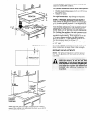
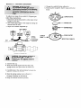
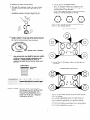
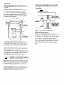
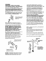
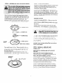
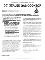
INSTALM’TION
INSTRUCTIONS
Before you begin— Read these instructions
these instructions
IMPORTANT-OBSERVE
Note to Installer-Be
Note—This
completely
these instnzctions
must be properly
with the Consumer.
with your Use and Care Book for future reference.
grounded.
.. ......... ...... . . .. . ..
. . ..... . .... .
WARNING: If the information ‘inthis manual is
not followed exactly, a fire or explosion may
resu[t causing
property damage, personal
injury or death.
—
—
●
In Canada, electrical grounding must be in accordance with the current CSA/C22. 1 Canadian Electrical
Code Part 1 and/or local codes. See Electrical Connections.
not store or use ~ascke
or other
flammable
vapors and fiquids in the
vicinity of this or any other appliance.
“ Be sure (he installation of this cooktop in a mobile
home conforms with the .Manufactureci 130me Cons[rur tion and %lkly S(andarci, Title 24 CFI<, [)art 3280. If lli:s
Stanciarci does Ilot apply, you must fo]]ow’ the standfir(i
for .Manufactured I-iorne installations AYSI .X225. 1 an(i
.Manufactured Home Installations, Si(es. and Communities ANSI /NFPA 501A or with local codes.
WHAT TO DO IF YOU SMELL GAS
●
●
●
—
●
This cooktop must be electrically grounded in accordance with local codes, or in their absence, with d:e
National Electrical Code ANSI/NFPA No. 70-Latest
Edition. See Grounding Instructions on page 6.
‘ Do
●
Do not try to light anY afmliance.
.Do not touch any electrical switch: do
not use any ph&e in your building.
hnmediately
tail your gas s~plier
from a neighbor% Phone. Follow the
gas supplier’s inskctions
.
In Canada. mobile home installation must be In
accordance w;ih the current C/WT/CSA 22-10/311+Ilobile
Home Installation Code.
lf you cannot reach your gas supplier,
call the fire department
lnstailatian
and
service
must
performed by aqudifiedinstaller,
agency or the gas suppfier.
IMPORTANT
SAFETY
use.
CODES AND ORDINANCES.
sure to leave these instructions
appliance
NEW
and carefully.
for locai inspector’s
ALL GOVERNING
Note to Consumer—Keep
YOUR
GAS CX)OKTO
Hum
IMFORTANT4ave
FOR
●
Do not store Items of interrst to children in cabinets
above the rook[op. TIley coLI1d I)e serioL]sly b~lmcci
climbing on (he rooktop to reach !I)cfll.
be
sewice
c To eliminate reaching over surlhce t)[lrners,
storage above burner should be avolde(i.
(’2~)i
Ilt’[
●
Adjust surface burner ilame sue so ]( (im:s r)ot t>xle:!~i
beyon(i the edge of the cooking u[ensil.
INSTRUCTIONS
s ~3ie\rer
use your cooktop for warllllr]C or llea[il~: [llc
room, Prolonged use of the cooktop \vlt~loLiLadeqLlate
L’entdation can be hazardous,
This cooktop has been design certified by The American
Gas Association according to ANSI 221.1 latest edition
and The Canadian Gas Association according to C.&N/
CGA- 1.1 Latest Edition. You’ll find safety precautions
in your Use and Care book. Read them carefully.
TOOLS YOU WILL NEED
For cutting countertop—saber
saw
For gas supply connection—pipe
wTenches
For conversion from Natural to Propane ~as—acij~lst:~blc
open-end \vrench and 7mm socket driver or 9/32’
nuldriver
For burner Ilaxllr :ldjL]s[rllent—I)llilli[)s
hea(i :In(i i;lcl,ic
type scrc~vcint”ers
Installation of this cooktop must conform with local
codes, or in the absence of local codes, with the INationai Fuel Gas Code, .&ITSI 2223.1 -Latest Edition.
●
●
In Canada. installation must conform with [he
cur-rent Natural Gas Inst.aJlation Code. C.-LY/CG.+E3149.1 or the current Propane Installation Code, C.YX,’
CGA-B149.2. and ;vlth local codes \vhere applicable.
ADDITIONAL MATERIALS YOU MAY NEED
●
Be sure your cooktop is lnstaIled properly l)]” a
qualified installer or serivce technician.
Gas
1
line shLl[-oif J’al\’e
:
Pipfe; olrlt
s
11 2“ pIpCJ nlpl)ie
srai.ln[
Provide adequate clearances between cooktop and
adjacent combustible surfaces.
For fkxible
.
I
I
35 1/2’
●
I
I
I
I
I
For
connection
where
local
codes
permiti
Flexible metal tubing (same 3/4” or 1/2” I.D. as
gas supply line)
Adapter or union
rigid
connection:
Pipe fittings as required.
STEP 2: PROVIDE ADEQUATE GAS SUPPLY
1-
This cooktop is designed to operate on natural gas
at 4“ of water column pressure. It is shipped from
the factory set for natural gas.
~..aL#,
FOR PROPER OPERATION, THE MAXIMUM INLET
PRESSURE ‘IO THE REGULATOR MUST BE NO
MORE THAN 14” OF WATER COLUMN PRESSURE.
For checking the regulator, the inlet pressure must
be at least 1” (or 3.4 KPA) greater than the
regulator output setting. If the regulator is set for
4“ of water column pressure, the inlet pressure
must be at least 5“. If the regulator is set for 1O“,
the inlet pressure must be at least 1l“.
2 1/4”
%
The gas supply line to the cooktop should be 1/2”
or 3/4” pipe.
In Canada, flexible connectors must be single walI
metal connectors no longer than 6 feet in Iength.
1 “ FROM BACKWALL
I
JI
t-
V
PROPANE GAS ADJUSTMENTS
NOTE: The pressure regulator is set for natural
gas. To use Propane Gas, the regulator must be
converted.
12 1/2”+
T
FROM CUTOUT
CENTER LINE
I
I
I
I
I
i 30”MIN.
TOCABINET
1,
I
1
3 3/4” MIN.
I CLEARANCE
L
18’MIN.
‘TO CABINET
Make sure the w~ coverings, countertop and cabinets
around the cooktop can withstand the heat (Lip to 200°F)
generated by the cooktop.
2
MAKING L.P. /PROPANE CONVERSION
4. Change
the cooktop burner orifices by:
A. Removing
the top grates, burner caps and burner
heads.
To adjust your range for use with L. P./Propane
follow these instructions:
1. Disconnect all electrical
breaker or fuse box.
gas,
BURNER
power, at the main circuit
2. Shut off the gas supply to the range by closing the
manual shut-off valve.
3. Adjust the Pressure
GRATE
BURNER CAP
Regulator by:
BURNER
HEAD
CAP GASKET
P.,o.yx?
I
.
.
r
BURNER
BOWL ~
SPRING
RETAINER
/
L.PJPROPANE
POSITION
“**mmm
r----,
q.-----,
..-4
---
1,
I
I
I
‘y’ +
\-------
1====,
I
I
I
I--”,_.
I
I
I
I
---‘--’
-- i ---- l====;
I
I
I
i----l
PRESSURE
i\
11
Iy
REGULATOR
A. Unscrew the cap.
B. Place your thumb against the flat side of the
spring retainer and press down to remove the
retainer.
C. Carefully look at the spring retainer to locate the
NAT or L. P./Propane position.
D. Turn the spring retainer over so that L. P./
Propane is showing on the bottom.
E. Snap the retainer back into posi(ion.
3
SPARK IGNITER
ER TUBE (CHIMNEY)
B. Remove the valve control knobs.
5.
Locate the L.P. /Propane orifices
C. Through the openings, locate the valve bypass
screws located on the lower right side of the
valves.
The L.P. /Propane oritlces are shipped in the
literature package. They will have a digit number
and the letter “L” on one side.
D. Using a screwdriver,
Each orifice will also show a series of engraved
marks, (I, 11or III), located on the top.
clockwise
screw down fully, in a
rotation, the brass bypass screw.
00(2
These marks denote the precise location of each
orifice to the cooktop burner.
GLASS COOKTOP
E. Using a 7mm or 9/32” nut driver, remove the top
burner orifices. These may be accessed through
the burner air/gas mixer tube (chimney).
MIXER TUBE (CHIMNEY)
NOTE:
The ofilces
have a spring loaded retaining
ring around the hex head to hold the ori~lce
in the nut driver during installation
and
removal.
A slight amount of force is
required to push the nut driver down over
the ring.
!3
RETAINER
RING
SPECIAL
NOTE:
To convert the range back to
natural gas, use the orifices that
you removed during the L.P./
Propane conversion
and reverse
steps 1-6 of the L. P./ Propane
conversion
section.
6. Install the L. P./Propane
locations.
PORCELAIN
orifices in their precise
COOKTOP
Adjust the low [lame setting using the valve bypass
scre’,v as follows:
Lo\v setting adjustments must be made with t~vo
other burners in operation on a medium setting.
This procedure pre~rents the low flame from being
se[ too low resulting in the flame belnq extinguished
~vhen other burners are turnecl on.
IMPORTANT
Remove all packing material and literature from
cooktop before connecting gas and electrical supply
to range.
FOR INSTALLATION
OVER A BUILT-IN OVEN:
See Buiit-in Oven Installation for complete
instructions.
STEP 3: CONNECT THE COOKTOP TO GAS
1. Connect
the cooktop to the gas suppIy line.
2. Install a manual shutoff valve in the gas line in
an easily accessible location outside the cooktop.
Be sure you know how and where to shut off the
gas supply to the cooktop.
r19
5“ TO CENTER
OF 2“ DIA W
FROM COUMERTOP
1/2” CUTOUT-q
g&/
STREET EL
3“
14
L
CABIN=
SiD
STEP 4: ELECTRICAL CONNECTION
Electrical
L
3. Check for leaks. After connecting range to gas,
check system for leaks with a manometer.
If a
manometer is not available, turn the gas supply on
to the range and use a liquid leak detector at all
joints and connections to check for leaks.
Tighten all connections if necessary to prevent gas
leakage in the range or supply line.
Check alignment of valves after connecting the range
to the gas supply to be sure the manifold pipe has
not been moved. A misalignment could cause the
valve knob stem to rub on the control panel,
resulting in a gas leak at the valve.
Disconnect
this range and its individual shutoff
valve from the gas supply piping system during any
pressure testing of that system at test pressures
greater than 1/2 psig.
Isolate the range from the gas supply piping system
by closing its individual shut off valve during any
pressure testing of the gas supply system at test
pressures equal to or less than 1/2” psig.
Requirements:
Because of potential safety hazards under certain
conditions we strongly recommend against the use of
an extension cord. However, if you still elect to use
an extension cord, it is absolutely necessary that it
be a UL listed 3-wire grounding type appliance
extension cord and that the current caqing
rating
of the cord in amperes be equivalent to or greater
than the branch circuit rating. Such extension
cords are obtainable through your local appliance
dealer.
GROUNDING
~
IMPORTANT:
(Please read carefully)
FOR PERSONAL SAFETY, THIS APPLXANCE
MUST BE PROPERLY GROUNDED.
The power cord of this appliance is equipped with a
three-prong (grounding) plug which mateswith a
standard three-prong grounding wall receptacleto
minimizethe possibilityof electricshock hazard from
this appliance.
The customer should have the wall receptacle and
circuit checkedby a qualKled electricianto make
sure the receptacleis properlygrounded.
UNLESS THE SCREW IS METAL, AND NOT
INSULATED, AND THE WALL RECEP17ACLE IS
GROUNDED THROUGH THE HOUSE WIRING. l%IE
CUSTOMER SHOULD HAVE THE CIRCUIT
CHECKED BY A QUALIFIED ELECTRICIAN K)
MAKE SURE THE RECEPTACLE IS PROPERLY
GROUNDED.
When disconnecting the power cord fmm the
adaptor, always hold the-adaptor with one hand. If
this is not done the adaptor ground terminal is very
likely to break with repeated use. Should this
happen, DO NOT USE the appliance until a proper
ground has again been established.
USAGE SITUATIONS WHERE APPLIANCE POWER
CORD WILL BE DISCONNECTED
FREQUENTLY.
Insure proper ground
and firm connection
before use.
Do not use an adaptor plug in these situations
because disconnection of the power cord places
undue strain on the adaptor and leads to eventual
failure of the adaptor ground terminal. The
customer should have the two-prong wall receptacle
replaced with a three-prong (grounding) receptacle
by a qualified electrician before using the appliance.
Where a standard two-prong wall receptacle is
encountered, it is the personal responsibility and
obligation of the customer to have it replaced with a
properly grounded three-prong wall receptacle.
In Canada, mobile home installation must be in
accordance with the current CAN/CSA Z240/MH
Mobile Home Installation Code.
DO NOT, UNDER ANY CIRCUMSTANCES,
CUT OR REMOVE THE THIRD (GROUND)
PRONG FROM THE POWER CORD.
STEP 5: INSTALLING UNIT IN A STANDARD OR
TILE COUNTER
USAGE SITUATIONS WHERE THE APPLIANCE
POWER CORD WILL BE DISCONNECTED
INFREQUENTLY.
Before installing the unit in the cutout, attach the
adhesive backed foam tape (shipped with unit)
around the bottom surface of the glass, near the
edge of the maintop.
For 15 amp circuit only, do not use an adaptor on a
20 amp circuit. Where local codes permit, a
TEMPORARY CONNECllON
maybe made to a
properly grounded two-prong wall receptacle by the
use of a UL listed adaptor available at most
hardware stores. The larger slot in the adaptor
must be aligned with the large slot in the wall
receptacle to provide proper polarity in the
connection of the power cord.
To attach the unit to the counter, insert the hold
down brackets in the slots on each side of the unit.
Use the screws supplied to attach unit to counter as
shown. The unit must rest on the metal flange
arounci the burner box and not on the glass.
MOUNTING
Insure proper ground
and firm connection
before use.
,
BOX
P+fj
10
d ‘ “.
I/
O:“~
/
j2’i+.usE
Align large
prongs/slots
SUITABLE
,
l!
/1
Temporary method
(Adaptor plugs not
permittedin Canada)
Yj
CAUTION: ATllACHING THE ADAPTOR GROUND
TERMINAL
~
THE WALL RECEPTACLE COVER
SCREW DOES NOT GROUND THE APPLIANCE
SIDES
0
‘, .
FASTENERS FOR
ANCHORING IN
CABINET SIDES
STEP 6: ASSEMBLING
THE COOKTOP BURNERS
STEP 7: CHECK THE IGNITERS
Operation of electric igniters should be checked after
cooktop and supply line connectors have been
carefully checked for leaks and cooktop has been
connected to electric power.
Place the bumerhead
onthebumerkwl,
so that
the location of the spark igniter matches up with the
opening in the burner head. Position the burner cap
on the burner head. Place the burner grate over the
burner assembly and into the burner bowl. The
bottoms of the burner grates have fingers that fit into
the corresponding indentations in the burner bowl.
BURNER GRATE
o
T
<—.
II,4
To check for proper lighting, push in and turn a
burner valve to the LITE position. The burner valve
should light when gas is available to burner. Once
the burner lights, it should be turned out of the LITE
position. TV each valve separately until all burners
have been checked out.
BURNER IGNITION
COOKTOP SPARK IGNITION — When you turn the
cooktop knob to LITE, the spark igniter makes a
series of electric sparks (ticking sounds) which light
the burner.
During a power failure the burners will not light
automatically.
In an emergency, a cooktop burner
may be lit with a match by following the steps below,
BURNER CAP
<—
BURNER HEAD
SPARK IGNITER
BURNER
BOWL ~
ER TUBE (CHIMNEY)
Turn each burner full on. Flames should be blue in
color with no trace of yellow. Foreign particles in the
gas ]ine may cause an orange flame at first but this
will soon disappear.
The burner flames shoulcl not flutter or blow a~vay
from the burner. The inner cone of the Ilame should
be between 1/2” and 3/4” long.
1. Light a match and hold the flame near the burner
yoLl want to light. Wooden matches work best.
2. push in and turn the control knob slowly. Be
sure you are turning the correct knob for the burner
yoLl are lighting.
NOTE: If the burner does not light within five
seconds, turn the knob off and wait one minute
before trying again.
STEP 8: WHEN ALL HOOKUPS ARE
COMPLETED
MAKE SURE ALL CONTROLS
POSITION.
ARE LEf7 IN THE OFF
MAKE SURE THE FLOW OF COMBUSTION AND
VENTILATION AIR TO THE RANGE IS UNOBSTRUCTED.
MODEL AND SERIAL NUMBER LOCATION.
px::P
\
-q
1-1/2”
to 3/4”
The serial plate for your cooktop is located on the
bottom of the burner box. In addition to the model
anti serial numbers, it tells you the ratings of the
burners and type of fuel and pressure the cooktop
was adjusted for when it left the factory.
When ordering parts, always include the serial
nunlber, model number and code letter to ensure
proper replacement parts. Parts may be obtained
thI-oLlgh General Electric /HotPoint FactoIy Semite
Cerlters or General Electric/Hotpoint
authorized
Cuslomer Cclre semicers.
NOTES
Q>
~$
Pub. No. 31-10169
229c4053P03$I
RecycJed Paper
—
Printed in LaFayette, Georgia —