1
User
-
s
Manual-
Electric Ranges
51
8900
Vl
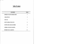
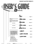
Table of Contents
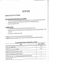
COI{TENTS
PAGE
IMPORTANT SAFETY INSTRUCTIONS
3
COOK-TOP USE
5
OVEN USE
7
HO\ry TO OPERATE THE OVEN
I
SETTING THB CLOCK AND TIMER
8
GENERAL CARE AND CLEANING
9
BEFORE YOU CALL SERVICE
t2
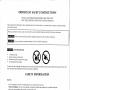
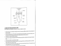
IMPORTAI\T SAFETY INSTRT]CTIO]\S
READ ALL INSTRUCTIONS BEFORE USING THIS LTNIT
SAVE TI]ESE INSTRUCTIONS FOR FUTURE REFERENCE
'I'his manual mttst be followed to reduce potential
risk of fire, electric shock, ol to prevent ir¡ur.y to pel.solls or.pr.operty da¡rage
when usir.rg the range.
Please pay attention to these words, which
ifilhÑfÑG
will alelt you about harrnful
sitr-rations, ancl
follow all give¡ instr.uctio¡s:
It rnay cause seliously harm, death or property clamage if you do not follow instructions.
film¡'t¡lÑllt
may cattse injury or propelty danrage if you clo not follow instructior.rs.
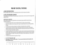
ülttiñlññ ANrr-rrp
DBvr c E
All ranges can tip,
L¡uly to persons could result.
a
a
Install anti-tip clevice packed with range,
See lnstallation Instructions.
a
a
To reclttce the risk of tipping, the range must be secured by properly installed anti-tip bracket provi¿ecl with the ra¡ge. please refer
to the anti-tip blacket installation instnlctions for proper installation.
SAFETY INFORMATIOI\
General:
a
a
a
a
a
a
a
a
'
'
'
¡
use this appliance only for its intendecl pulpose as described in this rnanual.
Proper Installation - Be sttre your appliance is properly installed and grounded by a qualif,red technician.
Never use your appliance for warming or heating the room.
Do not leave children alone - Children should not be left alone or unattencled in l.he area where appliance is in use. They
should never be allowed to sit or stand on any part ofthe appliance,
Wear proper apparel - Loose-f,rtting or hanging garments shoulcl never be worn while using the appliance.
User servicing - Do not repair or replace any part of the appliance unless specifioally recomrnenclecl i¡ this rnanual. All other
selvicing shoulcl be referred to a qualified technician.
Storage in or on appliance - Flamrnable rnaterials should not be stoled in an oven, storage ch'awer or near surface units.
Do not use water on grease fires - Surother fire or flame, or use dly chernical or foarn-type extingLrisher.
Use only dry potholders - Moist or darnp potholdels ou hot surfaces may result in bur¡s fi'om steam. Do ¡ot let potholclers
touch hot heating elernents. Do not use a towel or other bulky cloth.
EeliS[NG Dã not allow anyone stepping, leaning or sitting on the dool or storage clrawel of this r¡nit. It may <iarnage the
range ancl could tip it over, resulting in serious burns or other injury.
IEIEIIN. Do nor stot'e itetls of interest to children in the cabinets above a range or on the back gr,rard of a lange - chilcL.en
clirnbing on the range to leach iterns could be seriously injured.
DO NOT TOUCH SURFACE UNITS, AREAS NEAR TI{ESE UNITS, HEATING ELBMENTS OR IN'|ERIOIì
SURFACES OF TllE OVEN. Both sulfaces units ar.rd oven heating elernents may be hot even thor.rgh they a¡e dark i¡ color,
Areas neal'sttt'face trnits and intelior sttrfaces of an oven rnay become hot enough to cause bLu.ns. Dirring á¡d after use, clo not
tottch, or let clothing or other flamurable llaterials contact surface units, areas near units, heati¡g ele¡reirts or inter.ior. surfaces
of oveu until they have had sufficient time to cool. Aurong these surfaces ale the oook top, surfÀces facing the cook top, the
oven vent opening and surfaces near this oper.ring, oven door al.rcl window.
r
'1
,
¡
Surface Cooking Units:
.
Glazed cooking utensils - Only certain types of glass, glass/ceramic, ceramic, ealthetrware, or other glazed utensils ale
suitable fol lange-top service without breaking due to the sudclen change in temperature.
Utensils handles should be turned inward and not extend over adjacent surface units -- To reduce the risk of burns,
ignition of flarnmable materials, and spillage due to unintentional contact with the utensil, the handle of a utensil shor"rld be
positioned so that it is turned inward, and does not extend over adjacent surface units.
Use proper pan size - This appliance is equipped with one or-more sulface units of cliff'erent size. Select t¡tensils having flat
bottorns large enough to cover the surface unit-heating element. The use of undersized utensils will expose aportion of the
heating element to clilect contact and may result in ignition of clothing. Proper relationship of utensils to burner will also
improve efficiency.
Never leave surface units unattended at high heat setting - Boil-over causes smoking ancl gleasy spillovels that rnay ignite.
.
.
.
For Coil Surface Elements Cook-top models:
o Make sure reflector pans or drip bowls are in place - Absence of
these pans ol' bowls during cooking rnay subject
wiring or cornponents underneath to darnage.
o Protective liners - Do not use aluminum foil to line surface unit drip bowls or oven bottoms, except as suggested in
the manual, Improper installation of these liners rnay result in a risk of electric shock, or fire.
o Do not soak removable heating elements - Heating elements should never be irnmersed in water.
o Clean the cook top with caution - If a wet sponge is used to wipe spills on a hot cook top, be careful to avoid steam
burns.
o To avoid the possibility of a burn ol electric shock, always be certain that the controls fol all surface units are at the
OFF position ancl all coils are cool before atternpting to lift or remove a nnit.
For Ceramic Glass Cook-top models:
o Do not cook on broken cook top
- Ifcook top should break, cleaning solutions and spillovers rnay penetrate the
broken cook top ancl create a risk of electric shock. Contact a qualif,red technician irnrnediately.
o Never use the glass cook-top surface as a cntting area.
o Be carefi¡l when placing spoons or other stirring utensils on glass cook-top surface when it is in use. They may
become hot and could cause burns.
o Do not place or store iterns that can rnelt or catch f,rre on the glass cook-top, even when it is not being used.
o Clean cook top with caution - If a wet sponge ol cloth is used to wipe spills on a hot cooking area, be careful to
avoid a steam burn. Sorne cleaners can produce noxious frunes ifapplied to a hot surface.
o Do not to leave a hot lid on the cook-top - As the cook-top cools, air can becorne trapped between the lid and the
cook-top and the ceramic glass could break when the lid is rernoved.
o Do not cook foods directly on the cook-top surface without a pan.
o Do not drop heavy or hard objects on the glass cook-top, they rnay cause it to craok.
Oven:
.
¡
¡
¡
Use care whcn opening oven door - Let hot air or steam escape before removirlg or replacing food.
Do not heat unopened food co¡rtai¡rers - Build-up of pressure may cause container to bulst and result in injuty.
Keep oven vent ducts rrnobstrr"rctecl.
Placement of oven racks - Always place oven racks in desired location while oven is cool. If rack must be moved while oven
is hot, do not let potholdel contact hot heating element in oven.
COOK-TOP USE
SETTING SURFACE CONTROLS
the
a
a
.
Place cooking utensil on the sr"rrface eletnent'
push in and tnrn the sr.rrface control knob in either direction to the desirecl setting, Start rnost cool,<1ne,o1e1iT::,:::.llTl"i
knobs do not have to be set exactly on a patticular setting use
setting a,,d turn to a lower setting to finish .ooting. The contlol
the setting as a guide and adjust them as needed'
the pan'
Whe' cooking is cotnpletecl, trtln the sut'face element off before removing
elernents are tttrned on' A quick glance at this indicatol
Note: The surface elernent on indicator light will glow when one or more
ale ttrrned off'
light when cooking is frnished is an easy way to bé sr'rle all srtrface elements
a
a
.
sized cookware on the radiant surface element'
"oit".tly
setting' Start most cooking opttut19l:,:.1 "-,llïl"i
push in
and tnrn the surface control knob in either direction to the desired
not hive to be set exaotly on a particular setting' use
clo
knobs
contlol
The
setti.g and turn to a lower setting to finish .ooking.
"Each
A
surface element provi<les a constant amonnt of heat at each setting'
the settings as a guicle and adjust them as needed.
for
srnall
too
is
cookware
cookware inclicates the
glowing red surface heating area extending beyoncl the bottom edge of the
Plu."
the sr.rrface heating area.
the pan'
When cooking is completed, turn the surface element off before removing
glance at this inclicatol
elements are turned on' A quick
Note: The surface elemert on i'dicator light will glow when one or rrore
a'e tnrnecl off. The hot strrfaoe indicator light will
light when cooking is hnishecl is an easy way to bã sure all surface elements
glow until the heating sttrface area has cooled
ancl
will
continue to glow after the control knob is turned to the oFF position
suffioiently.
Iìadiant surface elernents rîay appear to have cooled after they have been
cooled sufficiently'
hot and burns may occru'if the glass surfaoe is touchecl before it has
m$¡ffñ
ù lJ lulùIrù
I Du
D
turned off. The glass surface rnay still be
u r\r' Õ
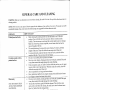
Usethefollowingchartasaguide'h"n,.ttingffitt,,.gsar.ebasedoncookinginrnedittm-weightrnetalparrswith
They may vary when using other types of pans'
RECOMMENDED USE
SETTING
HIGH (HI
-
Start rnost foods, bring water to a boil, pan broiling
9)
MEDIUM HIGH (7 MEDTUM (5
-
-
4)
- l)
Note: The size a'd type of utensil
cooking results.
Continue a rapicl boil, fry, deep fat fry
vegetables
Maintain a slow boil, cook soups, thicken satlces ancl gravies, steanr
6)
MEDTUM LOV/ (2
LOW (LO
8)
Keep foods cooking, Poach, stew
Keep food warnr, melt, simmer
usecl ancl the arnount and
type of food being cooked will infllrence the setting needed for best
COIL ELEMENTS AND BURNER BOWLS (Coil Surface Elements Cook-top Models)
.
Surface units should be level for optirnal cooking results. Dlip bowls, when clean, reflect heat back to the cookware.
They also help catch spills.
.
Cookware should have flat bottorns that make good contact with the entile surface unit. Check for flatness by rotating
ruler across the bottorn. There should be no gaps between the utensil and the ruler.
.
Utensil sizes shor"rld match with surface unit size. Pans should cover the entire elernent to absorb the maxiurum heat.
Avoid using an undersized utensil that would expose a portion of the surface unit, resulting in serious burns or clothing
a
ignition.
.
Pans shor.rld not extend more than one inch over the coil element. The boftorn surface of the pan in this situation could
trap enough heat to cause discoloring of the burner bowl, damage to the surface units ancl or crazing of the porcelain
enarnel range surface.
CERAMIC GLASS (Ceramic Glass Cook-top Models)
.
¡
.
.
.
The surface cooking area
selected heat level.
will glow red when
an element is on.
It will cycle on and off,
at all settings, to maintain the
Wiping off the cook-top before and after each use will help keep it free frorn stains and provide the most even heating.
For rnore information, see "Care and Cleaning" section.
Use cookware about the same size as the surface cooking area. Cookware should not extend rnole than one inch outside
the area.
Use flat-bottorned cookware for best heat conduction and energy efficiency. Cookware with rounded, warped, ribbed or
dented bottoms could cause uneven heating and poor cooking results.
Detennine flatness by placing the straight edge of a Luler, no space ol' Iight shoulcl be visible between it and the
cookware.
--l
{
r
T
OVEN USE
I
BEFORB SBTTING OVEN CONTROL
*
r
Vent
Whentheovenisol1,warlnairflowsthroughtherightreat.
in the oven and good baking resttlts'
element. This venting i, n.".rtuty foi prop.. air circulation
DO NOT BLOCK OVEN VENT.
ì
I
I
Arranging Oven Racks
.
.
o
:
tulning the oveu on'
T.,
l-ssitl" burns, place racks in the desile position before
"""td
they will stop before co'ring cornpletely or'rt' and
s'pports,
the
on
Racks have stop-locks, so that when praced "orr".ìly
will not tilt.
Do not rnove racks with bake ware on thetn'
edge and slide out'
To remove, putl the rack out until the stop position, raise the front
of the rack trpward and slide it back into place'
front
the
Tilt
walls.
oveí
the
on
guides
the
To replace, fit the r.ack onto
Recommended Rack Positions for Broili
Baki
and
RACK POSITION
FOOD
I or2
Broiling meats, chicken or ftsh
2or3
Cookies, cakes, pies, biscuits and muff,tns
Broiling fish, rnedium steaks, hamburgers
2
q{h"p'
J
Broiling well-done foods strch as chicþn :ncllobsler
F-r"n
pies, angel food cake, yeast bread,
4
"utt"@
4
Tnrkey, toast or ham
Air Circulation into the Oven
. T"
food evenly, hot air must
.
¡
be able to circulate'
"ook
inches of space aronncl bake ware
For. best air circulation and baking results allow two
an<l
be sul'e palls ancl bake ware clo
not toucheach other, the oven door, sides or back ofthe oven cavity.
in the oven for even heat to reach arottnd the foocl'
The hot air.rRust circulate ar.or.rnd the pans and bake ware
POSITION ON RACK
NUMBER OI- PANS
Centet' of rack
Side by side or slightlY staggered
3 or'4
each ru.k, Mo
-pposite colners on
HOW TO OPERATE TTIE OVEN
IIfiEfn
The oven inclicator light will glow when there is electlic power to the bake element. When the oven temperature setting
is leached, the indicator light will go off. lt lights up again when the powel cornes back on the bake elernent.
The oven indicator lighf glows until the oven reaches your selected ternperatuLe, then goes OFF and ON with the oven elernent(s)
during cooking.
Bakine
Before baking, positions racks and bake ware according to "Arranging oven racks and
1.
Ail cilculation in the oven"
sections.
2.
Preheat the oven before start baking. To preheat, set the oven at the correct ternperature. Preheating is necessary for good
results when baking oakes, cookies, pastry and breads. Pleheat the oven for l0 rninutes.
Tuln the oven control clockwise to the ternperature setting desired. Check food for doneness at the rninirnum time shown
3.
in the recipe. Cook longer ifnecessary.
Tuln the oven control knob OFF when cooking is complete.
Broiline
Before broiling, position rack ¿rccording to "Arlanging oven racks" section.
To broil, tuln the oven control clockwise to BROIL. It is not necessary to pleheat the oven unless recommended in the
recipe. Position food on broiler pan provided with the lange. It is designed to drainjuices and help prevent spatter and
smoke. Close the door to the broil stop position to ensure propcr broiling ternpelature.
Broil on one side until foocl is browned, turn and cook on the second side. Always pull the rack ou¡t to the stop position
before turning or rernoving food.
Turn the oven control knob OFF when cooking is complete.
fil$nõÑ
Should an oven fite occuL, close the oven door and turn OFF the oven. If the fire continues, use a fire extinguisher.
DO NOT put water or flour on the fire. Floul may be explosive.
SETTING THE CLOCK AI\D TIMER (Some Models)
TO SET THE CLOCK
o
e
¡
Pless and hold the CLOCK pad.
Press the UP or DOWN ARIìOW pads to select the tirne of day.
Press the CLOCK pacl to start.
TO SET THE TIMER
.
¡
¡
Press the TIMER pacl.
Press the UP oI DOWN ARROW pacls to increase ol declease the time in one-rninute inclernents. Press and hold the pacls to
increase or decrease the tirne in lO-minute increments. The tirner can be set for any amount of tirne from 00:01 rninutes to
I l:59 hours.
Press the TIMER pad to start.
NOTES: The tirner does not start or stop cooking. It serves as an extla tirner in the kitchen that will beep when the set time has nrn
oLrt. While the tirner is active, press and holcl the UP or DOWN ARROW pads to inclease or cleclease the time. To cancel the tinrer
before the set time has run out, pless the CLOCK pad.
GET\ERAL CARE AI\D CLEANING
WARNING: Make
sure you disconneot your stove befole cleaning, Be caleful
if it is hot. Always follow label instrLrctions on
cleaning prodr.rcts.
product can sttffet'
IMPORTANT: Do not use any type of abr.asive sponge for the cleanliness of any surface of your stove. The
consiclerable damages. Soop,
*uié. and a soft cloih or sponge are suggested filst unless otherwise noted.
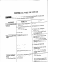
SURI-ACES
HOW TO CLEAN
Co¡rtrol panel and knobs
Porcelain enamel surfaces,
painted surfaces
.
.
.
a
a
Oven cavity
(OJO:ESTE TEXTO SOLO
APLICA PARA MODELOS
ELECTRICOS)
.
.
Oven heating elements
Before cleaning the control panel be sure that the knobs are oD TURN OFF
position. Clean with cloth ancl warln soap water. Remove residttes and dry
carefully. The water excess in atld around the contlols might cause stove damage'
Make sule of rernoving cleaners completely to avoid stains which are hal'd to
relÌ)ovc thlotrghotrt the tilne.
The control knobs rnay be removecl fol easier cleaning. Trl Lemove, pLrll thern
straight off the stern. Clean with cloth and warm soap watel'. Rinse well'
To relocate the knobs, make the flat side of the k¡ob cavity coincide with the
control rod flat side. Then, iust press the knob inside
Be sure to weat'rttbber gloves to protect yor-rr hands.
Do not use oven cleaners, cleaning powders, steel wool pads, synthetic fiber pads
or any other matelials that rnight darnage the sulface finishing'
Ifany aci<l, grease, sugar, etc. spills on surfaces while they are hot, use a dry papel
towei or cloih to wipe it up light away. When the surface has cooled, clean with
cloth and warln soap water. Rinse well.
Also it is possible to use vinegar ancl water solution'
Fleavy spatteling or spillovers rnay require cleaning with a mild abrasive cleanel
Use vinegat' to t'etnove hard stains (white stains
Do not ,,r" oven cleaners, cleaning powders, steel wool pads, synthetic fiber pads
or any other rnaterials that might datnage the surface finishing'
To clean the oven bottom, gently lift the bake element' This will allow easier
access to the oven bottorn for cleaning. Be carefr-rl not to raise the elelneut more
than 4 to 5 inches from the resting position
water. Rinse and dry with clean towel.
Clean with warm
elernents. Any soil will burn off when the elements
heating
the
oven
not.l"un
no
ale heatecl.
(OJO: ESTE TEXTO SOLO
APLICA PAIìA MODELOS
ELECTRICOS
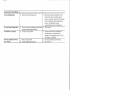
Oven racks
Broiler pan
.
.
.
¡
Oven light (on some modcls)
a
a
l,ift-ofï oven door
of vegetable oil or'
with it.
lacks
the
of
the
edges
towel and wipe
cookins oil to a
pour orrt the
ancl
carefully
n"r'rlou. ttt" broiler pan frorn the oven after bloiling
containet'.
grease t'om the pan into a proper
Wash and rinse the broiler pan using hot water and a soap-filled scouring pad.
If food has bulned on, splinkle with detergent while it is hot and covet'it with wet
paper.towels or a dishcloth. Soaking the pan will remove burned-on food'
Also it is possible to rtse viuegar and water solution.
Do not nse cornmercial oven cleaners, cleaning powclers, steel wool pads or harsh
abrasives on any sttrfaces.
tterins or srrillovers may requile cleaning with a rnild abrasive cleaner.
Hea
B.fr" r'"plu.ing the oven light bulb, be sttre than oven light switch is ttrln OFF'
f-"uL" tt . racks slicle rnole easily apply a small amottnt
.
Replace bulb with a 4O-watts household appliance bulb
The oven cloor is rernovable for cleaning.
l'Iow to rerrove:
.
o
Operr the door to the fully opened position.
Pull tro the lock located on both hinge stt
ts and
it in
the hook of the
hinge levers. You may have to apply a little downward pressure on the door to pull
the lock fully over the hooks.
Grasp the cloor by the sides; pLrll the bottom of the door trp and towarcl yor,r to
disengage the hinge supports. Keep pulling the bottom of the door toward you
while rotating the top of the door toward the range to corlpletely disengage the
hinge levers.
How to replace:
.
Proceecl in Leverse to reinstall the door. Make sule the hinge supports are
fully
engaged before unlocking the hinge levers.
Ilow to clean the inner door:
. Soap and water will norrnally do the job. Heavy spattering or spillovels rnay
require cleaning with a lnild ablasive cleaner.
¡
Use a glass cleaner to clean the glass on the inside of the door' (on some models)
How to clean the outer door:
.
.
Use soap and water to thoroughly clean the top, the bottom, sides and front of the
oven door. Rinse well.
Do not let water drip into the vent openings.
Use a glass cleaner to clean the glass on the outside of the door on some models
10
BEFORE YOU CALL FOR SERVTCE
comlrìorl
It may save you time ancl expense' The list includes
Before you call for-service, r.eview this list.
wo'ktna'ship o' materials in this applia'ce'
occurfences that are noi,i" result of <lefective
ñilTrdT¡tfsûr
U.ments Or Oven Not
Ñ".f**
SOLUTION
POSSIBLE CAUSE
OCCURRENCE
Will Operate
2¡ Sr,rfacc Elements Do Not Heat
b)
rrrru
Make sttre corcl plug ls pluggeo LlBrrLry
grounded outlet
i horlset.tol¿ ftlse been blown or has the circuit
c)
breaker been triPPed
Service wiring is not complete'
d)
Power otttage.
a)
a)
Replace the fuse ol reset the circuit'
b
Contact yout'dealer, installing agent or
authorizcd service
ôn."t tlo"t. lights to bc sure' Call your local
c
electriccompany@
Usc orrly flat, cvcllly balancco, lncorurrt ur
bcttcr
hcavywcight cookwarc' Flat pans hcat
iitoni*pãa pans. Cookwarc nraterials and
weight oi thc matcrial affect heating' Heary
anclïediurn-weiglrt parrs heat eveuly' Bccause
pans hcat uneveuly, foods rnay
'I
Lightwcight or warpcd pans tlsco
Properly
l
lightweight
b)
No powcr to thc aPPliance'
c)
hrcorrect control setting.
The surface ttnits are not plugged in solidly
d)
r)
burn easilY.
(1)
Check steps ttndet' Occurrence
:)
Makc sttt'c thc corrcct control is on for thc
Ð
With controls off, check to make surc the
into the
stlrface ttnit in plugged completely
surfacc rtttit to bc ttscd'
l
'-
rcccntaclc.
f¡ n.ip Borvls Are Pitting Or
Rusting
(Coi1 SuLface Elements Models)
arr(
Foods with acìds, sttch as tolnarocs, rr
to stand in/on bowls will catrse cot'rosioti'
)
b)
Environmeut.
wash dlip bowls as soo' as
^nd
possiblc altcr a sPillovct"
;--0)R.*"".
b)
salt.air'
Flouscs along scacoast arc cxposcd to
Þrotcct bowfs as lnttch as possitrlc lrorn dircct
cxflostllc to salt air'
.^" .^trc high cnough tcrìlpcraturcs to
cookware
^)--Tltlt
discolor the drip bowls DO NOT use
to the
matched
be
shoulcl
oitf"t ,Vp.. Pan sizes
clcllcnt
thc
of
sizc
,
?Þ.i-LBot"lt Are Turning Color
0r Distorted
a)
Bottom srttfàcc ot coc
sttrf'acc
srufacc clcnrclrts and tonchcs cook-top
(Coil Surface Elelnents Models)
5) S.'.atches lJr Abrasions On
.) C"**
b)
c)
6)
a)
Mctal Marks
tl
,qt
*,
Of Discolorations With
(Celamic Glass Cook-top Moclels)
Surface Indicator Light
On
Stays
(Córamic Gtass Cook+oP Models)
10) Frcquent CYcling OIT
Surf¿rce Ullits
And On
) ilc,uræ.i''lñõrcl
c_ì
Lr*c srnooth. flat-þottoln,cd
I
a)
Mincral deposrts lrolr
^ì--
r'oocl
I
a)
cookwÎtc
,.,,..,,
utcnsils on cook-top sr'll'lacc
""irlt¿.rl*tal
crcarn to
Usc a cctatnic glass cook-top clcaning
lnarks
.
thc
,-ernouc
--,,
Usc a razor bladc scrapcr to rcllìovc sorr'
O"
|
F) Uil*k*nc
I
Rcl'ovc
of
b)
I
a)
bottorns
utc,trils at'e clcan bcl'olc ttsagc srnall scratchcs
less
do not affect cooking and will becotne
visible witli titne'
Check them.
ñ-'
Sliding or scrapll-tg ol lÌelal tlrenslr
Boil-ovcls arc cooked ollto stll'racc
Metallic Sheen
ffit
a
Cleaning nraterials not recommendecl for
c.ranric-gluss cool(-top havc bccn lscd'
Cookwaic with rough bottotrr lras bccn usecl
top sut'face
(ôcrarnic Glass Cook-toP Modcls)
7) Bt'utnn Strcaks Or SPecks
rôctrmic Glass Cook-top Mo49!!)-
as salt or sand bctwccn
cook-top ancl tltcnsils cilll carlsc scratcltcs'
Cook-toP Surface
(Ceramió Glass Cook-toP Moclels)
p.t1"lcs strch
:::
::
with clcan' clry boltotns'
cream
using a ceran-ric glass cook-top cleaniug
inclicirtor light stay orì altcr
t:ontrol l<nob(s) havc bccn tulnccl OFF'
Tl* lt"t"ñcc
a) Itnpropcl cookware bcing used/
-tc'ancì
1l
a)
Chcck it.
a)
Usc only flat cooltwat'c to minirnize cycling'
I1) Poor Baking Results
a)
Many faotors affect baking results.
a)
Make sule thc ploper rack position is used.
Ccr-rter food in the oven and space pans to
allow ail to cilculate. Allow the ovelì to preheal
to the set tenlperature bcforc placing foocl in
the oven. Try adjusting the recipes
recolnr-nerrded telnnel'atrìre or bakins time.
l2) Oven Makes Clicking Noise
a)
a)
This is norrnal
l3) Oven Door ls Crooked
a)
This is the sonnd of the heating elerlent tulning
off and on during cooking functions.
The door is ont ofposition
a)
a)
b)
Replace ol tiglrten bulb.
Switch oDeratins lisht is broken.
a)
Elecanse the oven door is removable; it is
sornetirnes gets or¡t of position duling
installation. To straighten tl-rc door, see "Care
and Cleanins" in this Guide.
See "Care ancl Clcaning" in this Guide.
b)
Call for Selvice.
14) Oven
Light Does Not Work
lSome Models)
12
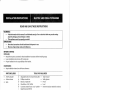
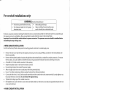
READ AND SAVE THESE INSTRUCTIONS
WARNING:
.
.
lf the information in this manual is not followed exactly, a fire or electrical shock may result causing
property damage, personal injury or death.
This appliance must be pronerlv qrounded.
IMPORTANT:
.
Save these instructions for the local electrical inspector's use.
BEFORE STARTING
INSTALLER:
.
¡
.
Read all instructions contained in these installation instructions before installing range,
Leave installation instructions with homeowner.
Proper installation is the responsibility of the installer.
HOMEOWNER:
.
Keep installation instructions for future reference.
TOOLS YOU WILL NEED
PARTS INCLUDED
¡
.
.
Anti-Tip bracket
Anchor sleeves
Bolts
.
.
'n
.
Adjustable wrench or channel lock pliers
Phillips
Electric or hand
Wood floors:3/16" drill
Concrete/ceramic floors: 13/32" carbidetipped masonry drill bit
3/8" nut driver
screwdriver
drill
bit
o
I
.
.
.
.
Tape measure
Safety glasses
Pencil
Level
.
Hammer (may be needed for anchors)
MPORTANT SAFETY INSTRUCT¡ONS
WARNING! For personal safety, remove house fuse or open circuit breaker before beginning installation.
Failure to do so could result in serious injury or even death.
.
.
All clearances and spacing dimensions must be met for safe use of your range.
Be sure your appliance is properly installed and grounded by a qualified technician.
ANTI-TIP DEVICE
WARNING! To reduce the risk of tipping, the range must be secured by properly installed anti-tip bracket
provided with the range.
All ranges can tip.
. lnjury to persons could result.
. lnstall anti-tip device packed with range.
. See lnstallation lnstructions.
lf you pull the range out and away from the wall for any reason, make sure the Anti-Tip bracket is engaged when the range
is pushed back aoainst the wall.
PREPARE TO INSTALL TFIE RANGE
A. REMOVE SHIPPING MATERIALS
Remove packaging materials. Failure to remove packaging materials could result in damage to the appliance.
b. TNSTALLATTON REQUIRED CLEARANCES
provide adequate clearances between the range and adjacent combustible sudaces. Check for proper electrical supply and the
stability of the floor.
Cabinet dimension requirements
Follow all dimension requirements provided bellow to prevent property damage, potential fire hazard and incorrect
countertop and cabinet cuts.
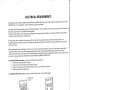
. The range may be placed with 0" clearance at the back wall and 0.5" clearance at side walls of cabinet.
. Make sure the cabinets and wall covering around the range can withstand temperatures (up to 200"F) generated by
the range.
. 30" minimum clearance between cooking surface and bottom of unprotected wood or metal cabinet
1/c" flame retardant
24" minimum clearance when bottom of wood or metal cabinet is protected by not less than
millboard covered with not less than No. 28 MSG sheet steel, 0.015" stainless steel, 0.024" aluminum or 0.020" copper.
a
18" minimum clearance upper cabinet to countertop,
a
To reduce the risk of burns or fire when reaching over hot suface elements, cabinet storage space above the cook-top
should be avoided. lf cabinet storage space is to be provided above the cook-top, tlre risk can be reduced by installing
a range hood that sticks out at least 5" beyond the front of the cabinets. Cabinets installed above a cook-top must be
no deeper than 1 3".
1" minimum to wall on either side of range above 36" height.
a
a
A=2O" or 30" (it depends the model)
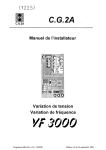
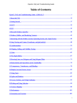
Wall receptacle - 8" to 22" from either cabinet, 7 Vz" max. from floor. Orient the electrical receptacle so the
length is parallel to the floor.
nt-l
TYPICAL CABINET INSTALLATION
ELECTRICAL OUTLET AREA
€. ANTI-TI P BRACKET
¡NSTALLATION INSTRUCTIONS
To reduce the risk of tipping of the range, the range must be secured to the floor by properly installed anti-tip bracket and
screws packed with the range. Failure to installthe anti-tip bracket will allow the range to tip over if excessive weight is place
on an open door or if a child climbs upon it. Serious injury might result from spilled hot liquids or from the range itself.
lf range is ever moved to a different location, the ant¡-tip bracket must be also moved and installed with range.
lnstructions are provided for installation in wood or cement fastened to the floor. When fastening to the floor, be sure that
screws do not penetrate plumbing.
Anti-tip bracket installation:
1.
2.
3.
4,
5.
6.
7.
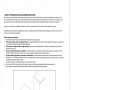
The anti-tip bracket must be installed to hold the right rear leg of range.
lf the range is place into a range opening, place the anti-tip bracket so that the closed edge of the bracket is against the
rear wall and its right side against cabinet adjacent.
lf the range is not place into a range opening, just place the anti-tip bracket so that the closed edge of the bracket is
against the rear wall.
To mount anti-tip bracket to wood floor, use the bracket to mark where to drill mounting holes. Use a drill with a 1/8"
drill bit to drill the two holes. Use the two screws provided to fasten anti-tip bracket to floor.
To mount anti-tip bracket to concrete or ceramic floor, use the bracket to mark where to drill mounting holes. Use a
drill with a3/16" drill bit to drill the two holes. Tap plastic anchors into mounting holes in floor with hammer. Line up holes
in anti-t¡p bracket with holes in floor.
Use the two screws provided to fasten anti-tip bracket to floor.
Move range close to opening. Plug the power supply cord into the grounded outlet and gas supply line.
Move range into position making sure right rear leveling leg slides into anti-tip bracket.
Rear leveling
leg
Anti-tip
bracket
Slide Range
back
I
r
r
ELECTR¡CAL REQUIREMENTS
*
with the National Electrical code
This range must be properly installed and grounded by a qualified technician in accordance
ANSI/NFÞA No. 70 - latest editionl - and Local Electrical code requirements.
I
Kit" to the proper electrical voltage and
This range must be connected by means of "permanent wiring" or "Power supply cord
frequency as specified on the model/serial rating plate.
that is properly installed and grounded in
lf using a power supply cord, the plug must be p-lugged into an appropriate outlet
accordance with all local codes and ordinances.
permanent wiring system; or an
lf using a direct wire connection, this range must be connected to a grounded metal,
equipment-ground terminal or
equipment-ground conductor must be run with the circuit conductors and connected to the
lead on the range.
wire in the range compartment
when installing permanent wiring, do not leave excess wire in range compartment' Excess
hazard if wires become
potential
electrical
a
create
could
properly
and
may alloy the Rear Access Cover tã be replaced
conduit or range cable use flex
flexible
using
wh"n
connections".
"permanent
wire
under
pinched. connect only as instructed
tonnector or range cable strain relief. NOTE: USE COPPER OR ALUMINUM CONDUCTORS
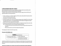
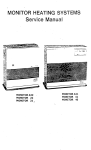
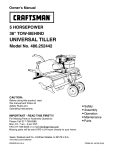
To remove the Rear wire cover is necessary to follow these instructions:
1. Remove the main top from the range
2. Remove the screw A located as is showed on Figure 1
3. Remove the screws B and C located on Rear wire cover as is showed on Figure 2
4. Take the cover offfrom the range
To replace the Rear wire cover proceed in reverse. Make sure the cover
is
fully engaged'
Remove the
screw A
Figure
I
Figure 2
A. MODELS WITH FACTORY CONNECTED POWER SUPPLY CORD
power supply cord. lt
Some models may be equipped with a factory connected four (4)-conductor
prohibited'
is
conductor
appliance will be installed *h"t" grounding through the neutral
Ì Copies of standards listed may be obtaìned from:
National Fire Protection Association
BatterYmarch Park
QuincY, Massachusetts, 02269
is
to be used when the
I
1
a
;
b. MoDELS REQUtRING POWER SUppLY CORD KtT
RISK OF FIRE OR ELECTRICAL SHOCK MAY OCCUR IF AN INCORRECT SIZE RANGE CORD KIT IS USED, THE INSTALLATION
INSTRUCTIONS ARE NOT FOLLOWED OR STRAIN RELIEF BRACKET IS DISCARDED.
This appliance may be connected by means of a power supply cord. Only a power supply cord kit raled 120/240 volts,40
amperes and marked for use with ranges shall be used.
.
.
r
.
Use only a 3-conductor or a 4-conductor UL-listed range cord. These cords must be provided with closed-loop terminals
on wire and a strain relief device properly installed.
A time-delay fuse or circuit breaker is recommended.
Local codes may permit the use of a Ul-listed, 250 volt, 40 amp range power supply cord (pigtail) This cord contains three
No. 10 copper wires and matches a 3-wire receptacle of NEMA Type 10-50R. Connectors on the appliance end must be
provided at the point the power supply cord enters the appliance.
The range can be connected directly to the fused disconnected (or circuit breaker box) through flexible armored conduit.
Allow 2 to 3 feet of slack in the line so that it can be moved if servicing is ever necessary.
o An UL-listed conduit connector must be provided at each end of the power supply cable (at the range and at the
junction box)
o Wire sizes and connections must conform to the rating of the range (40 amp)
The wiring diagram is located on the back of the range in a bag.
For power cord ¡nstallations only:
WARN ING:
r
.
Electrical Shock Hazard
Disconnect power before servicing. | .
Use a new 40Amp power supply cord. | .
Plug into a grounded outlet.
Failure to follow these instructions can
result in death, fire or electrical shock.
Assemble the strain relief in the hole. lnsert the power cord through the strain relief and tighten. Allow enough slack to easily
attach the cord terminals to the terminal block. lf tabs are present at the end of the winged strain relief, they can be removed
for better fit.
lmportant: Do not install the power cord without a strain relief. The strain relief bracket should be installed before
reinstalling the rear range wiring cover.
3-CONDUCTOR POWER CORD INSTALLATION
Use this method only if local codes permit connecting cabinet-ground conductor to neutral wire of power supply cord.
.
.
'
'
.
.
.
.
¡
.
.
Remove the wire cover (on the back of range) by removing 3 screws using a Phillips screwdriver. The terminal block will
then be accessible.
Remove the knockout ring (1 3/8") located on bracket directly below the terminal block. To remove the knockout, use a
pair of pliers to bend the knockout ring away from the bracket and twist until ring is removed.
Assemble a U.L.-listed strain relief in the opening.
lnsert the power supply cord through the strain reliel allowing enough slack to easily attach the wiring to the terminal
block.
Use only ring terminals to connect the power supply.
Use a1/q" nut driver and remove the hex washer head nuts from the terminal block.
Connect the outer wires to the outside terminals and the center wire to the center terminal. Securely tighten nuts for
proper electrical connection. Do not remove the ground strap.
Tighten the strain relief screws.
Re-install the wire cover with the 3 screws removed earlier. Make sure the wires do not become pinched between the wire
cover and main back.
FACTORY INSTALLED CONNECTIONS
-CONDUCTOR POWER CORD I NSTALLATION
is required.
Use this method for new installations and whenever 4-conductor installation
.
.
.
.
.
.
¡
.
¡
.
.
Phillips screwdriver. The terminal block will
Remove the wire cover (on the back of range) by removing 3 screws using a
then be accessible.
block. To remove the knockout, use a
Remove the knockout ring (1 3/8") located on bracket directly below the terminal
pair of pliers to bend the [.nockout ring away from the bracket and twist until ring is removed.
Assemble a U.L.-listed strain relief in the opening.
the wiring to the terminal
the power supply cord through the strain reliel allowing enough slack to easily attach
lnsert
block.
Use only ring terminals to connect the power supply'
screw' Bend the ground link away from the
Remove the ground-link screw from the range frame. Save the ground-link
range so that it does not contact the range.
ground wire must
ground wire from power supply cord to the range using the ground-link screw' The
Connect the green
be attached flrst and must not contact any other terminal'
block.
Use a1/q,, nuldriver and remove the hex washer head nuts from the terminal
terminal. Securely tighten nuts for
center
the
to
wire
center
Connect the outer wires to the outside terminals and the
proper electrical connection.
Tighten the strain relief screws'
do not become pinched between the wire
Re-install the wire cover with the 3 screws removed earlier. Make sure the wires
cover and main back.
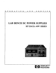
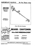
CONNECT i.INE
HERË
1
CONNECT NEUTRAL
GROUND STIìAP
For eor'¡duit installations only:
¡
n
WARNING: Electrical shock Hazard
Disconnect power before servicing. I o Electrically grand range.
Use 8-gauge copper wire or 6-gauge | .
Failure to follow these instructions can
aluminum
,
wire.
I
result in death, fire or electrical shock.
Purchase a squeeze connector matching the diameter of your conduit and assemble it in the hole. lnsert the conduit through
the squeeze connector and tighten. Allow enough slack to easily attach the wires to the terminal block.
lmportant: Do not install the conduit without a squeeze connector. The squeeze connector should be installed before
reinstalling the range wiring cover.
I
l
3-WIRE CONDUIT INSTALLATION
Use this method only if local codes permit connecting ground conductor
.
.
.
.
.
.
.
.
.
¡
to neutral supply wire.
Remove the wire cover (on the back of range) by removing 3 screws using a Phillips screwdriver. The terminal block will
then be accessible.
Remove the knockout located on bracket directly below the terminal block as needed for conduit connection. To remove
the knockout, use a pair of pliers to bend the knockout ring away from the bracket and twist until ring is removed.
Assemble a U.L.-listed conduit connector in the opening.
Strip the insulation back 1 inch from the end of each wire.
Use only ring terminals to connect the power supply.
Allow enough slack in the wire to easily attach the wiring terminal block.
Use a1A" nu| driver and remove the hex washer head nuts from the terminal block.
Connect the line wires (1 and 2) to the outside terminals and the neutral wire to the center terminal. Securely tighten nuts
for proper electrical connection. Do not remove the ground strap.
Tighten the locking ring of the conduit connector.
Re-install the wire cover with the 3 screws removed earlier. Make sure the wires do not become pinched between the wire
cover and main back.
4- WIRE CONDU¡T INSTALLATION
Use this method for new installations and whenever 4-conductor installation is required.
.
¡
,
.
.
.
.
.
o
o
.
¡
u
"
Remove the wire cover (on the back of range) by removing 3 screws using a Phillips screwdriver. The terminal block will
then be accessible.
Remove the knockout located on bracket directly below the terminal block as needed for conduit connection. To remove
the knockout, use a pair of pliers to bend the knockout ring away from the bracket and twist until ring is removed.
Assemble a U.L.-listed conduit connector in the opening.
Strip the insulation back 'l inch from the end of each wire.
Use only ring terminals to connect the power supply.
Allow enough slack in the wire to easily attach the wiring terminal block.
Remove the ground-link screw from the range frame. Save the ground-link screw. Bend the ground link away from the
range so that ¡t does not contact the range.
Connect the green ground wire from power supply cord to the range using the ground-link screw. The ground wire must
be attached first and must not contact any other terminal.
Use a1/c" nul driver and remove the hex washer head nuts from the terminal block.
Connect the line wires (1 and 2) to the outside terminals and the neutral wire to the center terminal. Securely tighten nuts
for proper electrical connection,
Tighten the locking ring of the conduit connector.
Re-install the wire cover with the 3 screws removed earlier. Make sure the wires do not become pinched between tlre wire
coverand main back.
OPERATING POSIT¡ON
Be sure
into final location'
to provide all adequate clearances and dimensions before moving range
into and fully engaging the anti-tip bracket' Make sure
carefully slide range into final position while insefting rear leveling leg
drawer. Be sure to check the level of the range'
the power cord folds into tt-ì" åmaining area behind the range storage
OPËRATION CHECKLIST
indicator light glow' Turn the unit off when glow is detected'
Turn on one of the surface units to observe that the element and
Recheck the range wiring connections.
lf range does not oPerate:
. check that the circuit breaker is not tripped or the house fuse blown.
cord is plugged into outlet'
" Check that the power supply
¡ See Use and Care Manual for troubleshooting list'