1
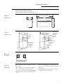
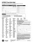
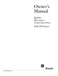
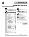
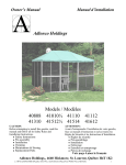
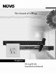
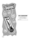
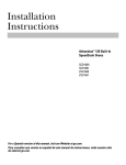
Installation
Instructions
Built-In
Microwave/Convection
and
Microwave Ovens
Models
ZMC1095
JEB1095
JEB1055
Before you begin – Read these instructions completely and carefully.
IMPORTANT: Save these instructions for local inspector’s use.
IMPORTANT: OBSERVE ALL GOVERNING CODES AND ORDINANCES.
NOTE TO INSTALLER: Be sure to leave these instructions with the consumer
NOTE TO CONSUMER: Keep these instructions with your Use and Care Book for future reference.
If you have questions concerning the installation of this product, call the GE Answer
Center® Consumer Information Ser vice at
800.626.2000, 24 hours a day, 7 days a week.
Proper installation is the responsibility of the
installer. Product failure due to improper
installation is not covered under the GE
Appliance Warranty. See the Use & Care
Guide for warranty information.
If you received a damaged oven, you should
contact your dealer.
Important
Safety
Information
Safety Instructions
This product requires a three prong
grounded receptacle. The installer must
perform a ground continuity check on the
power outlet box before beginning the
installation to insure that the outlet box is
properly grounded. If not properly grounded,
or if the outlet box does not meet the
electrical requirements noted, (under
ELECTRICAL REQUIREMENTS), a qualified
electrician should be employed to correct any
deficiencies.
CAUTION: For personal safety, remove house fuse or oven circuit
breaker before beginning installation to avoid severe or fatal
shock injury.
CAUTION: For personal safety, the mounting surface must be
capable of supporting the cabinet load, in addition to the added
weight of this 70 pound product, plus additional oven loads of up
to 50 pounds or a total weight of 120 pounds.
CAUTION: For personal safety this product cannot be installed in
cabinet arrangements such as an island, a peninsula or below
a countertop.
Electrical Requirements
Product rating is 120 volts AC, 60 Hertz, 13
amps. and 1.45 kilowatts. This product must
be connected to a supply circuit of the proper
voltage and frequency. Wire size must conform to the requirements of the National
Electric Code or the prevailing local code for
this kilowatt rating. The power supply cord
and plug should be brought to a separate 15
or 20 ampere branch circuit single grounded
receptacle. The outlet box should be located
near the cord entry point. The outlet box and
supply circuit should be installed by a qualified electrician and conform in the National
Electric Code or the prevailing local code.
Usage: Can be installed over any GE single
electric built-in oven.
Contents
Design Information
Product Dimensions ......................................................................................................................................................................... 3
Cutout Dimensions ........................................................................................................................................................................... 3
Electrical Locations ......................................................................................................................................................................... 3
Advance Planning ............................................................................................................................................................................ 3
Installation
Installation Option ............................................................................................................................................................................ 4
Tools and Materials Required ........................................................................................................................................................ 4
Parts Supplied ................................................................................................................................................................................... 4
Step 1, Slide Microwave into the Cutout ...................................................................................................................................... 4
Step 2, Remove Grille Retainer Screws ........................................................................................................................................ 5
Step 3, Install Side Trim for 30" Appearance ............................................................................................................................... 5
Step 4, Drive Installation Screws .................................................................................................................................................. 5
Step 5, Reinstall Grille ...................................................................................................................................................................... 6
2
Design Information
Built-In Microwave/Convection Oven
Models ZMC1095, JEB1095, JEB1055
Available in White, Black and Stainless Steel
29-3/4" With Optional Side Trim
Product
Dimensions
16-3/8"
26-3/4"
15-3/8"
18-5/8"
13/16"
27" or 30""
Cutout
Dimensions
27" or 30""
18"
25-1/4"
17" Min.
for Flush
Outlet
25-1/4"
Construct Base
Min. 3/8" Plywood
Supported by
2 x 4 or 1 x 2
17" Min. Runners, all
for Flush Four Sides
Outlet
17-1/2"
17-1/2"
Construct Base
Min. 3/8" Plywood
Supported by
2 x 4 or 1 x 2
Runners, all
Four Sides
36" Min.
Electrical
Location
24"
1-7/8" Min.
Per Oven
Requirement
45-1/4"
6"
8"
Locate outlet box in the shaded area
Advance
Planning
These microwave ovens are sized to fit a 27"
wide cabinet.
• Side trim pieces are provided for installation
into a 30" wide space. For a matching
appearance, use the side trim when installing
the microwave oven above a 30" single wall
oven.
• If you are installing into a 27" wide cabinet,
or over a 27" wide wall oven, discard the side
trim pieces.
• Cutout dimensions are the same for both 27"
or 30" wide cabinet installations.
3
Installation
Built-In Microwave/Convection Oven
Installation
Options
These built-in ovens can be inset into the
cabinetry. In this installation the microwave is
recessed and flush with the front surface of
the cabinet.
A shadow box affect can be achieved by
installing a rail at the top and bottom of the
microwave to fill the cutout height. In this
installation, exposed inside surfaces of the
cabinet should be finished to match the
cabinet surface.
• In both a recessed and shadow box
installation, the floor of the cutout must be
level and even with the bottom edge of the
cutout. Use runners inside the opening to
raise the floor to matching height.
Top
Rail
26-3/4"
4-1/4"
1"
26-3/4"
18-5/8"
11"
Bottom
Rail
13/16" x 13/16" Sq.
Stopper Strip 4 sides
1
Step
Slide the
Microwave
into Cutout
Inset/Recessed Installation
• Cut 4 stopper strips, 13/16" square to frame
the opening, install the strips 13/16" from
the front edge of the opening. Oven overlap
will cover all 4 stopper strips.
Shadow Box Installation
• Cut top and bottom rail to fit the width of
the opening. Cut the height of the rails to fit
the cutout height. Use cleats to secure the
rails to the inside walls of the cabinets.
Tools and Materials required:
•#2, Phillips screwdriver
• 2 each #8x1" - Round head
•Hand held drill motor
wood screws
•High speed drill bit, 1/8"
• 3/8", slothead screwdriver
diameter
Parts supplied:
• 2 mounting screws
• 4 extra side trim screws
• 2 side trim pieces
• Lift and hold the oven up to the opening.
• Hold the oven at the 45° angle and plug in
the power cord.
• Carefully, slide the oven into the cabinet.
• Check to be sure that power cord is not
trapped under the bottom or the sides of the
oven.
4
Design Information
Built-In Microwave/Convection Oven
2
Step
• Open the door.
• Remove the two (2) retainer screws from the
bottom side of the grille (one at each side).
Remove Grille
Retainer Screws
• Roll the grille forward from the bottom.
• Disengage the locating tabs, and remove the
grille from the unit.
Note: Grille appearance varies
depending on model.
3
Step
Install Side
Trim for 30"
Appearance
SKIP THIS STEP
IF YOU ARE NOT
USING THE
OPTIONAL
SIDE TRIM.
4
Step
Drive
Installation
Screws
If you are installing in a 27" opening, skip this
step and discard the optional side trim.
For a 30" installation appearance:
• Slide one side of the oven out of the opening
about 4" to 5", leaving the opposite side
against the cabinet. The oven should be at
about 30° angle in the opening which will
allow easier access to the side trim screws.
• Remove the two side trim screws.
• Hold a side trim piece against the oven with
screw holes aligned. Reinstall original screws.
Note: 4 extra side trim screws are provided for your convenience.
• Lift the oven by the bottom, pull out and
turn the oven to expose the opposite side.
CAUTION: LIFT THE OVEN FROM THE BOTTOM. DO NOT
LIFT THE OVEN WITH THE SIDE TRIM.
Side trim will not support the weight of the oven.
• Remove the two side trim screws and install
the opposite side trim piece.
• Carefully, lift the oven by the bottom and
slide straight back into the opening. Check
to be sure power cord is not trapped beneath
the oven.
• Using the installation holes as a guide, drill
two (2) pilot holes (1/8" diameter) into the
cabinet.
• Install the two (2) installation screws.
CAUTION: Place tape or
cardboard over trim edges to
prevent damage while drilling
pilot holes.
5
Installation
Built-In Microwave/Convection Oven
5
• Reinstall the grille, with the two retainer
screws.
Step
Reinstall
Grille
6
Notes
Built-In Microwave/Convection Oven
7
Pub. No. 49-8978
SPECIFICATIONS SUBJECT TO CHANGE WITHOUT NOTICE
DWG. NO. 164D3333P205
(N.D. 322) 5/99
Printed in Korea