1
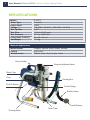
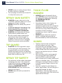
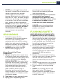
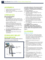
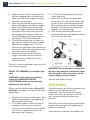
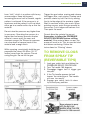
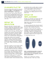
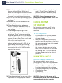
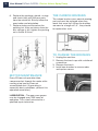
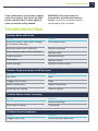
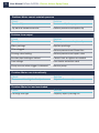
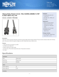
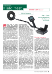
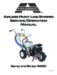
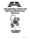
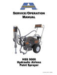
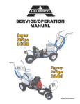
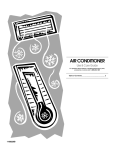
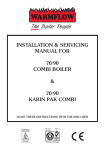
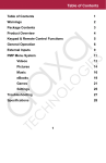
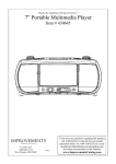
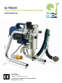
Q-TECH
Q-P019 ELECTRIC AIRLESS SPRAY PUMP
USER MANUAL
CAUTION!
This manual contains
important warnings and information
PLEASE READ & KEEP FOR FUTURE REFERENCE
ISSUE DATE 31.05.2014
2
User Manual Q-Tech Q-P019 - Electric Airless Spray Pump
SPECIFICATIONS
Model
Motor Type
Power input
Voltage
Max Tip Size
Max Flow
Max Pressure
Dimensions (LxWxH)
Net Weight
Q-P019
Universal
700W
110-120V~ 50-60Hz , 220-240V~ 50-60Hz
0.021”
1.9 l/min (0.42 gpm)
207 bar (3,000 psi)
36 x 25 x 40 cm
11.4 kg
Material Applications
Wood interior
Ceiling
Wood exterior
Lacquer, Varnish, Stain, Sealer, Enamel,
High-build,
Exterior stain, Vinyl, Acrylic, Latex
Carry Handle
Pressure Adjustor Knob
Brush Cap
Fuse
Packing Nut
On/Off Switch
Outlet Fitting
Suction Hose
Inlet Strainer
Drain Tube
Priming Valve
www.aristospray.com
GENERAL SAFETY RULES
WARNING! Read and understand all
instructions. Failure to follow all
instructions listed below may result in
electric shock, fire and / or serious
personal injury. The term airless sprayer in
all of the warnings listed below refers to
your mains-operated (corded) airless
sprayer.
b)
SAVE THESE
INSTRUCTIONS
c)
Work area
d)
a) Keep your work area clean and well
lit. Cluttered benches and dark areas
invite accidents.
b) Do not operate airless sprayers in
explosive atmospheres, such as in
the presence of flammable liquid,
gases, or dust. Airless sprayers
create sparks which may ignite the
dust or fumes.
c) Keep bystanders, children, and
visitors away while operating a
airless sprayer. Distractions can
cause you to lose control.
e)
properly grounded. If the sprayer
should electrically malfunction or break
down, grounding provides a low
resistance path to carry electricity
away from the user.
Avoid body contact with grounded
surfaces such as pipes, radiators,
ranges and refrigerators. There is an
increased risk of electric shock if your
body is earthed or grounded.
Do not expose airless sprayers to
rain or wet conditions. Water entering
an airless sprayer will increase the risk
of electric shock.
Do not abuse the cord. Never use
the cord for carrying, pulling or
unplugging the airless sprayer. Keep
the cord away from heat, oil, sharp
edges or moving parts. Replace
damaged cords immediately.
Damaged or entangled cords increase
the risk of electric shock.
When operating an airless sprayer
outdoors, use an outdoor extension
cord suitable for outdoor use. Use of
a cord suitable for outdoor use
reduces the risk of electric shock.
Personal Safety
Electrical Safety
a) Airless sprayer plugs must match
the outlet. Never modify the plug in
any way. Do not use any adapter
plugs with earthed (grounded)
airless sprayers. Unmodified plugs
and matching outlets will reduce the
risk of electric shock.
Grounded sprayers must be plugged
into an outlet properly installed and
grounded in accordance with all
codes and ordinances. Never
remove the grounding prong or
modify the plug in any way. Do not
use any adaptor plugs. Check with a
qualified electrician if you are in
doubt as to whether the outlet is
a) Stay alert, watch what you are doing
and use common sense when
operating an airless sprayer. Do not
use while you are tired or under the
influence of drugs, alcohol, or
medication. A moment of inattention
while operating airless sprayers may
result in serious personal injury.
b) Use safety equipment. Always wear
eye protection. Safety equipment
such as dust mask, non-skid safety
shoes, hard hat, or hearing protection
used for appropriate conditions will
reduce personal injuries.
c) Avoid accidental starting. Ensure the
switch is in the off position before
plugging in.
3
4
User Manual Q-Tech Q-P019 - Electric Airless Spray Pump
d) Do not overreach. Keep a proper
footing and balance at all times. This
enables better control of the airless
sprayer in unexpected situations.
e) Dress properly. Do not wear loose
clothing or jewellery. Keep your hair,
clothing and gloves away from
moving parts. Loose clothes, jewellery
or long hair can be caught in moving
parts.
Service
Have your airless sprayer serviced by a
qualified repair person using only
identical replacement parts. This will
ensure that the safety of the airless
sprayer is maintained.
If the supply cord of this airless sprayer
is damaged it must be replaced by a
specially prepared cord available
through the service organization.
SPECIFIC SAFETY
RULES
HANDLE THIS UNIT AS YOU WOULD A
LOADED WEAPON!
Extreme high pressure spray can cause
extremely serious injury.
OBSERVE ALL WARNINGS!
WARNING: HIGH PRESSURE. Never
leave pressurized system unattended.
Always follow the Pressure Relief
Procedure. Take precautions to avoid high
pressure component rupture.
DANGER: INJECTION INJURY. Skin
injection by high pressure paint is not a
simple cut. It must be treated surgically
immediately.
WARNING: FIRE AND EXPLOSION
HAZARD. Take all precautions to avoid
sources of sparks and ignition when
spraying. Keep the machine at least 6
meters away from the spraying operation.
WEAR PROTECTIVE EQUIPMENT AT
ALL TIMES. Always use a respirator, eye
protection and protective clothing.
Keep clear of moving parts when starting
or operating the sprayer. Do not put your
fingers into any openings to avoid
amputation by moving parts or burns on
hot parts. When starting the motor,
maintain a safe distance from moving
parts of the equipment.
Before adjusting or servicing any
mechanical part of the sprayer, follow the
PRESSURE RELIEF PROCEDURE.
EXPLOSION RISK FROM
HALOGENATED HYDROCARBON
SOLVENTS
Never use halogenated hydrocarbon
solvents in this machine.
Contact with aluminum parts may cause
an explosion.
Some of the most common of these
solvents are:
Carbontetrachloride
Chlorobenzene
Dichloroethane
Dichloroethyl Ether
Ethylbromide
Ethylchloride
Tethrachloethane
www.aristospray.com
PREVENT STATIC
SPARKING
FIRE/EXPLOSIONS
Vapors created when spraying can be
ignited by sparks.
To reduce the risk of fire, always locate the
sprayer at least 20 feet (6 m.) away from
spray area. Do not plug in or unplug any
electrical cords in the spray area. Doing so
can cause sparks which can ignite any
vapors still in the air. Follow the coating &
solvent manufacturers safety warnings
and precautions.
MEDICAL ALERT - Airless Spray
Injection Injuries
If any fluid appears to penetrate your skin,
GET EMERGENCY MEDICAL CARE AT
ONCE.
DO NOT TREAT AS AN ORDINARY CUT.
High pressure fluids from spray or leaks
are powerful enough to easily penetrate
the skin and cause extremely serious
injection injury, leading to the possible
need for amputation.
• NEVER point the spray gun at anyone
or any part of the body.
• NEVER put your hand or fingers over
the spray tip. Do not use a rag or any
other materials over your fingers. Paint
will penetrate through these materials
and into the hand.
• NEVER try to stop or deflect leaks with
your hand or body.
• ALWAYS have the tip guard in place
when spraying.
•
•
•
•
•
•
•
•
•
•
•
•
•
ALWAYS lock the gun trigger when
you stop spraying.
ALWAYS remove tip from the gun to
clean it.
NEVER try to "blow back" paint, this is
not an air powered sprayer.
ALWAYS follow the PRESSURE
RELIEF PROCEDURE before cleaning
or removing the spray tip or servicing
any system equipment.
Be sure the equipment safety devices
are operating properly before each use.
Tighten all of the fluid connections
before each use.
NEVER alter equipment in any manner.
NEVER smoke while in spraying area.
NEVER spray highly flammable
materials.
NEVER use around children.
NEVER allow another person to use
sprayer unless he is thoroughly
instructed on its safe use and given
this operator’s manual to read.
ALWAYS wear a spray mask, gloves
and protective eye wear while
spraying.
ALWAYS ensure fire extinguishing
equipment is readily available and
properly maintained.
NEVER LEAVE SPRAYER UNATTENDED
WITH PRESSURE IN THE SYSTEM.
FOLLOW PRESSURE RELIEF
PROCEDURES
ALWAYS INSPECT
SPRAYING AREA
•
•
•
Keep the spraying area free from
obstructions.
Make sure the spraying area has good
ventilation to safely remove vapors and
mists.
NEVER keep flammable material in
spraying area.
5
6
User Manual Q-Tech Q-P019 - Electric Airless Spray Pump
•
•
NEVER spray in vicinity of open flame
or other sources of ignition.
The spraying area must be at least 20
ft. away from spray unit.
TOXIC FLUID
HAZARD
•
SPRAY GUN SAFETY
•
•
•
•
•
ALWAYS set gun safety lock in the
"LOCKED" position when not in use &
before servicing or cleaning.
NEVER remove or modify any part of
the gun.
ALWAYS REMOVE THE SPRAY TIP
when cleaning. Flush unit at the
LOWEST POSSIBLE PRESSURE.
ALWAYS check operation of all gun
safety devices before each use.
Be very careful when removing the
spray tip or hose from the gun. A
plugged line will contain fluid under
pressure. If the tip or line is plugged,
follow the pressure relief procedure
TIP GUARD
•
ALWAYS have the tip guard in place
on the spray gun while spraying. The
tip guard alerts you to the injection
hazard and helps prevent accidentally
placing your fingers or any part of your
body close to the spray tip.
•
•
HOSES
•
•
SPRAY TIP SAFETY
•
•
Use extreme caution when cleaning or
changing spray tips. If the spray tip
clogs while spraying, engage the gun
safety latch immediately. ALWAYS
follow the PRESSURE RELIEF
PROCEDURE and then remove the
spray tip to clean it.
NEVER wipe off build up around the
spray tip.
ALWAYS remove tip guard & tip to
clean AFTER pump is turned off and
the pressure is relieved by following
the PRESSURE RELIEF
PROCEDURE.
Hazardous fluid or toxic fumes can
cause serious injury or death if
splashed in eyes or on skin, inhaled or
swallowed. Know the hazards of the
fluid you are using. Store & dispose of
hazardous fluid according to
manufacturer, local, state & national
guidelines.
ALWAYS wear protective eyewear,
gloves, clothing and respirator as
recommended by fluid manufacturer.
•
Tighten all of the fluid connections
securely before each use. High
pressure fluid can dislodge a loose
coupling or allow high pressure spray
to be emitted from the coupling and
result in an injection injury or serious
bodily injury.
Only use hoses with a spring guard.
The spring guard helps protect the
hose from kinks or other damage
which could result in hose rupture and
cause an injection injury. Do not allow
kinking or crushing of hoses or allow it
to vibrate against rough, sharp or hot
surfaces.
Use only conductive fluid hoses for
airless applications. Be sure the gun is
grounded through the hose
connections. Use only high pressure
airless hoses with static wire which are
approved for 3000 psi.
www.aristospray.com
•
•
NEVER use a damaged hose, which
can result in hose failure or rupture and
cause an injection injury or other
serious bodily injury or property
damage. Before each use, check entire
hose for cuts, leaks, abrasions, bulging
of the cover, or damage or movement
of couplings. If any of these conditions
exist, replace the hose immediately.
NEVER use tape or any device to try to
mend the hose as it cannot contain the
high pressure fluid. NEVER ATTEMPT
TO RECOUPLE THE HOSE. A high
pressure hose is not possible to
recouple.
GROUNDING
•
•
Ground the sprayer & other
components in the system to reduce
the risk of static sparking, fire or
explosion which can result in serious
bodily injury and property damage. For
detailed instructions on how to ground,
check your local electrical code.
ALWAYS ensure switch is in OFF
position before plugging unit in.
Always Ground All of These
Components:
1. Sprayer: plug the power supply cord,
or extension cord, each equipped with
an undamaged three-prong plug, into a
properly grounded outlet. DO NOT
USE AN ADAPTER. Use only a 3 wire
extension cord that has a grounding
plug, and a receptacle that will accept
the grounding plug on the product.
Make sure your extension cord is in
good condition. When using an
extension cord, be sure to use one
heavy enough to carry the current your
product will draw. If in doubt, use the
next heavier gauge.
2. Fluid hose: use only grounded hoses.
3. Spray gun or dispensing valve:
grounding is obtained through
connection to a properly grounded
fluid hose and pump.
4. All solvent pails must be conductive
metal material and properly
grounded. Do not place on a non
conductive insulating surface unless
a ground wire is added to a true
earth such as a metal water pipe.
ALWAYS ensure fire extinguishing
equipment is readily available and
properly maintained.
FLUSHING SAFETY
WHEN SPRAYING & CLEANING WITH
FLAMMABLE PAINTS AND THINNERS
1. When spraying with flammable liquids,
the unit must be located a minimum of
25 feet away from the spraying area in
a well ventilated area. Ventilation must
be sufficient enough to prevent the
accumulation of vapors.
2. To eliminate electrostatic discharge,
ground the spray unit, paint bucket &
spraying object. See GROUNDING.
Use only high pressure airless hoses
approved for 3000 psi which is
conductive.
3. Remove the spray tip before flushing.
Hold the metal part of the gun firmly to
the side of a metal pail & use the
lowest possible fluid pressure during
flushing.
4. Never use high pressure in the cleaning
process. USE MINIMUM PRESSURE.
5. Do not smoke in spraying/cleaning
area.
• NEVER use cleaning solvents with
flash points below 140 degrees F.
Some of these are: acetone, benzene,
ether, gasoline, naptha. Consult your
supplier to be sure.
7
8
User Manual Q-Tech Q-P019 - Electric Airless Spray Pump
ASSEMBLY:
1. Attach the hose to the pump and
tighten with a wrench.
2. Attach the hose to the gun and tighten
with a wrench.
OPERATION
BEFORE BEGINNING:
1. New Sprayer
Your sprayer was factory tested in an
oil solution which was left in the pump.
Before using oil-base paint, flush with
pump conditioner only.
Before using water-base paint flush
with pump conditioner, followed by
soapy water, then a clean water flush.
2. Changing Colors
Flush with a compatible solvent such
as pump conditioner or water.
3. Changing from water-base to oilbase paint.
Flush with soapy water, then pump
conditioner.
PRESSURE RELIEF
PROCEDURE
IMPORTANT! To avoid possible serious
body injury, always follow this
Gun safety
latch
Gun Trigger
procedure whenever the sprayer is shut
off, when checking it, when installing,
changing or cleaning tips and whenever
you stop spraying.
1. Engage the gun safety latch.
2. Turn the unit off & unplug it from the
electrical outlet.
3. Disengage the gun safety latch and
trigger the gun to relieve residual fluid
pressure. Hold metal part of the gun in
contact with grounded metal pail.
4. Turn the Priming Valve to the open
(priming) position to relieve residual
fluid pressure.
5. Re-engage gun safety latch and close
Priming Valve.
If the SPRAY TIP OR HOSE IS
CLOGGED, follow Step 1 through 5
above. Expect paint splashing into the
bucket while relieving pressure during
Step 4.
FLUSHING
When to flush:
1. When the pump is filled with storage
fluid, as when you are operating your
new airless sprayer for the first time, or
taking out of storage. Flush with
mineral spirits. (If you plan to use
water-based material see part 2
below.)
2. When changing between oil-based and
water-based materials. First flush with
mineral spirits, followed by a soapy
water flush, followed by a clear water
flush.
3. When changing between water-based
and oil-based materials. First flush with
clear water, then flush with mineral
spirits.
4. When changing colors. Flush with a
compatible solvent, such as water or
mineral spirits as needed.
5. When cleaning up. See the section on
CLEANUP later in this manual.
6. Storage. Leave the pump filled with a
www.aristospray.com
50/50 mixture of mineral spirits and
motor oil.
CAUTION: Never leave water in the
pump for more than about a day. Flush
with mineral spirits.
How to Flush
1. Place the suction tube/suction hose in
a flushing bucket filled with clean
flushing fluid: either mineral spirits (for
oil-based materials), lacquer thinner
(for lacquers), water (for water-based
materials), or soapy water (for
converting from oil-based to waterbased materials).
2. Separate the drain tube from the
suction tube (if they are clipped
together) and place it in an empty
waste bucket.
3. Open the priming valve.
4. Ensure that the unit is turned off and
the pressure control knob is at the
minimum (anticlockwise ) setting. Plug
the unit in.
5. Turn the unit on.
6. Turn the pressure control knob
clockwise to increase the pressure just
enough to let the pump run.
7. Allow the pump to run and watch the
fluid discharging from the drain tube.
Allow the fluid to discharge until
completely clean flushing fluid is
coming out. The hose and gun also
need to be flushed when changing
colors or when switching between
different types of materials/paints:
8. With the tip and tip guard removed
from the gun, point the gun into the
waste bucket and hold the trigger
open.
WARNING: Risk of static sparking,
fire or explosion Hold the metal
part of the gun firmly to the side of
a metal pail. All solvent pails must
be conductive metal material and
properly grounded. Do not place
on a non conductive insulating
surface unless a ground wire is
added to a true earth such as a
metal water pipe.
9. Close the priming valve.
10. Allow the pump to run and watch the
fluid discharging from the gun. Allow
the fluid to discharge until completely
clean flushing fluid is coming out.
WARNING: Do not release the gun
trigger during this process. If you
release the trigger, pressure will
build in the line and when you resqueeze the trigger there will be a
splashback hazard.
11. Then turn the unit off and turn the
pressure control knob anticlockwise
back to the minimum setting. Then
unplug the unit.
The pump is now clean and ready to
be primed with material.
PRIMING
This is a high pressure pump and all air
and unwanted fluids must be bled out of
the pump and lines before spraying can
begin.
Ensure that the tip and tip guard are
removed from the gun and the trigger is
locked.
To prime
1. Place the suction tube in the material
bucket.
2. Place the drain tube in a waste bucket
and open the priming valve.
3. Ensure that the pressure control knob
is in the minimum position and the unit
is switched off. Plug the unit in and
turn it on.
4. Slowly turn the pressure control knob
clockwise to increase the pressure just
enough to let the pump run.
9
10
User Manual Q-Tech Q-P019 - Electric Airless Spray Pump
5. Allow the pump to run and watch the
fluid discharging from the drain tube.
Allow the fluid to discharge until pure
material is coming out.
6. Point the gun into the waste bucket,
unlock the trigger and hold the trigger
open. Then close the priming valve.
7. Keep the trigger held open and allow
the pump to run and watch the fluid
discharging from the gun. Allow the
fluid to discharge until pure material is
coming out. Turn the machine off.
8. To further bleed out any air, point the
gun into the material bucket or hopper
and hold the trigger open. Turn the
machine on and allow clean material to
recirculate. Watch the material to make
sure there are no air bubbles.
9. Now turn off the unit and lock the
trigger The drain tube may now be
rejoined to the suction tube in the
material bucket.
3. 3. Thread the tip guard onto the gun
finger tight only.
4. Insert the tip into the tip guard and
ensure that it is fully home. Rotate the
tip all the way to the forward position.
(the arrow on the tip handle will point
forward). The tip can be rotated 180
degrees for clearing clogs.
5. Turn the tip guard assembly to the
desired orientation and tighten the lock
nut firmly by hand only.
The unit is now primed and ready to install
the tip and tip guard.
SPRAY TIP ASSEMBLY (reversible type
tips)
WARNING: If the unit is pressurized,
follow the PRESSURE RELIEF
PROCEDURE before performing any
adjustment with the tip.
Please see the section below “Spray Tip
Selection” to choose the right tip for your
application.
1. Double check to be sure the gun safety
latch is locked before assembling tip
and tip guard to the gun.
2. If it is not installed, ensure the seal is
snapped in place on the seat and
insert the seat into the tip guard. Make
sure that it is aligned to the circular
opening in the tip guard.
WARNING: Never attempt to spray with
the tip in any position in-between either
fully forward or fully reversed. It could
cause a high pressure hazard.
You are now ready to spray.
SPRAYING
Check the quality of the spray pattern on a
piece of scrap material, such as
cardboard. Turn the Pressure Control
Knob Clockwise to increase pressure
and counterclockwise to decrease
pressure.
Start with a low spray pressure and slowly
increase the pressure until a good spray
pattern is achieved.
If the pressure is too low, the pattern will
www.aristospray.com
have “tails”, which is a pattern with heavy,
uneven edges. Keep testing and
increasing pressure until a smooth, regular
pattern is achieved. If the pressure is at
maximum and the pattern is still not ideal,
either go to a smaller orifice tip or thin the
material.
Do not raise the pressure any higher than
is necessary. Operating the sprayer at a
higher than necessary pressure wastes
material, causes early tip wear, and
shortens sprayer life. Excessive pressure
can also result in bounce-back of the
material and a rough finish.
While spraying, consistently hold the gun
perpendicular, about 25-30cm (10-12
inches) away from the surface. Do not
swing the gun. Do not tilt the gun.
Trigger the gun before moving and release
the trigger after each stroke. Overlap each
previous stroke by half. Do this by aiming
the tip to the edge of the previous stroke.
Work in sections within your reach. When
painting corners, point the gun parallel to
the corner. Cut in edges and corners first.
Then paint flat areas.
Do not allow the material to run out.
Remember to follow the PRESSURE
RELIEF PROCEDURE before refilling
material. If the material does run out, the
pump will suck in air. This air must be bled
out before continuing. Follow the
instructions for “Priming” above.
TO REMOVE CLOGS
FROM SPRAY TIP
(REVERSIBLE TIPS)
1. Lock gun safety latch and follow the
PRESSURE RELIEF PROCEDURE.
2. Turn Tip handle 180 degrees.
3. Disengage trigger lock & trigger gun
into pail.
4. If the Tip handle appears locked
loosen the retaining nut. The handle
will now turn easily.
5. Engage gun safety latch & return
tip to the spray position.
11
12
User Manual Q-Tech Q-P019 - Electric Airless Spray Pump
CLOGGED FLAT TIP
If you are using a flat tip and the spray tip
becomes clogged, relieve pressure from
hose by following the "PRESSURE
RELIEF PROCEDURE." Secure gun with
the safety latch, take off guard, take out
the tip, soak in appropriate solvent & clean
with a soft brush. (Do not use a needle or
sharp pointed instrument to clean the
tip. The tungsten carbide is brittle and
can chip.)
SPRAY TIP
SELECTION
Spray tip selection is based on paint
viscosity, paint type, and job needs. There
are two variables to identify the tip: orifice
size and fan pattern width. The main
variable is tip orifice size. Generally, use a
smaller orifice tip for light viscosities (thin
materials, like varnish), and use a larger
orifice tip for heavier viscosities (thicker
materials, like latex paints). Spray tip
orifice size is based on how many gallons
of paint per minute can be sprayed
through the tip. Do not use a tip larger
than the maximum pump flow rate or
capacity the sprayer can accommodate.
Pump flow rate is measured in gallons
per minute (GPM) and liters per minute
(LPM).
The other variable is the fan pattern width.
Two tips having the same orifice tip
size, but different fan widths will deliver
the same amount of paint over a different
area (wider or narrower strip). A spray tip
with a narrow fan width makes it easy to
spray in tight places. (Thickness of the
material coat per stroke is determined by
spray tip fan width, rate of the spray gun
movement, and distance to surface.)
The numbers on the tip identify its orifice
size and fan width. The first number on the
tip identifies the fan width radius in inches.
The last two numbers identify the orifice
size in thousandths of an inch. So, for
example, a 517 tip would have a 10 inch
fan width (5 inch radius) and a 0.017 inch
orifice size.
SPRAY TIP
REPLACEMENT
During use, especially with latex paint, grit
and impurities in the paint under high
pressure will cause the orifice to grow
larger from wear and for the fan pattern
width to degrade.
It is easy to determine the state of wear of
the tip by observing the fan pattern. As the
tip wears, the fan width will become
narrower. A new tip will have a pattern
shaped like a narrow long rounded-corner
rectangle. As it wears it will turn into an
oval shape. When it is completely worn
out it sprays a circle. When the fan width
decreases to about 2/3 of its original size,
it is considered worn out.
NEW
WORN
Note: To minimize tip wear, it is best to
always strain paint before use with a
paint strainer bag and regularly clean all
filters and strainers.
Replace tips before they become
excessively worn. Worn tips waste
www.aristospray.com
paint, cause overspray, make cutting-in
difficult, and decrease sprayer
performance.
If the tip is the maximum rated size for
your sprayer, when it wears, it will exceed
the flow rate capacity of the machine. If
when using the maximum capacity tip
size the pump cannot keep up, then you
know that the tip is worn beyond
capacity.
CLEANUP
At the end of the day, the material in the
line should be recovered and the machine
thoroughly cleaned. This will avoid
material drying in the pump or hose.
CAUTION: Under no circumstances
allow material to dry in the pump. If
material dries in the pump and hose,
the pump will need to be completely
disassembled and rebuilt and the hose
will need to be discarded and replaced.
1. Relieve pressure in the system
according to the Pressure Relief
Procedure.
2. Remove the tip and tip guard and soak
in the appropriate solvent for the
material being used.
3. Rinse off the suction tube and place in
a bucket of the appropriate flushing
solvent fluid. Usually this will be water
(for water-based materials), mineral
spirits (for oil-based materials) or
lacquer thinner ( for lacquers). Special
flushing fluids may be required for
component materials or epoxies, etc.
4. To reclaim the material in the pump,
place the drain tube in the original
material bucket. With the priming
valve still in the open position, turn the
machine on and turn the pressure
control knob clockwise just enough to
run the pump. watch the material
discharging from the drain tube until
the material begins to thin. This
indicates that the flushing fluid is
beginning to pump out. Now transfer
the drain tube to the waste bucket and
continue to flush until clear flushing
fluid flows out.
5. Shut off the machine and back off the
pressure control knob to minimum.
Close the priming valve.
6. To reclaim the material in the line, with
the tip and guard removed, point the
gun into the material bucket and hold
the trigger open.
7. Place the waste bucket right next to
the material bucket.
8. Ensure that the pressure knob is in the
minimum position and turn the unit on.
9. With the trigger held open, slowly turn
the pressure knob clockwise to
increase the pressure just enough to let
the pump run.
10. Allow the pump to run and watch the
material discharging from the gun.
Allow the material to discharge until the
material begins to thin. This indicates
that the flushing fluid is coming up the
hose..
11. Without releasing the trigger, quickly
transfer the gun from the material
bucket to the waste bucket next to it.
WARNING: Do not release the gun
trigger during this process. If you
release the trigger, pressure will build in
the line and when you re-squeeze the
trigger there will be a splashback
hazard.
12. Keep the trigger held open and allow
the pump to run and watch the fluid
discharging from the gun. Allow the
fluid to discharge until all traces of
material are gone and pure flushing
fluid is coming out.
13
14
User Manual Q-Tech Q-P019 - Electric Airless Spray Pump
13. Without releasing the trigger, transfer
the gun to the flushing bucket and
allow the flushing fluid to recirculate for
2-3 minutes to make sure that all
traces of the material are cleaned out.
14. Turn off the machine and unplug. Open
the priming valve to relieve residual
pressure.
15. Remove the suction tube out of the
flushing fluid.
16. Clean the inlet strainer or hopper
strainer. Remove and clean it with a
soft brush in the appropriate solvent
and replace.
17. Clean the gun, tip, and gun filter.
unclip the hand guard and rotate it out
of the way. Then, using a wrench (not
supplied) loosen the nut on the bottom
of the handle and remove the handle to
remove the gun filter. Clean the tip and
filter with a soft brush in the
appropriate solvent. Apply a small
amount of light oil such as WD-40 to
the inside of the spray gun housing.
Place the filter in the spray gun and
reassemble the unit by tightening the
nut with the wrench.
19. If flushing was with water, flush again
with Q-Tector Pump Conditioner to
prevent corrosion inside the pump.
CAUTION: Never leave water in the
pump for any length of time. Water will
corrode the pump.
LONG TERM
STORAGE
For long- term storage, use Q-Tector
Pump Conditioner as directed on the
container.
To fill the pump:
1. Place the both the suction tube and
drain tube in a small quantity of
storage solution.
2. With the priming valve in the open
position, turn the machine on and turn
the pressure control knob just enough
for the pump to run.
3. Watch the drain tube and as soon as
the storage solution appears in the
tube, shut the machine off and close
the priming valve. This will trap the
storage solution inside the pump to
protect it.
MAINTENANCE
HOURLY MAINTENANCE
We recommend after every hour of
spraying, stop, follow the Pressure Relief
Procedure and perform the following:
• Add about 2 drops of Q-Lube Piston
Lubricant to lubricate the packings.
• Clean the pump filter, (if so equipped)
• Clean the gun filter.
• Clean the tip.
• Clean the inlet strainer, as needed.
18. Clean the exterior of the sprayer with a
rag soaked in the appropriate solvent.
CAUTION: Never lay the pump on its
back. Material could flow backward and
damage the electronics or motor.
www.aristospray.com
DAILY MAINTENANCE
1. Keep the displacement pump
packing nut lubricated with Q-Lube
Piston Lubricant at all times. Add
about five drops of oil to the top of the
pump at the beginning of each day.
Then two drops for every hour of
spraying. The lubricant helps protect
the piston, rod and packings.
2. Inspect the packing nut daily. If either
of the following conditions exists the
packing nut should be tightened:
a. Seepage of material past the
packing is found.
b. While the system is pressurized
during the intervals when the motor
is not running, the piston doesn't
hold its position. Rather, it tends to
slip upward.
To tighten the packing nut: Reach the
tommy bar through the opening and
tighten the packing nut.
CAUTION: The packing nut should be
tightened just enough to stop leakage
only, but not any tighter. Overtightening
will damage the packings and reduce
packing life.
3. Clean the intake check ball and seat.
the throat of the pump, and tightening the
packing nut no longer helps, then the
packings will require replacement. This is
best entrusted to a qualified repair
technician.
To remove the pump and replace the
packings, follow the instructions below:
PUMP REMOVAL
1. Remove the suction tube by releasing
the hose clip and pulling the hose free.
2. Turn the pump until the piston is at its
lowest point. To do this, it is necessary
to remove the left side frame leg (77)
and then remove the 12 screws to
remove the left side motor housing
(38). Then the motor may be turned by
turning the fan from the rear.
3. Loosen and remove the 4 socket cap
screws (65)
4. Pull the pump forward to disengage
the displacement piston (53) from the
slot in the bottom of the drive piston
(45). (It must be at its lowest point in
order to disengage-see step 2 above)
5. The pump unit may now be lifted away.
6. Replacement is the reverse of removal.
Grease the junction slot of the drive
piston when assembling.
PACKINGS REPLACEMENT
To clean:
1. Remove the suction tube (73) by
releasing the hose clip (71) and pulling
the hose free. Use a wrench to loosen
the gland nut.
2. Remove the check ball and ball guide
and clean all related parts.
3. Replace in the reverse of assembly and
tighten.
PUMP PACKINGS
The packings are a wearing part. If the
pump can no longer maintain pressure,
has diffculty priming and paint seeps into
1. Loosen the packing nut with the
tommy bar supplied and remove.
2. Pull out the piston.
3. Remove all parts and clean. Clamp the
displacement piston (53) in the soft
jaws of a vise and remove the ball seat
fastener (56) to allow removal of the
small ball seat (54) and the small check
ball.
4. Discard all old packings.
5. Soak the new leather packings in W30
oil for at least one hour before
assembling.
15
16
User Manual Q-Tech Q-P019 - Electric Airless Spray Pump
6. Replace the packings, glands, o-rings
and check balls with the new parts
from the rebuild kit. Strictly follow the
exact order and orientation.
7. Replace piston and thread on the
packing nut. After resistance from the
disc springs is felt, tighten the packing
nut a further 3/4 turn.
THE CARBON BRUSHES
The carbon brushes are a normal wearing
part and must be replaced when they
reach their wear limit. When the brushes
are worn to a length of 1/4", they should
be replaced as a set.
TO CHANGE THE BRUSHES
1. Unplug the machine.
2. Remove the brush cap with a slothead
screwdriver
3. Remove the brush.
4. Install new brushes in reverse order
and replace covers
MOTOR MAINTENANCE
Every 50 hours of operation blow
compressed air through the motor while
running at no load to clean out
accumulated dust. (If operating in
especially dusty conditions, perform this
operation more often.)
LUBRICATION – The gear case grease
may be changed every 200 hours of
operation. This is best entrusted to a
qualified repair technician.
www.aristospray.com
If the replacement of the power supply
cord is necessary, this has to be done
by the manufacturer or their agent in
order to avoid a safety hazard.
WARNING: All repairs must be
entrusted to an authorized service
center. Incorrectly performed repairs
could lead to injury or death.
TROUBLESHOOTING
Problem: Motor will not run
Check
Solution
Electrical supply- must match voltage
on machine nameplate
Use correct outlet
Extension cord-check continuity
Replace extension
Power supply cable-check continuity
Replace cable
Carbon brushes
Replace brushes
Bad switch
Replace switch
Motor damage
Replace or repair motor
Problem: Pump loses prime or will not prime
Check
Solution
Low paint
Refill
Clogged inlet strainer
Clean
Loose suction pipe
Tighten connection
Intake ball not seating
Clean or replace
Problem: Motor cannot turn pump
Check
Solution
Paint hardened in pump
Replace packings
Paint frozen in pump
Thaw pump
Problem: Pressure problems
Check
Solution
Clogged tip or filter
Relieve pressure and clean
17
18
User Manual Q-Tech Q-P019 - Electric Airless Spray Pump
Problem: Motor cannot maintain pressure
Check
Solution
Oversized tip
Use correct tip for sprayer
Tip worn to become oversize
Relieve pressure and replace tip
Problem: Low output
Check
Solution
Worn tip
Relieve pressure and replace tip
Worn packings
Replace packings
Filter clogged
Relieve pressure and Clean filter
Priming valve leaking
Relieve pressure and repair valve
Suction pipe leaking or kinked
Correct kink, or tighten as needed
Low voltage
Use shorter extension cord
Pump runs on when trigger is released
Service pump
Problem: Motor runs intermittently
Check
Solution
Pressure set too high for the tip size
Adjust to the correct pressure
Problem: Motor hot and overloaded
Check
Solution
Packings too tight
Properly adjust packing nut
www.aristospray.com
WIRING
19
20
User Manual Q-Tech Q-P019 - Electric Airless Spray Pump
QP019 EXPLODED VIEW
www.aristospray.com
21
22
User Manual Q-Tech Q-P019 - Electric Airless Spray Pump
QP019 PARTS LIST
Q-TECH PART NO.
QP019-01
QP019-02
QP019-03
QP019-04
QP019-05
QP019-06
QP019-07
QP019-08
INC. IN PCA KIT
INC. IN PCA KIT
INC. IN PCA KIT
INC. IN PCA KIT
INC. IN PCA KIT
INC. IN PCA KIT
INC. IN PCA KIT
INC. IN PCA KIT
INC. IN PCA KIT
QP019-PCA
ITEM
1
2
3
4
5
6
7
8
9
10
11
12
13
14
15
16
17
PCA KIT
QP019-18
QP019-19
QP019-20
QP019-21
QP019-22
QP019-23
QP019-24
QP019-25
QP019-26A
QP019-26B
QP019-27
QP019-28
QP019-29
QP019-30A
QP019-30B
QP019-31
QP019-32
QP019-33
QP019-34
QP019-35
QP019-36A
QP019-36B
QP019-37
QP019-38
QP019-39
QP019-40
QP019-41
18
19
20
21
22
23
24
25
26A
26B
27
28
29
30A
30B
31
32
33
34
35
36A
36B
37
38
39
40
41
DESCRIPTION
SOCKET CAP SCREW M5 x 50
SOCKET CAP SCREW M5 x 25
SOCKET CAP SCREW M5 x 6
CRANK HOUSING
SCREW M4 x 8
COVER PLATE 30 x 45 x 1.5
SCREW M3 x 16
PRESSURE SWITCH
SCREW M5 x 15
PRESSURE ADJUSTOR KNOB
PRESSURE ADJUSTOR SCREW
SLEEVE
SOCKET SET SCREW M4 x 4
ADJUSTOR SLEEVE
INTERNAL CIRCLIP IS-17
SPRING TH14-040
PRESSURE PISTON
PRESSURE CONTROL ASSY. 9 - 17 & 82
INCLUDES PARTS;
BALL BEARING 6200-ZZ
INTERNAL CIRCLIP IR-28
CONNECTING ROD
NEEDLE BEARING TLA2212
CRANK SPINDLE 4.5mm
PARALLEL KEY 5 x 5 x 10
CRANK GEAR M1.0 x 86T
BALL BEARING 6000-ZZ
MOTOR UNIT 110V
MOTOR UNIT 220V
CARBON BRUSH 7 x 11
BRUSH CAP
FUSE PLATE
FUSE 110V
FUSE 220V
SCREW M4 x 12
SWITCH PLATE
POWER SWITCH
MOTOR HOUSING-RIGHT
CABLE GLAND SB8R-3
ELECTRONICS BOX 110v
ELECTRONICS BOX 220v
SCREW M4 x 14
MOTOR HOUSING-LEFT
SCREW M4 x 35
SCREW M4 x 30
SCREW M5 x 25
QTY
3
1
2
1
4
1
2
1
1
1
1
1
2
1
1
1
1
1
1
2
1
1
1
1
1
1
1
1
2
2
1
1
1
4
1
1
1
1
1
1
4
1
6
2
2
www.aristospray.com
QP019 PARTS LIST
Q-TECH PART NO.
QP019-42
QP019-43
QP019-44
QP019-45
QP019-46
QP019-47
QP00031
QP00030
QP00112
QP00016
QP00021
QP019-53
QP00023
QP00098
QP00022
QP00020
QP019-58
QP019-59
F2100
QP019-61
QP00013
QP000014
QP019-64
QP019-65
QP019-66
QP019-67
QP00008
QP019-69
QP019-70
QP019-71
QP019-72
QP019-73
QF0535015B
QP019-75
QP019-76
QP019-77
QP019-78
61475EETD
QP019-80
INC. IN PCA KIT
QP0093A
QP019-85
ITEM
42
43
44
45
46
47
48
49
50
51
52
53
54
55
56
57
58
59
60
61
62
63
64
65
66
67
68
69
70
71
72
73
74
75
76
77
78
79
80
82
83
85
DESCRIPTION
QTY
SOCKET CAP SCREW M5 x 25
4
GUIDE CYLINDER Ø26 x Ø32 x 30
1
RETAINING RING IR-32
1
DRIVE PISTON
1
WRIST PIN-ROD Ø10 x 23.5
1
PACKING NUT
1
SEAL SEAT
1
O-RING S-31.5
1
O-RING Ø31.2 x Ø35.1 x 1.8
1
CHECK BALL & PISTON PACKING
1
DISC SPRING
3
DISPLACEMENT PISTON
1
BALL SEAT-SMALL Ø4 x Ø13.8 x 4
1
O-RING
1
BALL SEAT FASTENER M16 x P1.0
1
PACKING SPACER
1
PUMP BODY
1
PRESSURE ACTUATOR
1
OUTPUT NIPPLE PT 1/4" x 1/4"-19PF
1
SOCKET PRESSURE PLUG PT 1/4"
1
PRIMING VALVE
1
DRAIN TUBE PT1/8" x 0.92M
1
FLAT WASHER 1/4" x Ø10 x 1
4
SOCKET CAP SCREW M6 x 110
4
SPACER Ø25.5 x Ø38 x 7
1
INNER SPACER Ø22 x Ø32 x 9
1
BALL GUIDE
1
BALL SEAT Ø9 x Ø20 x 5
1
GLAND NUT
1
HOSE CLIP
1
O-RING Ø2.4 x Ø19.8 x Ø24.6
2
SUCTION HOSE
1
INLET STRAINER 20
1
SOCKET CAP SCREW M8 x 35
4
FRAME
1
FRAME
1
POWER SUPPLY CORD
1
HIGH PRESSURE HOSE 7.5M 3300 PSI 1/4"-19UNF 3
TUBE HOLDER Ø11 x Ø22
1
PRESSURE ADJUSTOR GRIP
1
PACKING NUT TOMMY BAR
1
SPACER Ø10 x Ø15 x 2
1
23
Aristospray UK
London
Granville House
Wallingford Road
Uxbridge
UB8 2RW
Dublin
2b Stephenstown
Industrial Park
Balbriggan
Co. Dublin
T 01895 276751
E [email protected]
T 00353 1690 3162
F 00353 1690 3480
E [email protected]
www.aristospray.com