1
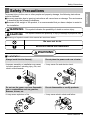
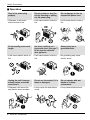
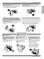
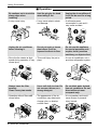
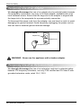
website http://www.lgservice.com
e-mail http://www.lgeservice.com/techsup.html
ACONDICIONADOR DE AIRE DE VENTANA
MANUAL DEL PROPIETARIO
Por favor lea las instrucciones de operación y las precauciones de
seguridad cuidadosa y totalmente antes de instalar y operar su
acondicionador de aire de ventana.
MODELS, MODELOS: LT0810C
LT1010C
LT1030C, LT1030H
LT1210C
LT1230C, LT1230H
ESPAÑOL
Please read the operating instructions and safety precautions carefully
and thoroughly before installing and operating your room air conditioner.
ENGLISH
ROOM AIR CONDITIONER
OWNER'S MANUAL
Window-Type Air Conditioner Owner’s Manual
TABLE OF CONTENTS
Safety Precautions..........................3
FOR YOUR RECORDS
Write the model and serial numbers here:
Before Operation .............................7
Model #
Serial #
Introduction ....................................8
Symbols Used in this Manual ........8
You con find the numbers on a label on the side of the
product.
Dealer's Name
Date Purchased
Electrical Safety ..............................8
Temporary Use of an
Adapter ........................................10
Temporary Use of an
Extension Cord ............................10
Operating Instructions .................11
Care and Mainenance ..................14
Installation ....................................15
Maintenance and Service ............22
Normal Operation .........................22
Troubleshooting ............................22
■ Staple your receipt to this page in the event you need it
to prove date of purchase or for warranty issues.
READ THIS MANUAL
Inside you will find many helpful hints on how to use and
maintain your air conditioner properly. Just a little preventive
care on your part can save you a great deal of time and
money over the life of your air conditioner.
You'll find many answers to common problems in the chart
of troubleshooting tips. If you review our chart of
Troubleshooting Tips first, you may not need to call for
service at all.
PRECAUTION
• Contact an Authorized Service Center for repair or
maintenance of this unit. Call 1-877-714-7486 to
locate the nearest ASC.
• The air conditioner is not intended for use by young
children or invalids without supervision.
• Young children should be supervised to ensure that
they do not play with the air conditioner.
• If the power cord requires replacement, have an
Authorized Servicer install an exact replacement
part.
• Installation work must be performed in accordance
with the National Electric Code by qualified and
authorized personnel only.
2 Room Air Conditioner
Safety Precautions
Safety Precautions
WARNING
This symbol indicates the possibility of death or serious injury.
CAUTION
This symbol indicates the possibility of injury or damage to properties only.
■ Meanings of symbols used in this manual are as shown below.
Be sure not to do.
Be sure to follow the instruction.
WARNING
■ Installation
Always install the trim frame(s).
• Improper assembly or installation may cause
incorrect operation, including injury, fire, and
electric shock hazards.
Do not use the power cord near flammable
gas or combustibles such as gasoline,
benzene, thinner, etc.
• It may cause explosion or fire.
Do not place the power cord near a heater.
• It may cause fire and electric shock.
Do not disassemble or modify products.
• It may cause electric shock and failure.
Gasolin
Owner’s Manual 3
ENGLISH
To prevent injury to the user or other people and property damage, the following instructions
must be followed.
■ Incorrect operation due to ignoring instructions will cause harm or damage. The seriousness
is classified by the following indications.
■ Because of the weight of the product, it is recommended that you have a helper to assist in
the installation.
Safety Precautions
■ Operation
Plug in the power plug
properly.
• Otherwise, it will cause
electric shock or fire.
Do not operate or stop the
unit by inserting or pulling
out the power plug.
Do not damage or use an
unspecified power cord.
• It will cause electric shock or
fire.
• It will cause electric shock or
fire.
ON
Do not modify power cord
length.
• It will cause electric shock or
fire.
Unplug the unit if strange
sounds, odors, or smoke
come from it.
• Otherwise it will cause fire
and electric shock accident.
4 Room Air Conditioner
Use the air conditioner on a
single outlet circuit. (See page 7.)
Do not share the outlet with
other appliances.
• It will cause electric shock or
fire.
Do not use the socket if it is
loose or damaged.
• It may cause fire and electric
shock.
Always plug into a
grounded outlet.
• No grounding may cause
electric shock.
Do not operate with wet
hands or in damp
environment.
• It may cause electric shock.
Safety Precautions
Close all doors, windows and other outside
openings to the room.
If water enters the product, turn off the the
power switch of the main body of appliance.
Contact service center after taking the powerplug out from the socket.
Do not clean the air conditioner with water.
• Water may enter the unit and degrade the
insulation. It may cause an electric shock.
CAUTION
■ Installation
Never touch the metal parts
of the unit when removing
the filter.
• They are sharp and may
cause injury.
Do not block the inlet or
outlet.
• It may cause failure of
appliance or performance
deteriorate.
Ensure that the outer case
is not damaged by age or
wear.
• If the outer case is damaged,
it must be repaired or
replaced immediately.
Leaving it damaged could
result in the air conditioner
falling out of the window,
creating a safety hazard.
Owner’s Manual 5
ENGLISH
• It may cause explosion, fire, and burn.
• The air conditioner must be operated in a
enclosed area to be most effective.
• It will cause electric shock or failure of
machine.
Ventilate before operating air conditioner
when gas goes out.
Safety Precautions
■ Operation
Be cautious not to touch the
sharp edges when
installing.
• It may cause injury.
Hold the plug by the head
when taking it out.
• It may cause electric shock
and damage.
Sharp
edges
Unplug the air conditioner
before cleaning it.
Do not put a pet or house
plant where it will be
exposed to direct air flow.
• Since the fan rotates at high
• This could injury the pet or
speed during operation, it may plant.
cause injury.
Always insert the filter
securely.
Clean it every two weeks.
• Operation without filters will
cause failure.
Use a soft cloth to clean. Do
not use wax, thinner, or a
strong detergent.
• The appearance of the air
conditioner may deteriorate,
change color, or develop
surface flaws.
x
Wa Thinner
6 Room Air Conditioner
Unplug the air conditioner if
it will not be used for a long
period.
• It will waste power
consumption in vain and it
may cause accident.
Do not use this appliance
for special purposes such
as pets, foods, precision
machinery, or objects of art.
• It is an air conditioner, not a
precision refrigeration system.
Do not drink water drained
from air conditioner. Do not
direct airflow at room
occupants only.
• It is not sanitary and could
cause illness or personal
injury hazard.
Before to Operation
Before Operation
1.
2.
3.
4.
5.
Plug in the power plug properly.
Use a dedicated circuit. Overloading the line could create a fire hazard.
Do not use an extension cord. See page 10 for more details.
Do not start/stop operation by plugging/unplugging the power cord.
If the power cord is damaged and requires replacement, have an Authorized
Servicer install an exact replacement part.
Usage
1. Being exposed to direct airflow for an extended period of time could be
hazardous to your health. Do not expose occupants, pets, or plants to direct
airflow for extended periods of time.
2. Due to the possibility of oxygen deficiency, ventilate the room when used
together with stoves or other heating devices.
3. Do not use this air conditioner for non-specified special purposes (e.g.
preserving precision devices, food, pets, plants, and art objects). Such usage
could damage the items.
4. The air conditioner is a consumer comfort appliance, not a precision climate
control system.
Cleaning and maintenance
1. Do not touch the metal parts of the unit when removing the filter. Injuries can
occur when handling sharp metal edges.
2. Do not use water to clean inside the air conditioner. Exposure to water can
destroy the insulation, leading to possible electric shock.
3. When cleaning the unit, first make sure that the power and breaker are turned
off. The fan rotates at a very high speed during operation. There is a
possibility of injury if the unit’s power is accidentally triggered on while
cleaning inner parts of the unit.
Service
For repair and maintenance, contact an Authorized Service Center. See the
warranty page for details or call (800) 243-0000. Have your model number and
serial number available. They should be written on page 2 of this manual.
Owner’s Manual 7
ENGLISH
Preparing for operation
Introduction
Introduction
Symbols Used in this Manual
This symbol alerts you to the risk of electric shock.
This symbol alerts you to hazards that could cause harm to the
air conditioner.
Tips
This symbol indicates special notes.
Electrical Safety
Electrical Data(For 115V model)
Line Cord Plug
Do not under any
circumstances cut
or remove the
grounding prong
from the plug.
Power supply cord with
3-prong grounding plug
Use Wall Receptacle
Parallel
type
Power Supply
Use 15 AMP time
delay fuse or 15 AMP
circuit breaker.
Standard 125V, 3-wire grounding
receptacle rated 15A, 125V AC
Electrical Data(For 230/208V model)
Line Cord Plug
Do not under any
circumstances cut
or remove the
grounding prong
from the plug.
Power supply cord with
3-prong grounding plug
Do not under any
circumstances cut
or remove the
grounding prong
from the plug.
Power supply cord with
3-prong grounding plug
8 Room Air Conditioner
Use Wall Receptacle
Tandem
type
Power Supply
Use 15 AMP
time delay fuse or
circuit breaker.
Standard 250V, 3-wire grounding
receptacle rated 15A, 250V AC
Perpendicular
type
Standard 250V, 3-wire grounding
receptacle rated 20A, 250V AC
Use 20 AMP
time delay fuse or
circuit breaker.
Refer to the nameplate
for correct fusing.
Electrical Safety
WARNING: This appliance must be properly grounded.
WARNING: Changing the outlet without making the appropriate wiring
changes will create an unsafe condition that could result in fire or
electrical shock. Refer all such work to a licensed and qualified
electrician.
Preferred method
Ensure proper ground
exists before use
WARNING: Do not cut or remove the grounding prong from the power
plug.
WARNING: Attaching the adapter ground terminal to the wall
receptacle cover screw does not ground the appliance unless the
cover screw is metal and not insulated, and the wall receptacle is
grounded through the house wiring.
WARNING: If you have any doubt whether the air conditioner is
properly grounded, have the wall receptacle and circuit checked by a
qualified electrician.
Owner’s Manual 9
ENGLISH
The power cord of this appliance is equipped with a three-prong grounding plug.
To minimize the risk of electric shock, use the plug with a standard three-slot
grounding wall power outlet. If the power outlet does not include a grounding slot,
have a qualified electrician replace the outlet before you use the room air
conditioner.
Electrical Safety
Temporary Use of an Adapter
We strongly discourage the use of an adapter due to potential safety hazards.
For temporary connections, use only a UL-listed adapter, available from most
local hardware stores. Ensure that the large slot in the adapter is aligned with
the large slot in the receptacle for a proper polarity connection.
To disconnect the power cord from the adapter, use one hand on each to avoid
damaging the ground terminal. Avoid frequently unplugging the power cord as
this can lead to eventual ground terminal damage.
Temporary method
Adapter Plug
Metal Screw
Receptacle Cover
WARNING: Never use the appliance with a broken adapter.
Temporary Use of an Extension Cord
We strongly discourage the use of an extension cord due to potential safety
hazards. For temporary situations, use only CSA certified and UL listed 3-wire
grounded extension cords, rated 15 A, 125 V.
10 Room Air Conditioner
Operating Instructions
Operating Instructions
Controls – Cooling Only
Operation
Off
Med
Fan
High
Cool
Low
Fan
Med
Cool
Off
Med Fan
Low Fan
High Cool
Med Cool
Low Cool
- Turns air conditioner off.
- Med speed fan operation without cooling.
- Low speed fan operation without cooling.
- Cooling with high speed fan operation.
- Cooling with med speed fan operation.
- Cooling with low speed fan operation.
Low Cool
Thermostat
4
5
Coo
ler
6
3
7
2
8
1
This automatically controls the temperature of the indoor air.
Turn the knob so that arrow points to the larger marks for
greater cooling. Point the arrow to the smaller marks for more
moderate cooling.
(i.e. the higher number, the greater cooling)
9
• FOR NORMAL COOLING
• ENERGY SAVER (optional)
1. Turn the Operation Knob to the High Cool from the
Low Cool setting.
2. Set the Thermostat control to the desired
temperature mark 5 (the mid-point is a good
starting position). If the room temperature is not
satisfactory after a reasonable time, adjust the
control to a cooler or warmer setting, as
appropriate.
On : Both the fan and the compressor turn on and
turn off together while operation knob is set to
the Cool position.
You can get the more economical operation.
• FOR MAXIMUM COOLING
1. Turn the Operation Knob to the High Cool setting.
2. Set the Thermostat control to the largest 9
temperature mark.
Off : The fan runs constantly while operation knob is
set to the Cool position.
Energy Saver
Off
On
You can access the Energy Saver switch when you
open the inlet grille.
• FOR QUIETER OPERATION
1. Turn the Operation Knob to the Low Cool setting.
2. Set the Thermostat control as needed.
Owner’s Manual 11
ENGLISH
The controls will look like one of the following:
Operating Instructions
The controls will look like one of the following:
Controls – Cooling & Heating
Operation
O
Thermostat
Warmer
Off
Fan
(
(
Low Cool
High Cool
Low Heat
High Heat
(
(
(
(
o
) :Turns the air conditioner off.
) : The low fan speed operation without cooling
(heating).
) : Cooling with the low speed fan operation.
) : Cooling with the high speed fan operation.
) : Heating with the low speed fan operation.
) : Heating with the high speed fan operation.
Turn the thermostat control to the desired setting. The central position
is a normal setting for average conditions. You can change this setting,
if necessary, in accordance with your temperature preference.
The thermostat automatically controls cooling or heating, but the fan
runs continuously whenever the air conditioner is in operation. If the
room is too warm, turn the thermostat control clockwise. If the room is
too cool, turn the thermostat control counterclockwise.
Cooler
• THE AIR CONDITIONER
• HEAT PUMP MODELS
This automatically controls the temperature of the
indoor air.
The compressor will turn on and off to keep the room
at the setting temperature.
In the heating operation, the electric heater will turn
on and off to keep the room at the setting
temperature.
When the outdoor temperature is lower than
-4°C (24°F), the electric heater will turn on instead of
the heat pump.
CAUTION: When the air conditioner
has been performed its cooling or
heating operation and is turned off or
set to the fan position, wait at least 3
minutes before resetting to the cooling
operation again.
12 Room Air Conditioner
A slight heat odor may come from the unit
when first switching to HEAT after the
cooling season is over. This odor, caused
by fine dust particles on the heater, will
disappear quickly. This is harmless.
Operating Instructions
Additional controls and important information.
ENGLISH
Ventilation
The ventilation lever is located in the right of the air discharge.
The ventilation lever must be in the CLOSE position in order to
maintain the best cooling conditions.
When fresh air is necessary in the room, set the ventilation lever to
the OPEN position.
The damper is opened and room air is exhausted outside.
PULL OPEN / PUSH CLOSE
Air Direction
The direction of air can be controlled wherever you want by
adjusting the horizontal louver and the vertical louver.
• HORIZONTAL AIR-DIRECTION CONTROL
The horizontal air direction is adjusted by moving vertical louver.
The lever of vertical louver is located in the right and left side of
the air discharge.
• VERTICAL AIR-DIRECTION CONTROL
The vertical air direction is adjusted by moving the horizontal
louver.
Owner’s Manual 13
Care and Maintenance
Care and Maintenance
TURN THE AIR CONDITIONER OFF AND REMOVE THE PLUG FROM THE POWER OUTLET.
Air Filter Cleaning
The air filter should be checked at least twice a month to see if cleaning is necessary.
Trapped particles in the filter will build up and block the airflow. This reduces the cooling
capacity and also causes an accumulation of frost on the cooling coils.
If the filter becomes turn or damaged you should replace
immediately. Replacement filters are available from your
salesperson, dealer, and the authorized customer service
centers.
1. Open the inlet grille downward by pulling out the top of the
inlet grille.
2. Remove the air filter from the front grille assembly by
pulling the air filter up slightly.
3. Wash the filter using lukewarm water below 40°C (104°F).
4. Gently shake the excess water from the filter completely.
Replace the filter.
How to Attach Front Grille to Cabinet
The front grille can be removed for cleaning or to check the model and serial numbers.
For your safety, you should attach the front grille as the following procedures.
1. Pull down front grille from the cabinet top.
2. Push front grille’s tips toward the cabinet in
order to insert front grille’s tabs into the
cabinet.
14 Room Air Conditioner
3. Open the inlet grille.
4. Tighten the screw through the front grille into
the plate of control box.
5. Close inlet grille.
Installation
Installation
INSTALLATION REQUIREMENTS
If you use an existing wall sleeve, you should
measure its dimensions.
Install the new air conditioner according to these
installation instructions to achieve the best
performance. All wall sleeves used to mount the
new air conditioner must be in good structural
condition and have a rear grille to securely attach
the new air conditioner. (FIG. 1)
With the LGE sleeve, you can maintain the best
performance of the new air conditioner. (FIG. 2)
19-21/32"
(499 mm)
24-21/32"
(626 mm)
14-13/32"
(366 mm)
18"(458 mm)
FIG. 1
Air Conditioner
25-7/8"
(656 mm)
15-17/32"
(394 mm)
Expanded
aluminum metal grille
16-23/32"
(425 mm)
LGE Wall Sleeve
FIG. 2
ELECTRICAL SERVICE
Check your available electrical service. The power
supply available must be the same as that shown
on the unit nameplate (found on left side of
cabinet).
All models are equipped with a 3-prong service
plug to provide proper service and safe positive
grounding. Do not change plug in any way. Do not
use an adapter plug. If your present wall outlet does
not match your plug, call a qualified electrician to
make the necessary corrections. SAVE CARTON
for storage and this OWNER'S MANUAL for future
reference. The carton is the best way to store unit
during winter or when not in use.
INSTALLATION HARDWARE
2
1
4
2 Size options
5
7
8
3
6
2 Size options
ITEM
1
2
3
4
5
6
7
8
NAME OF PARTS
Q'TY
PLASTIC GRILLE
1
HORIZONTAL INSULATION STRIPS
2
AROUND INSULATION STRIPS
2
SUPPORT BLOCK
2
BAFFLE
1
TRIM FRAME
2
SHIM
2
PLASTIC NUTS AND WASHER SCREWS 4
CAUTION: To avoid risk of personal
injury, property damage, or product
damage due to the weight of this device and
sharp edges that may be exposed:
• Air conditioners covered in this manual pose an
excessive weight hazard. Two or more people are
needed to move and install the unit.
To prevent injury or strain, use proper lifting and
carrying techniques when moving unit.
• Carefully inspect location where air conditioner will
be installed. Be sure it will support the weight of
the unit over an extended period of time.
• Handle air conditioner with care. Wear protective
gloves whenever lifting or carrying the unit. AVOID
the sharp metal fins of front and rear coils.
• Make sure air conditioner does not fall during
installation.
REQUIRED TOOLS:
• Tight Fitting gloves
• Standard screwdriver
• Phillips screwdriver
• Pliers
• Sharp knife
• 3/8-inch open end
wrench or adjustable
wrench
• 1/4-inch hex socket
and ratchet
• Tape measure
• Electric drill
• 1/4-inch drill bit
Owner’s Manual 15
ENGLISH
Remove packing sheet from the back of the sleeve, and
packing corner and blue tape from the air conditioner.
Installation
INSTALLATION
CAUTION: We strongly recommend
the removal of the old wall sleeve and
the installation of a new LGE Wall Sleeve.
If you decide to keep the existing wall sleeve,
you have to redirect the louvers at the back of the
wall sleeve illustration. The use of pliers is
recommended. If you DO NOT redirect, you run
the risk of poor performance or product failure.
This is not covered under the terms of the LGE
warranty.
• Pick a location which will allow the conditioned air
to blow into the area you want. Good installation
with special attention to the proper position of the
unit will lessen the chance that service will be
needed.
Tips
All wall sleeves used to mount the new
Air Conditioner must be in sound structural
condition and have a rear grille that securely
attaches to sleeve, or rear flange that serves as a
stop for the Air Conditioner,
2
Remove old air conditioner from existing wall
sleeve.
3
Clean the interior of an existing sleeve.
(Do not disturb seals.)
4
Wall sleeve must be securely fastened in wall
before installing the air conditioner. Use the
nails or screws through sleeve into wall, if
needed. Repaint sleeve if needed.
5
Prepare the wall sleeve for installation of the
unit. If you plan to use your existing wall
sleeve, and it is not LGE, use procedure B or
C below.
Procedure
A
ITEMS IN INSTALLATION HARDWARE
You may not need all parts in the kit. Discard
unused parts
ITEM (inches)
Qty.
Plastic grille
263/4 x 161/2
1
3
5
3
1
Horizontal Insulation Strips 13/8 x /83 x 27 /16
1 /8 x 1 /8 x 273/16 1
1
13/8 x 3/4 x 611/2
Around Insulation Strips
13/8 x 13/8 x 611/2
1
Support Block
13/4 x 13/8 x 45/16
2
Baffle
14 x 41/2 x 1/8
1
Shim
13 x 1 x 3/4
2
Trim Frame
2
Washer Screw
4
Nuts(Plastic)
4
HOW TO INSTALL
1 Identify the existing wall sleeve before
B
Brand
LGE
White-Westinghouse
Frigidaire Carrier
(52F series)
General Electric
/Hotpoint
Whirlpool
Carrier (51S series)
Fedders/Emerson
C
6
Emerson/Fedders
Friedrich
Fedders/Emerson
LGE
Emerson/Fedders
Carrier (51S Series)
Friedrich
16-7/8
17-1/8 or 23
18-5/8
16-3/4
or 19-3/4
15
16-3/4
CAUTION: When installation is
completed, replacement unit MUST have a
rearward slope as shown.
UNIT
Wall Sleeve
Wall Sleeve Dimensions (inches)
Width
Height
Depth
White-Westinghouse
Frigidaire
25-1/2
Carrier (52F series)
General Electric
26
/Hotpoint
Whirlpool
16, 17-1/2
or 22
Install new unit into wall sleeve.
installing the unit from the listed below.
Brand
Depth(inches)
16-23/32
15-1/4
16, 17-1/2
or 22
15-5/8
16-7/8
17-1/8
25-7/8 16-1/2
or 23
16-3/4
27
16-3/4
or 19-3/4
25-7/8 15-17/32 16-23/32
26-3/4 15-3/4
15
25-3/4 16-7/8
18-5/8
27
16-3/4
16-3/4
16 Room Air Conditioner
FRONT
1/4"
FIG. 3
Installation
PROCEDURE A
1
Install the new unit into the wall sleeve.
5
To assemble trim, snap the tab of each piece
into the slot of the other piece as shown below.
Slide trim over the front of the air conditioner
until trim is flush with sleeve as shown below.
FIG. 4
Trim (2 ea)
2
Fasten the 4 washer screws to secure the
grille to the wall sleeve. If you need plastic nuts
to mount plastic grille to the inside of the wall
sleeve, there are plastic nuts in the installation
kit. The nuts are installed from the inside of the
sleeve and are pressed into the square holes
of the rear flanges.
or
3
Wall
FIG. 7
FIG. 5
Remove the backing from the Horizontal
Insulation strip 13/8 x 3/8 x 273/16 and attach that
to the inside bottom of the sleeve as shown
below. Remove the backing from the Around
Insulation strip 13/8 x 3/4 x 611/2 and attach that
to the inside front of the sleeve as shown
below.
Around Insulation
Horizontal Insulation
CAUTION
• Air conditioners covered in this manual pose
an excessive weight hazard. Two or more
people are needed to move and install the unit.
To prevent injury or strain, use proper lifting
and carrying techniques when moving unit.
• When handling the air conditioner, be careful
to avoid cuts from sharp metal fins on front
and rear coils.
• Make sure air conditioner does not fall during
removal.
FIG. 6
Owner’s Manual 17
ENGLISH
If you are using the new sleeve supplied with
your unit, skip to step 3. Otherwise, install the
plastic grille from the kit. Cut the plastic grille
to 25-1/2" wide and 15-1/4" high. Place the
plastic grille to the inside of the wall sleeve at
the rear flange.
4
Installation
PROCEDURE B
1
4
Redirect the louvers at the back of the wall
sleeve to 60° angle as shown in the FIG 8. The
use of pliers is recommended.
7 5/16"
Remove the backing from the Horizontal
Insulation strip 13/8 x 5/8 x 273/16 and attach that
to the inside bottom of the sleeve as shown
below. Remove the backing from the Around
Insulation strip 13/8 x 3/4 x 611/2 and attach that
to the inside front of the sleeve as shown
below.
60°
60°
Rear Louvers
Around Insulation
(Top View)
Horizontal Insulation
FIG. 8
2
If the wall sleeve already has a rear grille, skip
to step 4. If the wall sleeve does not have a
rear grille or louvered panel, install the plastic
grille from the kit. Cut the plastic grille to 251/2" wide and 15-1/4" high. Place the plastic
grille to the inside of the wall sleeve at the rear
flange.
FIG. 11
5
If the depth of your existing wall sleeve is less
than or equal to 18", skip to step 7. Otherwise,
cut the baffles and the support blocks
according to length "A" in the table below.
Depth"D" of the existing Length "A"
wall sleeve (inches)
(inches)
D 18-5/8
18
18-5/8
3
6
Place the plastic grille
3
FIG. 9
Fasten the 4 washer screws to secure the
grille to the wall sleeve. If you need plastic nuts
to mount plastic grille to the inside of the wall
sleeve, there are plastic nuts in the installation
kit. The nuts are installed from the inside of the
sleeve and are pressed into the square holes
of the rear flanges.
Support
Block
3 4
/
D 19-3/4
19- /4 D
A
22
1-3/4
Baffle
4
FIG. 12
A
Remove the backing from the support blocks
and attach them to the inside of the wall sleeve
as shown FIG 9. Slide the baffle into slots of
the support blocks.
(7 5/16")
Wall
Baffle
Wall
Sleeve
Front
Support
Block
FIG. 13
or
Fasten the screws
18 Room Air Conditioner
FIG. 10
7
Install the new unit into the wall sleeve.
Installation
PROCEDURE B
8
ENGLISH
To assemble trim, snap the tab of each piece
into the slot of the other piece as shown below.
Slide trim over the front of the air conditioner
until trim is flush with sleeve as shown below.
Trim (2 ea)
Wall
FIG. 14
CAUTION
• Air conditioners covered in this manual pose
an excessive weight hazard. Two or more
people are needed to move and install the unit.
To prevent injury or strain, use proper lifting
and carrying techniques when moving unit.
• When handling the air conditioner, be careful
to avoid cuts from sharp metal fins on front
and rear coils.
• Make sure air conditioner does not fall during
removal.
Owner’s Manual 19
Installation
PROCEDURE C
1
4
Redirect the louvers at the back of the wall
sleeve to 60° angle as shown in the FIG 15.
The use of pliers is recommended.
7 13/16"
Remove the backing from the Horizontal
Insulation strip 13/8 x 13/8 x 273/16 and attach
that to the inside bottom of the sleeve as
shown below. Remove the backing from the
Around Insulation strip 13/8 x 13/8 x 611/2 and
attach that to the inside front of the sleeve as
shown below.
60°
60°
Rear Louvers
(Top View)
Around Insulation
Horizontal Insulation
FIG. 15
2
If the wall sleeve already has a rear grille, skip
to step 4. If the wall sleeve does not have a
rear grille or louvered panel, install the plastic
grille from the kit. Cut the plastic grille to 261/2" wide and 15-1/2" high. Place the plastic
grille to the inside of the wall sleeve at the rear
flange.
FIG. 18
5
If the depth of your existing sleeve is less than
or equal to 18”, skip to step 7. Otherwise, cut
the baffles and the support blocks according to
Length "A" in the table below.
Depth"D" of the existing Length "A"
wall sleeve (inches)
(inches)
18
18-5/8
D 18-5/8
/
1-3/4
4
22
Baffle
A
FIG. 19
FIG. 16
Place the plastic grille
3
Support
Block
3 4
D 19-3/4
19-3/4 D
A
Fasten the 4 washer screws to secure the
grille to the wall sleeve. If you need plastic nuts
to mount plastic grille to the inside of the wall
sleeve, there are plastic nuts in the installation
kit. The nuts are installed from the inside of the
sleeve and are pressed into the square holes
of the rear flanges.
6
Remove the backing from the support blocks
and attach them to the inside of the wall sleeve
as shown FIG 20. Slide the baffle into slots of
the support blocks
(7 13/16")
Wall
Baffle
Wall
Sleeve
Front
or
Fasten the screws
20 Room Air Conditioner
Support
Block
FIG. 20
FIG. 17
Installation
PROCEDURE C
7
9
1" high
3/
4"
High
FIG. 21
Trim (2 ea)
Shim (2EA)
Wall
6"
6"
FIG. 22
8
Install the new unit into the wall sleeve
FIG. 23
CAUTION
• Air conditioners covered in this manual pose
an excessive weight hazard. Two or more
people are needed to move and install the unit.
To prevent injury or strain, use proper lifting
and carrying techniques when moving unit.
• When handling the air conditioner, be careful
to avoid cuts from sharp metal fins on front
and rear coils.
• Make sure air conditioner does not fall during
removal.
Owner’s Manual 21
ENGLISH
Remove the backing from the 13" shim strips
and attach them as shown below in Fig. 22.
The higher portion of shim is to be placed in
front of the rib on the base of wall sleeve.
To assemble trim, snap the tab of each piece
into the slot of the other piece as shown below.
Slide trim over the front of the air conditioner
until trim is flush with sleeve as shown below.
Operating Instructions
Maintenance and Service
Troubleshooting Tips Save time and money!
Review the chart below first and you may not need to call for service.
Normal Operation
• You may hear a pinging noise caused by water being picked up and thrown against the condenser on rainy
days or when the humidity is high. This design feature helps remove moisture and improve efficiency.
• You may hear the thermostat click when the compressor cycles on and off.
• Water will collect in the base pan during high humidity or on rainy days. The water may overflow and drip from
the outdoor side of the unit.
• The fan may run even when the compressor does not.
Troubleshooting
Problem
Air conditioner
does not start
Air conditioner
does not cool as it
should
Air conditioner
freezing up
Possible Causes
What To Do
■ The air conditioner is
unplugged.
• Make sure the air conditioner plug is pushed
completely into the outlet.
■ The fuse is blown/circuit
breaker is tripped.
• Check the house fuse/circuit breaker box and
replace the fuse or reset the breaker.
■ Power failure.
• If power failure occurs, turn the mode control to
OFF.
When power is restored, wait 3 minutes to restart
the air conditioner to prevent tripping of the
■ Airflow is restricted.
• Make sure there are no curtains, blinds, or furniture
blocking the front of the air conditioner.
■ The THERMOSTAT may
not be set high enough.
• Turn the knob to a higher number. The highest
setting provides maximum cooling.
■ The air filter is dirty.
• Clean the filter at least every 2 weeks.
See the operating instructions section.
■ The room may have been
hot.
• When the air conditioner is first turned on,
you need to allow time for the room to cool down.
■ Cold air is escaping.
• Check for open furnace floor registers
and cold air returns.
• Set the air conditioner's vent to the closed position.
■ Cooling coils have iced up.
• See Air Conditioner Freezing Up below.
■ Ice blocks the air flow and
stops the air conditioner
from cooling the room.
• Set the mode control at Med Fan or High Cool with
the thermostat at 1 or 2.
22 Room Air Conditioner
Memo
ENGLISH
Owner’s Manual 23