1
website http://www.lgappliances.com
ENGLISH
LG
OWNER'S MANUAL
Please read the operating instructions and safety precautions carefully
and thoroughly before installing and operating your room air conditioner.
ACONDICIONADOR DE AIRE DE VENTANA
MANUAL DEL PROPIETARIO
Por favor lea las instrucciones de operación y las precauciones de
seguridad cuidadosa y totalmente antes de instalar y operar su
acondicionador de aire de ventana.
MODELS, MODELOS: LT1230CR
IMPORTANT
Please read through this manual. It contains valuable
information about your air conditioner.This manual may
help save time and money by explaining proper air
conditioner maintenance and preventing improper use.
PRECAUTIONS
Pay close attention to precautions in order to prevent
potential hazards and damage from misuse or improper
installation. LG is not responsible for any damages
caused by misuse of the air conditioner.
ESPAÑOL
LG
ROOM AIR CONDITIONER
Window-Type Air Conditioner Owner’s Manual
TABLE OF CONTENTS
Safety Precautions..........................3
FOR YOUR RECORDS
Write the model and serial numbers here:
Before Operation .............................7
Model #
Serial #
Introduction ....................................8
You can find them on a label on the side of each unit.
Dealer's Name
Electrical Safety ..............................9
Date Purchased
■ Staple your receipt to this page in the event you need it
to prove date of purchase or for warranty issues.
Installation ....................................11
Operating Instructions .................18
Maintenance and Service ............21
READ THIS MANUAL
Inside you will find many helpful hints on how to use and
maintain your air conditioner properly. Just a little preventive
care on your part can save you a great deal of time and
money over the life of your air conditioner.
You'll find many answers to common problems in the chart
of troubleshooting tips. If you review our chart of
Troubleshooting Tips first, you may not need to call for
service at all.
PRECAUTION
• Contact the authorized service technician for repair
or maintenance of this unit.
• Contact the installer for installation of this unit.
• The air conditioner is not intended for use by young
children or invalids without supervision.
• Young children should be supervised to ensure that
they do not play with the air conditioner.
• When the power cord is to be replaced, replacement
work shall be performed by authorized personnel only
using only genuine replacement parts.
• Installation work must be performed in accordance
with the National Electric Code by qualified and
authorized personnel only.
2 Room Air Conditioner
Safety Precautions
Safety Precautions
WARNING
This symbol indicates the possibility of death or serious injury.
CAUTION
This symbol indicates the possibility of injury or damage to properties only.
■ Meanings of symbols used in this manual are as shown below.
Be sure not to do.
Be sure to follow the instruction.
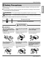
WARNING
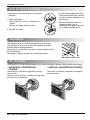
■ Installation
Don’t use a power cord, a
plug or a loose socket which
is damaged.
• Otherwise, it may cause a fire
or electrical shock.
Always plug into a grounded
outlet.
• Otherwise, it may cause a fire
or electrical shock.
Do not modify or extend the
power cord length.
• It will cause electric shock or fire
due to heat generation.
Do not disassemble or
modify products.
Be caution when unpacking
and installing.
Do not use the power cord near
flammable gas or combustibles
such as gasoline, benzene,
thinner, etc.
• It may cause failure and
electric shock.
• Sharp edges may cause
injury.
• It may cause explosion or fire.
Gasolin
Owner’s Manual 3
ENGLISH
To prevent injury to the user or other people and property damage, the following instructions
must be followed.
■ Incorrect operation due to ignoring instruction will cause harm or damage. The seriousness
is classified by the following indications.
Safety Precautions
■ Operation
Do not place heavy object
on the power cord and take
care so that the cord should
not be pressed.
Do not share the outlet with
other appliances.
• There is danger of fire or electric
shock.
• It will cause electric shock or fire
due to heat generation.
Do not place the power cord
near a heater.
• It may cause fire and electric
shock.
Do not allow water to run
into electric parts.
• It will cause failure of machine or
electric shock.
Take the power plug out if
necessary, holding the head
of the plug and do not touch
it with wet hands.
• Otherwise, it may cause a fire
or electrical shock.
Use a soft cloth to clean. Do
not use wax, thinner, or a
strong detergent.
• The appearance of the air
conditioner may deteriorate,
change color, or develop surface
flaws.
x
Wa Thinner
Unplug the unit if strange
sounds, odors, or smoke
come from it.
Do not open the suction
inlet grill of the product
during operation.
• Otherwise it may cause fire and
electric shock accident.
• Otherwise, it may electrical
shock and failure.
Ventilate the room well when
using this appliance
together with a stove, etc.
Turn off the power and
breaker firstly when
cleansing the unit.
• An oxygen shortage may occur. • Since the fan rotates at high
speed during operation, it may
cause injury.
4 Room Air Conditioner
If water enters the product, turn
off the the power switch of the
main body of appliance. Contact
service center after taking the
power-plug out from the socket.
Turn off the main power
switch when not using it for
a long time.
• Prevent accidental startup and
the possibility of injury.
Safety Precautions
Do not operate or stop the
unit by inserting or pulling
out the power plug.
Hold the plug by the head
when taking it out.
• It may cause electric shock and
damage.
• It will cause electric shock or fire.
When gas leaks, open the
window for ventilation
before operating the unit.
• Otherwise, it may cause
explosion, and a fire.
Do not operate with wet
hands or in damp
environment.
• It will cause electric shock.
Never touch the metal parts
of the unit when removing
the filter.
• They are sharp and may cause
injury.
CAUTION
■ Installation
Install the product so that the noise or hot
wind from the outdoor unit may not cause
any damage to the neighbors.
• Otherwise, it may cause dispute with the
neighbors.
Keep level parallel in installing the product.
• Otherwise, it may cause vibration or water
leakage.
Owner’s Manual 5
ENGLISH
• It will cause electric shock or fire
due to heat generation.
Do not damage or use an
unspecified power cord.
Safety Precautions
■ Operation
Do not put a pet or house
plant where it will be
exposed to direct air flow.
• It may cause injury.
Do not step on the
indoor/outdoor unit and do
not put anything on it.
• It may cause an injury through
dropping of the unit or falling
down.
Be cautious not to touch the
sharp edges when
installing.
• It may cause injury.
6 Room Air Conditioner
Do not block the inlet or
outlet of air flow.
Use a soft cloth to clean. Do
not use wax, thinner, or a
strong detergent.
• It may cause product failure.
• The appearance of the air
conditioner may deteriorate,
change color, or develop surface
flaws.
Always insert the filter
securely.
Clean it every two weeks.
• Operation without filters will
cause failure.
Avoid excessive cooling and
perform ventilation
sometimes.
• Otherwise, it may do harm to
your health.
Do not drink water drained
from air conditioner.
• It contains containments and will
make you sick.
Do not insert the hands or
bars through the air inlet or
outlet during operation.
• Otherwise, it may cause
personal injury.
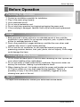
Before Operation
Before Operation
1.
2.
3.
4.
5.
6.
Contact an installation specialist for installation.
Plug in the power plug properly.
Use a dedicated circuit.
Do not use an extension cord.
Do not start/stop operation by plugging/unplugging the power cord.
If the cord/plug is damaged, replace it with only an authorized replacement
part.
Usage
1. Being exposed to direct airflow for an extended period of time could be
hazardous to your health. Do not expose occupants, pets, or plants to direct
airflow for extended periods of time.
2. Due to the possibility of oxygen deficiency, ventilate the room when used
together with stoves or other heating devices.
3. Do not use this air conditioner for non-specified special purposes (e.g.
preserving precision devices, food, pets, plants, and art objects). Such usage
could damage the items.
Cleaning and Maintenance
1. Do not touch the metal parts of the unit when removing the filter. Injuries can
occur when handling sharp metal edges.
2. Do not use water to clean inside the air conditioner. Exposure to water can
destroy the insulation, leading to possible electric shock.
3. When cleaning the unit, first make sure that the power and breaker are turned
off. The fan rotates at a very high speed during operation. There is a
possibility of injury if the unit’s power is accidentally triggered on while
cleaning inner parts of the unit.
Service
For repair and maintenance, contact your authorized service dealer.
Owner’s Manual 7
ENGLISH
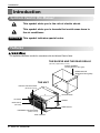
Preparing for Operation
Introduction
Introduction
Symbols Used in this Manual
This symbol alerts you to the risk of electric shock.
This symbol alerts you to hazards that could cause harm to
the air conditioner.
NOTICE
This symbol indicates special notes.
Features
This appliance should be installed in accordance with the National Electric Code.
THE SLEEVE AND THE REAR GRILLE
(optionally supplied with your unit)
SLEEVE ASSEMBLY
(Including Aluminum Rear grille)
REAR GRILLE
(Aluminum Rear grille)
THE UNIT
VERTICAL AIR DEFLECTOR
(Horizontal Louver)
AIR DISCHARGE
AIR FILTER
CABINET
INLET GRILLE
(Air Intake)
FRONT GRILLE
HORIZONTAL AIR DEFLECTOR
(Vertical Louver)
VENT CONTROL
8 Room Air Conditioner
Electrical Safety
Electrical Safety
115V~
230V~
Power cord may include a current
interrupter device. A test and reset button is
provided on the plug case. The device
should be tested on a periodic basis by first
pressing the TEST button and then the
RESET button. If the TEST button does not
trip or if the RESET button will not stay
engaged, discontinue use of the air
conditioner and contact a qualified service
technician.
NOTICE
The shape may be different according to its model.
Use Wall Receptacle
Standard 125V, 3-wire grounding
receptacle rated 15A, 125V AC
Power Supply
Use 15 AMP. time
delay fuse or 15 AMP.
circuit breaker.
Standard 250V, 3-wire grounding
receptacle rated 15A, 250V AC
Standard 250V, 3-wire grounding
receptacle rated 20A, 250V AC
Use 20 AMP. time
delay fuse or 20 AMP.
circuit breaker.
NOTICE
DO NOT USE AN EXTENSION CORD on 230,
208, and 230/208 Volt units.
All wiring should be made in accordance with local
electrical codes and regulations.
Aluminum house wiring may pose special
problems. Consult a qualified electrician.
Never push the test button during
operation
Otherwise this plug can damaged.
This device contains chemical, including
lead, known to the State of California to
cause cancer, and birth defects or other
reproductive harm.
Wash hands after handling.
Do not remove, modify or immerse this plug.
If this device trips, the cause it to be
corrected before further use.
The conductors inside this cord are
surrounded by shields, which monitor
leakage current.
These shields are not grounded.
<
Periodically examine the cord for any
damage. Do not use this product in the
event the shields become exposed.
Avoid shock hazard, this unit can not
be user serviced opening the tamper
resistant. Sealed portion of the unit
voids all warranties and performance
claims. This unit not intended for use
as an on-off switch.
Owner’s Manual 9
ENGLISH
Electrical Data
Electrical Safety
Electrical Safety
IMPORTANT
(PLEASE READ CAREFULLY)
FOR THE USER'S PERSONAL SAFETY, THIS
APPLIANCE MUST BE PROPERLY GROUNDED
The power cord of this appliance is equipped with a
three-prong (grounding) plug. Use this with a standard
three-slot (grounding) wall power outlet to minimize the
hazard of electric shock. The customer should have
the wall receptacle and circuit checked by a qualified
electrician to make sure the receptacle is properly
grounded.
DO NOT CUT OR REMOVE THE THIRD (GROUND)
PRONG FROM THE POWER PLUG.
A. SITUATIONS WHEN THE APPLIANCE WILL BE
DISCONNECTED OCCASIONALLY:
Because of potential safety hazards, we strongly
discourage the use of an adapter plug. However, if you
wish to use an adapter, a TEMPORARY
CONNECTION may be made. Use UL-listed adapter,
available from most local hardware stores.
The large slot in the adapter must be aligned with the
large slot in the receptacle to assure a proper polarity
connection.
: Attaching the adapter ground terminal to the wall
receptacle cover screw does not ground the
appliance unless the cover screw is metal, and not
insulated, and the wall receptacle is grounded
through the house wiring. The customer should
have the circuit checked by a qualified electrician to
make sure the receptacle is properly grounded.
Disconnect the power cord from the adapter, using
one hand on each. Otherwise, the adapter ground
terminal might break. DO NOT USE the appliance with
a broken adapter plug.
B. SITUATIONS WHEN THE APPLIANCE WILL BE
DISCONNECTED OFTEN.
Do not use an adapter plug in these situations.
Unplugging the power cord frequently can lead to an
eventual breakage of the ground terminal. The wall
power outlet should be replaced by a three-slot
(grounding) outlet instead.
USE OF EXTENSION CORDS
Because of potential safety hazards, we strongly
discourage the use of an extension cord. However, if
you wish to use an extension cord, use a CSA
certified/UL-listed 3-wire (grounding) extension cord,
rated at 15A, 125V.
10 Room Air Conditioner
Installation
Installation
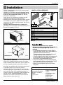
INSTALLATION REQUIREMENTS
If you use an existing wall sleeve, you should
measure its dimensions.
Install the new air conditioner according to these
installation instructions to achieve the best
performance. All wall sleeves used to mount the new
air conditioner must be in good structural condition
and have a rear grille to securely attach the new air
conditioner. (FIG. 1)
With the LGE sleeve(optionally supplied with
your unit), you can maintain the best performance of
the new air conditioner. (FIG. 2)
24"(610 mm)
14-13/32"
(366 mm)
18-15/32"(468 mm)
Air Conditioner
2
1
4
5
2 Size options
6
8
9
10
3
7
2 Size options
NAME OF PARTS
Q'TY
PLASTIC GRILLE
1
VERTICAL INSULATION STRIP
1
AROUND INSULATION STRIPS
2
HORIZONTAL INSULATION STRIP
1
SUPPORT BLOCK
2
BAFFLE
1
TRIM FRAME
2
SHIM
2
PLASTIC NUTS AND WASHER SCREWS 4
FIG. 1
25-7/8"
(656 mm)
15-17/32"
(394 mm)
Aluminum metal grille
16-23/32"
(425 mm)
LGE Wall Sleeve
INSTALLATION HARDWARE
ITEM
1
2
3
4
5
6
7
8
9
20-3/32"
(511 mm)
ENGLISH
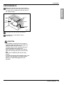
Remove packing materials from the wall sleeve and tape
from the air conditioner.
FIG. 2
ELECTRICAL SERVICE
Check your available electrical service. The power
supply available must be the same as that shown on
the unit nameplate (found on left side of cabinet).
All models are equipped with a 3-prong service plug
to provide proper service and safe positive
grounding. Do not change plug in any way. Do not
use an adapter plug. If your present wall outlet does
not match your plug, call a qualified electrician to
make the necessary corrections. SAVE CARTON for
storage and this OWNER'S MANUAL for future
reference. The carton is the best way to store unit
during winter or when not in use.
To avoid risk of personal injury, property
damage, or product damage due to the weight of
this device and sharp edges that may be
exposed:
• Air conditioners covered in this manual pose an
excessive weight hazard. Two or more people are
needed to move and install the unit.
To prevent injury or strain, use proper lifting and
carrying techniques when moving unit.
• Carefully inspect location where air conditioner will
be installed. Be sure it will support the weight of
the unit over an extended period of time.
• Handle air conditioner with care. Wear protective
gloves whenever lifting or carrying the unit. AVOID
the sharp metal fins of front and rear coils.
• Make sure air conditioner does not fall during
installation.
REQUIRED TOOLS:
• Tight Fitting gloves
• Standard screwdriver
• Phillips screwdriver
• Pliers
• Sharp knife
• 3/8-inch open end
wrench or adjustable
wrench
• 1/4-inch hex socket
and ratchet
• Tape measure
• Electric drill
• 1/4-inch drill bit
Owner’s Manual 11
Installation
INSTALLATION
NOTICE
We strongly recommend the removal of the
old wall sleeve and the installation of a new
LGE Wall Sleeve.
If you decide to keep the existing wall sleeve,
you have to redirect the louvers at the back of
the wall sleeve illustration. The use of pliers is
recommended. If you DO NOT redirect, you
run the risk of poor performance or product
failure. This is not covered under the terms of
the LGE warranty.
• Pick a location which will allow the conditioned air
to blow into the area you want. Good installation
with special attention to the proper position of the
unit will lessen the chance that service will be
needed.
ITEMS IN INSTALLATION HARDWARE
All wall sleeves used to mount the new Air
Conditioner must be in sound structural condition
and have a rear grille that securely attaches to
sleeve, or rear flange that serves as a stop for the
Air Conditioner.
2 Remove old air conditioner from existing wall
sleeve.
3
Clean the interior of an existing sleeve.
(Do not disturb seals.)
4
Wall sleeve must be securely fastened in wall
before installing the air conditioner. Use the
nails or screws through sleeve into wall, if
needed. Repaint sleeve if needed.
5
Prepare the wall sleeve for installation of the
unit. If you plan to use your existing wall sleeve,
and it is not LGE, use procedure B or C below.
Procedure
A
You may not need all parts in the kit. Discard unused
parts
ITEM (inches)
Qty.
Plastic grille
263/4 x 161/2
1
Vertical insulation strip
159/16 x 13/8 x 13/8 1
671/8 x 13/8 x 25/32 1
Around Insulation Strips
5927/32 x 13/8 x 13/8 1
Horizontal Insulation Strip 237/32 x 13/8 x 13/16 1
Support Block
13/4 x 13/8 x 45/16
2
Baffle
14 x 41/2 x 1/8
1
Shim
1113/16 x 1 x 3/4
2
Trim Frame
2
Washer Screw
4
Nuts(Plastic)
4
Grille Rear
1
HOW TO INSTALL
the existing wall sleeve before installing
1 Identify
the unit from the listed below.
Brand
Wall Sleeve Dimensions (inches)
Width
Height
Depth
White-Westinghouse
Frigidaire
25-1/2
Carrier (52F series)
General Electric
26
/Hotpoint
Whirlpool
Fedders/Emerson
LGE
Emerson/Fedders
Carrier (51S Series)
Friedrich
15-1/4
16, 17-1/2
or 22
15-5/8
16-7/8
Depth(inches)
16-23/32
16, 17-1/2
or 22
16-7/8
17-1/8 or 23
18-5/8
16-3/4
or 19-3/4
15
16-3/4
Fedders/Emerson
C
6
Emerson/Fedders
Friedrich
Install new unit into wall sleeve.
When installation is completed, replacement unit
MUST have a rearward slope as shown. To
achieve 1/4" slope, remove the backing from the
11-13/16" shim strips and attach them as shown
below in Fig. 3. Place the higher portion of shim to
the front of the rib on base of wall sleeve.
1" high
3/4" High
UNIT
17-1/8
or 23
16-3/4
27
16-3/4
or 19-3/4
25-7/8 15-17/32 16-23/32
26-3/4 15-3/4
15
25-3/4 16-7/8
18-5/8
27
16-3/4
16-3/4
25-7/8
B
Brand
LGE
White-Westinghouse
Frigidaire Carrier
(52F series)
General Electric
/Hotpoint
Whirlpool
Carrier (51S series)
Wall Sleeve
16-1/2
FRONT
Shim
6"
6"
SHIM PLACEMENT
1/4"
UNIT INSTALLATION
FIG. 3
12 Room Air Conditioner
Installation
PROCEDURE A
1
FIG. 4
2
Fasten the 4 washer screws to secure the grille
to the wall sleeve. If you need plastic nuts to
mount plastic grille to the inside of the wall
sleeve, there are plastic nuts in the installation
kit. The nuts are installed from the inside of the
sleeve and are pressing into the square holes
of the rear flanges.
4
Install the new unit into the wall sleeve.
5
To assemble trim, snap the tab of each piece
into the slot of the other piece as shown below.
Slide trim over the front of the air conditioner
until trim is flush with sleeve as shown below.
Trim (2 ea)
Wall
FIG. 7
or
3
FIG. 5
Remove the backing from the Vertical Insulation
strip 159/16 x 13/8 x 13/8 and attach that to the
inside right of the sleeve as shown below.
Remove the backing from the Around Insulation
strip 671/8 x 13/8 x 25/32 and attach that to the
inside front of the sleeve as shown below.
Indoor
Outdoor
Around Insulation
Vertical Insulation
9 1/2"
• Air conditioners covered in this manual pose an
excessive weight hazard. Two or more people are
needed to move and install the unit.
To prevent injury or strain, use proper lifting and
carrying techniques when moving unit.
• When handling the air conditioner, be careful to
avoid cuts from sharp metal fins on front and rear
coils.
• Make sure air conditioner does not fall during
removal.
• If unit does not operate after installation check, to
be sure the circuit interrupter has not been tripped.
Refer to the Troubleshooting guide for reset
procedure.
6"
FIG. 6
Owner’s Manual 13
ENGLISH
If you are using the new sleeve (optionally
supplied with your unit),skip to step 3.
Otherwise, install the plastic grille from the kit.
Cut the plastic grille to 25-1/2" wide and 151/4" high. Place the plastic grille to the inside
of the wall sleeve at the rear flange.
Installation
PROCEDURE B
1
4
Redirect the louvers at the back of the wall
sleeve to 60° angle as shown in the FIG 8. The
use of pliers is recommended.
Remove the backing from the Vertical Insulation
strip 159/16 x 13/8 x 13/8 and attach that to the
inside right of the sleeve as shown below.
Remove the backing from the Around Insulation
strip 671/8 x 13/8 x 25/32 and attach that to the
inside front of the sleeve as shown below.
7 3/32"
Indoor
60°
60°
Outdoor
Rear Louvers
Around Insulation
(Top View)
Vertical Insulation
FIG. 8
2
Place the plastic grille
3
9 1/2"
6"
FIG. 11
If the wall sleeve already has a rear grille, skip
to step 4. If the wall sleeve does not have a rear
grille or louvered panel, install the plastic grille
from the kit. Cut the plastic grille to 25-1/2" wide
and 15-1/4" high. Place the plastic grille to the
inside of the wall sleeve at the rear flange.
FIG. 9
Fasten the 4 washer screws to secure the grille
to the wall sleeve. If you need plastic nuts to
mount plastic grille to the inside of the wall
sleeve, there are plastic nuts in the installation
kit. The nuts are installed from the inside of the
sleeve and are pressed into the square holes of
the rear flanges.
5
If the depth of your existing wall sleeve is less
than or equal to 18", skip to step 6. Otherwise,
cut the baffles and the support blocks according
to length "A" in the table below.
Depth"D" of the existing Length "A"
wall sleeve (inches)
(inches)
18
18-5/8
D 18-5/8
D 19-3/4
19-3/4 D
or
Fasten the screws
14 Room Air Conditioner
FIG. 10
22
A
Support
Block
3 4
/
1-3/4
4
Baffle
A
FIG. 12
Installation
PROCEDURE B
6
ENGLISH
Remove the backing from the support blocks
and attach them to the inside of the wall sleeve
as shown FIG 13. Slide the baffle into slots of
the support blocks.
(7 3/32")
Wall
Wall
Sleeve
Baffle
Front
Support
Block
FIG. 13
7
Install the new unit into the wall sleeve.
8
Assemble trim as described in Step 5,
Procedure A.
CAUTION
• Air conditioners covered in this manual pose an
excessive weight hazard. Two or more people are
needed to move and install the unit.
To prevent injury or strain, use proper lifting and
carrying techniques when moving unit.
• When handling the air conditioner, be careful to
avoid cuts from sharp metal fins on front and rear
coils.
• Make sure air conditioner does not fall during
removal.
• If unit does not operate after installation check, to be
sure the circuit interrupter has not been tripped.
Refer to the Troubleshooting guide for reset
procedure.
Owner’s Manual 15
Installation
PROCEDURE C
1
4
Redirect the louvers at the back of the wall
sleeve to 60° angle as shown in the FIG 14.
The use of pliers is recommended.
7 3/32"
Remove the backing from the Horizontal
Insulation strip 237/32 x 13/8 x 13/16 and attach
that to the inside right of the sleeve as shown
below. Remove the backing from the Around
Insulation strip 5927/32 x 13/8 x 13/8 and attach
that to the inside front of the sleeve as shown
below.
60°
60°
Rear Louvers
Indoor
Outdoor
(Top View)
Around Insulation
Horizontal Insulation
FIG. 14
2
If the wall sleeve already has a rear grille, skip
to step 4. If the wall sleeve does not have a rear
grille or louvered panel, install the plastic grille
from the kit. Cut the plastic grille to 26-1/2" wide
and 15-1/2" high. Place the plastic grille to the
inside of the wall sleeve at the rear flange.
8 1/2"
FIG. 17
5
If the depth of your existing sleeve is less than
or equal to 18”, skip to step 7. Otherwise, cut
the baffles and the support blocks according to
Length "A" in the table below.
Depth"D" of the existing Length "A"
wall sleeve (inches)
(inches)
18
18-5/8
D 18-5/8
/
1-3/4
4
22
Baffle
A
FIG. 18
FIG. 15
Place the plastic grille
3
Support
Block
3 4
D 19-3/4
19-3/4 D
A
Fasten the 4 washer screws to secure the grille
to the wall sleeve. If you need plastic nuts to
mount plastic grille to the inside of the wall
sleeve, there are plastic nuts in the installation
kit. The nuts are installed from the inside of the
sleeve and are pressed into the square holes of
the rear flanges.
6
Remove the backing from the support blocks
and attach them to the inside of the wall sleeve
as shown FIG 19. Slide the baffle into slots of
the support blocks
(7 3/32")
Wall
Wall
Sleeve
Baffle
Front
FIG. 19
or
Fasten the screws
16 Room Air Conditioner
Support
Block
FIG. 16
Installation
PROCEDURE C
7
1" high
3/ "
4
High
FIG. 20
• Air conditioners covered in this manual pose an
excessive weight hazard. Two or more people are
needed to move and install the unit.
To prevent injury or strain, use proper lifting and
carrying techniques when moving unit.
• When handling the air conditioner, be careful to avoid
cuts from sharp metal fins on front and rear coils.
• Make sure air conditioner does not fall during
removal.
• If unit does not operate after installation check, to be
sure the circuit interrupter has not been tripped.
Refer to the Troubleshooting guide for reset
procedure.
Shim (2EA)
6"
6"
FIG. 21
8
Install the new unit into the wall sleeve
9
Assemble trim as described in Step 6,
Procedure A.
Owner’s Manual 17
ENGLISH
To achieve rearward slope for unit draining,
remove the backing from the 1113/16" shim
strips and attach them as shown below in Fig.
21. The higher portion of shim is to be placed
in front of the rib on the base of wall sleeve.
Operating Instructions
Operating Instructions
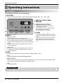
Controls
The controls will look like one of the following.
FAN SPEED
• Every time you push this button, it advances the setting as follows: {High → Low → Med → High}
Cool
F1 LOW
F2 MED
F3 HIGH
Energy
Saver
'F
TEMPERATURE SETTING
Fan
Timer
MODE
TIMER
TEMP
FAN
SPEED
REMOTE CONTROL SIGNAL
RECEIVER
POWER
• Use this button to automatically control the
temperature of the room.
The temperature can be set within a range of
60°F to 86°F by increments of 1°F.
• The setting appears in the display.
POWER
TIMER
- SHUT-OFF TIME
• You will usually use shut-off time while you sleep.
• If unit is running, use Timer to set number of hours until shut-off.
• For your sleeping comfort, once Time is set, the Temperature
setting will raise 2°F after 30 min., and once again after another
30 min.
• Push Timer button to advance setting from 1Hour → 2Hours → ...
→ 12Hours maximum.
• To turn the air conditioner ON, push this button.
To turn the air conditioner OFF, push the button
again.
• This button takes priority over any other button.
• When you first turn it on, the unit is in cool
mode, High fan speed, Temperature setting at
72°F.
- START TIME
• If unit is off, use Timer to set number of hours before unit starts.
• Push Timer button to advance setting from 1Hour → 2Hours → ...
→ 12Hours maximum.
MODE
- Push this button to shift mode of operation from COOL → ENERGY SAVER → FAN.
- COOL:
• Fan runs continually for normal cooling operation.
- ENERGY SAVER:
• The fan stops when the compressor stops cooling. Approximately every 3 minutes the fan will turn on and the unit will
check the room air temperature to determine if cooling is needed.
- FAN:
• Fan-only operation.
AUTO RESTART
When power is restored after an electrical power failure, the unit will begin to run at its last setting.
18 Room Air Conditioner
Operating Instructions
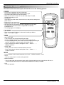
Remote control
The remote control and control panel will look like one of the following pictures.
• To turn the air conditioner ON, push this button.
To turn the air conditioner OFF, push the button again.
• This button takes priority over any other button.
• When you first turn it on, the unit is in cool mode, High fan speed,
Temperature setting at 72°F.
• Auto Restart
In the event at a power failure, the unit will run at the previous setting once
power returns.
Power
Temp
TEMPERATURE SETTING
• Use this button to automatically control the temperature of the room.
The temperature can be set within a range of 60°F to 86°F by
increments of 1°F.
• The setting appears in the display.
FAN SPEED
Fan Speed
Timer
Mode
• Every time you push this button it advances the setting as follows:
(High → Low → Med → High)
TIMER
- SHUT-OFF TIME
• You will usually use shut-off time while you sleep.
• If unit is running, use Timer to set number of hours until shut-off.
• For your sleeping comfort, once Time is set, the Temperature setting will
raise 2°F after 30 min, and once again after another 30 min.
• Push Timer button to advance setting from 1Hour → 2Hours → ... →
12Hours maximum.
- START TIME
• If unit is off, use Timer to set of hours before unit starts.
• Push Timer button to advance setting from 1Hour → 2Hours → ... →
12Hours maximum.
MODE
- Push this button to shift mode of operation from COOL → ENERGY SAVER → FAN.
- COOL:
• Fan runs continually for normal cooling operation.
- ENERGY SAVER:
• The fan stops when the compressor stops cooling. Approximately every 3 minutes the fan will turn on
and the unit will check the room air temperature to determine if cooling is needed.
- FAN:
• Fan-only operation.
Owner’s Manual 19
ENGLISH
POWER
Operating Instructions
How to insert Batteries
1. Remove the cover from the back of the remote
controller.
• Do not use rechargeable batteries.
Such batteries differ from standard
dry cells in shape, dimensions, and
performance.
2. Insert two batteries.
• Be sure that the (+) and (-) directions are
correct.
• Be sure that both batteries are new.
• Remove the batteries from the
remote controller if the air
conditioner is not going to be used
for an extended length of time.
3. Re-attach the cover.
Ventilation
The ventilation lever is located in the right of the air discharge.
The ventilation lever must be in the CLOSE position in order to
maintain the best cooling conditions.
When fresh air is necessary in the room, set the ventilation lever to
the OPEN position.
The damper is opened and room air is exhausted outside.
PULL OPEN / PUSH CLOSE
Air Direction
The direction of air can be controlled wherever you want by adjusting the horizontal louver and the vertical louver.
• HORIZONTAL AIR-DIRECTION
CONTROL
• VERTICAL AIR-DIRECTION CONTROL
The horizontal air direction is adjusted by moving
vertical louver.
The lever of vertical louver is located in the right and
left side of the air discharge.
The vertical air direction is adjusted by moving the
horizontal louver.
20 Room Air Conditioner
Maintenance and Service
Maintenance and Service
Air Filter Cleaning
The air filter should be checked at least twice a month to see if cleaning is necessary.
Trapped particles in the filter will build up and block the airflow. This reduces the cooling
capacity and also causes an accumulation of frost on the cooling coils.
If the filter becomes turn or damaged you should replace
immediately. Replacement filters are available from your
salesperson, dealer, and the authorized customer service
centers.
1. Open the inlet grille downward by pulling out the top of the
inlet grille.
2. Remove the air filter from the front grille assembly by
pulling the air filter up slightly.
3. Wash the filter using lukewarm water below 40°C (104°F).
4. Gently shake the excess water from the filter completely.
Replace the filter.
How to Attach Front Grille to Cabinet
The front grille can be removed for cleaning or to check the model and serial numbers.
For your safety, you should attach the front grille as the following procedures.
1. Pull down front grille from the cabinet top.
2. Push front grille’s tips toward the cabinet in
order to insert front grille’s tabs into the
cabinet.
Cool
F1 LOW
F2 MED
F3 HIGH
Energy
Saver
3. Open the inlet grille.
4. Tighten the screw through the front grille into
the plate of control box.
5. Close inlet grille.
'F
Fan
Timer
MODE
TIMER
TEMP
FAN
SPEED
POWER
Owner’s Manual 21
ENGLISH
TURN THE AIR CONDITIONER OFF AND REMOVE THE PLUG FROM THE POWER OUTLET.
Maintenance and Service
Common Problems and Solutions
Troubleshooting Tips Save time and money!
Review the chart below first and you may not need to call for service.
Normal Operation
• You may hear a pinging noise caused by water being picked up and thrown against the condenser on rainy
days or when the humidity is high. This design feature helps remove moisture and improve efficiency.
• You may hear the thermostat click when the compressor cycles on and off.
• Water will collect in the base pan during high humidity or on rainy days. The water may overflow and drip from
the outdoor side of the unit.
• The fan may run even when the compressor does not.
Troubleshooting
Problem
Air conditioner
does not start
Possible Causes
■ The air conditioner is
unplugged.
• Make sure the air conditioner plug is pushed
completely into the outlet.
■ The fuse is blown/circuit
breaker is tripped.
• Check the house fuse/circuit breaker box and replace
the fuse or reset the breaker.
■ Power failure.
• If power failure occurs, turn the mode control to OFF.
When power is restored, wait 3 minutes to restart the
air conditioner to prevent tripping of the compressor
overload.
■ The current interrupter
device is tripped.
• Press the RESET button located on the power cord
plug. If the RESET button will not stay engaged,
discontinue use of the air conditioner and contact a
qualified service technician.
• Make sure there are no curtains, blinds, or furniture
blocking the front of the air conditioner.
■ Airflow is restricted.
Air conditioner
does not cool as it
should
Air conditioner
freezing up
What To Do
■ TEMP Control set too
higher number.
• Set the TEMP control to a lower number.
■ The air filter is dirty.
• Clean the filter at least every 2 weeks.
See the operating instructions section.
■ The room may have been
hot.
• When the air conditioner is first turned on,
you need to allow time for the room to cool down.
■ Cold air is escaping.
• Check for open furnace floor registers
and cold air returns.
• Set the air conditioner's vent to the closed position.
■ Cooling coils have iced up.
• See Air Conditioner Freezing Up below.
■ Ice blocks the air flow and
stops the air conditioner
from cooling the room.
• Set the mode control at High Fan or High Cool with
the high temperature.
22 Room Air Conditioner
Memo
ENGLISH
Owner’s Manual 23