1
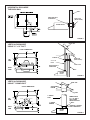
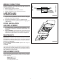
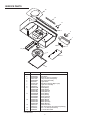
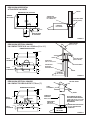
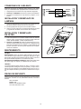
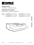
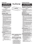
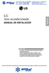
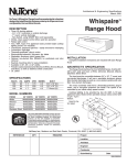
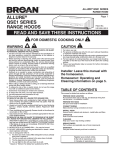
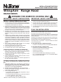
INSTALLATION INSTRUCTIONS
READ & SAVE THESE INSTRUCTIONS!
WhispAire™ Range Hood
WA6500 SERIES
!
INTENDED FOR DOMESTIC COOKING ONLY
!
IMPORTANT SAFETY INSTRUCTIONS
IMPORTANT SAFETY INSTRUCTIONS
WARNING – TO REDUCE THE RISK OF FIRE, ELECTRIC SHOCK,
OR INJURY TO PERSONS, OBSERVE THE FOLLOWING:
1. Use this unit only in the manner intended by the manufacturer.
If you have questions, contact the manufacturer at the address
or telephone number listed in the warranty.
2. Before servicing or cleaning unit, switch power off at service
panel and lock service panel to prevent power from being
switched on accidentally. When the service disconnecting
means cannot be locked, securely fasten a prominent warning device, such as a tag, to the service panel.
3. Installation work and electrical wiring must be done by a qualified person(s) in accordance with all applicable codes and
standards, including fire-rated construction codes and standards.
4. Sufficient air is needed for proper combustion and exhausting
of gases through the flue (chimney) of fuel burning equipment
to prevent backdrafting. Follow the heating equipment
manufacturer's guideline and safety standards such as those
published by the National Fire Protection Association (NFPA),
and the American Society for Heating, Refrigeration and Air
Conditioning Engineers (ASHRAE), and the local code authorities.
5. When cutting or drilling into wall or ceiling, do not damage
electrical wiring and other hidden utilities.
6. Ducted fans must always be vented to the outdoors.
7. Use with approved cord-connection kit only.
8. To reduce the risk of fire, use only metal ductwork.
1. For general ventilating use only. Do not use to exhaust hazardous or explosive materials and vapors.
2. To reduce the risk of fire or electrical shock, this range hood
should not be used with an additional speed control device.
3. To reduce the risk of shock, disconnect power before servicing.
4. To reduce the risk of fire and to properly exhaust air, be sure to
duct air outside.
TO REDUCE THE RISK OF A RANGE TOP GREASE FIRE:
1. Never leave surface units unattended at high settings.
Boilovers cause smoking and greasy spillovers that may ignite. Heat oils slowly on low or medium settings.
2. Always turn hood ON when cooking at high heat or when
cooking flaming foods.
3. Clean ventilating fans frequently. Grease should not be allowed to accumulate on fan or filter.
4. Use proper pan size. Always use cookware appropriate for
the size of the surface element.
TO REDUCE THE RISK OF INJURY TO PERSONS IN THE EVENT
OF A RANGE TOP GREASE FIRE, OBSERVE THE FOLLOWING*:
1. SMOTHER FLAMES with a close-fitting lid, cookie sheet, or
metal tray, then turn off the burner. BE CAREFUL TO PREVENT BURNS. If the flames do not go out immediately, EVACUATE AND CALL THE FIRE DEPARTMENT.
2. NEVER PICK UP A FLAMING PAN - You may be burned.
3. DO NOT USE WATER, including wet dishcloths or towels - a
violent steam explosion will result.
4. Use an extinguisher ONLY if:
A. You know you have a Class ABC extinguisher, and you
already know how to operate it.
B. The fire is small and contained in the area where it started.
C. The fire department is being called.
D. You can fight the fire with your back to an exit.
* Based on “Kitchen Firesafety Tips” published by NFPA.
PLAN THE INSTALLATION
Recommended mounting height is 18” to 24” from the bottom of
the range hood to the top of the cooking surface.
The hood should be mounted to the bottom of a standard wall
cabinet. If the hood must be mounted directly to a wall, secure the
hood to wall studs.
All wiring must comply with local codes and the unit must be properly grounded. The hood is connected to a 110-120vAC lighting
circuit (15 amp) in the circuit breaker or fuse box.
This range hood is “Convertible” – it may be installed as a ducted
or as a non-ducted unit.
IF THE RANGE HOOD IS TO BE NON-DUCTED:
• Purchase non-ducted (duct-free) charcoal filter Model BPQTF.
IF THE RANGE HOOD IS TO BE DUCTED:
• Ductwork can be installed vertically or horizontally.
• Duct runs should be as short as possible.
• Avoid the use of elbows.
• Use duct tape at all joints.
• Do not use duct smaller than the discharge on the hood.
• For 7” round ductwork installation, use 7” round damper, Model
895 (purchased separately).
HORIZONTAL DISCHARGE
THROUGH WALL
WALL
SUPPLIED DUCT
TRANSITION
WALL CAP
(Model 838AL)
RANGE HOOD
FIGURE 1
ROOF CAP
VERTICAL DISCHARGE
USING 3¼” x 10” DUCT
CUTOUT DIMENSIONS
CL
1"
ELBOW
TOP
VIEW
EAVE CAP
(Model 836AL)
1
12"
3¼" x 10"
DUCT
9"
31/4" x 10"
2"
3/4"
BACK
VIEW
ELEC. K.O.
3/8"
31/4" x 10"
WALL CAP
SUPPLIED DUCT
TRANSITION
1"
CL
WALL
6"
RANGE
HOOD
FIGURE 2
VERTICAL DISCHARGE
USING 7” ROUND DUCT
ROOF CAP
CUTOUT DIMENSIONS
ADJUSTABLE
ELBOW
1"
CL
ROOF
TOP
VIEW
7" ROUND
DUCT
1
12"
9"
5"
2"
3/4"
BACK
VIEW
REMOVE BOTH
3¼" x 10" AND 7"
HALF ROUND
KNOCKOUTS FOR
7" DUCT
7" DIA
ELEC. K.O.
CL
7" ROUND
DAMPER
7/8"
SUPPLIED 7" ROUND
DUCT TRANSITION
RANGE
HOOD
6"
FIGURE 3
2
PREPARATION
LOCATORS
1. Use the dimensional drawings (Refer to FIGURES 1 - 3) to lay
out the range hood’s mounting holes, wiring access and
ductwork by marking the cabinet bottom and drywall where
applicable.
2. Make cutouts for wiring and ductwork.
3. If the hood is to be ducted, install the ductwork so that is flush
to the range hood’s mounting surface.
• Refer to FIGURE 1 if the range hood is to be installed with a
horizontal discharge.
• Refer to FIGURE 2 and FIGURE 3 if the range hood is to be
installed with a vertical discharge.
4. Run two-conductor wire (with ground) from a power source to
the hood location. Bring approximately 12” of wiring through
wiring hole in cabinet.
5. Drill four 3/32” diameter pilot holes at points where mounting
holes are marked in cabinet bottom.
6. Insert four (4) mounting screws, leaving approximately ¼” of
thread exposed.
7. Remove and retain the mounting screws securing the 3¼” x
10” and 7” duct transitions to the hood. Install the appropriate
duct transition as described in the installation section.
BAFFLE PLATE
FIGURE 4
7" ROUND
ADAPTER
(Included)
INSTALLATION
1. Remove the necessary duct opening and wiring knockout from
the range hood.
If the range hood is to be installed as a non-ducted unit,
remove the wiring knockout only.
If the range hood is to be installed as a ducted unit, a baffle
plate is provided to close off the non-ducted vent. Install baffle
plate (Refer to FIGURE 4) by sliding into place behind grille.
Use locator bumps to orient in grille.
2. For 7” round discharge installation, refer to FIGURE 5.
Secure 7” adapter (included) to top of hood using screws provided. Install 7” round damper (Model 895, purchased separately).
For 3¼” x 10” vertical discharge installation, refer to FIGURE 6.
Secure 3¼” x 10” transition (if used) to top of hood.
For 3¼” x 10” horizontal discharge installation, refer to FIGURE 7. If using supplied 3¼” x 10” duct transition, secure it to
the range hood. Ensure that the damper flap operates fully and
freely. If it does not, remove the damper flap or make necessary modifications to the installation to insure full and free operation of the damper flap.
3. Feed the wiring through the access hold and into the electrical
box.
4. Align hood’s keyhole mounting slots over the four (4) partially
installed screws.
5. Making sure the duct positions over the hood’s duct transition,
push the hood against the rear wall. Secure hood by tightening
screws.
6. Using a long blade screwdriver, reach into the discharge opening and make sure the damper flap operates freely (vertical
discharge only).
FIGURE 5
SECURE TRANSITION
WITH SCREWS (Included)
FIGURE 6
POSITION DUCT
TRANSITION IN
WALL CUTOUT
HORIZONTAL
FIGURE 7
3
All wiring connections must comply with local codes and the unit
must be properly grounded.
1. Make sure box connector is secure.
2. Refer to FIGURE 8. Make wiring connections.
3. Replace electrical box cover and secure with screw.
LAMP INSTALLING
OR REPLACEMENT
WHT
WHT
BLK
BLK
GREEN GROUND
SCREW
GREEN
OR BARE
(GROUND)
SUPPLY WIRING
HOOD WIRING
WIRING CONNECTIONS
FIGURE 8
1. Depress sides of light diffuser until tabs of diffuser disengage
from slots in hood. Remove diffuser.
2. Install (2) 40 watt maximum, Type A-15 appliance bulbs.
3. Replace difuser in hood by depressing sides and engaging tabs
in slots in hood.
FILTER INSTALLATION
AND REPLACEMENT
1. For ducted operation, install the aluminum mesh filter. For nonduct operation, install the non-ducted filter (Model WA65F, sold
separately).
2. Refer to FIGURE 9. The filter slides into channels at the back
of the hood, on either side of the fan compartment, and snaps
under the spring clips near the front of the fan compartment.
MAINTENANCE
FILTERS
IMPORTANT: The aluminum filter should be removed once monthly
and washed in hot detergent water. Rinse in clear, warm water and
shake off excess moisture before replacing. The filter may also be
cleaned in your dishwasher.
IN A NON-DUCTED INSTALLATION: Replace filter every 3-6
months as needed.
FIGURE 9
CLEANING
The hood should be wiped off occasionally both inside and outside
using warm water, mild dish detergent and a soft cloth. Never use
scouring powders, steel wool pads or any other abrasive cleaners
which will destroy the hood’s finish.
REPLACEMENT PARTS
Should replacement parts be required, please indicate hood model
number and appropriate part number. Contact your NuTone dealer
or write to NuTone:
Attn: Parts Department
NuTone, Inc.
4820 Red Bank Road
Cincinnati, OH 45227-1599
4
SERVICE PARTS
16
12
11
9
3
7
4
5
1
15
2
8
13
KEY NO.
1
2
*
3
4
5
*
7
8
9
PART NO.
DESCRIPTION
99080532
Motor
R99020277
Fan Blade
R99420635
External Hitch Pin (Hairpin)
99271236
Lamp Socket (2 Required)
R99030319
Fan Switch Assembly
R561138
Light Switch
K4402-000
Rectifier Assembly (Night-Light)
97015294
Light Lens Assembly
98009816
Wiring Cover
R99091038
Grille (Black)
R99091039
Grille (White)
R99091041
Grille (Almond)
R99091040
Grille (Biscuit)
11
R99360246
Knob (Black)
R99360244
Knob (White)
R99360245
Knob (Almond)
R99360247
Knob (Biscuit)
12
R99091071
Baffle (Black)
R99091072
Baffle (White)
R99091074
Baffle (Almond)
R99091073
Baffle (Biscuit)
13
99010316
Aluminum Filter
99010317
Non-Ducted Filter (Purchased separately)
15
97005544
3¼” x 10” Damper Assembly
16
R680508
7” Round Duct Plate
Order replacement parts by PART NO. - not by KEY NO.
* Not illustrated
5
WARRANTY
NUTONE ONE YEAR LIMITED WARRANTY
NuTone warrants to the original consumer purchaser of its products that such products will be free from defects in materials or
workmanship for a period of one year from the date of original purchase. THERE ARE NO OTHER WARRANTIES, EXPRESS OR
IMPLIED, INCLUDING, BUT NOT LIMITED TO, IMPLIED WARRANTIES OF MERCHANTABILITY OR FITNESS FOR A PARTICULAR PURPOSE.
During this one-year period, NuTone will, at its option, repair or replace, without charge, any product or part which is found to be
defective under normal use and service.
THIS WARRANTY DOES NOT EXTEND TO FLUORESCENT LAMP STARTERS AND TUBES. This warranty does not cover (a)
normal maintenance and service or (b) any products or parts which have been subject to misuse, negligence, accident, improper
maintenance or repair (other than by NuTone), faulty installation or installation contrary to recommended installation instructions.
The duration of any implied warranty is limited to the one-year period as specified for the express warranty. Some states do not allow
limitation on how long an implied warranty lasts, so the above limitation may not apply to you.
NUTONE’S OBLIGATION TO REPAIR OR REPLACE, AT NUTONE’S OPTION, SHALL BE THE PURCHASER’S SOLE AND EXCLUSIVE REMEDY UNDER THIS WARRANTY. NUTONE SHALL NOT BE LIABLE FOR INCIDENTAL, CONSEQUENTIAL OR
SPECIAL DAMAGES ARISING OUT OF OR IN CONNECTION WITH PRODUCT USE OR PERFORMANCE. Some states do not
allow the exclusion or limitation of incidental or consequential damages, so the above limitation or exclusion may not apply to you.
This warranty gives you specific legal rights, and you may also have other rights, which vary from state to state. This warranty
supersedes all prior warranties.
To qualify for warranty service, you must (a) notify the company at the address or phone number below (b) give the model number and
part identification and (c) describe the nature of any defect in the product or part. At the time of requesting warranty service, you must
present evidence of the original purchase date.
In the U.S. contact:
NuTone, Inc., 4820 Red Bank Road, Cincinnati, OH 45227 (1-800-543-8687)
In the Canada contact:
Broan-NuTone Canada, Inc., 1140 Tristar Drive, Mississauga, Ontario, L5T 1H9 (1-888-882-7626)
626874
Product specifications subject to change without notice.
Printed in U.S.A., Rev. 9/03, Part No. 99043036G
INSTRUCCIONES DE INSTALACION
¡LEA Y GUARDE ESTAS INSTRUCCIONES!
WhispAire™ Campana de Cocina
SERIE WA6500
!
PREVISTO PARA COCINAR DOMÉSTICO SOLAMENTE.
!
INSTRUCCIONES IMPORTANTES
DE SEGURIDAD
INSTRUCCIONES IMPORTANTES
DE SEGURIDAD
CUIDADO – PARA REDUCIR EL RIESGO DE FUEGO, DESCARGA
ELECTRICA, O LESIONES A PERSONAS, OBSERVE LO SIGUIENTE:
1. Use esta unidad solamente en la manera a la que fue destinada por el
fabricante. Si tiene cualquier pregunta, póngase en contacto con el
fabricante a la dirección y teléfono enlistado en la sección de la garantía.
2. Antes de limpiar o de poner en servicio la unidad, apague el interruptor en el panel de servicio para evitar que se encienda accidentalmente. Cuando el dispositivo para desonectar el servicio eléctrico no
puede ser cerrado con algún tipo de traba, sujete fuertemente al
panel de servicio, una etiqueta de advertencia prominente.
3. Una persona calificada debe de hacer el trabajo de instalación del
cableado eléctrico de acuerdo con los códigos y estándares aplicables.
4. Para cualquier equipo que quema combustible es necesario tener el
aire suficiente aire para que haya combustión apropiada y salida de
los gases a través de la chimenea y así prevenir que estos gases se
regresen. Siga las directivas del fabricante del equipo de calentar y
los estándares de seguridad como los que han sido publicados por la
National Fire Protection Association (NFPA) (Asociación Nacional de
Protección de Fuego) y la American Society for Heating, Refrigeration
and Air Conditioning Engineers (ASHRAE) (La Sociedad Americana
de Ingenieros para Calefacción, Refrigeración y Aire Acondicionado)
y las autoridares de código locales.
5. Cuando corte o perfore una pared o techo, no haga daño a los alambres eléctricos y otras instalaciones ocultas.
6. Ventiladores o abanicos que usan ductos deben siempre descargar
el aire al exterior.
7. Uso con el kit aprobado del la conexión de la cuerda solamente.
8. Para reducir el riesgo de fuego use solamente ductos de metal.
PARA REDUCIR EL RIESGO DE UN INCENDIO DE GRASA ENCIMA
DE LA ESTUFA:
1. Nunca deje sin atender las unidades de superficie cuando tengan
ajustes altos. Los reboses pueden provocar humo y derrames
grasosos que se pueden incendiar. Caliente lentamente el aceite en
un ajuste bajo o medio.
2. Siempre ENCIENDA la campana cuando cocine con alta temperatura
o cuando cocine alimentos que se puedan incendiar.
3. Limpié con frecuencia los ventiladores. No debe permitir que la grasa
se acumule en el ventilador ni en el filtro.
4. Utilice un sartén de tamaño adecuado. Siempre utilice el utensilio
adecuado al tamaño del elemento de superficie.
PARA REDUCIR EL RIESGO DE LESIONES A PERSONAS EN EL
CASO DE UN INCENDIO DE GRASA ENCIMA DE LA ESTUFA, OBSERVE LO SIGUIENTE:*
1. AHOGUE LAS LLAMAS con una tapa que cierra apretadamente, una
lámina para galletas o una bandeja de metal y entonces apague el
quemador. ESTE SEGURO EN NO QUEMARSE. Si las llamas no se
apagan inmediatamente, DESOCUPE LA COCINA Y CASA Y LLAME
A LOS BOMBEROS.
2. NUNCA LEVANTE UNA OLLA QUE ESTE INCENDIANDOSE - Usted puede quemarse.
3. NO USE AGUA, incluyendo trapos o toallas mojadas ya que el usarlos resultará en una explosión violenta.
4.
Use un extinguidor SOLAMENTE si:
A. Usted sabe que tiene un extinguidor de la Clase ABC y usted ya
sabe cómo operarlo.
B. El fuego es pequeño y está contenido en el área donde comenzó.
C. Se esté llamando a los bomberos.
D. Usted puede tratar de apagar el fuego con su espalda hacia una
salida.
* Basado en los “Kitchen Firesafety Tips” (Consejos para Seguridad de
Fuego en la Cocina) publicado por la NFPA.
INSTRUCCIONES IMPORTANTES
DE SEGURIDAD
1.
2.
3.
4.
Para uso de ventilación general solamente. No lo use para extraer
materiales o vapores explosivos o peligrosos.
Para reducir el riesgo de incendio o de electrocución, no se debe usar
la campana de esa cocina con un elemento adicional de control de
velocidad.
Para reducir el riesgo de electrocución, desconecte la alimentación
antes de prestar servicio.
Asegúrese de agotar el aire por conductos hacia el exterior, para
reducir el riesgo de incendio y para agotar apropiadamente el aire.
PLANEAMIENTO
La altura recomendada para montaje es de 45,72 a 60,96 cm (18 a 24
pulgadas) desde la parte inferior de la campana de la cocina hasta la parte
superior de la superficie para cocinar.
La campana debe montarse en la parte inferior de un armario normal de
pared. (Asegure la campana a los pernos de montaje de la pared, si la
campana debe montarse directamente en la pared.).
Todo el cableado debe cumplir con las códigos locales y la unidad debe
estar adecuadamente conectada a tierra. La campana est conectada a
un circuito de iluminación de 110-120VCA (15 Amp) en el interruptor de
circuito o caja de fusibles.
Esta campana de cocina es “convertible”, puede instalarse como una
unidad conectada o no conectada a conductos.
SI LA CAMPANA DE COCINA NO SE CONECTA A CONDUCTOS:
• Compre un filtro de carbón sin conductos (libre de conductos) Modelo
BPQTF.
SI LA CAMPANA DE COCINA SE CONECTA A CONDUCTOS:
• Los conductos pueden instalarse vertical o horizontalmente.
• Los tramos de conducto deben ser tan cortos como sea posible.
• Evite el uso de codos.
• Use cinta para conductos en todas la juntas.
• No use un conducto más peque (o que la descarga de la campana).
• Para instalación de conductos circulares de 17,78 (7”), use un
regulador circular de 17,78 cm (7”), Modelo 895 (comprado
separademente).
DESCARGA HORIZONTAL
A TRAVES DE LA PARED
PARED
DIMENSIONES DE LA SALIDA
ARMARIO
DE COCINA
TRANSICION
PROVISTA PARA
EL CONDUCTO
17,78
cm
TAPA DE PARED
(Modelo 838AL)
CAMPANA
DE COCINA
1,91 cm
9,84 cm
ORIFICIO PARA
EL CABLEADO
13,34
cm
26,67
cm
FIGURA 1
TAPA E TECHO
DESCARGA VERTICAL USANDO
UN CONDUCTO DE 8,26 cm x 25,40 cm (3¼ x 10”)
(Modelo 634 o 644)
DIMENSIONES DE SALIDA
CL
2, 54 cm
CODO
TAPA DE ALERO
(Modelo 836AL)
44,45 cm
VISTA
SUPERIOR
30,48
cm
22,86 cm
8,26 x 25,40 cm
5,08 cm
1,91 cm
ELEC. K.O.
VISTA
POSTERIOR
19,05
cm
3,81 cm
3,81 cm
CL
1 cm
8,26 x 25,40 cm
CONDUCTO
8,26 cm x 25, 40 cm
TRANSICION
PROVISTA
DE CONDUCTO
TAPA DE PARED
PARED
15,24 cm
CAMPANA
DE COCINA
FIGURA 2
DESCARGA VERTICAL USANDO
UN CONDUCTO CIRCULAR DE 17,78 cm (7”)
TAPA DE TECHO
CODO
AJUSTABLE
DIMENSIONES DE SALIDA
CL
2, 54 cm
TECHO
VISTA
SUPERIOR
CONDUCTO
CIRCULAR
DE17,78 cm
17,78 cm Dia.
(7" Dia.)
44,45 cm
30,48
cm
22,86 cm
REGULADOR
CIRCULAR
DE 17,78 cm
12,7 cm
5,08 cm
1,91 cm
VISTA
POSTERIOR
QUITE AMBAS TAPAS DE
AGUJEROS PREPUNZADAS,
LA DE 8,26 cm x 25, 4 cm Y EL
MEDIO CIRCULO DE 17,8 cm
DE DIAMETRO
ELEC. K.O.
19,05
cm
2,22 cm
CL
3,81 cm
CAMPANA
DE COCINA
15,24 cm
TRANSICION CIRCULAR DE
17,78 cm PROVISTA DE
CONDUCTO
FIGURA 3
8
PREPARACION
LOCALIZADORES
1. Use los dibujos dimensionales (FIGURAS 1 - 3) para disponer
los orificios de montaje de la campana, acceso del cableado y
conductos, marcando el fondo del armario y el tabique donde
sea aplicable.
2. Efecto e los cortes para el cableado y el conducto.
3. Instale el conducto de manera que esté al ras con la superficie
de montaje de la campana de cocina, si la campana se conecta a un conducto.
• Si la campana de la cocina se instala con una descarga horizontal, refiérase a la FIGURA 1.
• Si la campana de la cocina se instala con una descarga vertical, refiérase a las FIGURAS 2 y 3.
4. Tienda un cable de dos conductores (con conexión a tierra)
desde una fuente de potencia a la ubicación de la campana.
Traiga 30,48 cm (12”) de cableado aproximadamente a través
del orificio de cableado en el armario.
5. Taladre cuatro orificios piloto de 0,24 cm (3/32”) de diámetro
en los puntos donde están marcados los orificios de montaje
en el fondo del armario.
6. Inserte cuatro (4) tornillo de montaje, dejando aproximadamente
0,64 cm (1/4”) de rosca expuesta.
7. Extraiga y guarde los tornillos de montaje, asegurando las transiciones de conducto de 8,26 cm x 25,40 cm (3¼” x 10”) y
17,78 cm (7”) a la campana. Instale la transición de conducto
apropiada según se describe en la sección de instalación
PLACA
DEFLECTORA
FIGURA 4
ADAPTADOR
CIRCULAR
DE 17,78 cm (7")
(incluido)
INSTALACIÓN
1. Extraiga la abertura de conducto y el orificio ciego de cableado
necesarios, de la campana de cocina.
Si la campana de cocina se instala como una unidad sin
conductos, extraiga el orificio ciego del cableado solamente.
Si la campana de cocina se instala como una unidad con
conducto, se provee una placa deflectora para cerrar el ventilador sin conducto. Instale la placa deflectora (refiérase a la
FIGURA 4) deslizando en su lugar detros de la rejilla. Use las
salientes del localizador para orientar en la rejilla.
2. Para una instalación de descarga circular de 17,78 cm (7”),
refiérase a la FIGURA 5. Asegure el adaptador de 17,78 cm
(7”) (incluido) al tope de la campana usando los tornillos provistos. Instale regulador redondo de 17,78 cm de diámetro
(Modelo 895, se compra por separado).
Para una instalación de descarga vertical, refiérase a la FIGURA 6. Asegure la transición de 8,26 cm x 25,40 cm (3¼” x 10”)
(si usada) al tope de la campana.
Para una instalación de descarga horizontal refiérase a la
FIGURA 7. Si está utilizando el transición del conducto de 8,26
cm x 25,40 cm (3¼" x 10"), asegúrelo a la campana. Asegúrese
de que la aleta más húmeda funcione completamente y
libremente. Si no, quitar la aleta más húmeda o hacer
modificaciones necesarias a la instalación para asegurar la
operación completa y libre de la aleta más húmeda.
3. Alimente el cableado a través del orificio de acceso y dentro de
la caja eléctrica.
4. Alinee las ranuras de montaje de la chivetero de la campana
sobre los cuatro (4) tornillos parcialmente instalados.
5. Asegurándose que el conducto esté en posición sobre la transición del conducto de la campana, empuje esta última contra
la pared posterior. Asegure la campana, ajustando los tornillos.
6. Usando un destornillador de hoja larga, llegue a la abertura de
descarga y asegúrese que la aleta del regulador opere libremente (vertical solamente).
FIGURA 5
ASEGURE LA TRANSICION
CON LOS TORNILLOS (incluidos)
FIGURA 6
COLOQUE EN POSICION LA
TRANSICION DEL CONDUCTO
EN LA SALIDA DE LA PARED
HORIZONTAL
FIGURA 7
9
CONEXIONES DE CABLEADO
CABLEADODE
LA CAMPANA
INSTALACION Y REEMPLAZO DE
LAMPARA
BLANCO
BLANCO
NEGRO
NEGRO
TORNILLO VERDE
DE CONEXION
A TIERRA
VERDE O
EXPUESTO
(A TIERRA)
CABLEADO DE
ALIMENTACION
Todas las conexiones de cableado deben cumplir con el código
local y la unidad debe estar apropiadamente conectada a tierra.
1. Asegúrese que el conector de la caja esté bien asegurado.
2. Refiérase a la FIGURA 8. Efectúe las conexiones del cableado.
3. Reemplace la cubierta de la caja eléctrica y asegure con un
tornillo.
FIGURA 8
1. Apriete los lados del difusor de luz hasta que se desenganchen
las aletas del difusor de las ranuras en la campana.
2. Instale (2) lámparas de Tipo A-15 de 40 vatios máximo.
3. Vuelva a colocar el difusor en la campana apretando los lados
y enganchando las aletas en las ranuras de la campana.
INSTALACION Y REEMPLAZO
DE FILTRO
1. Para una operación con conducto instale el filtro de malla de
aluminio. Para una operación sin conducto, instale el filtro de
carbón (Modelo WA65F, vendido separadamente).
2. Refiérase a la FIGURA 9. El filtro se desliza dentro de correderas en la parte posterior de la campana, en cualquiera de los
lados del compartimiento del ventilador, y calza debajo de los
broches del resorte cerca de la parte delantera del compartimiento del ventilador.
MANTENIMIENTO
FILTROS
IMPORTANTE: El filtro de aluminio debe extraerse una vez por
mes y lavarse en agua caliente con detergente. Enjuague en agua
limpia, tibia y sacuda el agua sobrante antes de volver a colocar. El
filtro puede también limpiarse en su lavadora de platos.
EN UNA INSTALACION SIN CONDUCTO: Reemplace el filtro cada
3-6 meses según se requiera, en instalaciones sin conducto.
FIGURA 9
LIMPIEZA
La campana debe limpiarse de tanto en tanto, por dentro y fuera,
usando agua tibia, detergente suave para platos y un trapo suave.
Nunca use polvos abrasivos, almohadillas de lana de acero ni ningún otro limpiador abrasivo que destruirá el acabado de la campana.
PIEZAS DE REPUESTO
Indique por favor el número correcto de la pieza, si requiere piezas
de repuesto. Consulte con sus distribuidores NuTone o escriba a
NuTone:
Attn: Parts Dept.
NuTone, Inc.
Madison and Red Bank Roads
Cincinnati, OH 45227-1599
10
PIEZAS DE SERVICIO
16
12
11
9
3
7
4
5
1
15
2
8
13
NO.
CODIGO
1
2
*
3
4
5
*
7
8
9
NO. PIEZA
99080532
R99020277
R99420635
99271236
R99030319
R561138
K4402-000
97015294
98009816
R99091038
R99091039
R99091041
R99091040
R99360246
R99360244
R99360245
R99360247
R99091071
R99091072
R99091074
R99091073
99010316
99010317
DESCRIPCION
Motor
Aspa del ventilador
Perno Sujetador Externo
Portalamparas (2 requeridos)
Ensamblado de interruptor del ventilador
Interruptor para luz
Ensamblado del rectificador (Luz nocturna)
Ensamblado del lente de luz
Cubierta para el alambrado
Rejilla (Negra)
Rejilla (Blanca)
Rejilla (Almendra)
Rejilla (Beige)
11
Boton (Negra)
Boton (Blanca)
Boton (Almendra)
Boton (Beige)
12
Deflector (Negra)
Deflector (Blanca)
Deflector (Almendra)
Deflector (Beige)
13
Filtro, aluminio
Filtro, carbón sin conductos (comprado
separademente)
15
97005544
Ensamblado del regulador de 3¼” x 10”
16
R680508
Placa de conducto redondo de 7”
Encargue piezas de servicio por “NO. PIEZA” – NO por “NO. CODIGO”.
* No está ilustrado.
11
GARANTIA
GARANTIA NUTONE LIMITADA POR UN AÑO
NuTone garantiza al consumidor comprador original de sus productos que dichos productos carecerán de defectos en materiales o
en mano de obra por un período de un año a partir de la fecha original de compra. NO EXISTEN OTRAS GARANTIAS, EXPLICITAS
O IMPLICITAS, INCLUYENDO, PERO NO LIMITADAS A, GARANTIAS IMPLICITAS DE COMERCIALIZACION O APTITUD PARA
UN PROPOSITO PARTICULAR.
Durante el período de un año, y a su propio criterio, NuTone reparará o reemplazará, sin costo alguno cualquier producto o pieza que
se encuentre defectuosa bajo condiciones normales de servicio y uso.
ESTA GARANTIA NO SE APLICA A TUBOS Y ARRANCADORES DE LAMPARAS FLUORESCENTES. Esta garantía no cubre (a)
mantenimiento y servicio normales o (b) cualquier producto o piezas que hayan sido utilizadas de forma errónea, negligente, que
hayan causado un accidente, o que hayan sido reparadas o mantenidas inapropiadamente (por otras compañías que no sean
NuTone), instalación defectuosa, o instalación contraria a las instrucciones de instalación recomendadas.
La duración de cualquier garantía implícita se limita a un período de un año como se especifica en la garantía expresa. Algunos
estados no permiten limitaciones en cuanto al tiempo de expiración de una garantía implícita, por lo que la limitación antes mencionada
puede no aplicarse a usted.
LA OBLIGACION DE NUTONE DE REPARAR O REEMPLAZAR, SIGUIENDO EL CRITERIO DE NUTONE, DEBERA SER EL
UNICO Y EXCLUSIVO RECURSO LEGAL DEL COMPRADOR BAJO ESTA GARANTIA. NUTONE NO SERA RESPONSABLE POR
DAÑOS INCIDENTALES, CONSIGUIENTES, O POR DAÑOS ESPECIALES QUE SURJAN A RAIZ DEL USO O DESEMPEÑO DEL
PRODUCTO.
Algunos estados no permiten la exclusión o limitación de daños incidentales o consiguientes, por lo que la limitación antes mencionada
puede no aplicarse a usted. Esta garantía le proporciona derechos legales específicos, y usted puede también tener otros derechos,
los cuales varían de estado a estado. Esta garantía reemplaza todas las garantías anteriores.
Para calificar en la garantía de servicio, usted debe (a) notificar a la compañía al domicilio o al teléfono que se menciona abajo (b) dar
el número del modelo y la identificación de la pieza, y (c) describir la naturaleza de cualquier defecto en el producto o pieza. En el
momento de solicitar servicio cubierto por la garantía, usted debe de presentar evidencia de la fecha original de compra.
En los E.E.U.U., entre en contacto con:
NuTone, Inc., 4820 Red Bank Road, Cincinnati, OH 45227 (1-800-543-8687)
Los residentes de Canada:
Broan-NuTone Canada, Inc., 1140 Tristar Drive, Mississauga, Ontario, L5T 1H9 (1-888-882-7626)
626874
Las especificaciones del producto están sujetas a cambio sin previo aviso.
Impreso en los EE.UU., Rev. 9/03, No de parte 99043036G